
Abstract
A comprehensive numerical investigation into the cross-sectional behaviour and ultimate capacity of non-slender welded I-sections, made of both normal and high strength steels (NSS and HSS), under combined compression and uniaxial bending is presented. Finite element (FE) models were initially established and validated against test results collected from the literature. Subsequently, parametric studies were conducted using the validated FE models to generate extensive numerical data considering different steel grades, cross-section geometries and loading combinations. The obtained numerical data, together with the test results collected from the literature, were utilised to assess the accuracy of the traditional European (EC3) and North American (AISC) design provisions, as well as the Continuous Strength Method (CSM), for NSS and HSS welded I-sections under combined loading. The assessment indicated that the CSM was able to provide more accurate and consistent resistance predictions than the current EC3 and AISC design provisions owing to its ability to capture the spread of plasticity and strain hardening in a systematic, mechanics-based manner. Finally, the reliability levels of the different design methods were statistically evaluated in accordance with EN 1990:2002.
Keywords
Introduction
High strength steels (HSS), with nominal yield strengths equal to or greater than 460 MPa, are being increasingly used in the construction industry. Compared with traditional normal strength steels (NSS), the inherent high strength-to-weight ratio of HSS brings a range of benefits, such as reduced dimensions of structural members, lower transportation and handling costs, less required welding and painting and, overall, reduced consumption of non-renewable resources (Baddoo and Chan, 2017). The current European design provisions for HSS structural elements are set out in EN 1993-1-12 (2007), which mirror the design rules specified in EN 1993-1-1 (2005, 2019) for NSS structures. EN 1993-1-12 (2007) is currently applicable to the design of structural members made of steel grades up to S700, while there are presently no design rules that can be directly applied to structural members made of ultra-HSS (e.g. S960). To date, a series of investigations (Cao et al., 2020; Shi et al., 2014, 2015; Su et al., 2021a; Sun et al., 2019) have been carried out to study the cross-sectional behaviour and design of HSS welded I-section stub columns made of steel grades up to 960 MPa. Regarding welded I-sections under combined loading, Sun et al. (2021) investigated the cross-sectional behaviour of S690 non-slender (i.e. Class 1 to Class 3 according to EN 1993-1-12 (2007)) welded I-section stub columns subjected to compression plus major or minor axis bending by means of experimental and numerical analyses. Su et al. (2021, 2021b) carried out both experimental and numerical programmes to examine the local stability of slender (i.e. Class 4 according to EN 1993-1-12 (2007)) S960 welded I-section stub columns subjected to compression plus major or minor axis bending. These studies have concluded that EN 1993-1-12 (2007) generally yields conservative resistance predictions for HSS welded I-sections under combined loading.
The ultimate resistances of welded steel I-sections under combined loading are generally influenced by both plasticity and local instability, with the latter being increasingly dominant with increasing cross-sectional slenderness (Shi et al., 2016). Yun et al. (2023) studied the member buckling behaviour of welded I-section columns, made of a wide range of steel grades, and devised a modified Eurocode 3 (EC3) design approach that accounted for the varying influence of steel strength and residual stresses. To the authors’ knowledge, no equivalent systematic study to explore the influence of steel grade on the cross-sectional behaviour of welded I-sections under combined loading has yet been conducted; this is therefore the focus of the present study. This paper aims to characterise the local buckling behaviour and ultimate resistance of non-slender welded I-sections, made of steel grades varying from 355 MPa to 960 MPa, under combined compression and uniaxial bending. FE models were firstly established and validated against existing test results collected from the literature (Su et al., 2021, 2021b; Sun et al., 2021), and then employed to carry out parametric studies to generate supplementary numerical data covering a wide range of steel grades, cross-section geometries and loading combinations. Based on the numerically derived data, together with the test results collected from the literature (Sun et al., 2021), the current cross-section design provisions specified in EN 1993-1-1 (2005, 2019), EN 1993-1-12 (2007) and AISC 360-16 (2016), as well as the Continuous Strength Method (CSM) (Gardner and Nethercot, 2004; Gardner, 2008; Gardner et al., 2023; Yun et al., 2018b), were evaluated for both NSS and HSS non-slender welded I-sections under combined compression and uniaxial bending. Finally, reliability analysis was performed to evaluate the reliability levels of the different design methods according to EN 1990:2002 (2002).
Numerical modelling
The cross-sectional behaviour of NSS and HSS welded I-sections under combined compression and uniaxial bending was numerically investigated using the FE analysis package ABAQUS (2018). The notation of the geometries of the modelled welded I-sections is shown in Figure 1, where B is the overall flange width, H is the outer section depth, tf is the flange thickness, tw is the web thickness, tweld is the weld leg length, bf is the clear width of the outstand flange (i.e. bf = (B-tw)/2-tweld), and hw is the clear height of the web (i.e. hw = H-2tf-2tweld). The basic modelling assumptions are described in the first subsection. The developed FE models were validated against existing test results collected from the literature (Su et al., 2021, 2021b; Sun et al., 2021), as presented the second subsection, and utilised in parametric studies to generate extensive numerical results for a broad range of steel grades, cross-section geometries and loading combinations, as described the third subsection. Notation of geometry of modelled welded I-sections.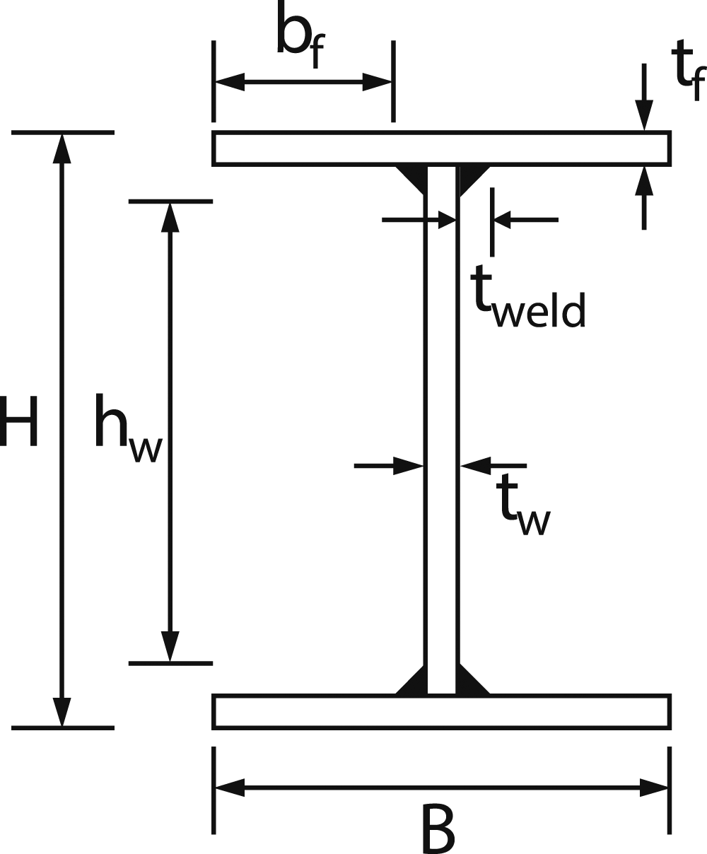
Basic modelling assumptions
The four-noded doubly curved shell element S4R with reduced integration and finite membrane strains has been extensively and successfully used in previous numerical investigations of NSS and HSS welded I-section structural elements (Yun et al., 2022; Zhu et al., 2023), and was also employed in the present study for the modelling of welded I-section stub columns. An element size approximately equal to (B + H)/40 was applied to the modelled stub columns in both the transverse and longitudinal directions; the adopted mesh size was shown to be able to capture the cross-section buckling response with reasonable computational efficiency. For validation purposes, the weld fillets of the I-sections were carefully modelled by means of five finer mesh elements with equal height but different widths, as shown in Figure 2. Nodes at both ends of the web were offset from the web-to-flange junctions by half the flange thickness tf/2 in order to avoid any overlap between the flange and web plates, as illustrated in Figure 2. The same mesh density as that employed in the present work has been successfully used for the modelling of welded I-section structural elements in previous studies (Yun et al., 2022; Zhu et al., 2023). Modelling approach for representing weld fillets in welded I-sections.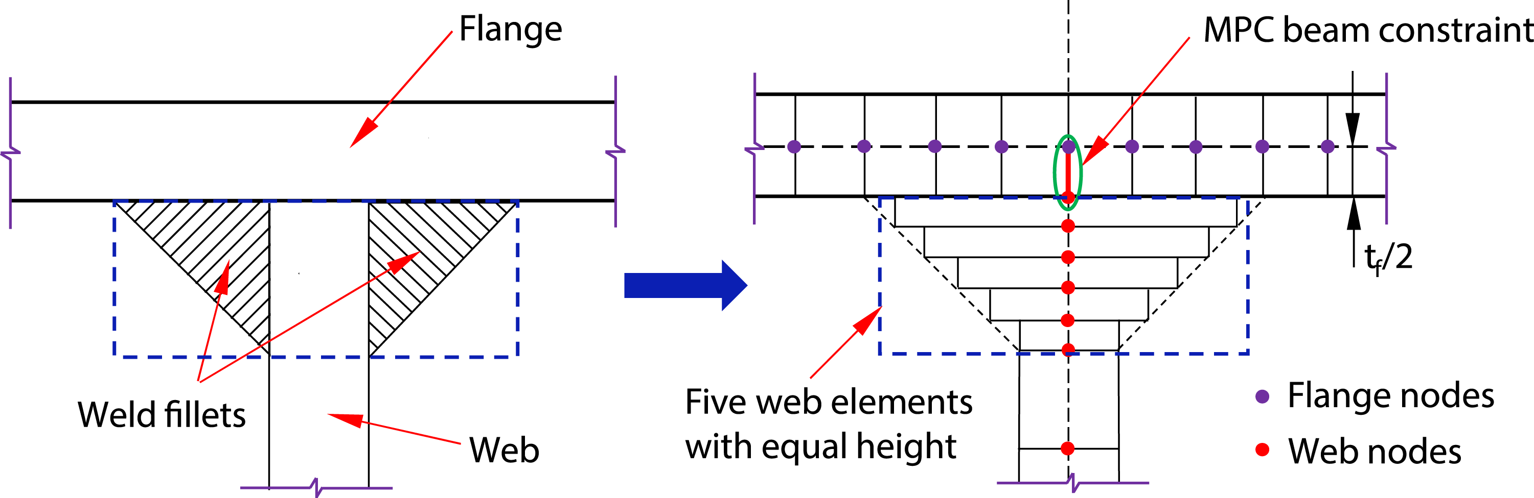
The modelled specimens were loaded through knife edges. A reference point representing the tip of the knife edge (i.e. the loading/reaction point) was created at each end section of the stub column FE models, as shown in Figure 3; the reference point was offset from the centroid of the end section laterally by a distance equal to the applied loading eccentricity (i.e. e0,y and e0,z for major axis bending and minor axis bending, respectively, as indicated in Figure 3) and longitudinally by the total thickness of the knife edge, wedge plate and end plate according to the test setup in (Su et al., 2021, 2021b; Sun et al., 2021) for model validation (i.e. e0,x as shown in Figure 3). The nodes at each end section of the stub column FE model were coupled to the corresponding reference point by means of kinematic coupling, with pinned in-plane and fixed out-of-plane boundary conditions assigned to the reference point. With regards to material properties for validation, the measured engineering stress-strain relationships obtained from tensile coupon tests reported in (Su et al., 2021, 2021b; Sun et al., 2021) were converted into true stress-logarithmic plastic strain curves before inputting into ABAQUS. Boundary conditions employed in finite element models of welded I-section stub columns subjected to compression plus uniaxial bending.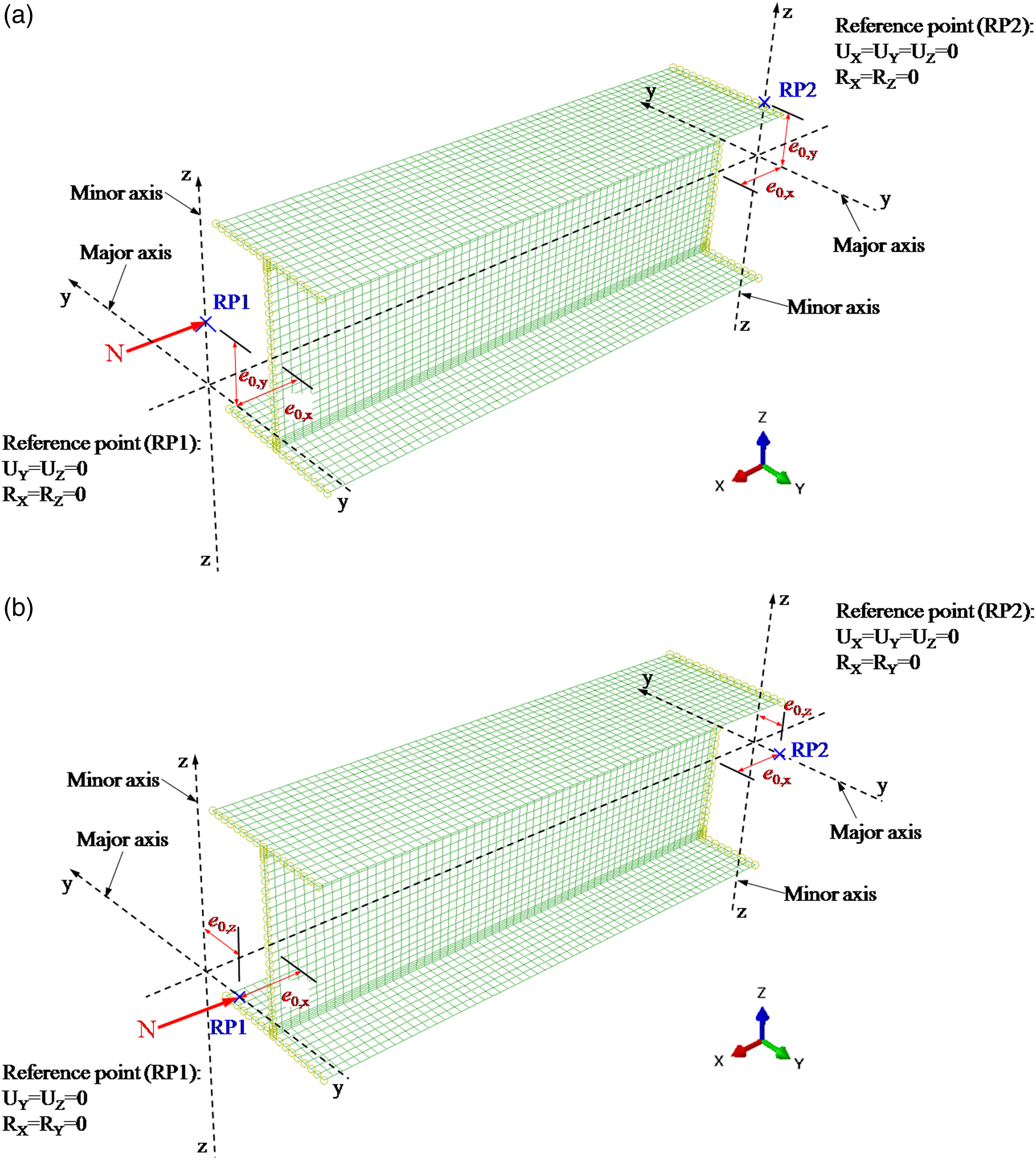
Initial local geometric imperfections were incorporated into the FE models in the form of sinusoidal half-waves of half-wavelength equal to L/3, where L is the length of the modelled stub column, in the longitudinal direction by means of adjusting the nodal coordinates of the original perfect geometry, as illustrated in Figure 4. The amplitudes of the local imperfections were taken as the measured values in the validation study and tolerance-based values set out in Annex C of EN1993-1-5 (2006) in the parametric studies. Specifically, the local imperfection amplitude of the flange Form and amplitudes of local geometric imperfections employed in finite element models.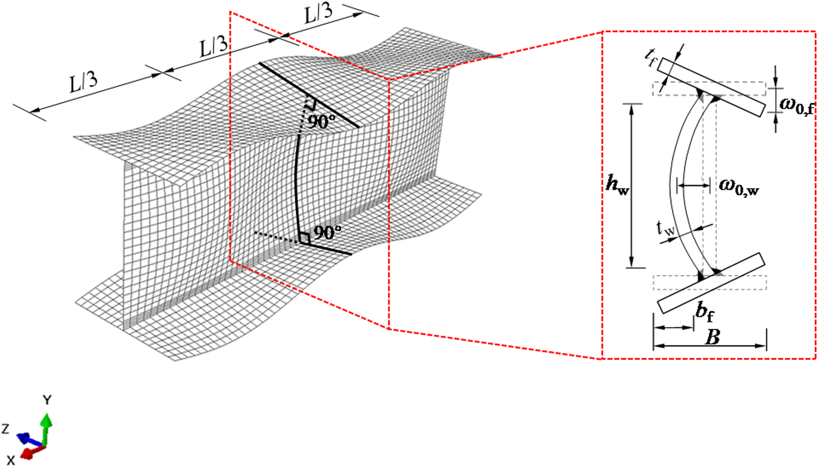
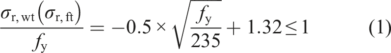
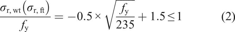
Residual stresses were incorporated into the FE models using the residual stress pattern put forward by Yun et al. (2023) for both NSS and HSS welded I-sections. The residual stress pattern (Yun et al., 2022a) was developed based on the statistical analysis of a large number of existing residual stress measurements collected from the literature, as shown in Figure 5, where σr,ft and σr,wt are the maximum tensile residual stresses in the flanges and the web, respectively, and σr,fc and σr,wc are the maximum compressive residual stresses in the flanges and the web, respectively. Note that compressive and tensile residual stresses are denoted as negative and positive values, respectively, as indicated in Figure 5. The maximum tensile residual stresses (i.e. σr,ft or σr,wt) can be predicted using equation (1) or equation (2), which correspond to the mean or upper characteristic (i.e. 95th percentile) values from the analysed residual stress data. As recommended in (Yun et al., 2022a), the residual stress pattern with the mean value of the maximum tensile residual stresses predicted by equation (1) can be used for validating FE models, while the residual stress pattern with the upper characteristic value of the maximum tensile residual stresses predicted by equation (2) should be used in parametric studies in order to generate safe-sided structural performance data. The residual stress model has been successfully employed in previous numerical studies of NSS and HSS welded I-section beams (Zhu et al., 2023) and columns (Yun et al., 2022a). A separate analysis step was created in order to achieve self-equilibrium of the residual stresses prior to the application of the external loading. The modified Riks method (Hibbitt et al., 1997), which is able to obtain nonlinear static equilibrium solutions for unstable problems, was adopted in order to capture the full load-deformation (including post-peak) response of the stub columns subjected to compression plus uniaxial bending. Residual stress pattern adopted in finite element models.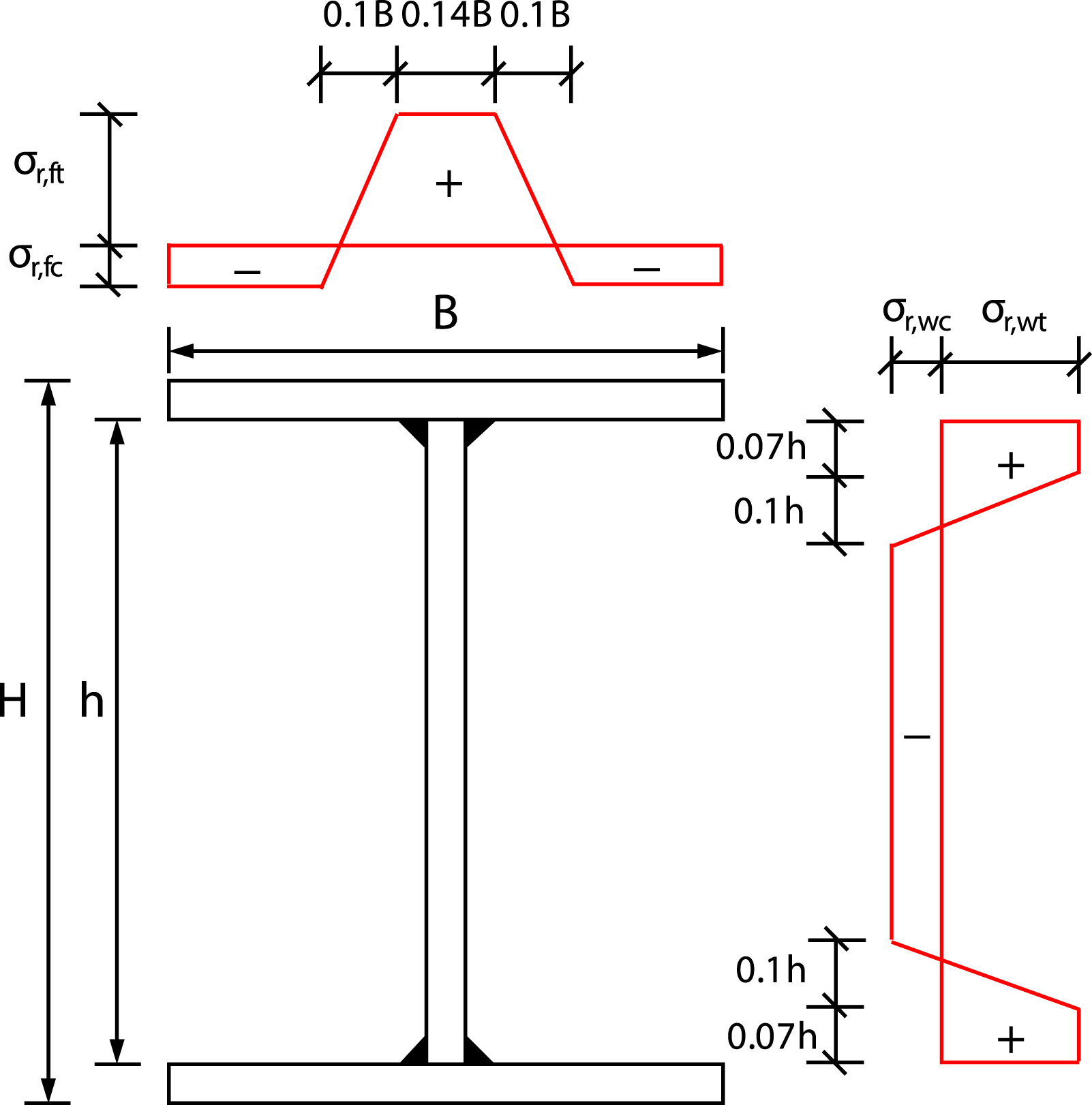
Validation of FE models
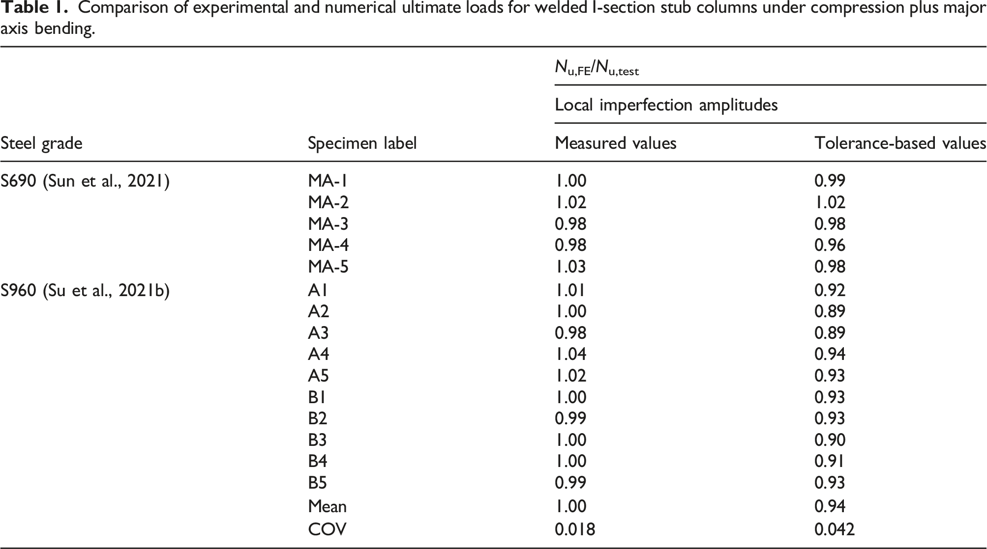
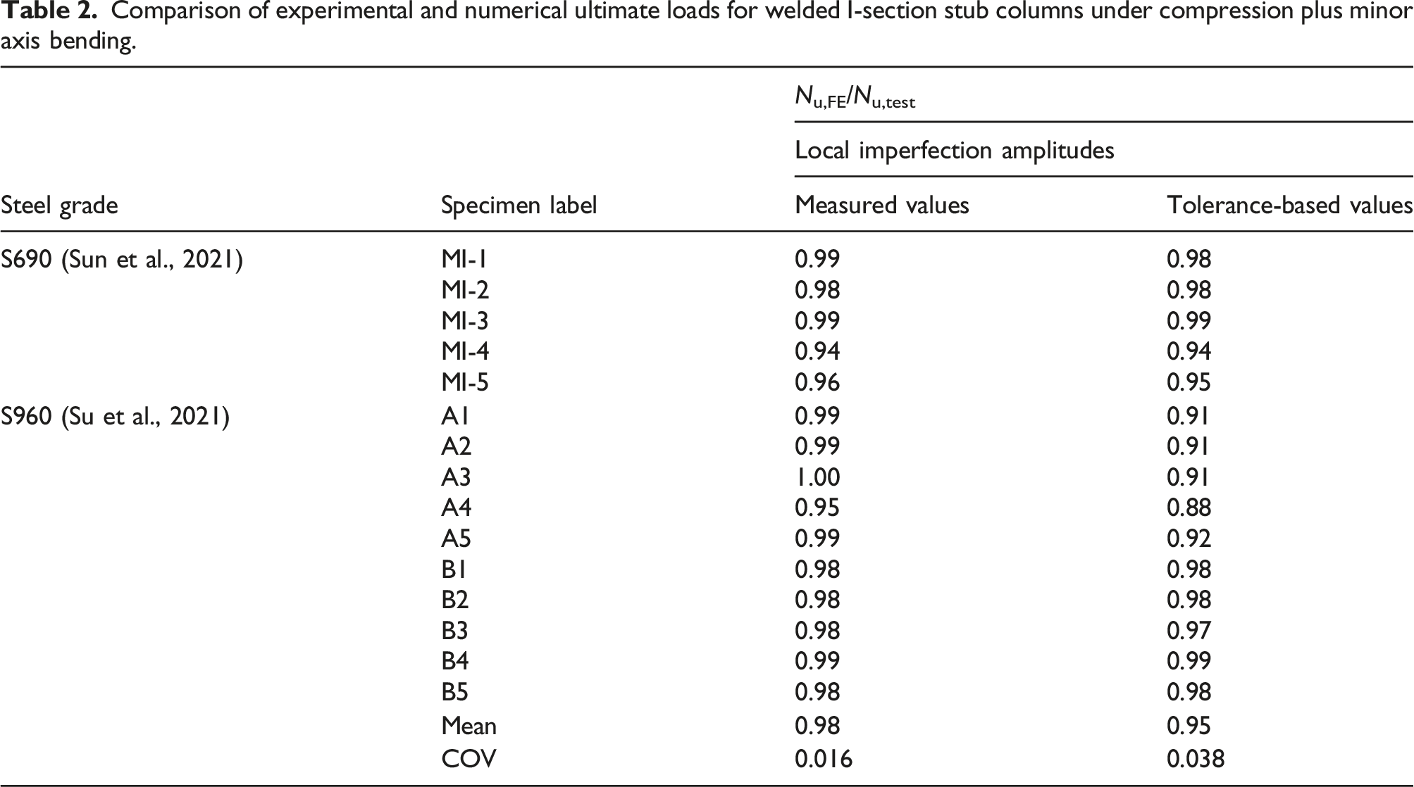
The accuracy of the developed FE models was verified through comparisons of the numerical results, in terms of the ultimate loads, load-lateral deformation histories and failure modes, with those obtained from physical tests (Su et al., 2021, 2021b; Sun et al., 2021). For test specimens whose weld leg lengths were not reported, the nominal values as recommended in Section J2 of AISC 360-16 (2016) were utilised in the FE models for validation purposes. Both measured and tolerance-based local imperfection amplitudes were incorporated into the FE models with the aims of assessing the sensitivity of the developed FE models to variation in local imperfection amplitudes and examining the suitability of the tolerance-based local imperfection amplitudes for use in the parametric studies.
Comparison of experimental and numerical ultimate loads for welded I-section stub columns under compression plus major axis bending.
Comparison of experimental and numerical ultimate loads for welded I-section stub columns under compression plus minor axis bending.
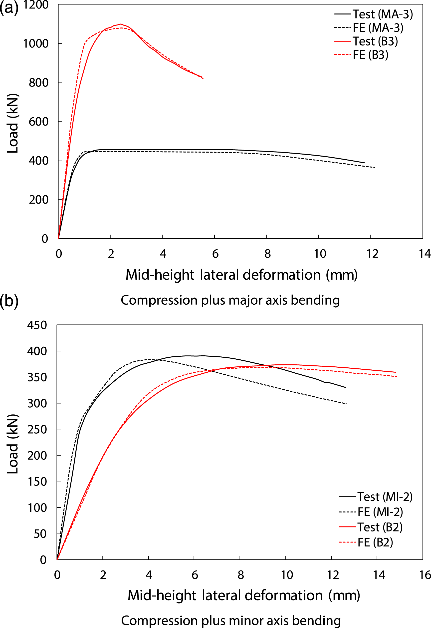
Comparison of experimental (Su et al., 2021, 2021b; Sun et al., 2021) and numerical load-mid-height deformation histories for stub column specimens subjected to compression plus uniaxial bending.
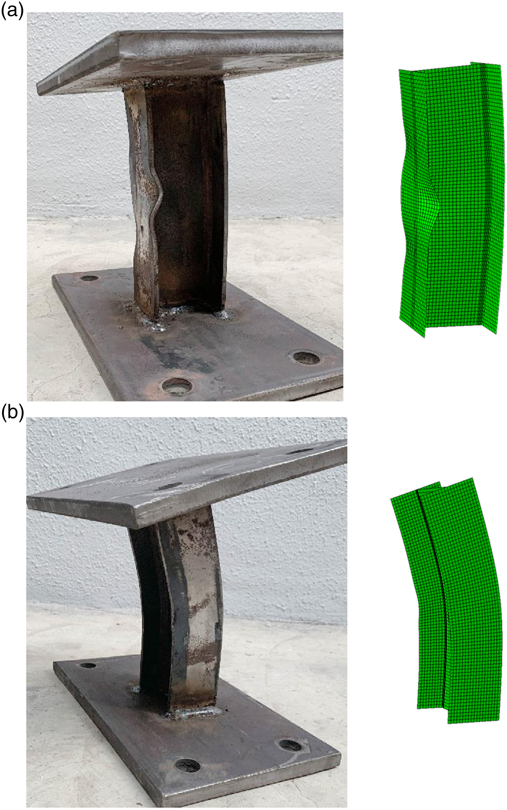
Comparison of experimental and numerical failure modes for stub columns subjected to compression plus uniaxial bending.
Parametric studies
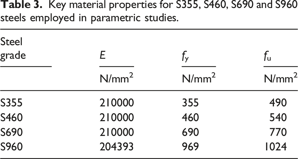
Key material properties for S355, S460, S690 and S960 steels employed in parametric studies.
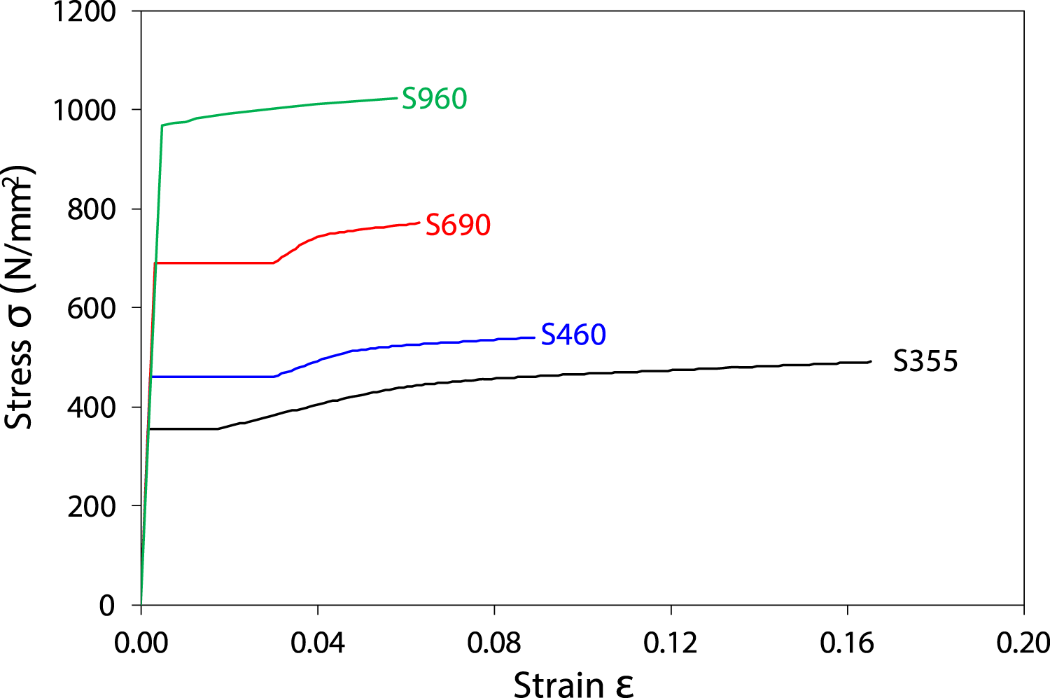
Full-range stress-strain curves for S355, S460, S690 and S960 steels employed in parametric studies.
Regarding the cross-section dimensions of the modelled welded I-sections, the flange width B was fixed at 100 mm, while the outer section depths H were taken as 100 mm, 150 mm and 200 mm, resulting in three different cross-section aspect ratios H/B of 1.0, 1.5 and 2.0. For each cross-section aspect ratio, three different values of flange thickness tf, varying from 5.6 mm to 14 mm, and web thickness tw, varying from 3.4 mm to 20 mm, were selected to achieve a spectrum of local slenderness covering all three non-slender cross-section classes (i.e. Class 1–3) on the basis of the slenderness limits set out in EN 1993-1-1 (2005, 2019) and EN 1993-1-12 (2007). For each modelled welded I-section, the flange and web thicknesses were specified such that the web plate slenderness
The initial loading eccentricities for each modelled welded I-section in both the major and minor axis directions were varied between 0.8 mm and 691 mm so that a broad variety of loading combinations could be obtained. In total, 1320 numerical results on NSS and HSS welded I-sections under compression plus uniaxial bending were generated through the parametric studies, comprising 648 data for compression plus major axis bending and 672 for compression plus minor axis bending.
Stability design of welded I-sections under compression plus uniaxial bending
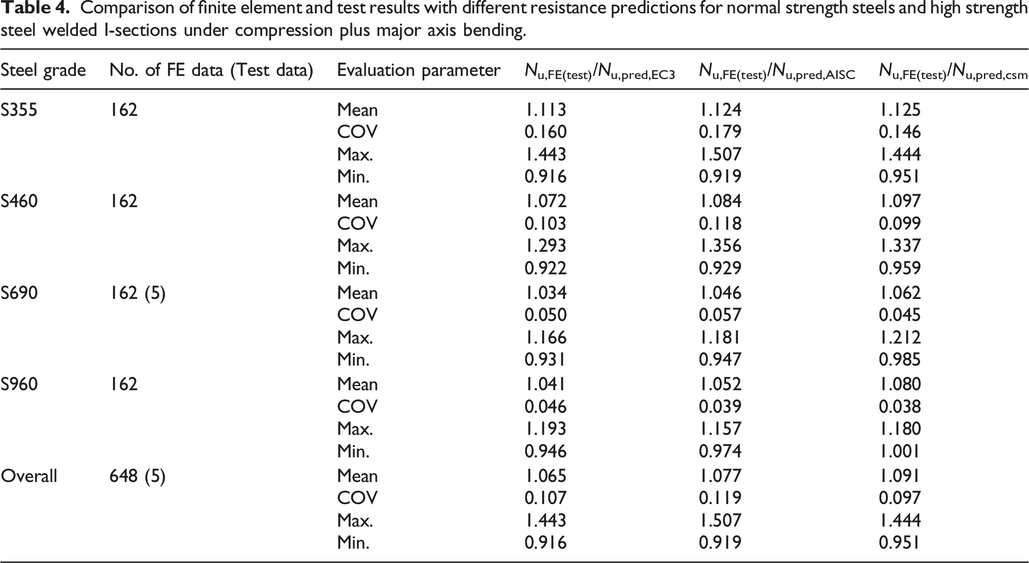
Comparison of finite element and test results with different resistance predictions for normal strength steels and high strength steel welded I-sections under compression plus major axis bending.
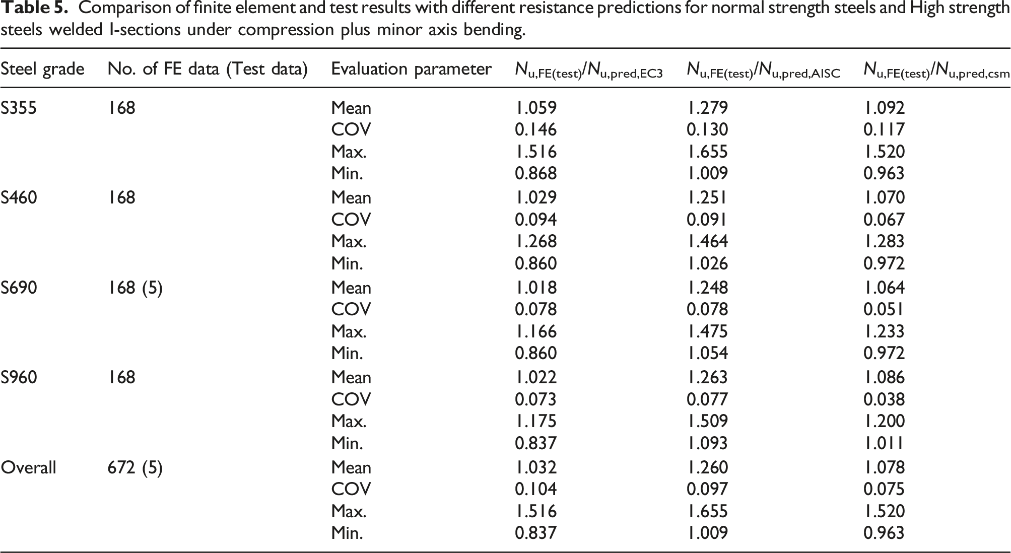
Comparison of finite element and test results with different resistance predictions for normal strength steels and High strength steels welded I-sections under compression plus minor axis bending.
European codes EN 1993-1-1 and EN 1993-1-12 (EC3)
The current EC3 design provisions for HSS structures are given in EN 1993-1-12 (2007). The rules largely follow those set out in EN 1993-1-1 (2005, 2019) for NSS structures; no distinction is made between NSS and HSS in the local stability and cross-section checks. In addition, EN 1993-1-12 (2007) is applicable to steel grades up to S700, thus no design rules are offered for steel members made of ultra-HSS (e.g. S960). In this subsection, the accuracy and applicability of the current EC3 design provisions for both NSS and HSS (up to S960) welded I-sections subjected to combined compression and bending are assessed.
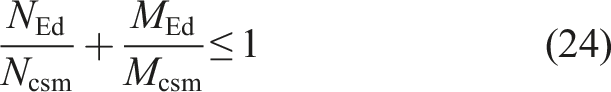
EN 1993-1-1 (2005) adopts a linear interaction formula for the design of Class 3 (i.e. semi-compact) welded I-sections under compression plus major axis bending and a nonlinear interaction formula for compression plus minor axis bending. In the latest draft of the new version of this code, prEN 1993-1-1 (2019), the same interaction formulae are used, but with the concept of an elasto-plastic moment introduced — see equations (3) and (4).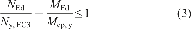
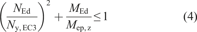
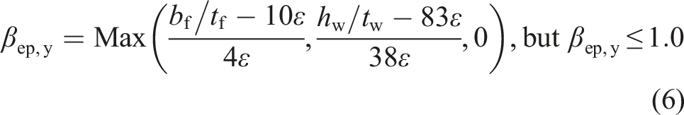
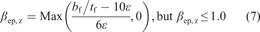
The elasto-plastic section modulus Wep is determined from an interpolation between the plastic section modulus Wpl and the elastic section modulus Wel about the considered axis of bending, as given by equation (5)
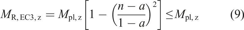
A bilinear interaction formula, as given by equation (8), is employed for the design of Class 1 and 2 welded I-sections under compression plus major axis bending, while a nonlinear interaction formula, as given by equation (9), is utilised for those subjected to compression plus minor axis bending.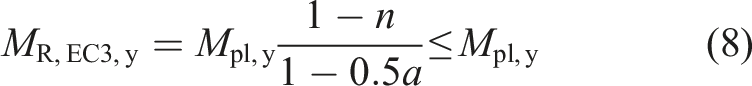
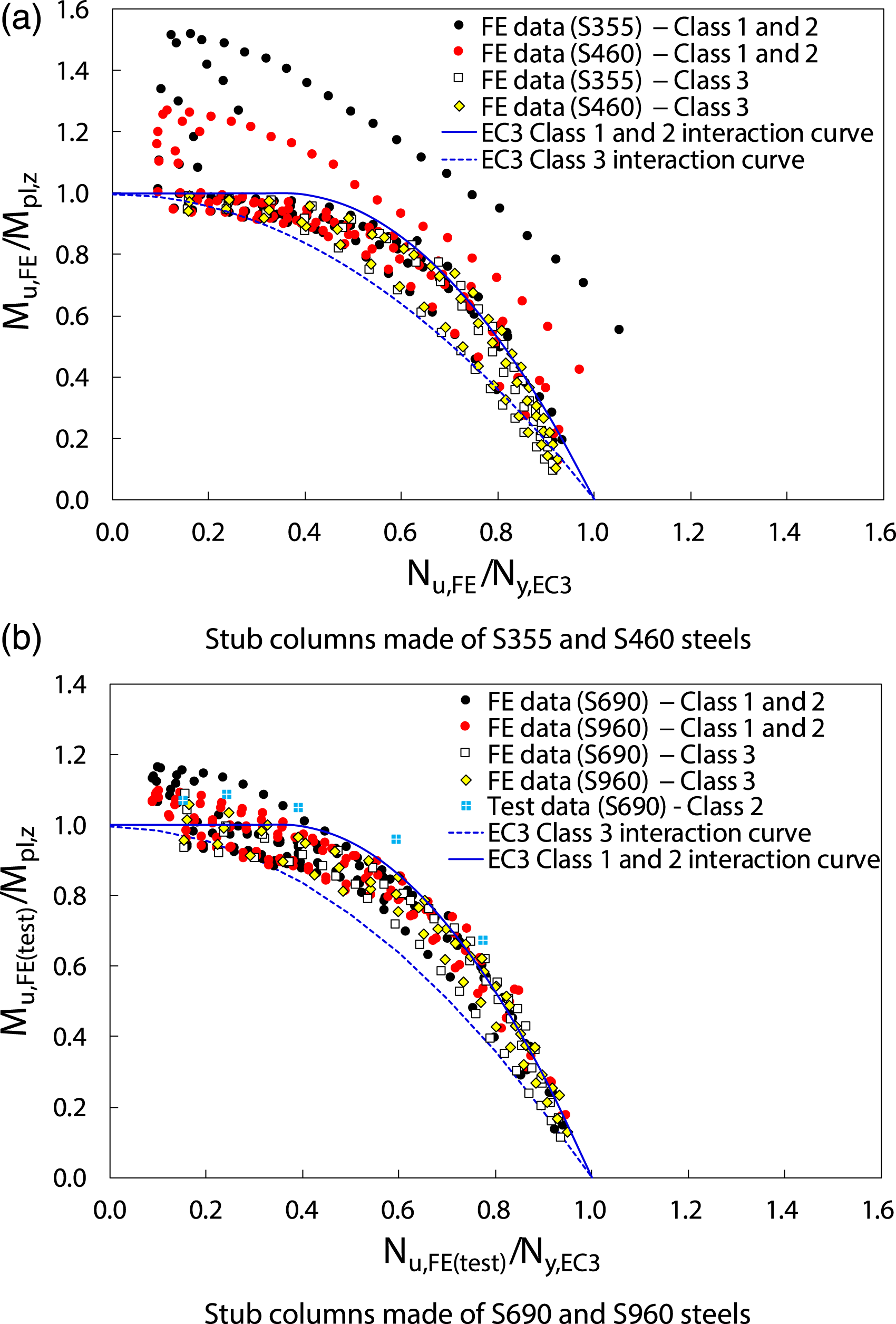
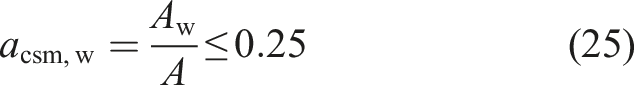
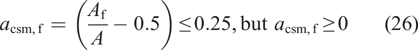
The accuracy of the EC3 interaction formulae (Equations (8) and (9)) for NSS and HSS welded I-sections under combined compression plus uniaxial bending was assessed based on the FE and test data. A graphical assessment was carried out, as shown in Figures 9 and 10 for welded I-sections subjected to compression plus major axis and minor axis bending, respectively, where the FE and test ultimate bending moments Mu,FE(test) (calculated considering second order effects) and axial loads Nu,FE(test) are normalised by their respective plastic bending resistances Mpl and yield loads Npl, and are compared with the EC3 interaction curves. Note that the EC3 interaction curves depend on geometry-related parameters, such as the ratio of the web-to-gross cross-section area a for Class 1 and 2 welded I-sections and the ratio of the elasto-plastic-to-plastic section modulus Wep/Wpl for Class 3 welded I-sections; thus, the average interaction curves determined based on the average geometric properties of the investigated welded I-sections are plotted in Figures 9 and 10 for illustration purposes. As shown in Figures 9 and 10, for Class 1 and 2 welded I-sections, the EC3 interaction curves generally yield conservative resistance predictions particularly for stockier welded I-sections made of lower steel grades (i.e. S355 and S460 steels which exhibit a higher degree of strain hardening than the S690 and S960 steels). The overall conservatism under combined loading is attributed principally to the conservatism in the predictions of the cross-sectional compression and bending resistances (serving as the end points of the interaction curves) arising from the beneficial influence of strain hardening being neglected. However, there are also a large number of data points lying on the unsafe side for Class 1 and 2 welded I-sections with less stocky cross-sections, especially for those subjected to compression plus minor axis bending, as shown in Figure 10; this stems largely from the shape of the interaction curves, which feature a fixed plateau length of 0.5a for welded I-sections subjected to compression plus major axis bending and a for welded I-sections subjected to compression plus minor axis bending. For Class 3 welded I-sections, both the linear (for compression plus major axis bending) and the nonlinear (for compression plus minor axis bending) interaction curves yield accurate resistance predictions, as shown in Figures 9 and 10, resulting from the use of accurate bending end points (i.e. elasto-plastic bending resistance Mep) and suitable forms of interaction curves. It can also be seen from Figures 9 and 10 that for less stocky welded I-sections (i.e. Class 2 welded I-sections whose slendernesses approach the Class 3 limits and Class 3 welded I-sections), the influence of the steel grade on the cross-sectional buckling resistances is seen to be negligible since there is no or little strain hardening experienced. Comparison of normalised finite element and test results with average EC3 interaction curves for normal strength steels and high strength steels welded I-sections under compression plus major axis bending. Comparison of normalised finite element and test results with average EC3 interaction curves for normal strength steels and high strength steels welded I-sections under compression plus minor axis bending.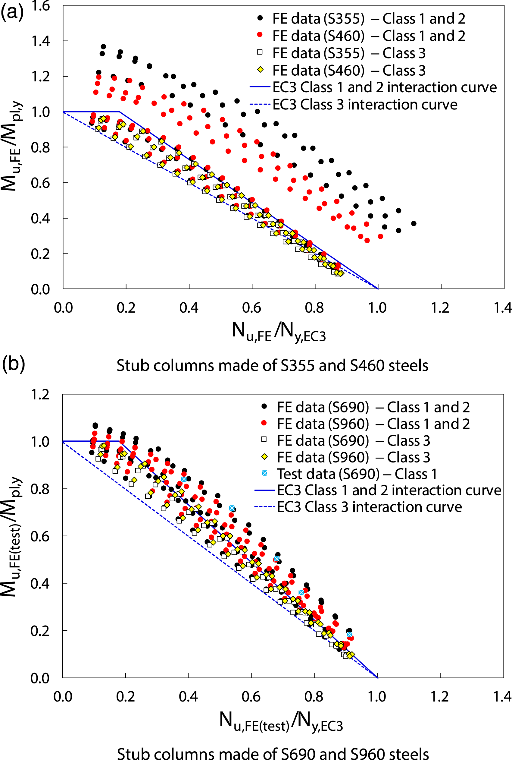
In addition, the ratios of the FE and test ultimate loads Nu,FE(test) to the ultimate capacities predicted by EC3 Nu,pred,EC3 are plotted against the cross-section slenderness Comparison of finite element and test results with EC3 resistance predictions for normal strength steels and high strength steels welded I-section stub columns subjected to compression plus uniaxial bending.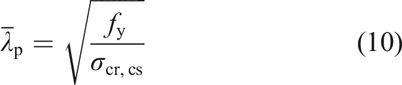
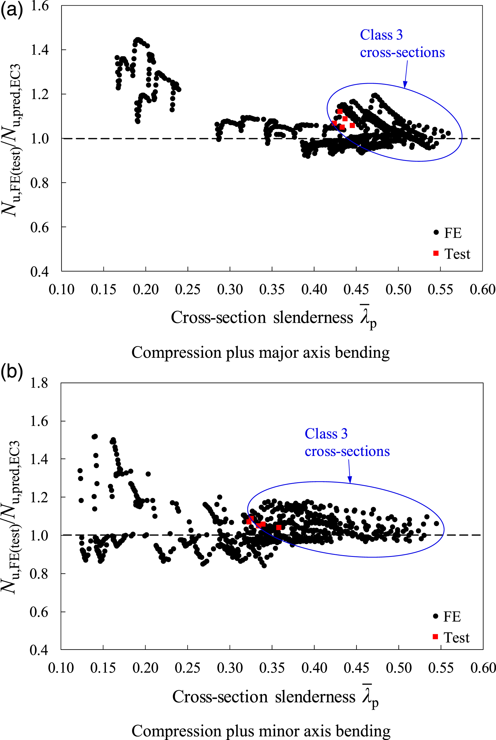
The full cross-section local buckling stress σcr,cs can be determined either using the empirical formulae of Gardner et al. (2019), as adopted in the present study, or using numerical tools such as CUFSM (Schafer and Adany, 2006). It can be observed from Figures 9–11 that the EC3 design approach provides somewhat inaccurate and scattered resistance predictions for welded I-sections subjected to compression plus uniaxial bending, which is evidenced by the statistical results summarised in Tables 4 and 5. For very stocky welded I-sections, whose cross-sectional responses are dominated by yielding, stub columns made of NSS are able to achieve higher normalised ultimate capacities than their HSS counterparts, primarily due to the higher level of strain hardening of NSS. However, the differences in the normalised ultimate capacities between stub columns made of NSS and HSS become small for less stocky welded I-sections with
American specification AISC 360-16 (AISC)
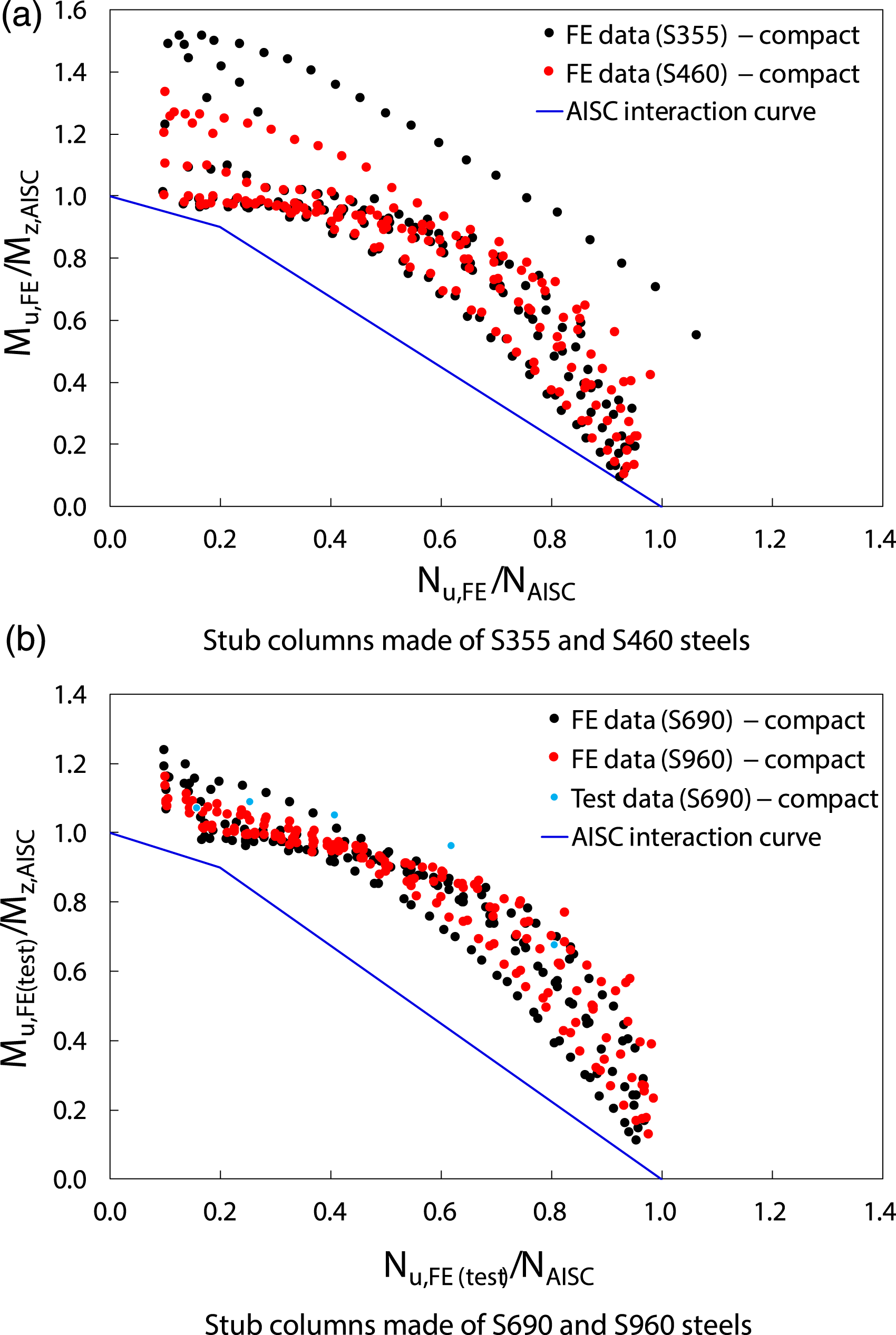
The American specification AISC 360-16 (2016) employs a bilinear interaction curve, as expressed by equation (11), for the design of non-slender welded I-sections under combined loading, where NAISC is the nominal cross-sectional compression resistance and MAISC is the nominal cross-sectional bending resistances about the considered axis of bending. The nominal compression resistance of a non-slender welded I-section (i.e. equivalent to a Class 1–3 welded I-section according to EC3) NAISC is calculated through multiplying the gross cross-sectional area A by the flexural buckling stress fcr. Compared to the EC3 cross-sectional yield load Ny,EC3, the yield strength fy is replaced by the flexural buckling stress fcr to determine the AISC cross-sectional compression resistance NAISC, which accounts for the influence of the second order effects, though these are minimal for short members, as studied herein. The flexural buckling stress fcr were calculated in accordance with Section E3 of AISC 360-16 (2016). The nominal cross-sectional bending resistances MAISC were determined according to Sections F3 and F6 of AISC 360-16 (2016), which employ the plastic bending resistances Mpl for compact welded I-sections (i.e. equivalent to Class 1 and 2 welded I-sections in EC3) and elasto-plastic bending resistances allowing for the partial spread of plasticity for semi-compact welded I-sections (i.e. equivalent to Class 3 welded I-sections in EC3).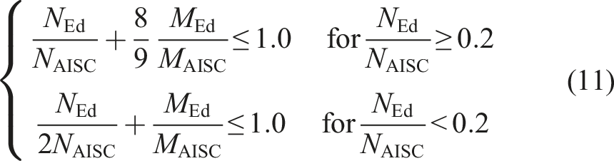
The accuracy of the AISC interaction formula (equation (11)) for NSS and HSS welded I-sections subjected to compression plus uniaxial bending was assessed based on the FE and test results. The FE and test ultimate bending moments Mu,FE(test) (considering second order effects) and axial loads Nu,FE(test) are normalised by their respective AISC cross-sectional bending resistances MAISC and compression resistances NAISC, and are compared with the AISC interaction curve (equation (11)), as shown in Figures 12 and 13 for welded I-sections subjected to compression plus major axis and minor axis bending, respectively. It should be noted that, due to the different cross-section classification frameworks employed in EC3 and AISC, all the welded I-sections investigated in the present study are classified as compact cross-sections according to AISC. For the EC3 Class 1 and 2 welded I-sections, the AISC bilinear interaction curves provide more conservative resistance predictions than EC3, whose interaction curves feature a plateau in the region with lower axial load ratios. For the EC3 Class 3 welded I-sections, AISC yields less conservative strength predictions for the case of compression plus major axis bending, though there are a number of data points appearing on the unsafe side, as shown in Figure 12, but provides rather conservative resistance predictions for the case of compression plus minor axis bending, as shown in Figure 13, compared to EC3. Comparison of normalised finite element and test results with the North American interaction curves for normal strength steels and high strength steels welded I-sections under compression plus major axis bending. Comparison of normalised finite element and test results with the North American interaction curves for normal strength steels and high strength steels welded I-sections under compression plus minor axis bending.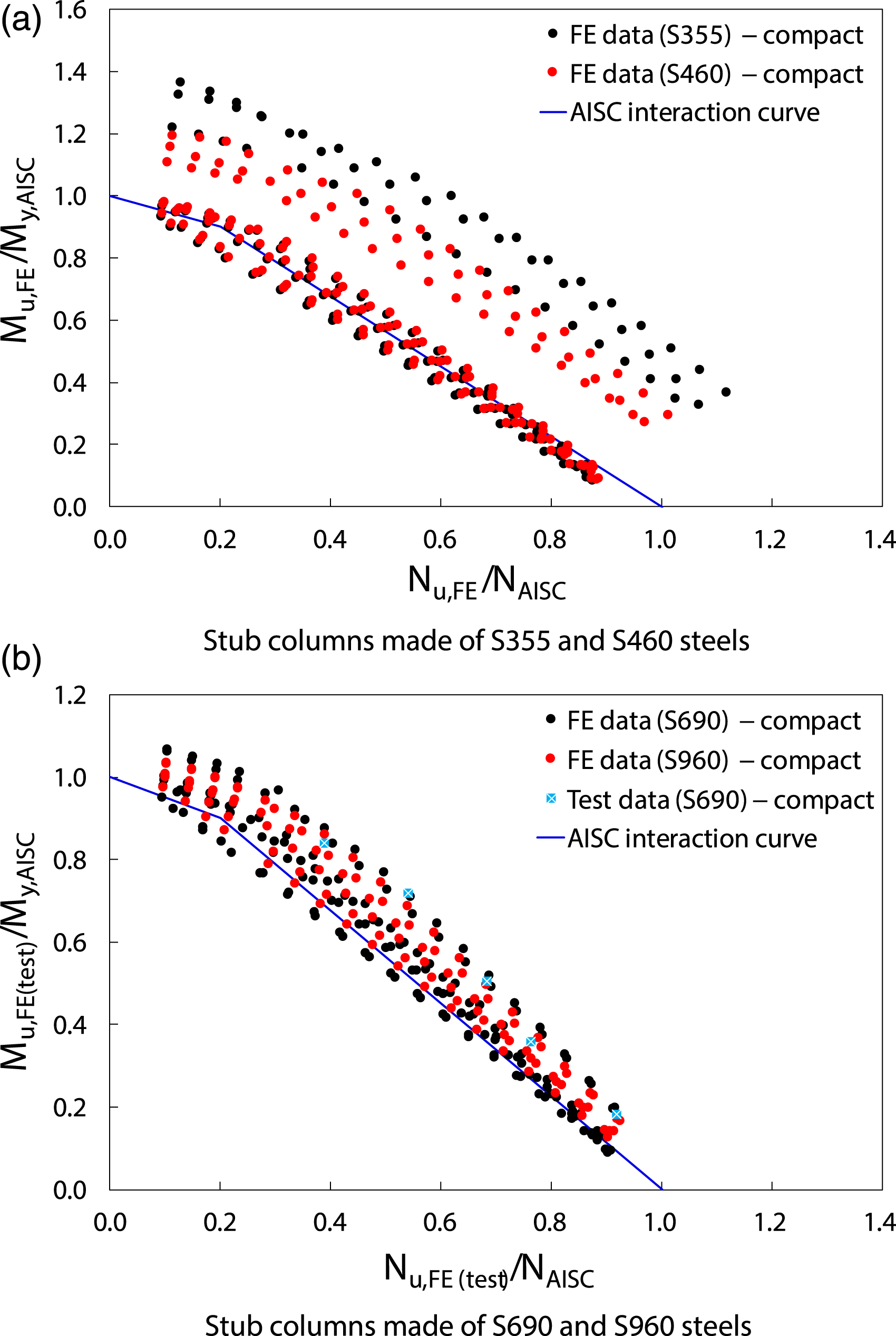
The ratios of the FE and test ultimate loads Nu,FE(test) to the ultimate resistances predicted by AISC Nu,pred,AISC are plotted against the cross-section slenderness Comparison of finite element and test results with North American resistance predictions for normal strength steels and high strength steels welded I-section stub columns subjected to compression plus uniaxial bending.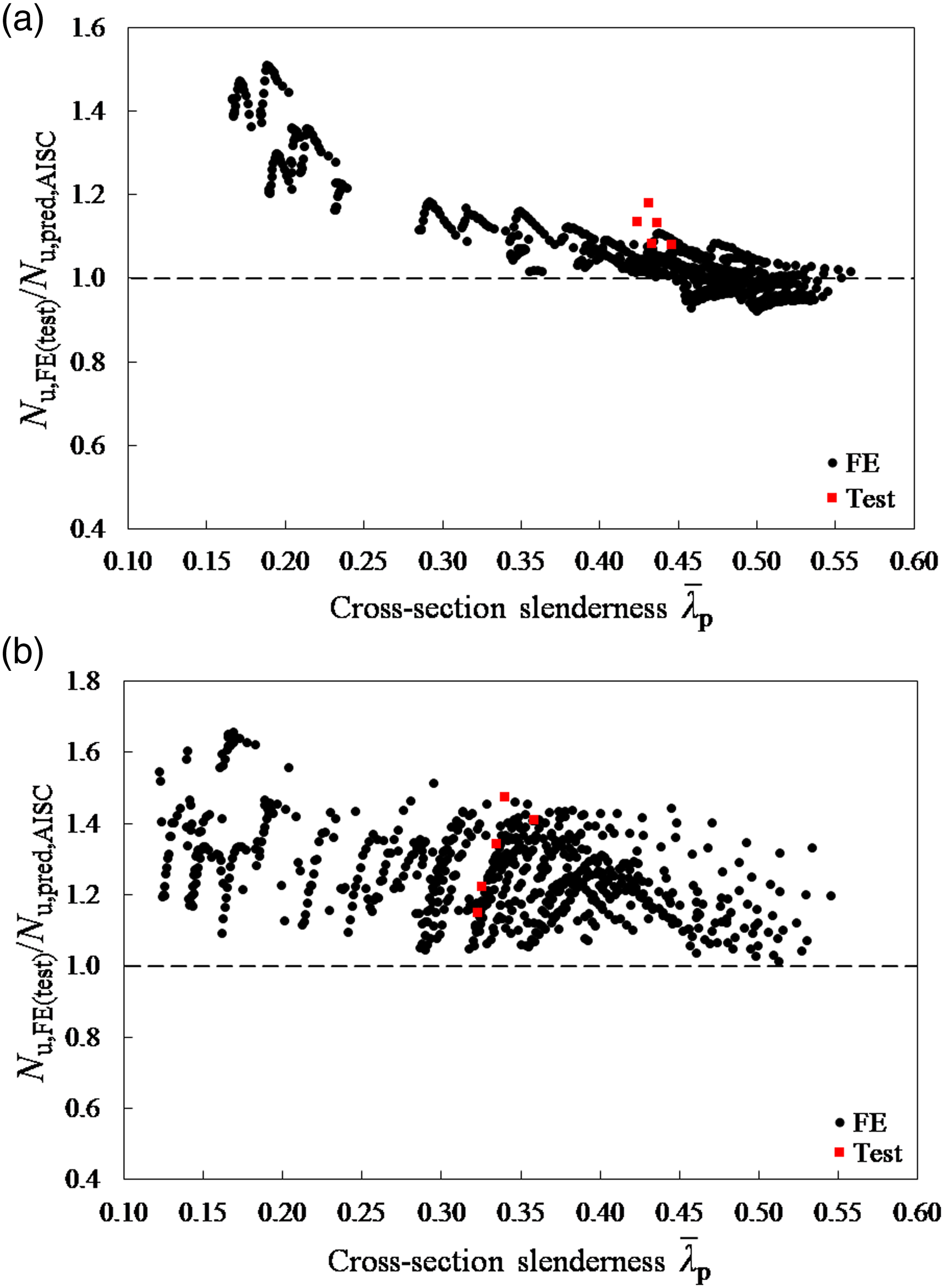
New CSM-based design proposals
On the basis of the previous evaluations, it is generally revealed that the existing design methods provide somewhat inaccurate and scattered resistance predictions for NSS and HSS welded I-sections subjected to compression plus uniaxial bending. Yun et al. (2018b) proposed an improved design approach, based on the CSM (Yun et al., 2018a) for the calculation of cross-sectional compression and bending resistances and the general format of the EC3 interaction formula, for NSS hot-rolled steel I-sections under combined loading (Yun et al., 2018b). In this subsection, a new design method, based on (Yun et al., 2018b), is proposed for NSS and HSS welded I-sections subjected to compression plus uniaxial bending.
The design method proposed for NSS hot-rolled steel I-sections under combined loading (Yun et al., 2018b) utilises the CSM compression and bending resistances as the end points, which have been shown to be more accurate than the EC3 and AISC predictions (Yun et al., 2018a). The CSM is a deformation-based method that enables a rational allowance of material nonlinearity (i.e. the spread of plasticity and strain hardening) in determining the cross-sectional resistances of steel structural elements. The CSM consists of two fundamental components − a ‘base curve’ that defines the limiting strain εcsm that a cross-section can resist prior to failure and a constitutive model that allows for the influence of strain hardening. The limiting strain εcsm for a given non-slender welded I-section (i.e. 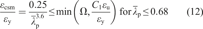
A quad-linear material model, proposed by Yun and Gardner (2017), has been employed throughout the recent development of the CSM for the design of NSS and HSS structural elements. The quad-linear material model is shown in Figure 15 and defined by equation (13), where ɛ and σ are the engineering strain and stress, respectively, εsh is the strain hardening strain at which the material yield plateau ends and strain hardening initiates and Esh is the strain hardening modulus defined as the slope of the third linear stage of the model that passes through the strain hardening point (εsh, fy) and a specified maximum point (C2εu, fu), as shown in Figure 15. Typical test stress-strain curve and the quad-linear model for normal strength steels and high strength steels (Yun and Gardner, 2017).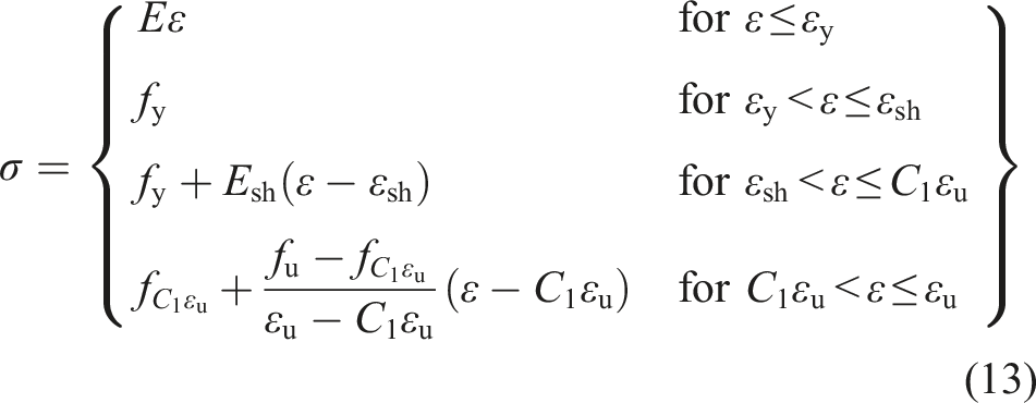
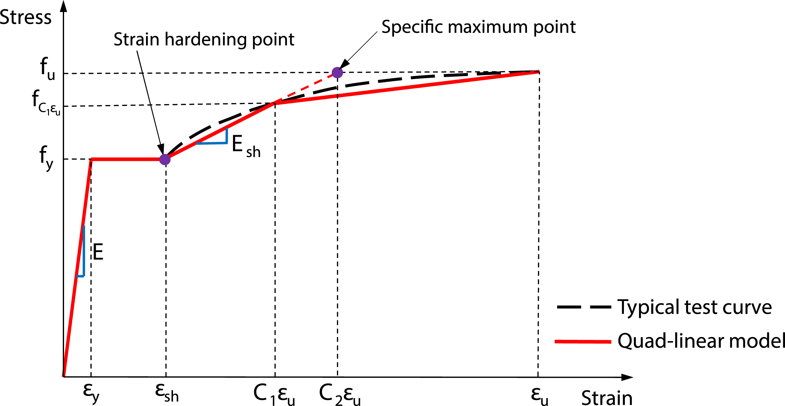
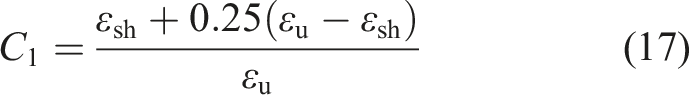
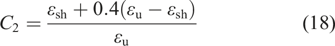
Two coefficients are adopted in the quad-linear material model: the first coefficient C1 defines the transition strain (i.e. C1εu) to the fourth stage of the quad-linear model, and the second coefficient C2 is used to define the strain hardening modulus Esh, as given by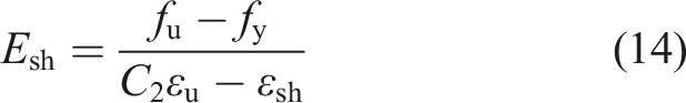
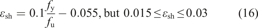
The parameters εu, εsh, C1 and C2 used in the quad-linear material model can be determined from the predictive expressions of equations (15)–(18), respectively.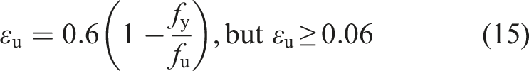

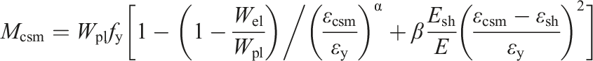
For non-slender (i.e. Class 1–3) NSS and HSS welded I-sections, the CSM bending resistance Mcsm is determined by equation (20) when strain hardening is not experienced (i.e. εcsm < εsh) and equation (21) for stockier cross-sections whose CSM limiting strain εcsm exceeds the strain hardening strain εsh and strain hardening is experienced. In equations (20) and (21), α and β are dimensionless coefficients that are equal to 1.2 and 0.05 for I-sections bending about their minor axis, respectively, and equal to 2 and 0.08 for I-sections bending about their major axis, respectively.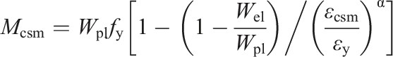


Yun et al. (2018b) proposed an improved design approach for NSS non-slender hot-rolled I-sections subjected to combined compression and bending moment. The proposed design approach features the use of the N-M interaction expressions specified in EC3 but with CSM cross-sectional compression and bending resistances as the end points, as given by equations (22) and (23) for hot-rolled I-sections with 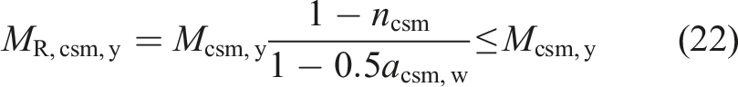
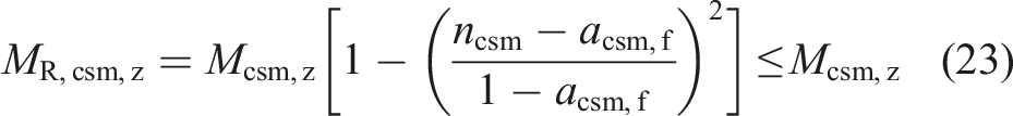
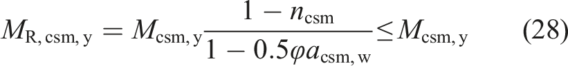
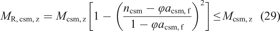
The applicability of a similar design approach (Yun et al., 2018b) to NSS and HSS non-slender (i.e. Class 1–3) welded I-sections under combined loading is explored in this subsection. A slight modification was made to equations (22) and (23) by introducing a reduction factor φ for the plateau length of the interaction curves (Fieber et al., 2019, 2020; Yun and Gardner, 2018; Yun et al., 2020), as given by equation (27), enabling a gradual decrease in plateau length with increasing cross-sectional slenderness 
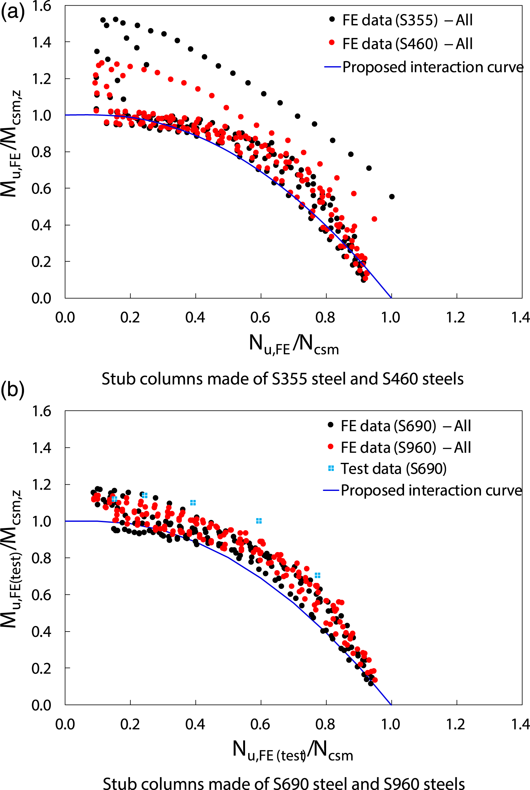
The numerically and experimentally obtained ultimate bending moments Mu,FE(test) (considering second order effects) and axial compression loads Nu,FE(test) are normalised by their respective CSM cross-sectional bending resistances Mcsm and compression resistances Ncsm, and are compared with the average proposed interaction curves (Equations (28) and (29)), as shown in Figures 16 and 17 for welded I-sections subjected to compression plus major axis and minor axis bending, respectively. It can be observed from Figures 16 and 17 that the FE and test data points follow a tighter trend for both loading cases compared to the EC3 and AISC predictions, with the majority of the data set lying above the proposed interaction curves (i.e. on the safe side). Comparison of normalised finite element and test results with average proposed interaction curves for normal strength steels and high strength steels welded I-sections under compression plus major axis bending. Comparison of normalised finite element and test results with average proposed interaction curves for normal strength steels and high strength steels welded I-sections under compression plus minor axis bending.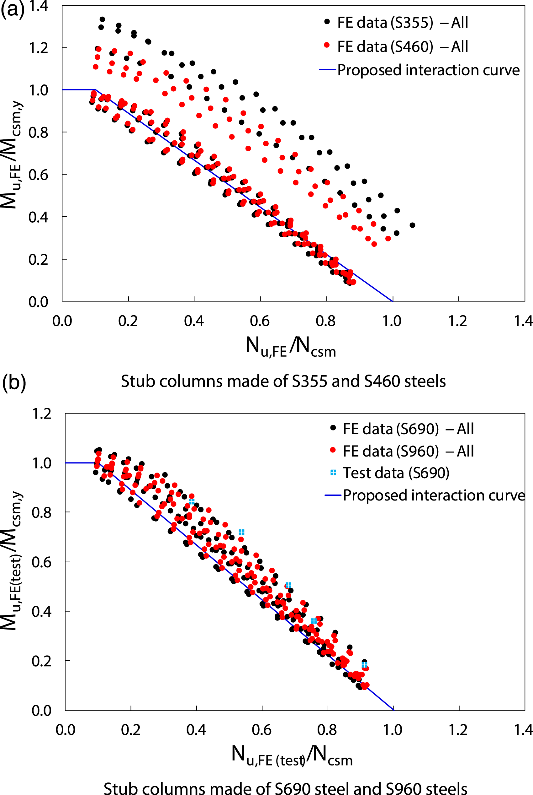
The improved accuracy and consistency of the proposed design approach can also be seen in Figure 18(a) and (b), where the ratios of FE and test ultimate loads Nu,FE(test) to ultimate resistances predicted by the proposed method Nu,pred,csm are plotted against the cross-section slenderness Comparison of finite element and test results with resistances predicted by the proposed method for normal strength steels and high strength steels welded I-section stub columns subjected to compression plus uniaxial bending.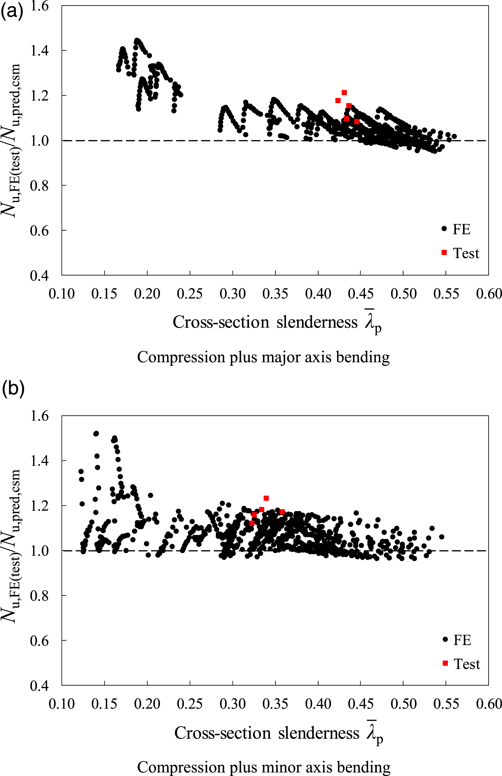
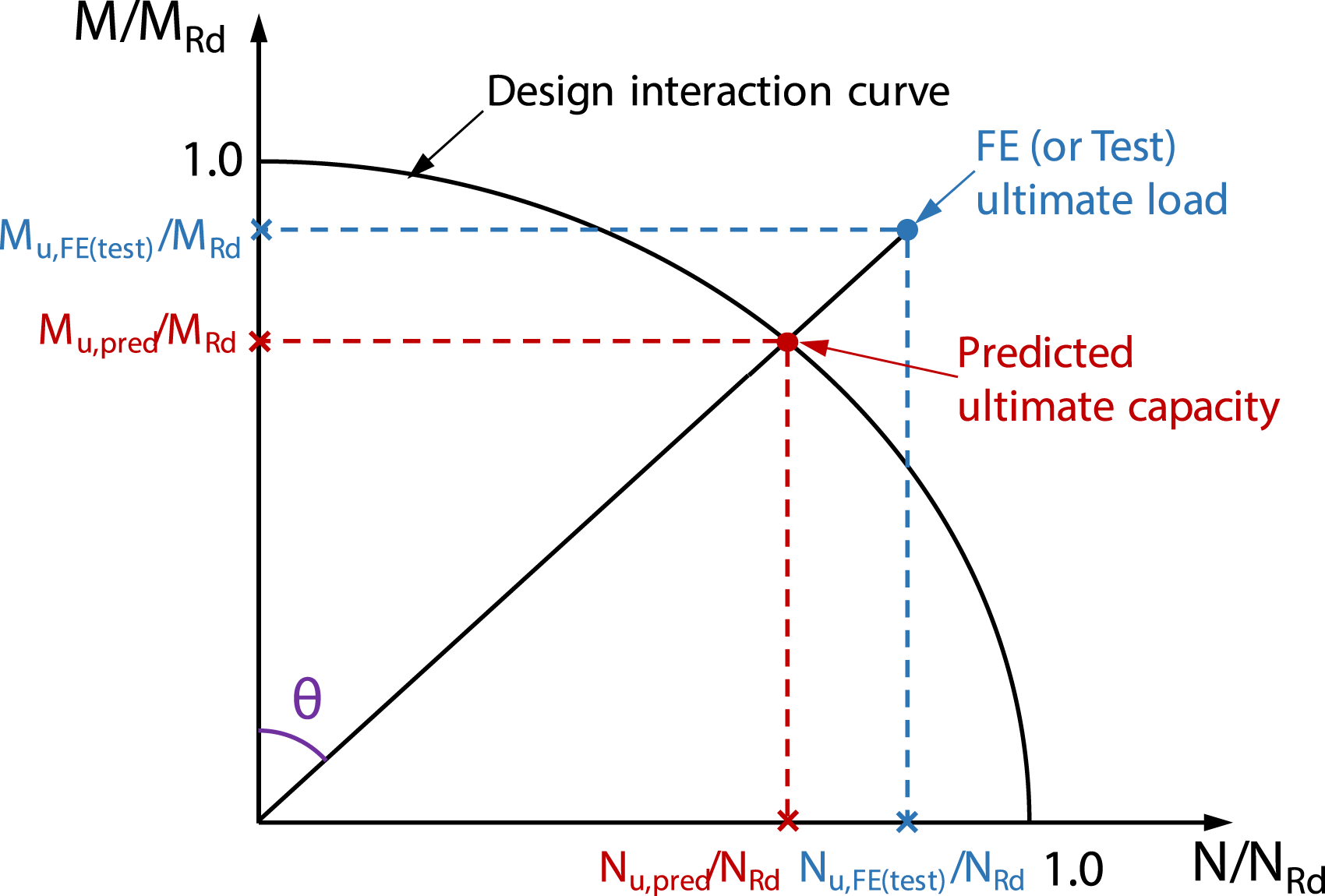
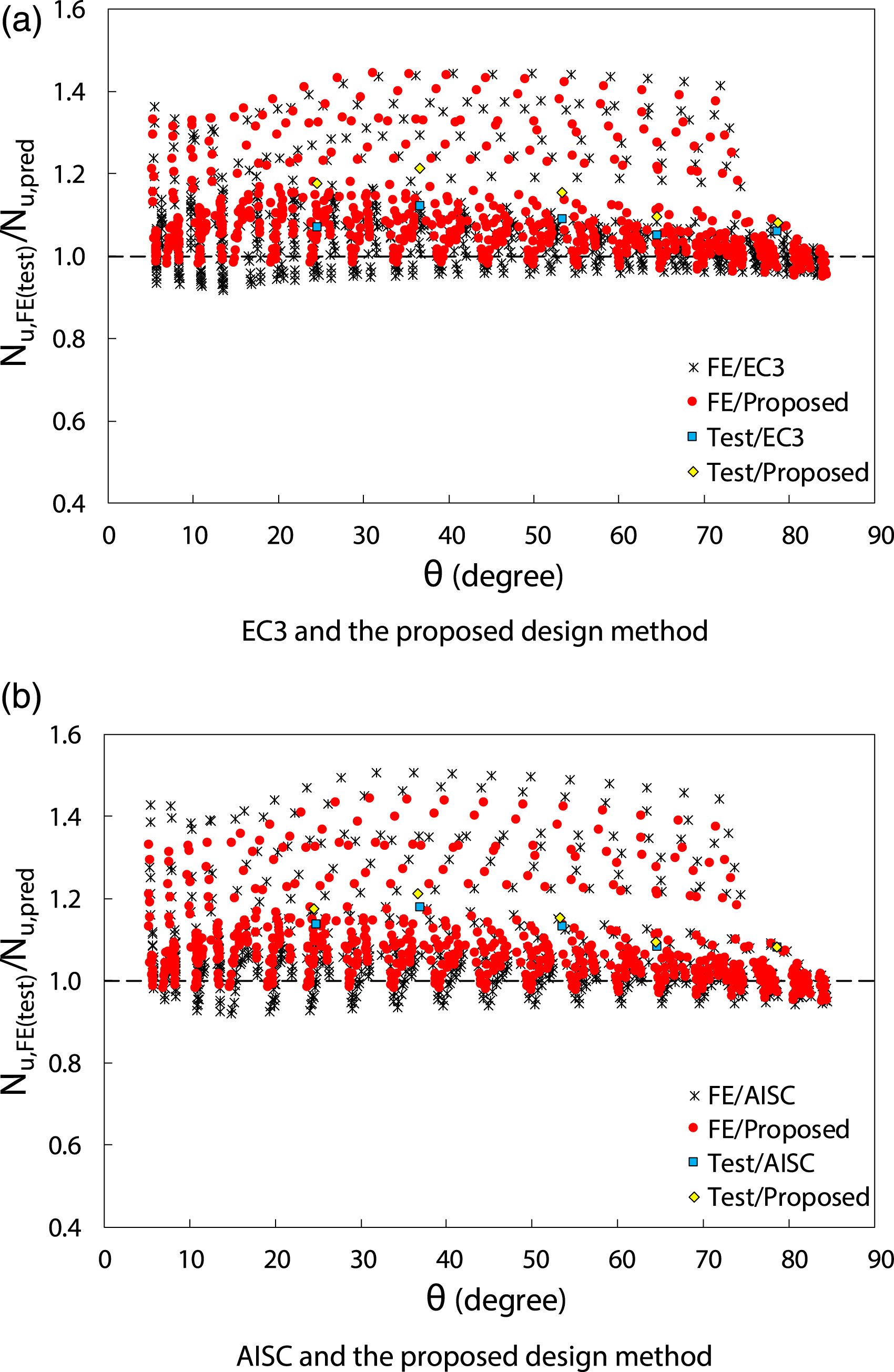
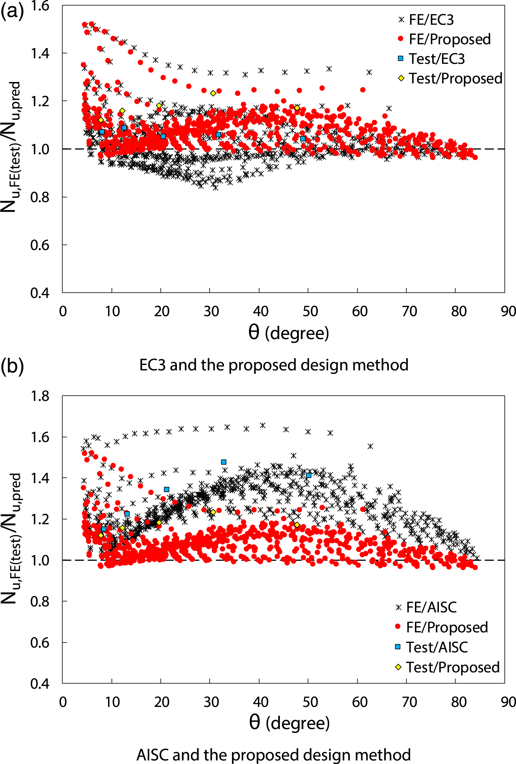
In addition, the ratios of Nu,FE(test)/Nu,pred,csm are plotted against a radial angle parameter θ in Figures 20 and 21 for welded I-sections under compression plus major and minor axis bending, respectively, in order to examine the influence of the applied loading combination (i.e. the ratio of the applied axial compression to bending moment) on the ultimate resistance predictions using the different design methods. The radial angle parameter θ is defined by equation (30) and illustrated in Figure 19, which describes the combination of axial compression load and bending moment. In equation (30), NRd and MRd are respectively the cross-sectional compression and bending resistances predicted using the different design approaches. According to this definition, θ = 0° and θ = 90° correspond to pure bending and pure compression, respectively. It can be seen from Figures 20 and 21 that the proposed design method provides the highest degree of accuracy and consistency in the resistance predictions for both NSS and HSS welded I-sections subjected to different loading combinations (i.e. 0° ≤ θ ≤ 90°). The proposed design method, however, still provides conservative resistance predictions, especially for very stocky welded I-sections, as indicted in Figure 18; this is due primary to the fact that the strain hardening is not fully exploited for very stocky welded I-sections since an upper bound to the strain limit of εcsm/εy = 15 (i.e. Ω = 15) is imposed. This strain limit could, however, be relaxed, especially for NSS structural elements, which exhibit good ductility, resulting in less conservative resistance predictions (Fieber et al., 2020; Yun et al., 2018b, 2020). Graphical definition of the radial angle parameter θ used for the assessment of design methods. Assessment of accuracy of different design methods for welded I-sections under compression plus major axis bending (date arranged with respect to the radial angle parameter θ). Assessment of accuracy of different design methods for welded I-sections under compression plus minor axis bending (date arranged with respect to the radial angle parameter θ).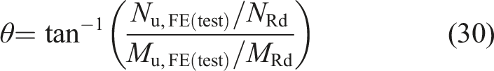
Reliability analysis
The reliability of the existing (i.e. EC3 and AISC) and proposed CSM-based design methods for NSS and HSS welded I-sections under combined compression plus uniaxial bending is assessed in this section following the procedure given in Annex D of EN 1990 (2002). The material overstrength, i.e. the mean-to-nominal yield strength ratio, were taken equal to 1.20 for S355 steel, 1.15 for S460 steel and 1.10 for S690 and S960 steels, with the corresponding COV values equal to 0.050 for S355 steel, 0.045 for S460 steel and 0.035 for S690 and S960 steels, according to prEN 1993-1-1 (2019). The COV of the cross-sectional area VA was calculated using the variability parameters of the basic cross-sectional dimensions (H, B, tf and tw) following the procedure outlined in (Afshan et al., 2015), which is, on average, equal to 0.02 for the investigated welded I-sections.

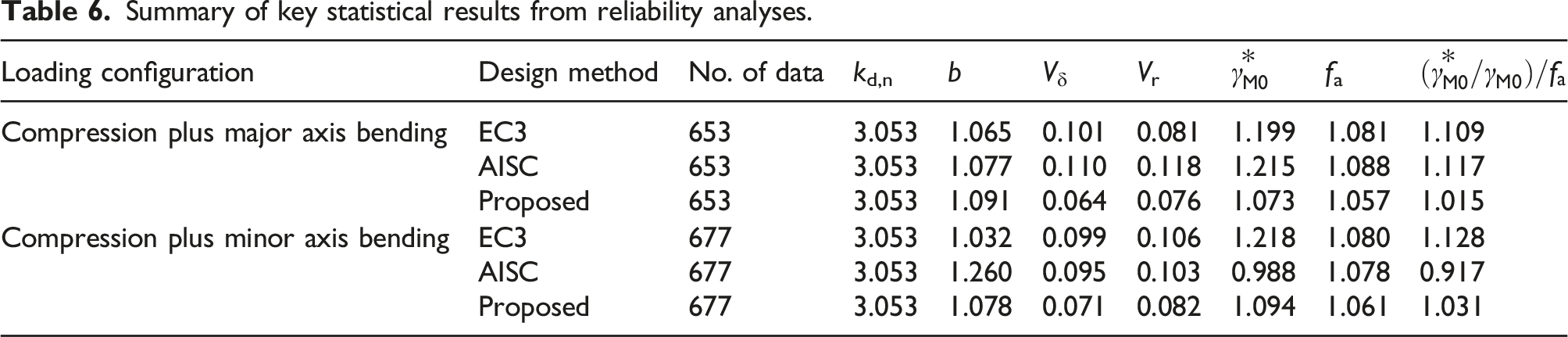
Summary of key statistical results from reliability analyses.
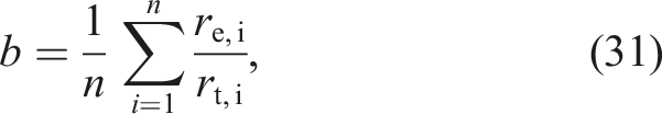
Note that the correction factor b is defined as the average of the ratios of the experimental or numerical resistance re,i to the theoretical resistance rt,i to prevent b being biased towards the experimental or numerical results with higher failure loads (Afshan et al., 2015; Meng et al., 2020), which is different from the least squares method specified in Annex D of EN 1990 (2002). A detailed description of the calculation of these key statistical can be found in (Afshan et al., 2015; Yun et al., 2022, 2022a).
It can be seen from Table 6 that the required partial safety factors
Conclusions
The cross-sectional behaviour and design of NSS and HSS welded I-sections, made of steel grades varying from 355 MPa to 960 MPa, subjected to combined compression and uniaxial bending have been numerically investigated in this paper. FE models that can accurately replicate the structural response of welded I-sections under combined loading were created and validated against experimental results collected from the literature. The validated FE models were subsequently used in parametric studies to generate extensive numerical results considering a wide range of cross-section geometries, steel grades and loading combinations. A total of 1320 numerical data were derived; these numerical data, combined with the existing test results, were utilised to evaluate the accuracy of the existing European (EC3) (2005, 2007, 2019) and North American (AISC) (2016) design methods for NSS and HSS non-slender welded I-sections subjected to compression plus uniaxial bending. The assessment revealed that both the EC3 and AISC design methods yield scattered and somewhat inaccurate resistance predictions, due primarily to the omission of strain hardening in predicting the cross-sectional compression and bending resistances (i.e. the endpoints of the interaction curves) and the shapes of the interaction curves themselves. New design proposals, based on the CSM for the calculation of the end point resistances, together with newly developed interaction curves, were proposed. The new design proposals were shown to yield more accurate and consistent resistance predictions for both NSS and HSS welded I-sections under combined loading than the existing codified methods of EC3 and AISC. Finally, reliability analysis was performed on the different design methods according to Annex D of EN 1990 (2002), indicating that the new design proposals generally provide a higher level of reliability than the current codified design approaches.
Footnotes
Declaration of conflicting interests
The author(s) declared no potential conflicts of interest with respect to the research, authorship, and/or publication of this article.
Funding
The author(s) disclosed receipt of the following financial support for the research, authorship, and/or publication of this article: This project has received funding from the Research Fund for Coal and Steel under grant agreement no. 743504.