
Abstract
This study examines experimentally the mechanical performance of composite steel and concrete beams with expansion joints in the concrete slab. Four composite beams with expansion joints in the concrete slab were tested, and various aspects of such beams including the effects of expansion joint locations (
Keywords
Introduction
Expansion joints are extensively used in civil infrastructures, such as buildings and bridges. Depending on their functions, expansion joints can be classified into construction joints, connection joints, and expansion joints, etc. Expansion joints are movement joints, which are used to allow the structural components to freely expand to accommodate the movements of structural members in service conditions. Movement in members of civil engineering structures can be due to different reasons, such as thermal effects of the environment, concrete shrinkage and creep, dynamic loading, and settlement and subsidence, etc., in either construction or service lives of civil infrastructures. In engineering practice, the contributions of those structural members on the global behavior of the structural system are generally ignored if expansion joints are used, due to the lack of sophisticated design guidelines. Such design assumptions are usefully to simplify the design and provide an additional safety margin for civil infrastructures but will cause difficulties in structural health assessment and management in real service conditions. One typical example is the bridge accessory structures, the contributions of which to bridge rigidity and load-carrying capacity is generally ignored in the design. In the authors’ former study (Lin et al., 2015), the effects of expansion joints in accessory structures in bridges including the reinforced concrete (RC) parapets, track slabs, and service ducts, etc., are investigated through a case study of a high-speed railway bridge in Japan (or Japanese Shinkansen), and the significant contributions of accessory structures on the bridge rigidities (33%–60%) were confirmed through the field measurements.
Composite steel and concrete structures have been widely used in civil infrastructures (e.g. bridges or buildings) owing to the advances of combining these two different materials compared to traditional steel or concrete structures. In composite structures, expansion joints can be used in the concrete slabs to provide relief for the tensile stresses and prevent cracks. In practice, the severe crack in the concrete slab may behave like an expansion joint as well. For continuous beams, the composite section needs to resist a large negative bending moment in the intermediate support zones (Lin et al., 2014). As the concrete slab is in tension, severe cracks may occur and acts like an expansion joint in the concrete slab.
The importance of expansion joints in concrete members has been long recognized by structural engineers, and its design methods have been investigated by many researchers. Recent studies and development in design guidelines of expansion joints are focused on expansion joints for temperature load for concrete structures (Rabbani et al., 2020; Sydnaoui et al., 2019), effects of expansion joints in deck parapets on cracking of box girders (Li et al., 2021), and dynamic response of expansion joints (Sujatha and Kumar, 2016). However, as pointed out by Fisher (2005), although “adequate provision shall be made for expansion and contraction appropriate to the service conditions of the structure” is required by the LRFD Specification (AISC, 1999), the necessary number and proper locations of expansion joints as well as their effects on the global behavior of a structure have not yet been fully understood. This study, therefore, aims to examine the structural behavior of composite steel and concrete beams with expansion joints in the concrete slab. To be specific, this research is performed to (1) study the influences of expansion joints at various locations and different sizes (through and half-through the concrete depth); (2) investigate the structural behavior of steel-concrete composite beams with discontinuous slab under different loading conditions (positive or negative bending moment); (3) examine the behavior at shear connectors located on or near the joint sections; and (4) examine the current design specifications and design assumptions that often used in the design practice with the actual measured results. The results from this study can be used to understand the structural performance of such composite beams in both elastic and plastic stages, which can provide useful information for improving the structural design and structural health assessment methods for structures or structural members with joints in their concrete slabs.
Experimental program
Test specimen
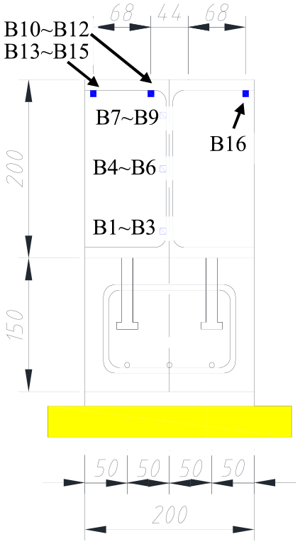
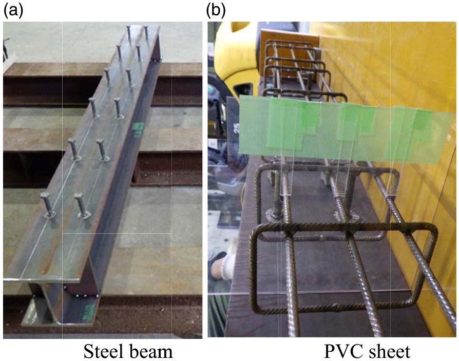
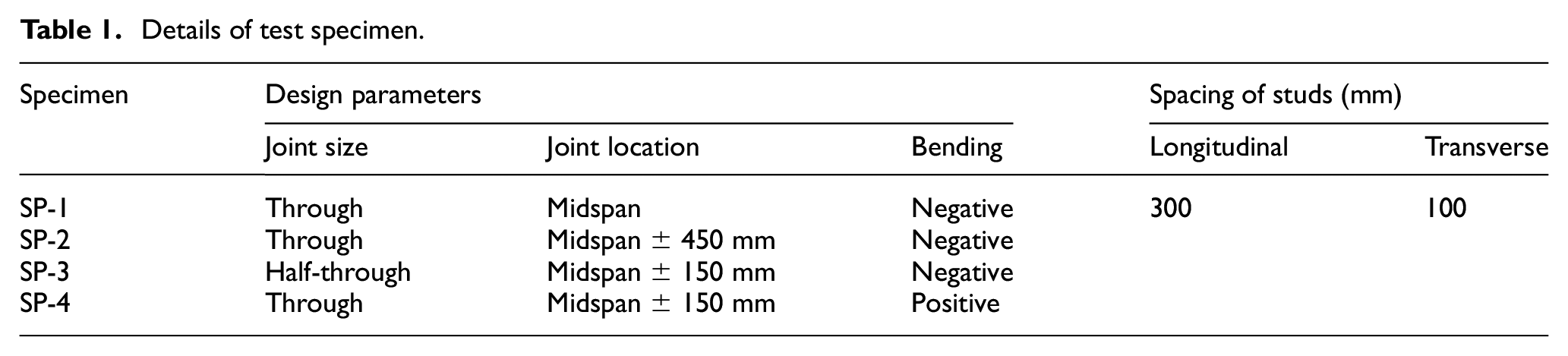
Four steel-concrete composite beams (denoted as SP-1, SP-2, SP-3 and SP-4) with expansion joints in their concrete slabs were designed and built in this study. The total length of the specimen was 2.0 m, and it was simply supported in the loading test with a span length of 1.8 m. The geometry details and typical cross-section of test specimens are illustrated in Figure 1 and Figure 2 respectively. H-shaped steel section H200×200×8×12, in which the height, the width, the web thickness, and the flange thickness are 200 mm, 200 mm, 8 mm, and 12 mm respectively, was used for the steel beam. To avoid possible buckling of the web before flexural failure, the stiffeners were used at support sections in the steel beam. Figure 3(a) shows the steel beam with headed studs before the casting of the concrete. The thickness of the concrete slab is 150 mm, and the width is 200 mm. In this experiment, the specimens are designed to examine the effects of expansion joints (e.g. stress concentration) on the steel girder. Therefore, special attention was given to the thickness, but not the width of the concrete slab. Also, the stiffener was not used at the loading point for the negative moment test specimens, as it may affect the stress distribution on the steel girder. The nominal diameter of the reinforcement is 6 mm, and it was used for both main reinforcement and stirrups inside the concrete slab. The headed studs are used as the shear connector between the steel beam and reinforced concrete (RC) slab, and their height and nominal diameter are 80 mm and 13 mm, respectively. The headed studs are placed uniformly at a spacing of 300 mm. Detailed summaries of the specimens are given in Table 1.
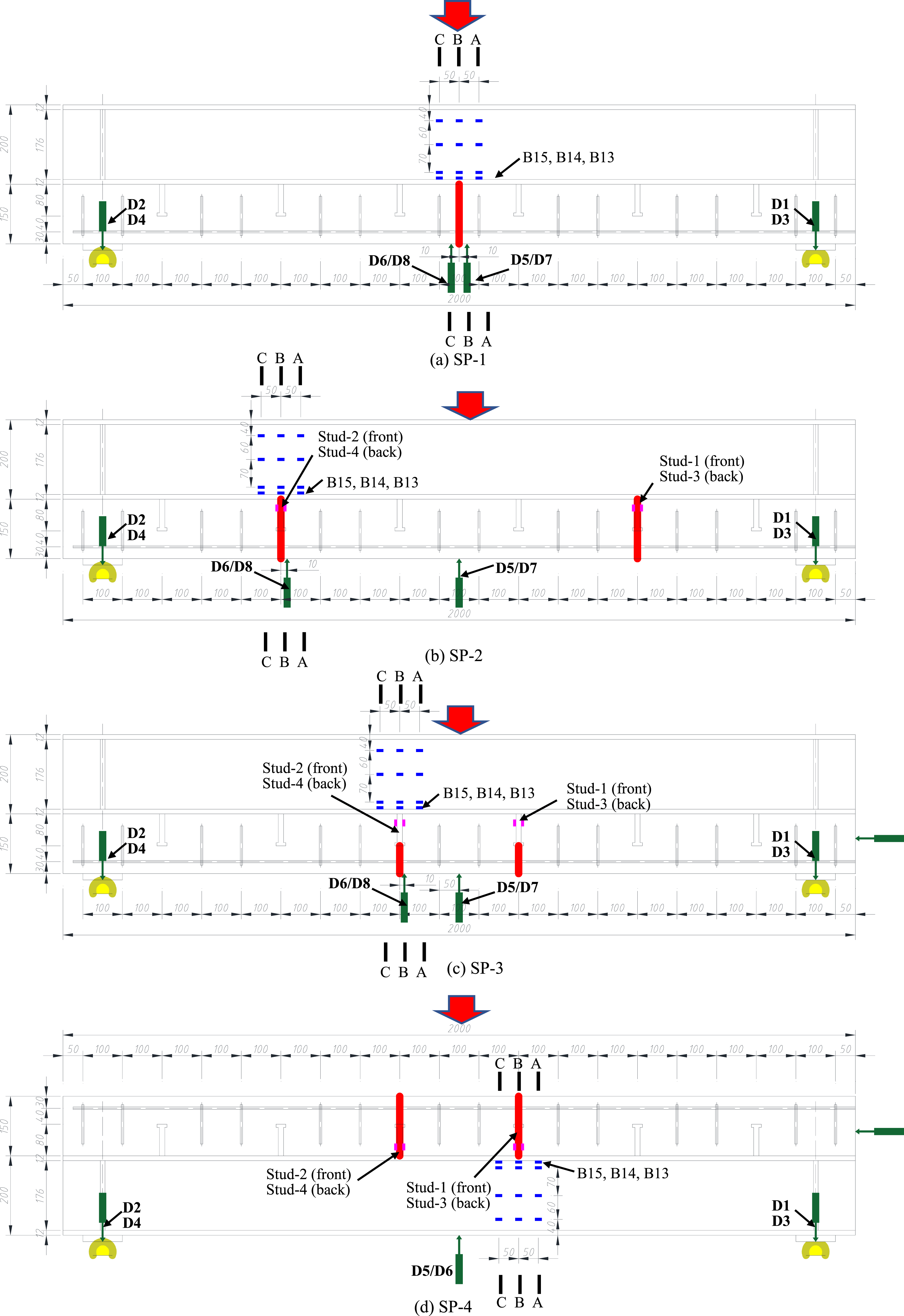
Size dimensions of the specimen and arrangement of LVDTs and strain gauges (unit: mm).
Cross section (unit: mm).
Expansion joint in specimen.
Details of test specimen.
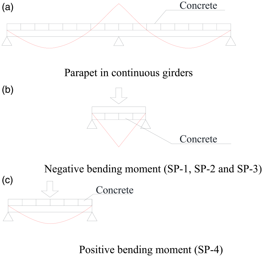
In this study, the artificial expansion joints reproduced by making a slit with a PVC sheet (thickness=10 mm) during casting of the concrete, as shown in Figure 3(b). The expansion joint penetrates without cutting the reinforcing bar. In this study, three specimens (SP-1, SP-2, and SP-3) were tested under a negative bending moment, and one specimen (SP-4) was loaded under a positive bending moment. To apply the negative bending moment, the test was set up to approximately simulate the composite beams near the intermediate support of a continuous beam (Lin et al., 2014). For SP-1, one through depth joint (total thickness of the concrete) was used in the midspan section, and the concentrated load was applied also at the same section to create a maximum negative bending moment at the joint section. In SP-2, two through depth joints were arranged at L/4 and 3 L/4 of the span respectively, where stud connectors are also at the same sections. In specimens SP-3 and SP-4, two joints were arranged at two sections near midspans where stud connectors are located at (5 L/12 and 7 L/12). However, it should be noted that the half-through depth joints were used in SP-3 under negative bending moment, while SP-4 uses two through depth joints and it was loaded under a positive bending moment. In this study, SP-1 is tested to investigate the effects of expansion joints on stress concentration under pure negative bending moment, SP-2 and SP-3 were tested to confirm the effects of various expansion joints sizes and locations on the global behavior of such beams and to study the shear transfer mechanism of studs at joint sections. The test on SP-4 was conducted to investigate the effects of expansion joints on the structural behavior of a composite beam under a positive bending moment. In general, composite beams under a positive bending moment are believed to be affected little by expansion joints in concrete slabs.
Material properties
The research was carried out in two stages, in which SP-1 and SP-2 were tested in the first stage while SP-3 and SP-4 were tested in the second stage of this project. As a result, although structural materials with the same grade are used, the material properties of SP-1 and SP-2 can be slightly different from those used in SP-3 and SP-4.
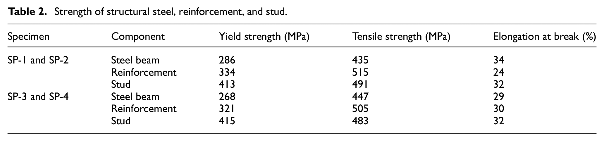
The design compressive strength of concrete is 27 MPa. Concrete cylinders (diameter=10 cm, height=20 cm) were prepared when casting the concrete and used for compressive strength tests. The loading tests on SP-1 and SP-2 were performed at 28 days after the concrete casting, while the loading tests on SP-1 and SP-2 were performed at 46 days after the concrete casting. The average compressive strength of concrete achieved on 28 days after curing was 26.7 MPa for SP-1 and SP-2. For SP-3 and SP-4, the average 28 days’ strength and 46 days’ strength were 25.6 MPa and 26.2 MPa, respectively. The structural steel SS400, with a nominal yield strength of 245 MPa and tensile strength of 400 MPa, was used for the steel beam in this specimen. The steel reinforcement made of SD295 was used for both longitudinal bars and stirrups, and it has a nominal yield strength of 295 MPa and a normal tensile strength of 440 MPa). The SS400 was also used for shear studs, whose yield strength and tensile strength are 390 MPa and 560 MPa, respectively. The yield strength, tensile strength, and elongation at break of different steel materials according to the Mill test report are illustrated in Table 2.
Strength of structural steel, reinforcement, and stud.
Instrumentation and test procedure
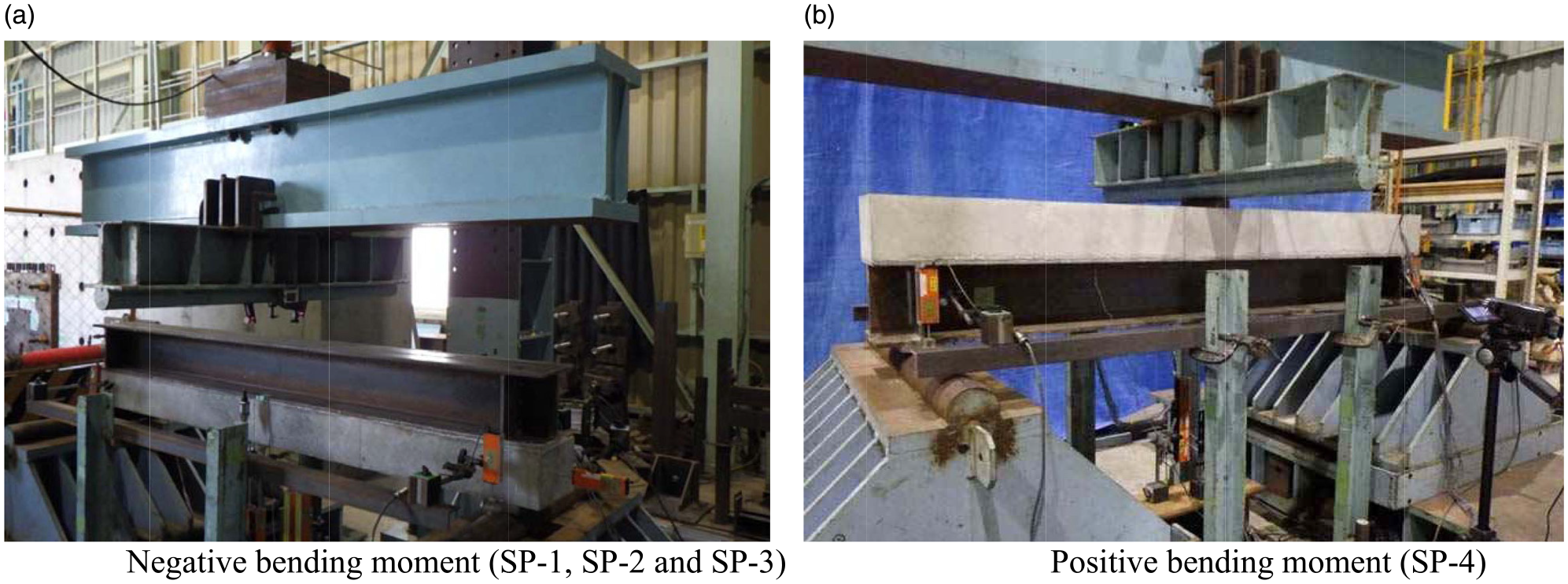
The static tests were performed by using a loading machine (loading capacity: 1500 kN) in the structural laboratory of Nippon Steel, and the setup of the specimen in the loading test is shown in Figure 4. The monotonic loading was performed, and the loading tests were terminated when the maximum load-carrying capacities of the specimens can be confirmed. The three-point bending test was conducted, and the vertical load was applied at the mid-span section to create a maximum bending moment (a negative bending moment for SP-1, SP-2, and SP-3, and a positive bending moment for SP-4).
Loading test setup.
The test specimens were instrumented to measure deflections, sectional strains across the depth of the steel beam, and strain distribution on shear connectors on or near the joint sections. To measure the sectional strain distribution, the strain on the web, and the steel flanges at or near the joint sections were measured by using 16 strain gauges (denoted as B1∼B16), as shown in Figures 1 and 2. In the loading tests, eight linear variable displacement transducers (LVDTs) were used to measure the vertical displacement at different sections including the mid-span section, joint sections, and support sections. In the loading tests for SP-3 and SP-4, another one LVDT was used at the beam end to measure the longitudinal displacement at the beam end. The detailed locations of LVDTs for each test specimen are shown in Figure 1.
The design of the loading conditions is shown in Figure 5. To simulate the negative moment area between the inflection points in a continuous beam, the composite beams (SP-1, -2, and -3) were inverted, and a concentrated load was applied on the steel girder at mid-span section of the specimen to represent the reaction forces at the intermediate support and creates a maximum negative bending moment. For SP-4, the specimen was set as a normal simply supported, and the concentrated load was applied on the concrete slab in the mid-span to create a maximum positive bending moment.
Design of the loading test.
Test results and discussions
Load versus deflection curves and load-carrying capacities
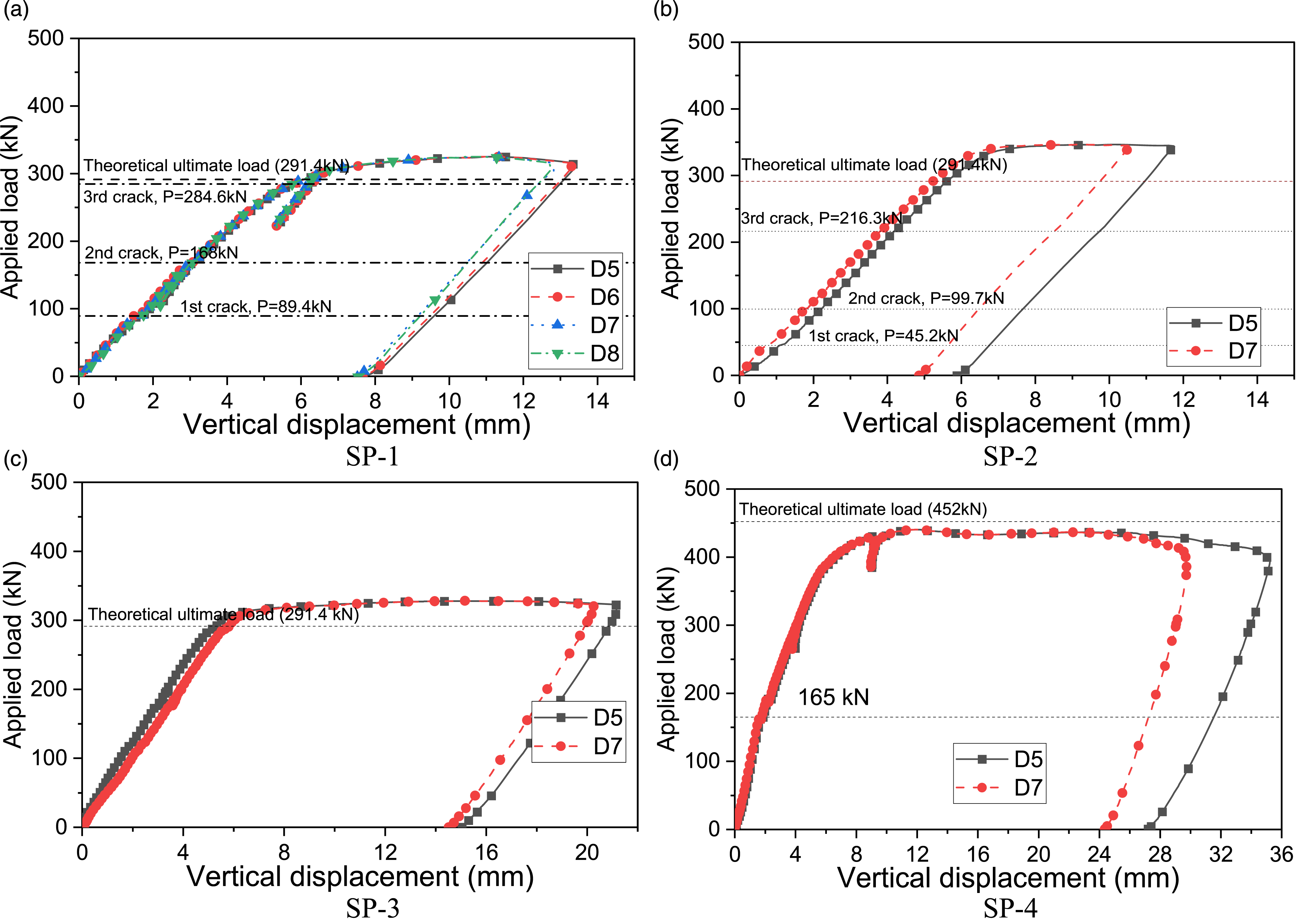
The applied load versus vertical displacement curves of the test specimens were measured in the tests and illustrated in Figure 6. The vertical displacements are taken from the bottom surface of the concrete slab near (10 mm away from the mid-span section in SP-1 due to the presence of the expansion joint) or at the mid-span section (SP-2 ∼ SP-4). The corresponding LVDT locations for each specimen are shown in Figure 1.
Applied load-deflection relationship.
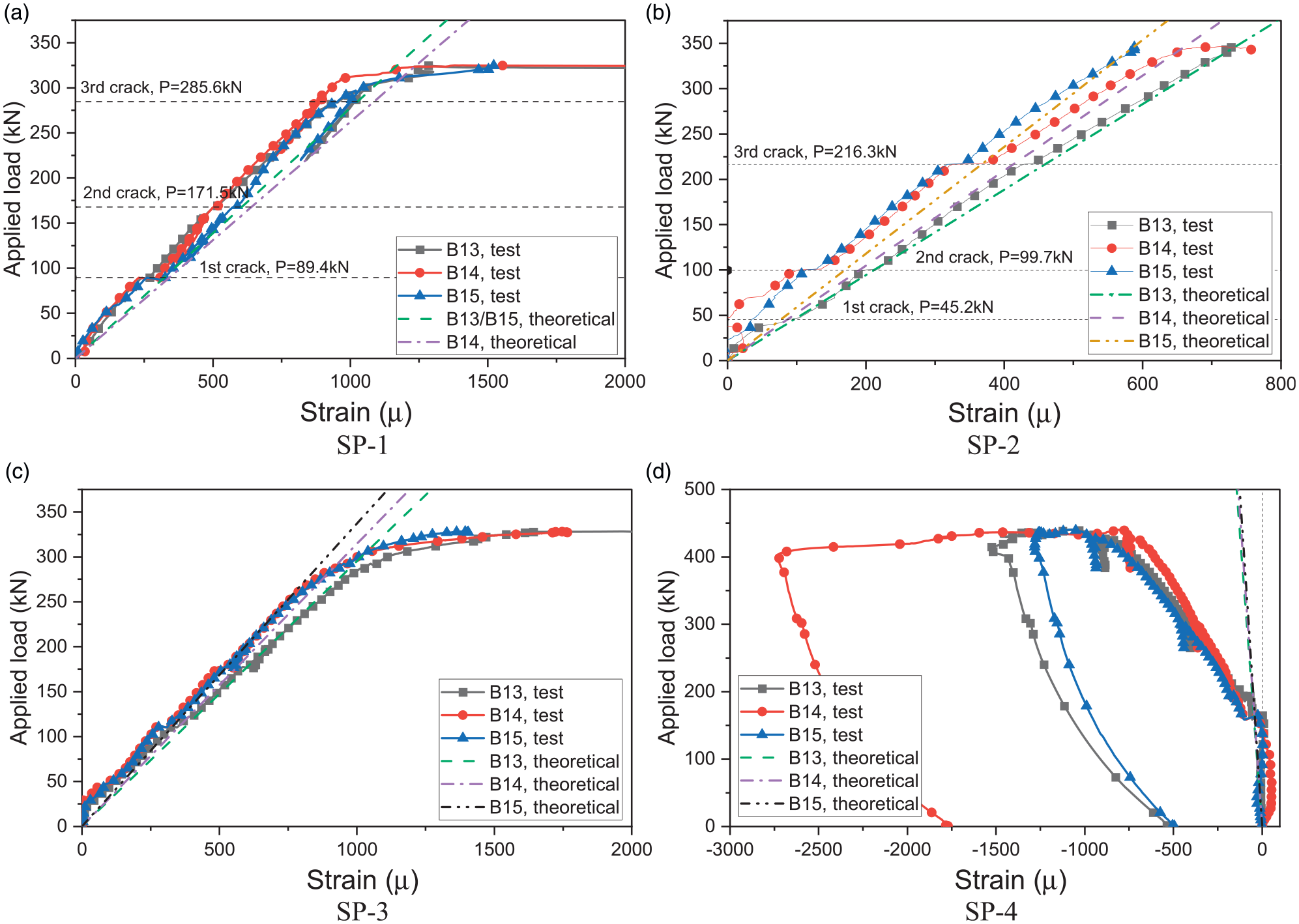
The load-displacement curves of SP-1, SP-2, and SP-3 are shown in Figure 6(a)–(c) respectively. At the beginning of the loading, the vertical displacement in SP-1 increases virtually linearly with the applied load. When the applied load was 89.4 kN, the first visible crack was observed at one side of the specimen. When the applied load increased to 168 kN, the second visible crack occurred at the other side of the specimen. The third severe crack was observed at the middle section of the specimen when the applied load was 284.6 kN. Similar to SP-1, a linear load-displacement relationship was also observed at the initial loading stage of SP-2. Thereafter, three severe cracks were also observed in the loading tests when the applied load was 45.2 kN, 99.7 kN, and 216.3 kN respectively. A resonant sound of cracking noise was produced when the first crack occurred. The cracking sequence and locations of SP-2 are shown in Figure 7(b). In both SP-1 and SP-2, a significant increase of the vertical displacement (or referred to as “displacement jump”) on the concrete slab and the reduction of the beam rigidity can be observed after the occurrence of each severe crack. The load versus displacement relationship of SP-3 is shown in Figure 6(c), which shows a similar tendency as that of SP-1 and SP-2 except that more cracks (five visiable cracks) occur on the concrete slab. As a half-through depth joint was used in SP-3, it seems the joint size can affect the cracking pattern on the concrete slab. Another interesting phenomenon from the loading tests is the similar rigidities among specimens under a negative bending moment. Taking the applied load of 151.5 kN (theoretical design yield load of the beam when reinforcing bar yields) as an example, the corresponding average displacements in SP-1, SP-2, and SP-3 were 2.76 mm, 2.90 mm, and 2.75 mm respectively. As the maximum deviation among those displacements is less than 5.5%, the rigidities of all three specimens were very close to each other. Therefore, the rigidities of the specimens were not affected significantly by the joint sizes and locations.
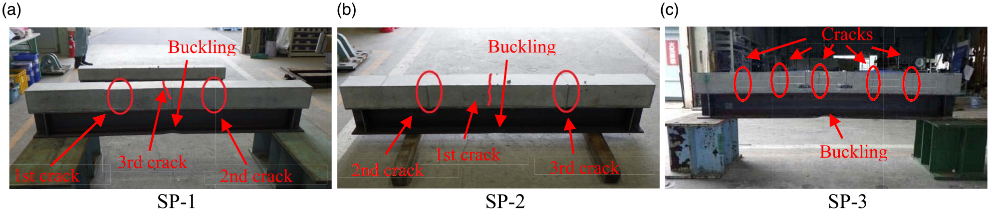
Failure mode of specimens under negative bending moment.
The load-displacement curve of SP-4 is shown in Figure 6(d). The vertical displacement increases gradually as the load increases in the beginning of the loading test, and a sudden drop in the load occurred when the applied load was 165 kN, which might be caused by the breaking failure of the steel-concrete interface. Thereafter, the beam rigidity kept decreasing as the load increase and damage of concrete slab including cracks near the support was observed during the loading test.
Table 3 shows the load carrying capacities of the test specimens obtained from the loading test. For comparison purposes, the theoretical ultimate loads of test specimens without considering the expansion joints in the concrete slab were also provided. The theoretical ultimate load was determined by
Ultimate loads of the test specimens.
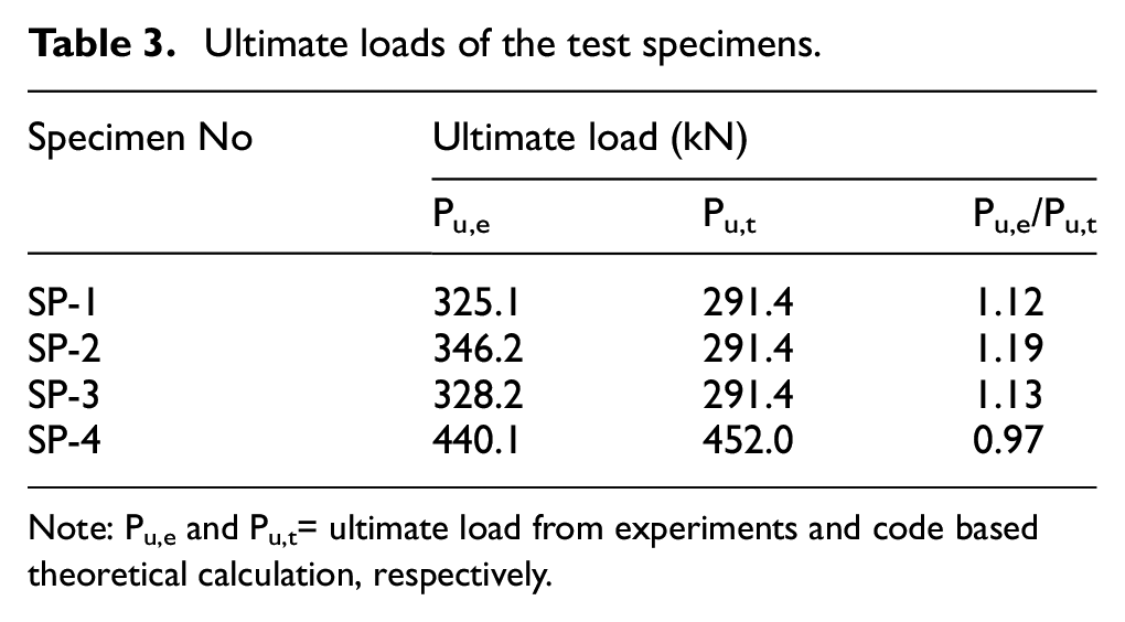
Note: Pu,e and Pu,t= ultimate load from experiments and code based theoretical calculation, respectively.
Based on the discussions above, the use of expansion joints in the concrete slab can cause changes in stiffness and discontinuity of beam curvature, which will affect the force transformation and load carrying capacities of such beams. The use of expansion joints affects more significantly on composite beams under positive bending moment than those under negative bending moment.
Failure modes of the test specimens
Three specimens (SP-1, -2, and -3) tested under negative bending moment after the loading tests are shown in Figure 7. As all three specimens are loaded under a concentrated load in the mid-span section, the concrete near this section was subjected to the maximum tensile stress. As mentioned above, three large cracks occurred during the loading test in both SP-1 and SP-2. The cracking sequence and locations of different cracks of SP-1 and SP-2 are indicated in Figure 7. In former studies on composite steel and concrete beams under a hogging bending (Lin et al., 2011 and 2015), the cracks are generally uniformly distributed on a concrete slab in the ultimate state. In this study, however, the cracks are more “concentrated”, which is the remarkable feature of the cracking pattern for steel-concrete composite beams with expansion joints in the slab. Different from those two specimens, five visible cracks were observed in SP-3. Considering the through depth joint used in SP-1 and SP-2, and the half through depth joint used in SP-3, the use of a “deeper” expansion joint tend to create more “concentrated” cracks. In the ultimate states, all three specimens reached their ultimate loads and failed by the local buckling of the steel beam at the loaded section due to the high compression caused by the negative bending moment, as shown in Figure 7.
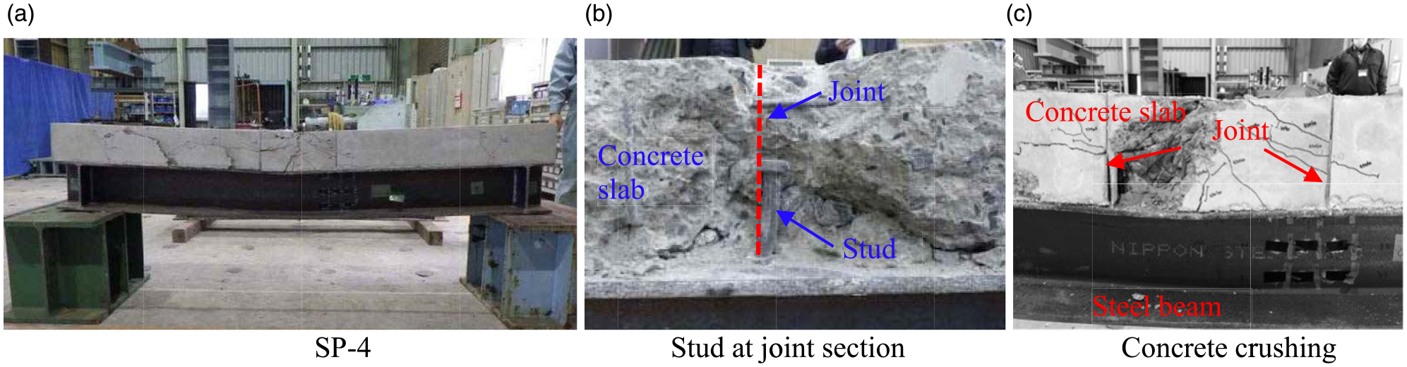
SP-4 was tested under a positive bending moment, and the specimen after the loading test is shown in Figure 8. In this experiment, special attention was given to the stud connectors. Relatively large deformation of a stud on the joint sections was confirmed in the loading test of SP-4, as can be seen in Figure 8(b). As a result, the concrete slab near the joint section suffers great damage even at low load levels. For composite beams without expansion joints in a concrete slab, the flexural failure is generally governed by concrete crushing after the yield of the structural steel, often at the loading section. When the expansion joints were used at stud sections, however, the failure of the composite beam will be governed by the crushing of the concrete near the joint or stud sections. The change of the failure mode is presumably also the cause of the decreased load-carrying capacities of SP-4 in Table 3. Special attention should be given to this aspect in the design.
Failure mode of specimen under positive bending moment.
Flexural strain on the top flange
In serviceability limit state design of structures, the methods for determining the rigidities of beams are essential. In addition, stress concentration is generally a concern when expansion joints are used in concrete members. In this study, strain gauges were arranged on the bottom surface of the top flange to measure the strain development in the loading test. Strain results at B13, B14, and B15 at Section-A, Section-B, and Section-C are reported. As can be seen in Figure 1, Section-B is the same section as the expansion joint, while Section-A and Section-C are located at both sides, which are 50 mm away from Section-B.
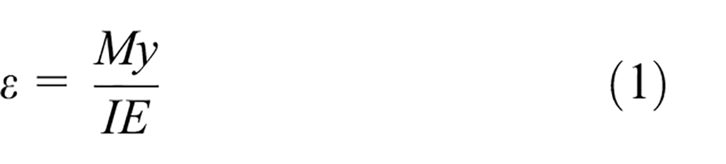
In addition to the test values, the theoretical values of flexural strain on measured locations were also provided. The theoretical values were determined using the transformed area method and the classical beam theory equation of equation (1), in which
The following assumptions are used for determining the moment of inertia
The comparisons between test results and the theoretical values of all specimens are shown in Figure 9. For beams subjected to negative bending moment (SP-1, SP-2, and SP-3), the theoretical values are on the safe side (conservative) and agree well with the measured results until the yield of the specimens. The neglected concrete tensile strength can cause a slight difference between the measured and theoretical values in the initial loading stage (e.g. SP-2 and SP-3) but can provide a conservative and reasonable prediction of the beam rigidity before the yield of the beams. For the beam under a positive bending moment (SP-4), the comparison in Figure 9(d) indicates that the assumption proposed above works well for predicting the strain until the damage of the slab occurs. Thereafter, however, the assumption becomes invalid due to the significant decrease of both rigidity and load-carrying capacity.
Longitudinal strain development on the top flange of a steel beam.
In addition, the comparisons show that the strain at B14 is similar to those at B13 and B15 in all specimens and no obvious stress concentration was observed. Continuous reinforcement is presumably the main reason. However, possible stress concentration on other structural members (e.g. reinforcement) is likely to occur and should be investigated in further studies.
Strain results of the shear connectors
Most existing studies on shear connectors are performed using push-out tests, in which the specimen was small, the number of shear connectors are rather limited, and only pure shear tests in one direction are performed (Yen et al., 1997). In the real service condition, however, the composite beams are subjected to more complicated forces including bending moment, shear forces, axial forces, and torsion, and the size of the structures and the numerical of connectors are much larger than those used in push-out tests. Especially for the test specimens in this study, some shear connectors are located at the joint section (Figure 10), and their behavior has not been investigated before.
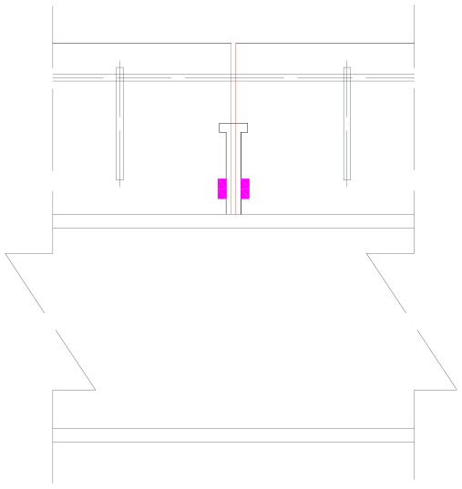
Stud at the joint section.
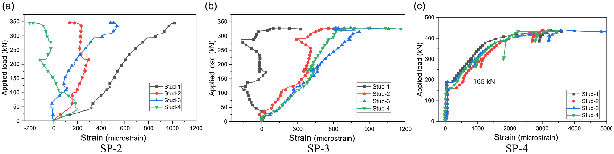
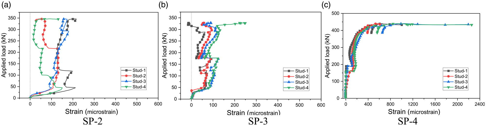
For the above-mentioned reasons, normal strain development on shear connectors at joint sections was measured in the loading test. Four studs (referred to as Stud-1∼ Stud-4) in SP-2, SP-3, and SP-4 were measured, in which the Stud-1 and Stud-3 were on one joint section, and Stud-2 and Stud-4 were on the other joint section. As shown in Figure 1, the locations of the four studs are symmetric about the beam axis. In the experiment, two strain gauges were arranged at the foot section (1∼2 cm from the top flange) of the stud to measure the compression strain

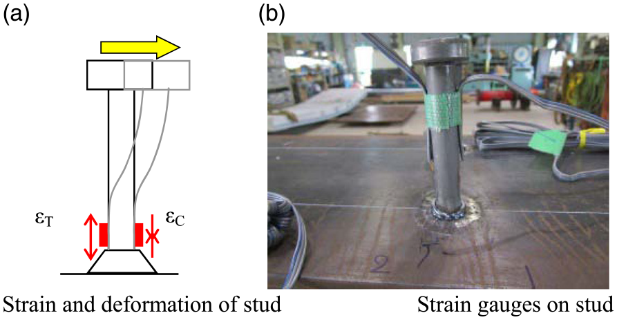
Strain measurement on stud connectors.
The bending strain results of the studs in three specimens are shown in Figure 12. The results in SP-2 of SP-3 show that the bending strain of all studs increases as the loading increase from the initial loading stage. With the loading increase, the change of bending strain becomes inconsistent among different studs. Taking studs in SP-2 as an example, bending strain of Stud-1 and Stud-2 keep increasing after the load was higher than 46 kN, but the bending strain of Stud-4 turns back and becomes smaller as the load increases. This phenomenon frequently occurs during the loading test of SP-2 and SP-3, which are presumably because of the broken bonding between the stud and surrounding concrete as well as the cracking of the concrete. For studs at joint sections, each stud is embedded by two different concrete blocks located at both sides of the expansion joint, as shown in Figure 10. For composite beams under negative bending moment, the concrete slab is in tension, resulting in the “separation” of two concrete blocks located at two sides of the expansion joints. Therefore, the forces on the stud are highly dependent on the bonding between studs and the surrounding concrete as well as the cracking conditions of the concrete slab. Also, as the maximum strain was much smaller than the yield strain (2050µ), all studs are in the elastic stage during the whole loading test.
Bending strain of studs.
The bending strain of studs in SP-4 during the loading process is shown in Figure 12(c). In the initial loading stage, the bending strain of all studs are very small, which might be due to the bonding between steel and concrete. A significant increase of the bending strain was observed in Stud-2 and Stud-4 when the load was around 165 kN. A similar increase was observed at Stud-1 and Stud-3 when the load was around 193 kN. Thereafter, the bending strain increases faster and faster as the load increase. As the measured bending strain was larger than the yield strain (2050µ), all studs are in the plastic stage in the ultimate loading state of SP-4.
The strain results of studs due to axial forces are shown in Figure 13. Overall, the axial strain versus applied load relationship looks relevant to the bending strain versus applied load relationship in Figure 12. For composite beams under a negative bending moment (SP-2 and SP-3), the axial strain of studs increased nearly linearly as the load increases in the initial loading stage. After the first crack on the concrete slab, however, the axial strain changed back and forth while the maximum strain increased little with the applied load increases. For SP-4, however, the axial strain of measured studs kept increasing in the whole loading process, and sudden strain changes (165 kN for Stud-2 and Stud-4, and 193 kN for Stud-1 and Stud-3) were also observed at the same load levels as those for bending strain.
Axial strain of studs.
The axial results of all studs are positive, indicating the axial forces are in tension in all test specimens. In addition, the axial strain of studs in all specimens is smaller than their bending strains, demonstrating that the normal strain in studs is mainly caused by the bending moment on the connectors. However, the axial strain is not neglectable compared to the bending strain and should still be considered in the design of shear connectors in such beams.
Conclusions
Four steel-concrete composite beams with expansion joints used in their concrete slabs were tested to study their mechanical behavior in both elastic and plastic stages. The experimental program was developed to study various aspects that may affect the structural performance of such beams, including expansion joint locations (
Based on the results obtained from the steel-concrete composite beams under a negative bending moment, the following conclusions are drawn:
The presence of expansion joint in a concrete slab can significantly affect the cracking pattern of the concrete slab, in which the cracks become more concentrated, but the total number of cracks becomes less. The expansion joint size can also affect the cracking pattern of the concrete slab, where the use of deeper joint can result in more “concentrated” but a smaller number of cracks.
The use of expansion joints in concrete slabs has little influence on their rigidities in the elastic stage, ultimate load-carrying capacities, as well as failure modes. The classical beam theory can be used to predict the beam rigidity in the elastic stage. The measured ultimate loads of test specimens were 12–19% larger than the conventional plastic moment in the design specifications. The current AASHTO-LRFD criterion without considering expansion joints in a concrete slab can still provide conservative estimations in calculating the load-carrying capacity of such beams under hogging moment.
The strain of studs is highly affected by the concrete slab cracking, and the strain versus load curves of studs are not stable except for the initial loading stage. The normal strain is caused by both bending moment and axial force applied on studs. The axial strain is typically smaller than that of the bending strain, and always in tension for measured stud connectors.
On the other hand, based on the results from the steel-concrete composite beam under a positive bending moment, the following conclusions are drawn:
The use of expansion joint in a concrete slab can affect their failure mode, which was the crush of the concrete near the joint section caused by the high deformation of the stud connectors.
The use of expansion joints in concrete slabs has little influence on their rigidities in the elastic stage, and the classical beam theory can be used to predict the beam rigidity in the initial load stage well. However, the measured ultimate loads of test specimens were slightly smaller than the conventional plastic moment in the design specifications, so the current AASHTO-LRFD criterion cannot be used to determine its ultimate strength. A new prediction method for the ultimate load of such beams deserves further study.
The strain versus applied load relationships of studs is more stable than the specimens under a negative bending moment. In addition, the normal strain is also caused by both bending moment and axial force applied on studs, and the axial strain is typically smaller than that of the bending strain, and always in tension for measured stud connectors.
In all tested beams, no obvious stress concentration was observed in the steel beam, which might be because the reinforcements are continuous despite the use of the joint in the concrete. In addition to the experimental results obtained in this study, other investigations using numerical analyses (e.g. specimens without setting expansion joint, or with joints at other sections) are needed to fully understand the response mechanisms of steel-concrete composite beams with expansion joints in the concrete slab.
Footnotes
Acknowledgements
The loading tests were performed at Nippon Steel Echo-Tech Corporation in Chiba, Japan. The assistance of the laboratory staff and the financial support are gratefully acknowledged.
Declaration of conflicting interests
The author(s) declared no potential conflicts of interest with respect to the research, authorship, and/or publication of this article.
Funding
The author(s) disclosed receipt of the following financial support for the research, authorship, and/or publication of this article: This work was supported by the Kajima Foundation (Japan).