
Abstract
This article compares the fire performance of axially restrained perforated carbon and austenitic stainless steel composite beams with circular and rectangular web openings. Finite element models, validated against experimental tests from the literature, were used to perform parametric analysis. The beams were analysed under various levels of load ratio and axial restraint stiffness covering the ranges which may exist in practice. It is concluded that austenitic stainless steel perforated beams show a more ductile fire response compared to carbon steel beams of similar geometry. It is shown that despite stainless steel’s higher thermal expansion, the beams exhibit lower thermal-induced peak compressive forces than carbon steel beams giving rise to lower levels of thermal-induced compressive force on the adjacent cold structures. The load ratio was found to determine the relative survivability of stainless steel and carbon steel beams, where at load ratios lower than 0.6, stainless steel beams show superior fire resistance than their carbon steel counterparts. The article also assesses the applicability and accuracy of the Steel Construction Institute method for the design of carbon and stainless steel perforated beams, and recommendations for future improvements are made.
Keywords
Introduction
Perforated steel beams are widely used in various building types such as multi-storey, commercial, industrial, warehouses and portal frames. The beams may be used with composite action, where the steel sections are attached to a composite slab by means of shear connectors, or without composite action, such as in floor beams supporting pre-cast concrete slabs. The openings in the webs of I-sections allow the efficient integration of services within the depth of the structural sections. The two main web opening configurations that are used in practice are (i) isolated large openings, with rectangular or circular shapes, which are located at discrete places where the incorporation of services is required and (ii) regular circular openings, which are also known as cellular beams.
The behaviour and design of perforated steel beams at ambient temperature have been thoroughly investigated by various experimental, analytical and numerical studies (Chung et al., 2001; Lawson et al., 1992; Liu and Chung, 2003; Panedpojaman and Rongram, 2014; Shaheen et al., 2018; Tsavdaridis et al., 2013). The presence of web openings reduces the capacity of the beam sections and introduces various complex modes of failure that may occur at or around the openings. The main failure modes of a perforated steel beam are global bending, global shear, Vierendeel bending, web-post shear and web-post buckling (Lawson and Hicks, 2011). Vierendeel mechanism is caused by the transfer of shear forces across the web openings which gives rise to secondary moments leading to the formation of plastic hinges in the corners of the Tee-sections. The Steel Construction Institute (SCI) provides guidelines for the design of composite beams with large web openings at room temperature in publication P355 (Lawson and Hicks, 2011).
At elevated temperature, the behaviour is more complex, as, together with reducing strength and stiffness of the material with increasing temperature, compressive forces due to the restrained thermal expansion, from the surrounding structure, can result in premature buckling of the Tee-section or overall distortion buckling of the beam. Fire design guidance for composite beams with rectangular and circular web openings is also provided by the SCI in publication RT1365 (SCI RT1365, 2013). However, the fire design rules provided relate to unrestrained perforated steel composite beams. The fire behaviour of restrained steel beams is significantly different to that of unrestrained beams due to the presence of high thermally induced compressive forces and the development of catenary action at high temperatures.
Najafi and Wang (2017) conducted a numerical modelling study to investigate the behaviour of axially restrained carbon steel beams with web openings at elevated temperatures. However, the study overlooked the web-post buckling behaviour, despite this being one of the main observed failure modes during the experimental tests (Najafi and Wang, 2017), which could overestimate the predicted limiting temperatures. Elsawaf and Hassan (Elsawaf and Hassan, 2018) carried out a finite element modelling investigation on restrained structural sub-assemblies of steel beams with web openings under fire. The axial restraint of the beams was provided by the column stiffness (i.e. a constant axial restraint was considered with various web opening configurations). However, the previous studies were conducted on non-composite steel beams, and their conclusions cannot be directly applied to composite beams which are most widely used in engineering practice.
Stainless steel beams, with and without web openings, and profiled decks are increasingly considered in modern composite construction practice for their corrosion resistance in visually exposed applications such as in bridge decks and car parks. Additionally, stainless steels exhibit superior strength and stiffness retention at high temperatures compared to carbon steels (CEN, 2005), which makes them an attractive choice for enhancing the structural robustness during fire. In perforated steel beams, the temperature of the web-post increases at a faster rate compared to an equivalent solid beam, thus requiring more passive fire protection. However, fire protection may be damaged and detached under static and dynamic loading situations (Kodur and Amir, 2015; Wang et al., 2013), which is most likely to occur in locations of high deflection, for example, during the catenary phase, leaving the beam exposed to the fire. Since the survivability of the beam in fire largely depends on the ability of the material to retain its mechanical properties, including strength, stiffness and ductility, at high temperatures, stainless steel offers clear advantages. The fire performance of perforated stainless steel beams has received limited attention. The differences in the mechanical and thermal properties of stainless steel, compared to carbon steels, result in differences in the performance of stainless steel structures at member and system levels, and need to be investigated.
This article presents a numerical modelling investigation of the elevated temperature performance of axially restrained carbon and stainless steel (EN 1.4301) perforated beams. Validated finite element models of carbon and stainless steel perforated beams subjected to fire are developed in the finite element analysis package ABAQUS (ABAQUS, 2019). Parametric studies to investigate the effect of key influencing parameters including opening shape (circular and rectangular), load ratio and axial end restraint ratio are performed, and the obtained results are rigorously analysed and compared. Other influencing parameters such as width-to-thickness ratio of steel elements, slenderness ratio of the beam and rotational restraints at beam ends were not considered in this study. The applicability and accuracy of the SCI method provided in Lawson and Hicks (2011); SCI RT1365 (2013), for the design of both carbon and stainless steel perforated beams subjected to elevated temperatures, are assessed.
Development of FE models and validation
Description of FE models
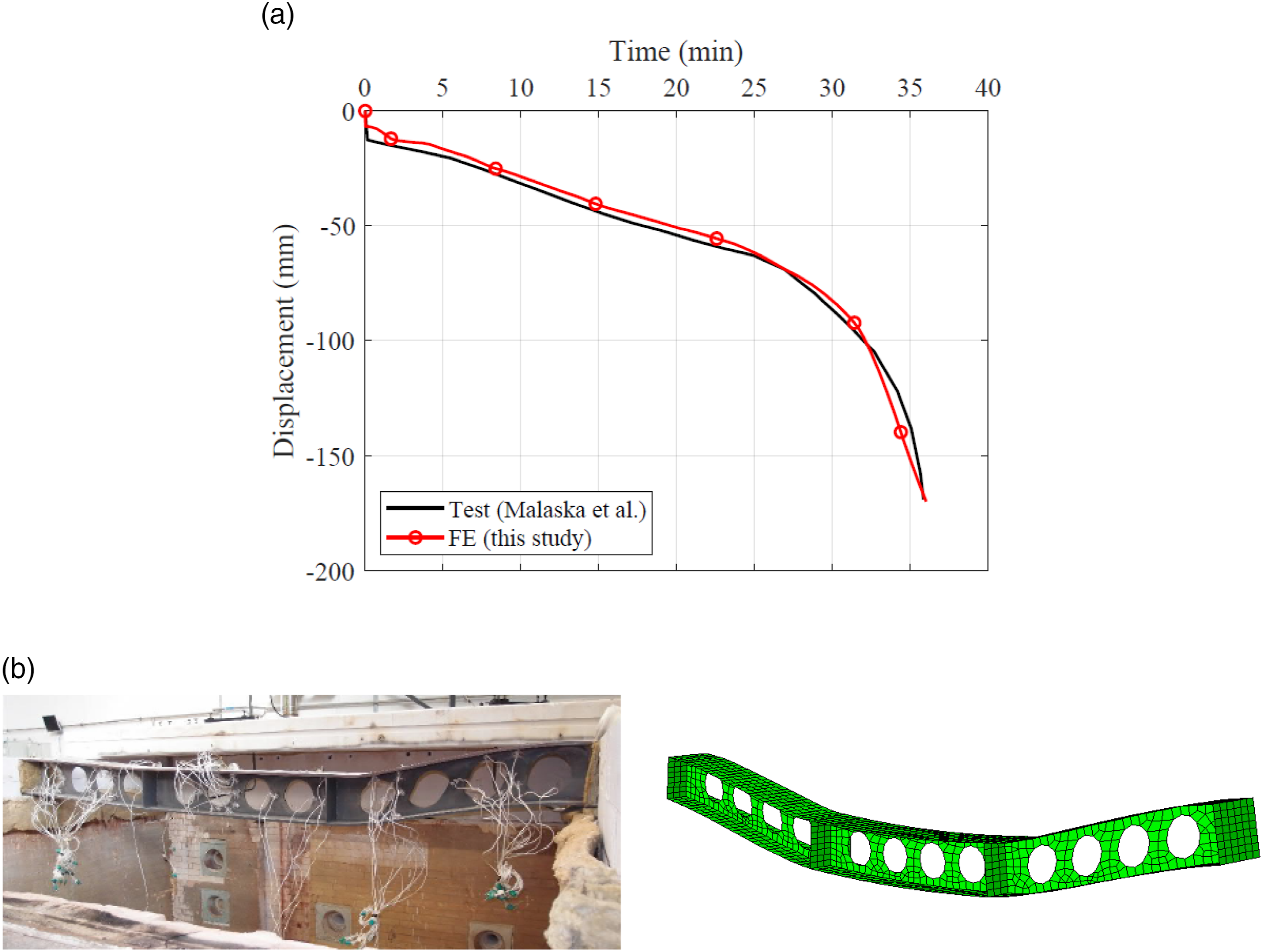
The finite element analysis package ABAQUS (ABAQUS, 2019) was used to simulate the structural response of carbon and stainless steel perforated beams subjected to elevated temperatures. The numerical model of carbon steel perforated beam was validated against the fire composite beam tests A2 and A3 conducted by Naili et al. (2011) as shown in Figures 1(a) and (b). These two beam specimens were selected based on their observed failure modes, which were Vierendeel failure for A2 and web-post buckling for A3. The fire test on the non-composite stainless steel (grade EN 1.4301) cellular beam carried out by Malaska et al. (2019), shown in Figure 1(c), was also used to validate the FE model of stainless steel perforated beam. Geometric arrangement of the simulated carbon and stainless steel perforated beams (all dimensions are in mm).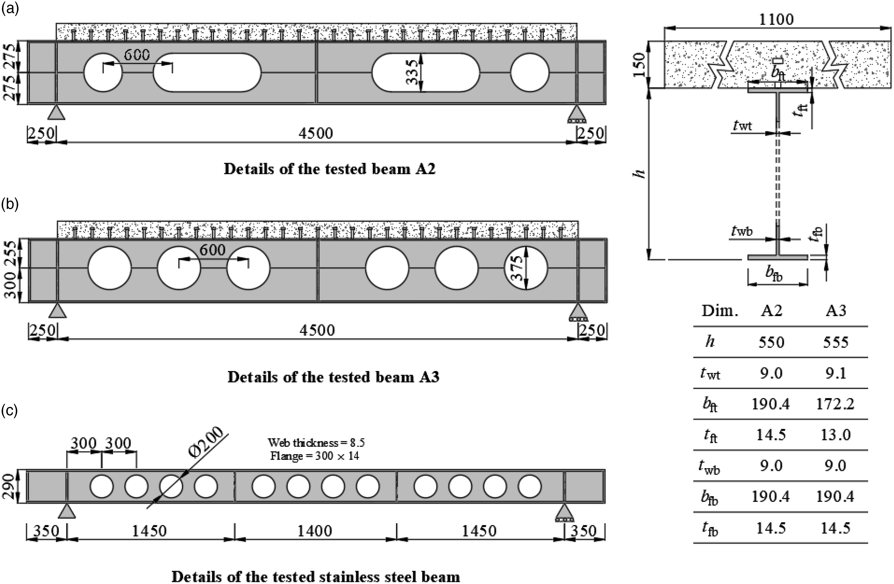
Shell elements S4R were used to discretise the steel beam, while the concrete slab was modelled by C3D8R solid-brick elements. The steel reinforcing bars were modelled as truss elements T3D2 which transmit axial tensile and compressive loads only. To simplify the mesh, the shear studs were modelled using beam elements B31 that can resist all possible straining actions. The *EMBEDDED ELEMENT technique available in ABAQUS was employed to model the interaction between the concrete slab-steel reinforcement bars and the concrete slab-steel studs. The nodal translational degrees of freedom of the embedded elements, that is, the steel reinforcement bars and steel studs, were constrained to the interpolated values of the corresponding degrees of freedom of the host elements, that is, the concrete slab.
Modelling the interaction between the concrete slab and the profiled steel deck can cause numerical instability and premature termination of the analysis (Baskar et al., 2002). Observations from experimental tests (Bailey, 2001; Nadjai et al., 2011) showed that steel deck does not significantly contribute to the overall strength of the system and its contribution to the strength can be ignored. This can be primarily because of that the steel deck loses its capacity at high temperature and that it de-bonds from the concrete due to the release of steam. Therefore, the maximum capacity is governed primarily by the degree of composite action, that is, the number of shear studs, the steel deck was not included in the developed FE models. The numerical investigations carried out by Naili et al. (2011) showed that FE models without including the steel deck can capture the behaviour of the tested composite beams. The normal contact behaviour between the steel beam and the concrete slab was defined by ‘hard contact’ in ABAQUS, which does not permit the transfer of the tensile stresses across the interface and prevents the nodes on one surface to penetrate the other surface. The interface between the slab and the steel beam was considered as a frictionless formulation and the sliding between the beam and the slab was resisted by the shear stud connection.
In the absence of reported coupon tests, the mechanical and thermal properties of the materials were defined in accordance with the provisions in EN 1994–1.2 (BSI, 1994) for concrete, EN 1993–1.2 (CEN, 2005) for carbon steel and SCI P413 (SCI, 2017) for EN 1.4301 stainless steel. The concrete damage plasticity (CDP) model was adopted to represent the concrete constitutive model as described in (Shaheen et al., 2017). The CDP model is capable of representing the concrete crushing and the formation of cracks. The compressive and tensile stress–strain behaviours of concrete were defined using the bi-linear stress–strain relationships recommended in EN 1992–1.1 (BS EN 1992-1-1, 2004). For the steel beam, the true stress σt and true strain εt, as required for modelling of shell elements, were obtained from the well-known relations εt = ln(1+εn) and σt = σn(1+εn), where σn and εn are the engineering stress and strain, respectively.
All the tested beams were simply supported (i.e. pin and roller) at their ends. Thus, in the simulations, one end of the beam was assigned fixed translational boundary conditions in the x-, y-, and z-directions while the other end was allowed to move parallel to the beam axis, x-direction only. In order to avoid restraining the moments and achieve pure hinge behaviour, the restrained surface was tied to a reference point and then the boundary conditions were assigned to this reference point. To effectively simulate the boundary condition on the roller side as in the test, a rigid plate was modelled at the roller side and a friction coefficient of 0.3 was defined between the lower flange and the rigid plate. The analysis was carried out on the imperfect model to account for initial geometric imperfections. Eigen buckling mode shapes, computed in a separate buckling analysis, were scaled and used to perturb the geometry of the FE models. From a sensitivity analysis, it was found that the magnitude of the geometric imperfection amplitude has negligible influence on the beam behaviour. Hence, the imperfection shape was taken as the first Eigen mode factored by an amplitude of tw/200 (Tsavdaridis and Galiatsatos, 2015), where tw is the web thickness.
Two analyses steps were defined to solve the geometrically and materially nonlinear problem. In step 1, the test load was applied at ambient temperature and maintained constant, following which in step 2, the test measured temperature profiles were applied to the model as a predefined field. In order to resemble the action of the loading apparatus, the applied load was distributed on the area represented by the projection area of the contact surface between the spreader beam and the concrete slab. The beams were split into different areas based on the recorded temperatures during the tests. Different temperature–time curves were introduced to the model according to the average thermocouple readings recorded in the tests as shown in Figure 2. The temperature variation was only considered across the depth of the beam and remained constant along the beam length. There was no sign of loss of composite action between the beam and the slab (Naili et al., 2011), which suggested that the shear studs performed adequately and maintained the composite action throughout the full duration of the test. Hence, no temperature profile was assigned to the shear studs. Recorded temperature–time profiles of tested carbon and stainless steel beams.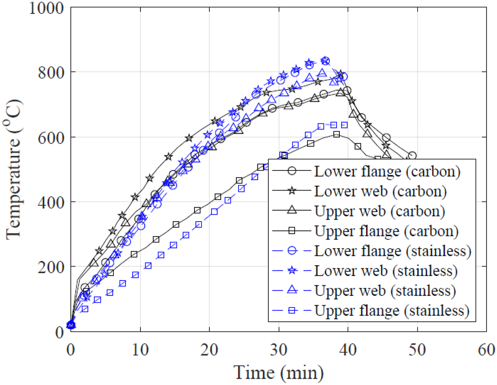
Validation results
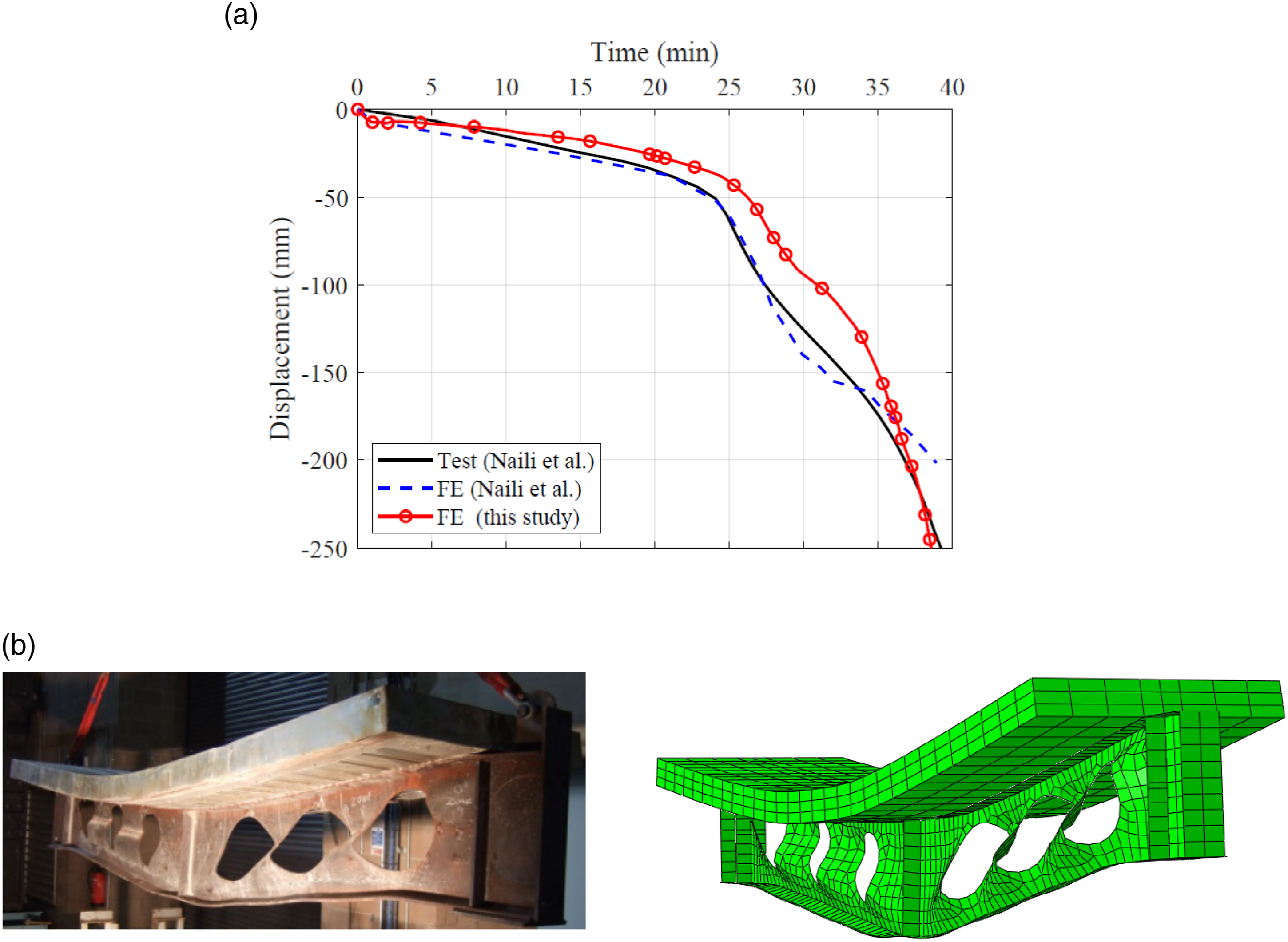
The displacement–time responses and the failure mechanisms from the test and FE models are compared in Figures 3 and 4 for the carbon steel perforated beams A2 and A3, respectively and Figure 5 for the stainless steel perforated beam. In Figures 3 and 4, the results of the FE simulations conducted by Naili et al. (2011) are also presented for comparison purposes. Comparisons of the experimentally and numerically obtained displacement–time curves and the failure modes show that the developed FE models are capable of replicating the elevated temperature large deflection behaviour of carbon steel and stainless steel perforated beams with a high degree of predictive accuracy, and hence can reliably be employed for conducting numerical parametric analysis. It should be noted that there is a slight difference between the FE and experimental tests result for test A3 (see Figure 4(a)) which may rise from the adopted material model and the absence of the temperature distribution along the length of the beam. Comparison between FE and test results for perforated carbon steel beam A2. (a) Displacement-time response. (b) Test and FE failure modes. Comparison between FE and test results for perforated carbon steel beam A3. (a) Displacement-time response. (b) Test and FE failure modes. Comparison between FE and test results for stainless steel cellular beam. (a) Displacement-time response. (b) Test and FE failure modes.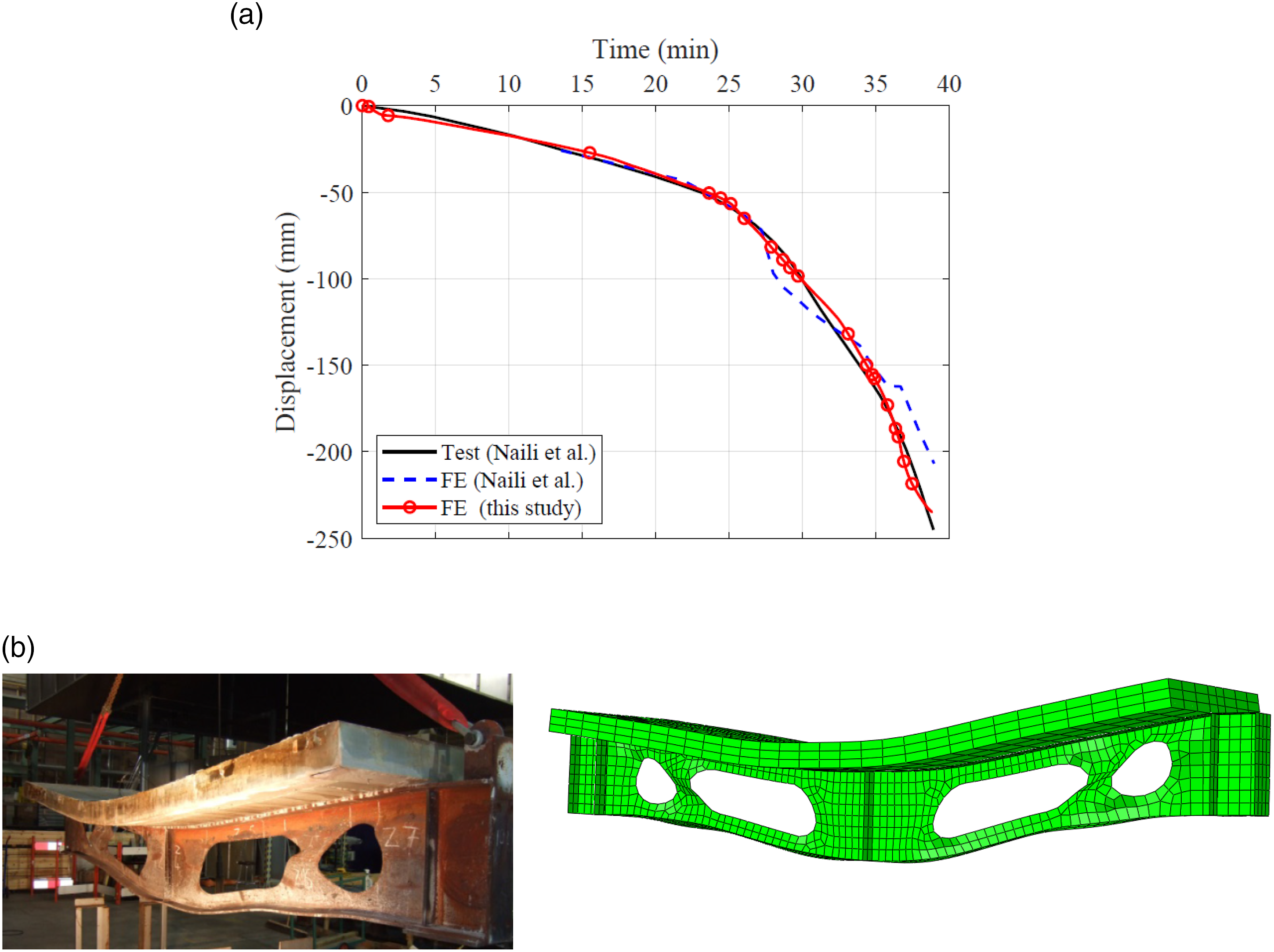
Parametric study cases and modelling assumptions
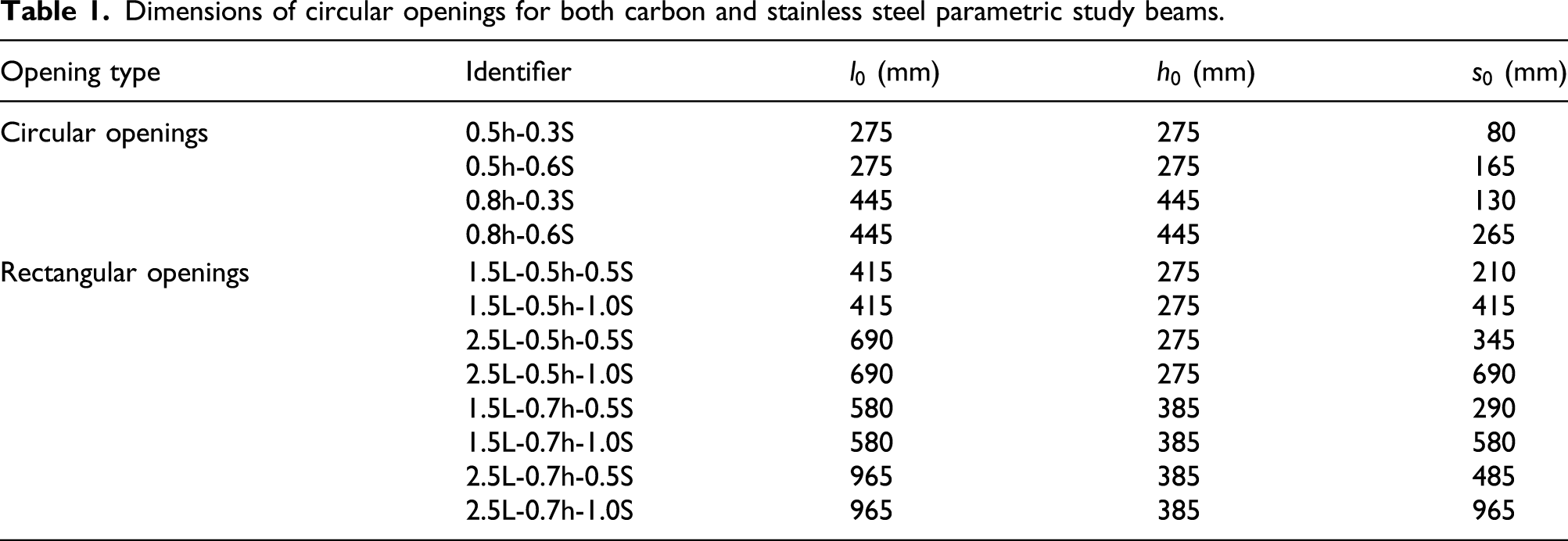
The elevated temperature response of axially restrained carbon steel and stainless steel perforated beams is investigated herein through a parametric modelling programme, which is based on the validated numerical models developed in Section 2. In this study, carbon and stainless steel beams with different circular and rectangular web opening arrangements, as illustrated in Figures 6(a) and (b), were modelled. For all the modelled beams, the cross-section of the A2 beam was employed. The dimensions of the web opening geometries of the modelled beams are listed in Table 1 for the perforated circular and rectangular beams, where l0 is the opening length, h0 is the opening height and s0 is the distance between the openings, as illustrated in Figure 6(a) and (b). The web openings are concentric with the mid-height of the beam and were without reinforcement. The selected opening configurations are in accordance with the practical geometric limits set out in Table 2.1 of the SCI guidance document Design of Composite Beams with Large Web Openings (Lawson and Hicks, 2011). Definitions of geometric parameters and specimen identifier. (a) Circular web opening. (b) Rectangular web opening. (c) The definition of parametric models specimen identifier. Dimensions of circular openings for both carbon and stainless steel parametric study beams.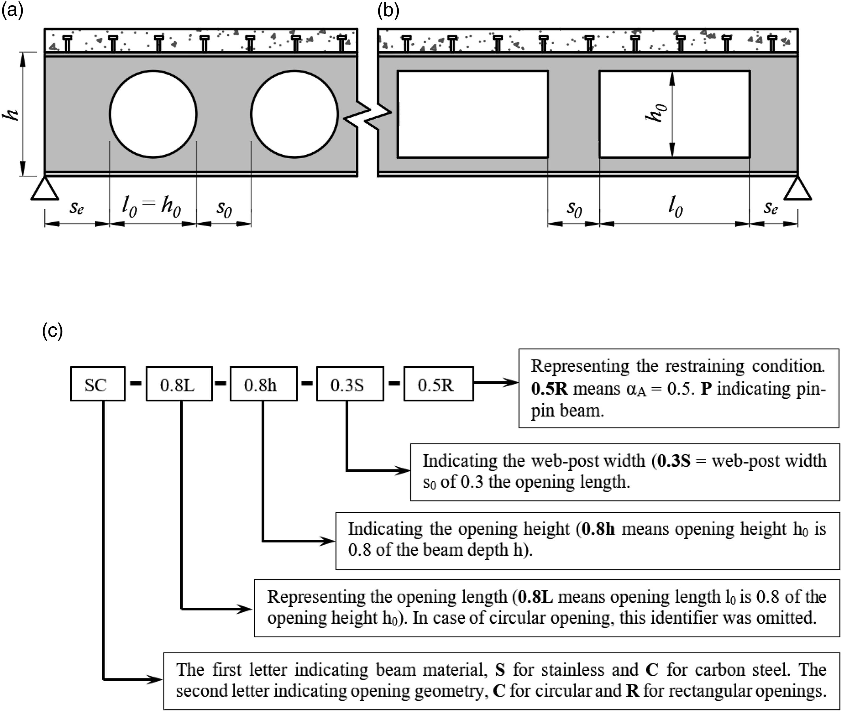
The elevated temperature response of the beams under varying levels of axial end restraints, as represented by the axial restraint stiffness ratio αA = 0.5, 1.0, 2.0 and zero (i.e. pin-roller supports) and full axial restraint (i.e. pin–pin supports), which were free rotationally, were simulated. The αA ratio is defined as the ratio of the applied end axial restraint stiffness to the axial stiffness of the beam at room temperature EA/L, where E, A and L are the Young’s modulus at room temperature, the cross-sectional area and the beam length, respectively. The axial restraints at the beam ends were modelled by means of linear elastic springs. The beams were analysed under uniformly distributed load with load ratios of 0.5 at elevated temperatures. The load ratio is defined as the ratio of the applied load at elevated temperature to the failure load of the beam with simple supports at ambient temperature, which was obtained from a prior ambient temperature simulation for each of the considered perforated beam profiles. The time–temperature profile recorded in the tests by Naili et al. (2011) was employed of all parametric models. The modelled carbon and stainless steel beams were investigated under the same temperature–time curves as the recorded temperature profiles for both materials were found to be similar as shown in Figure 2. The mechanical and thermal (thermal expansion) properties of the modelled stainless steel and carbon steel were taken as those used for the validation models.
Figure 6(c) describes the specimen designation system used throughout this article. The first identifier represents the beam material and the opening configuration, the second identifier represents the opening length, the third identifier indicates the opening height, the fourth identifier indicates the width of the beam web-post and the fifth identifier represent the ratio of the applied end restraint stiffness to the axial stiffness of the beam at ambient temperature, that is, the αA ratio. For the circular opening configurations, the length and the height of the web openings are equal, thus the second identifier was omitted. The last identifier was defined as Zero and P for the modelled beams with pin-roller and pin–pin end support conditions, respectively.
The end supports were modelled as idealised supports located at the centre of the beam web. This support location can provide a positive effect on the beam behaviour within the small vertical deflection values, when Δ (beam centreline deflection) <y (distance between beam centreline and the neutral axis) as it is shown in Figure 7, as the fire-induced bending moment is opposite to the applied bending moment. This configuration replicates the real case scenarios in which the connections are positioned with respect to the steel section. However, since the capacity of the end web-post depends on the type of end connection (Lawson and Hicks, 2011), the idealised end supports do not replicate the real end conditions of beam in terms of the developed forces in the end web-posts. Therefore, to avoid the effect of this on the beam performance, the width of the end web-post se was selected inasmuch that does not fail during the analysis. Location of end supports and fire-induced force.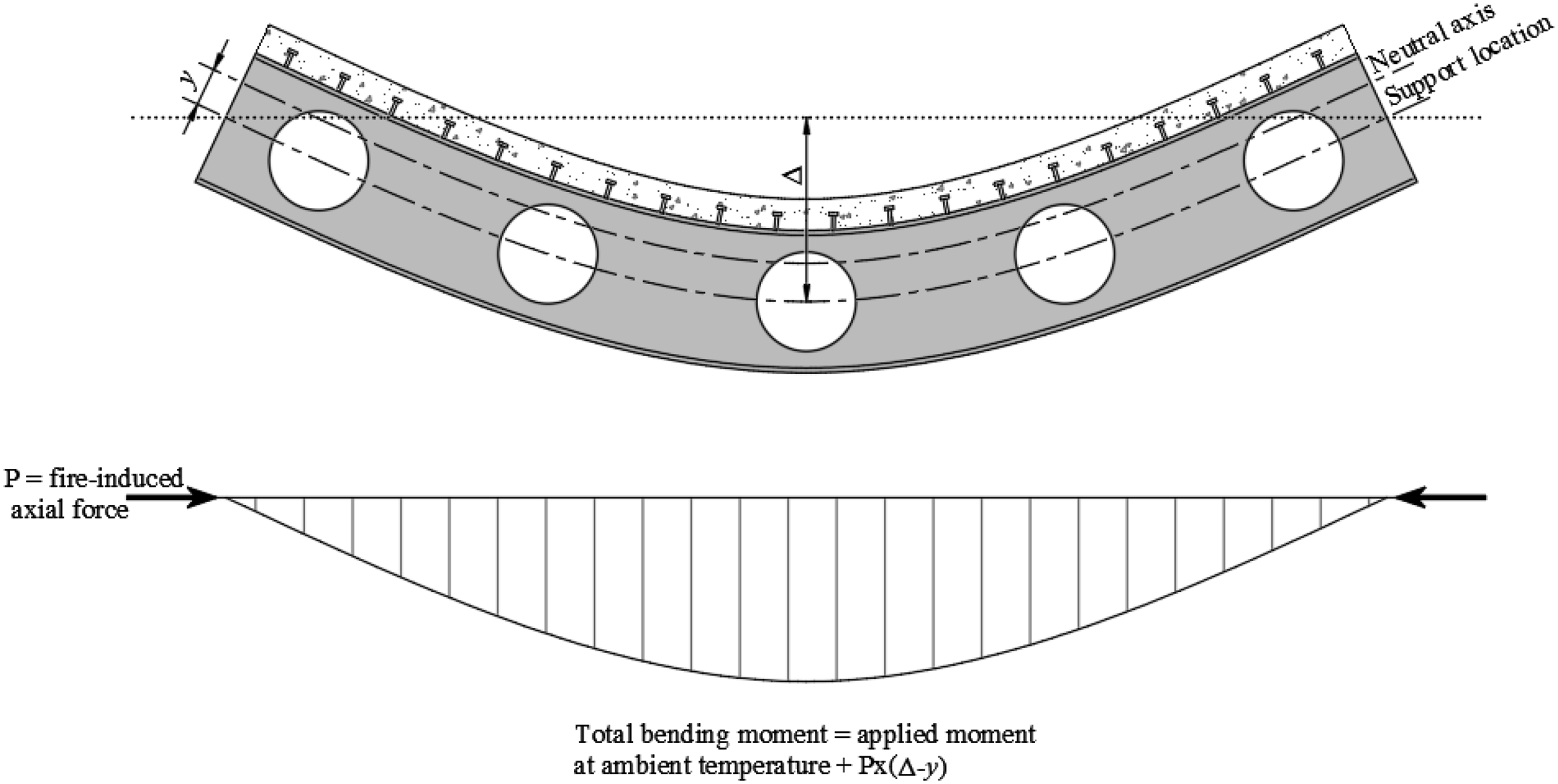
Analysis of results and discussions
Failure modes
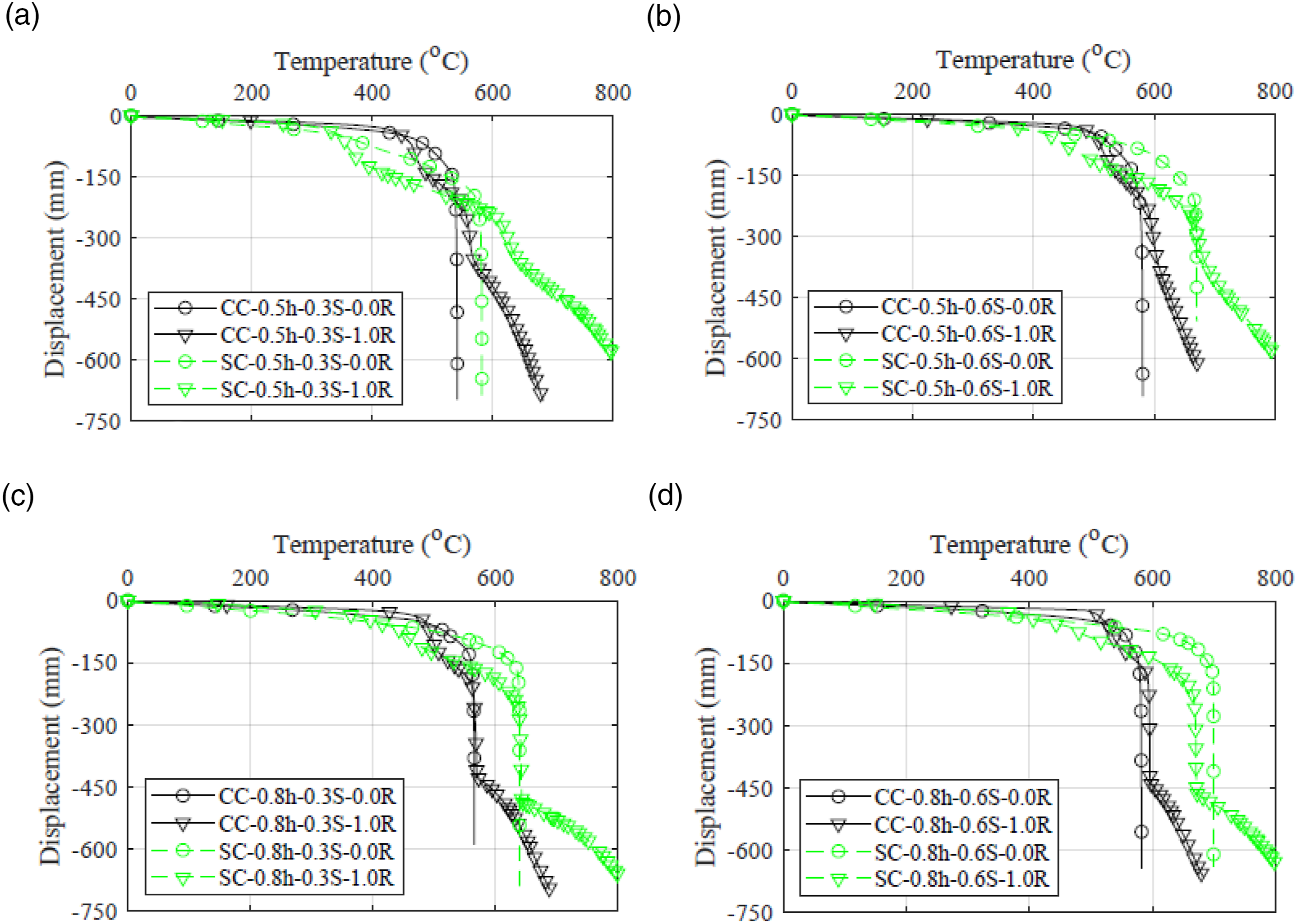
For the cellular carbon and stainless steel beams considered in this study, web-post buckling was the ultimate failure mode even though Vierendeel bending was initially observed in models with large web openings (e.g. 0.8 h). At first, buckling took place at the web-posts in close proximity to the supports due to the presence of high shear forces in those regions, which was then followed by buckling of the low shear inner web-posts as shown in Figure 8. This progressive failure mechanism, which allowed for the redistribution of the loads from the end to the inner web-posts, resulted in a nonlinear deflection response with temperature rather than an instantaneous runaway deflection as shown in Figure 9. When all the web-posts achieved their buckling capacity, runaway response of the restrained and unrestrained steel beams was observed prior to the start of the catenary phase. This load redistribution, from the high shear zone end web-posts to the low shear zone inner web-posts, means that the beam response is controlled not only by the capacity of the individual web-posts, but also the number of web-posts across the beam length and the ductility of the material. Progressive buckling of web-posts for model CC-0.5h-0.3S-1.0 R. (a) Buckling of web-posts at 480°C. (b) Buckling of web-posts at 550°C. Deflection-temperature response of carbon steel and stainless steel cellular beams. (a) h/h0 = 0.5 and s0/h0 = 0.3. (b) h/h0 = 0.5 and s0/h0 = 0.6. (c) h/h0 = 0.8 and s0/h0 = 0.3. (d) h/h0 = 0.8 and s0/h0 = 0.6.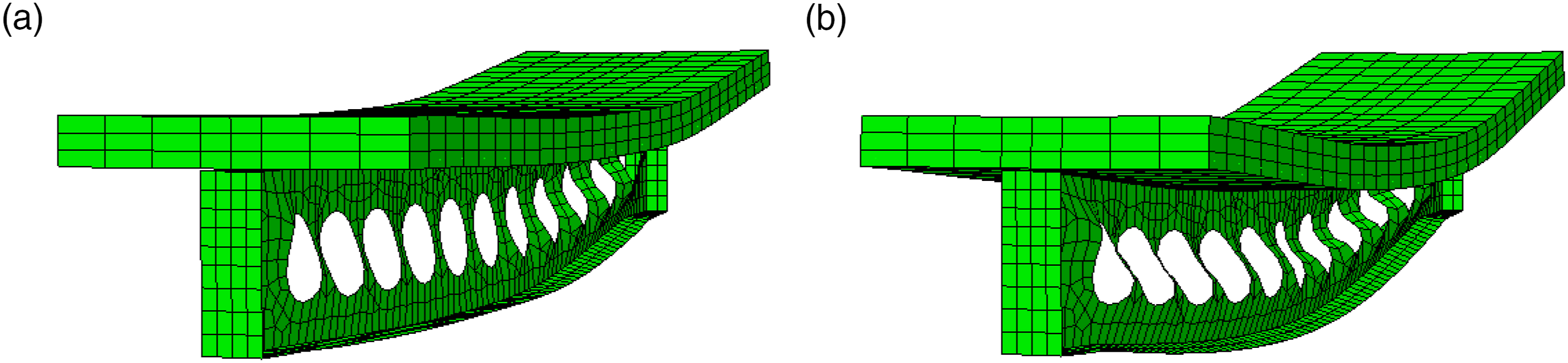
For the carbon and stainless steel beams with rectangular web openings, the above-described response characteristics for the cellular beams were also observed, with the exception of the pin-ended beams with web opening length of l0/h0 = 2.5, which experienced initial bottom Tee-section buckling, as it is shown in Figure 10(a), followed by Vierendeel bending and web-post buckling. Tee-section buckling failure mechanism of perforated beams is not included in the SCI design guidance documents (Lawson and Hicks, 2011; SCI RT1365, 2013). This failure mode is not relevant at ambient temperature as the bottom Tee-section is under tension and the top Tee-section is restrained by the composite action of the concrete slab. However, at elevated temperature, the presence of high compressive forces generated in the bottom Tee-section by the restrained thermal expansion strains could trigger Tee-section buckling failure mechanism in perforated beams. Buckling and plastic strain distribution of carbon and stainless steel perorated beams. (a) Typical bottom Tee-section buckling of carbon and stainless steel beams with opening length of 2.5h0. (b) Plastic strain distribution for arbon steel beam. (c) Plastic strain distribution stainless steel beam.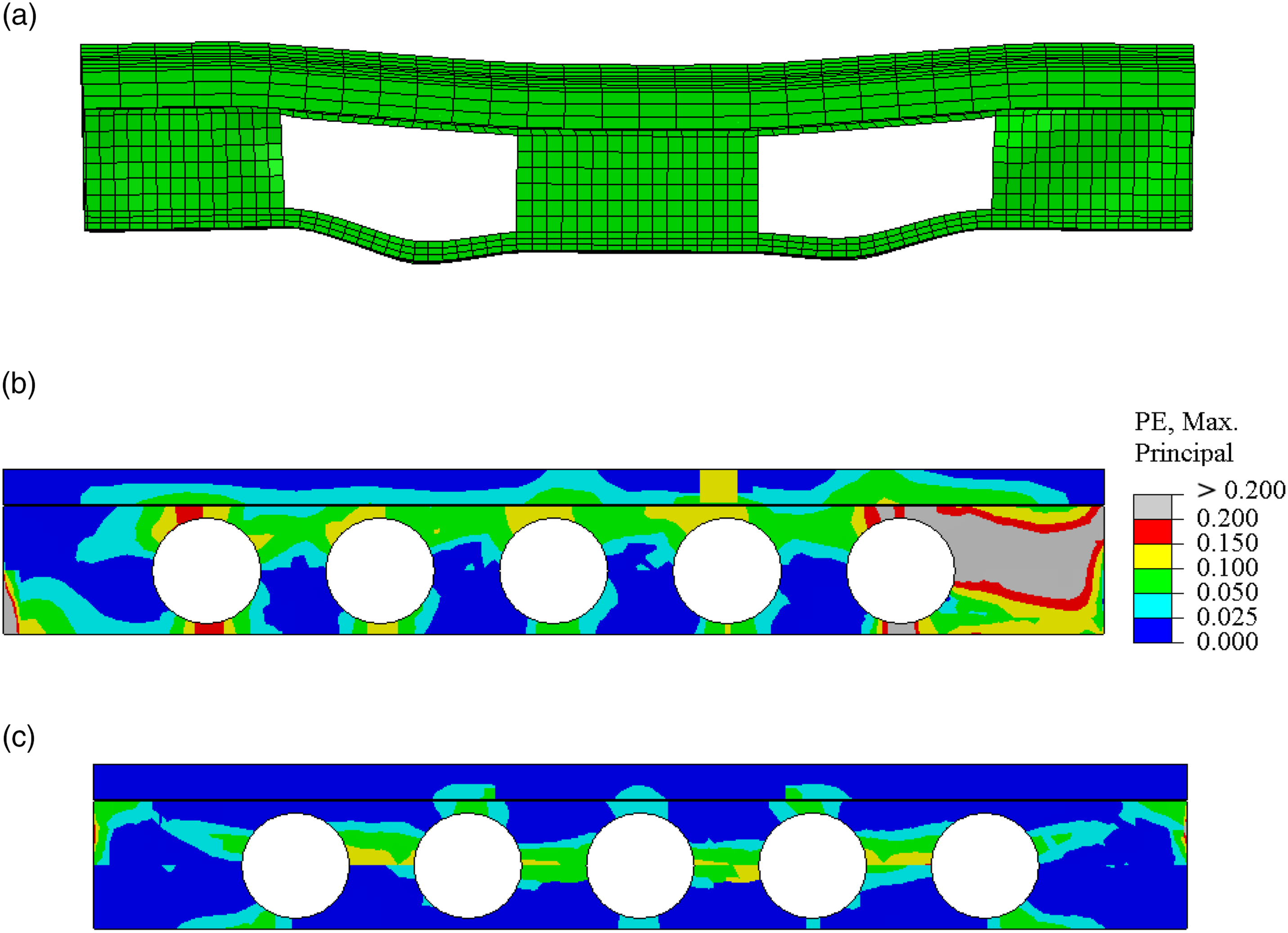
Ultimately, when the perforated beams develop high tensile stresses within the catenary phase, together with significant loss of strength and stiffness, the carbon steel beams are more likely to fail by tensile rupture, due to the limited ductility of the material, than the stainless steel beams. The rupture strain of the modelled carbon steel beams with large web openings, both circular and rectangular, exceeded the threshold value of 0.2 that is recommended by EN 1993–1.2 (CEN, 2005), while the rupture strain of stainless steel beams remained within the plastic strain range of 0.49 which is recommended by SCI P413 (SCI, 2017). Figures 10(c) and (d) compare the plastic strain distribution of carbon and stainless steel perforated beams for models CC-0.8h-0.6S-2.0R and SC-0.8h-0.6S-2.0R within the catenary phase. For all modelled beams, the stainless steel perforated beams show a more ductile elevated temperature response than the carbon steel perforated beams of similar geometry.
The composite action between the concrete slab and the beam prevented the twisting of the beam as a whole. However, it was observed that the bottom flange buckled with lateral movement as it is shown in Figure 11(a). Nadjai et al. (2011) observed similar failure mode on experimentally tested cellular carbon steel beams and classified the failure mode as ‘overall distortional buckling’ (Nadjai et al., 2011). However, investigating the FE models revealed that the bottom flange was under tensile stresses when the lateral movement was observed, indicating that this movement was associated with a local instability of the web rather than the buckling of the flange due to compressive forces. Furthermore, the unrestrained beams, in which the thermal-induced compression was absent, also experienced lateral movement of the bottom flange. Thus, this failure mode should be classified as ‘sidesways web buckling’ which is a limit state that can be experienced by a composite beam under transverse concentrated loads (Topkaya, 2006). In the case of sidesways web buckling of beams, the web tends to buckle while the bottom (tension) flange tries to restrain the movement. Therefore, this failure mode can be prevented by increasing the capacity of the bottom flange. Further analysis was carried out on a specimen identical to CC-0.8h-0.3S-0.5R, but with a higher capacity bottom flange (290.4 mm wide × 20 mm thick). Figures 11(a) and (b) compare the failure mode of the two models, where it is shown that increasing the bottom flange capacity was capable of preventing the sidesways web buckling failure mode. However, the resistance of bottom flange against lateral deflection also depends on the elastic modulus, which reduces with temperature, and also the magnitude of the lateral force posed by web-post buckling. Stainless steel cellular beams with h0/h = 0.5 and s0/h0 = 0.3 were able to prevent this sidesways web buckling failure mode as it is shown in Figure 11(c), which may be attributed to the superior retention of the elastic modulus of the material with temperature compared to carbon steel. Further investigation is required to quantify the effect of the previous parameters on the sideways web buckling failure mode. Stability of lower flange. (a) Stability of lower flange at 560°C for model CC-0.8h-0.3S-0.5 R. (b) Stability of lower flange for model CC-0.8h-0.3S-0.5 R with increased bottom flange dimensions (290.4 mm wide × 20 mm thick). (c) Stability of lower flange at 700°C for model SC-0.5h-0.3S-1.0 R.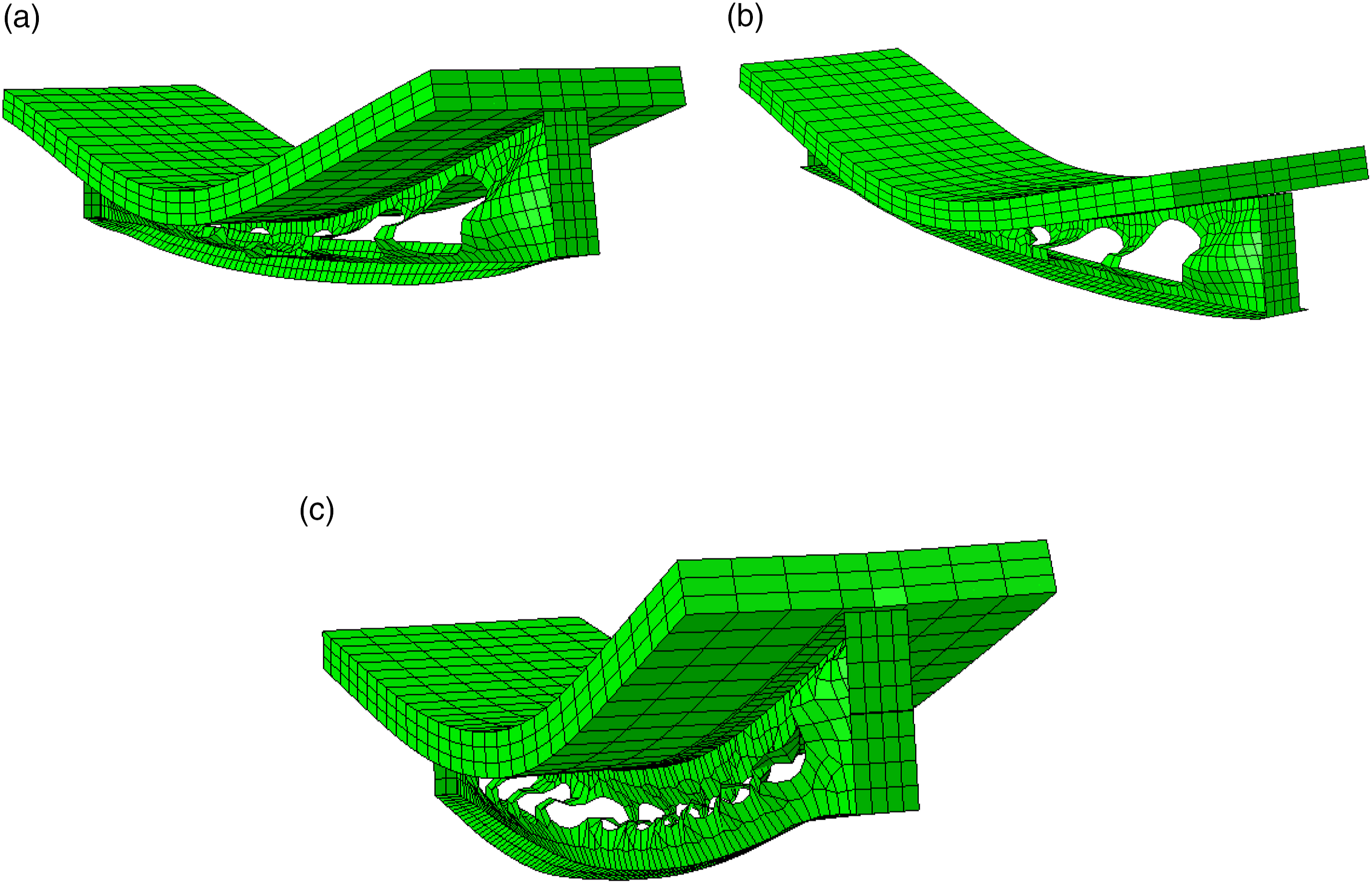
Catenary phase and peak compressive force
Both carbon and stainless steel beams were capable of developing into the catenary phase at high temperatures as it is shown in Figure 12. During the catenary phase, the compressive force gradually changes to a tensile force and, eventually, the beam supports the applied loads by catenary action rather than flexure and shear. The stainless steel beams reached their maximum tensile catenary force at higher temperatures, approximately by 100°C, than the carbon steel beams. Furthermore, the tension force in the carbon steel beams declined with temperature at a higher rate than the stainless steel beams; this is attributed to the stainless steel’s superior retention of mechanical properties at high temperatures. Comparison of the axial force-temperature responses of carbon and stainless steel cellular beams. (a) h/h0 = 0.5 and s0/h0 = 0.3. (b) h/h0 = 0.5 and s0/h0 = 0.6. (c) h/h0 = 0.8 and s0/h0 = 0.3. (d) h/h0 = 0.8 and s0/h0 = 0.6.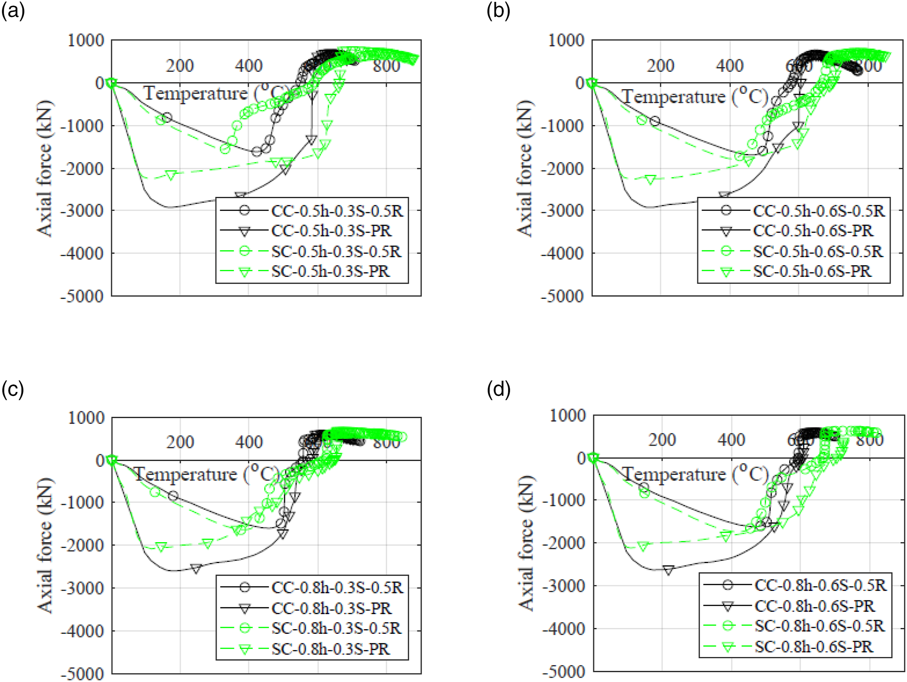
Despite the higher thermal expansion of stainless steel, the stainless steel beams exhibit lower thermal-induced peak compressive forces than the carbon steel beams as shown in Figure 12. For the beams with pin–pin end supports, the peak compressive force in the carbon steel beam was approximately 26% higher than that for the stainless steel beam. This is due to the different rate of degradation of the mechanical properties, in particular the yield strength, of the two materials with temperatures as is shown in Figure 13. The higher reduction in the yield strength of stainless steel over the temperature range of 20–600°C (for EN 1.4301) resulted the beams to develop into the plastic phase of the material which restricted the increase of the peak compressive force – similar observations were also made in Pournaghshband et al. (2019) for the case of restrained solid stainless steel beams. It can, therefore, be deduced that at high axial restraint levels, using stainless steel beams is advantageous as it generates lower levels of thermal-induced peak compressive force on the adjacent cold structures. Strength reduction factor of carbon and stainless steel with temperature.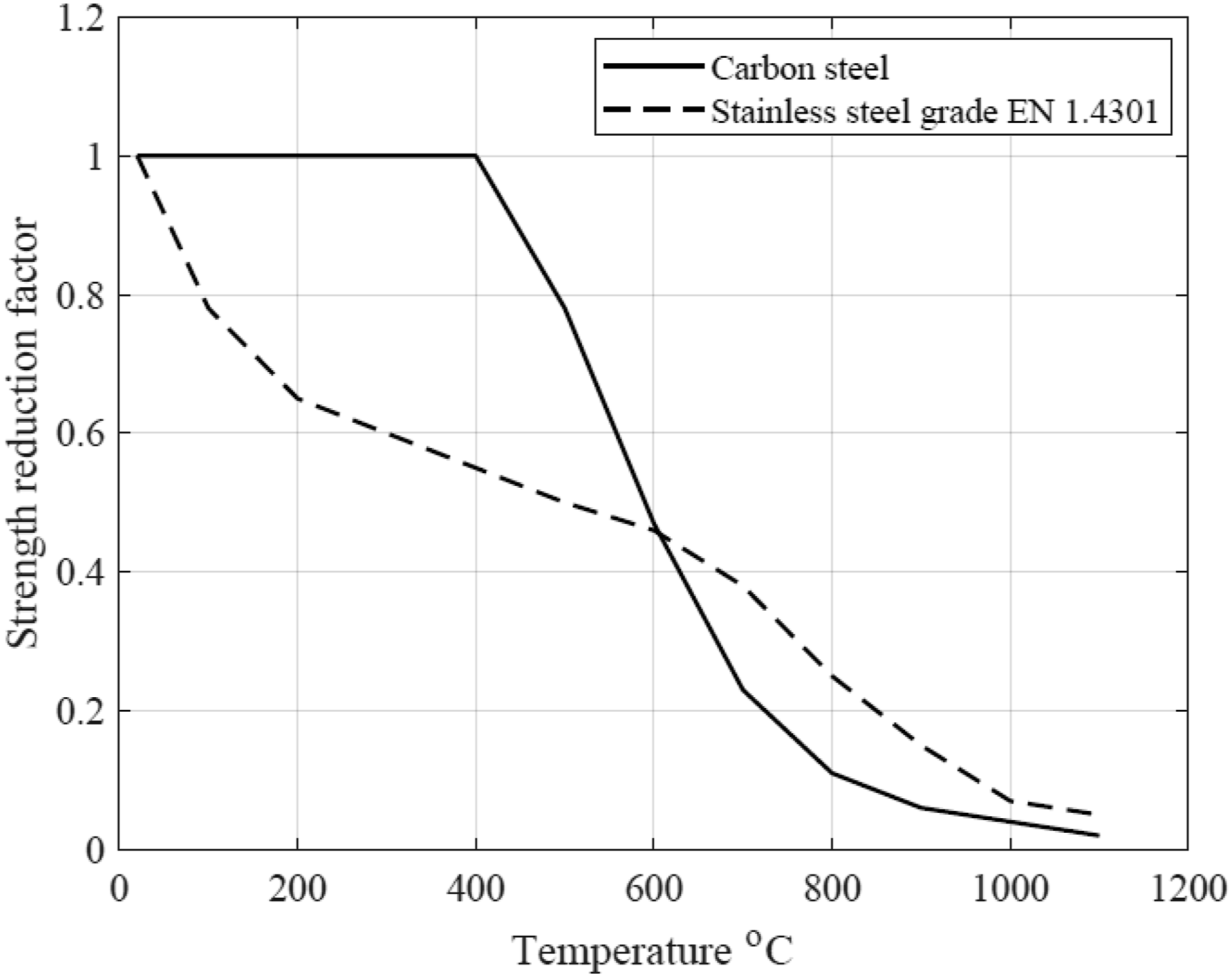
Transition and failure temperatures and effect of load ratio
The behaviour of stainless and carbon steel perforated beams were compared in terms of two temperatures – the transition temperature and the failure temperature. The transition temperature is defined as the temperature at which the thermally induced axial compressive force in the restrained beams reaches zero and the beams enter the catenary action phase. The failure temperature is defined as the temperature at which the maximum tensile force in the catenary response range is reached; this temperature reflects the survivability of the beam at high temperatures.
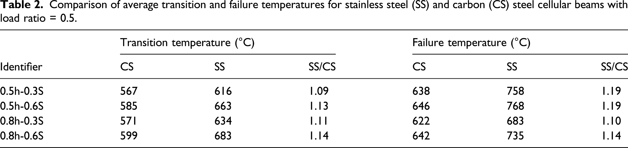
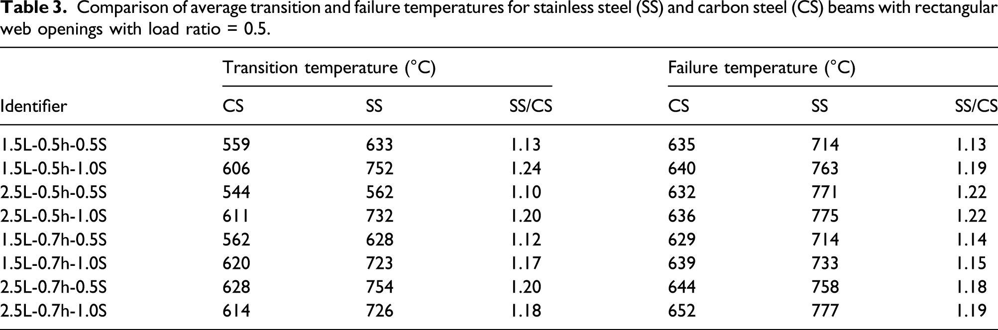
For the restrained perforated beams with the same geometric dimensions and different degrees of axial restraints, the transition and the failure temperatures were only slightly affected by the axial restraint value for both materials, as it is shown in Figures 14(a) and (b) for beams with cellular web openings and Figures 14(c) and (d) for beams with rectangular web openings. The transition and failure temperatures for each of the modelled beam geometries, averaged over the different axial restraint levels, are summarised in Table 2 for cellular openings and Table 3 for rectangular openings. It is seen that the stainless steel beams have higher transition and failure temperatures than the carbon steel beams. This is because the yield strengths of carbon and stainless steel degrade at different rates with temperature as shown in Figure 13. Within the lower temperature range (e.g. <600°C for EN 1.4301), the strength retention factor of stainless steel is lower than that of the carbon steel, however at higher temperatures (e.g. >600°C for EN 1.4301), the situation is reversed and the strength retention factor of the stainless steel becomes higher. For the stainless steel beams reported in Tables 2 and 3, the transition and failure temperatures were observed in the temperature range of >600°C, at which the strength reduction factor of the stainless steel is higher than that of the carbon steel, which explains their higher values compared to the carbon steel beams. Axial force developed in carbon steel and stainless steel beams with rectangular and circular web openings. (a) Cellular beams with carbon steel. (b) Cellular beams with stainless steel. (c) Rectangular beams with carbon steel. (d) Rectangular beams with stainless steel. Comparison of average transition and failure temperatures for stainless steel (SS) and carbon (CS) steel cellular beams with load ratio = 0.5. Comparison of average transition and failure temperatures for stainless steel (SS) and carbon steel (CS) beams with rectangular web openings with load ratio = 0.5.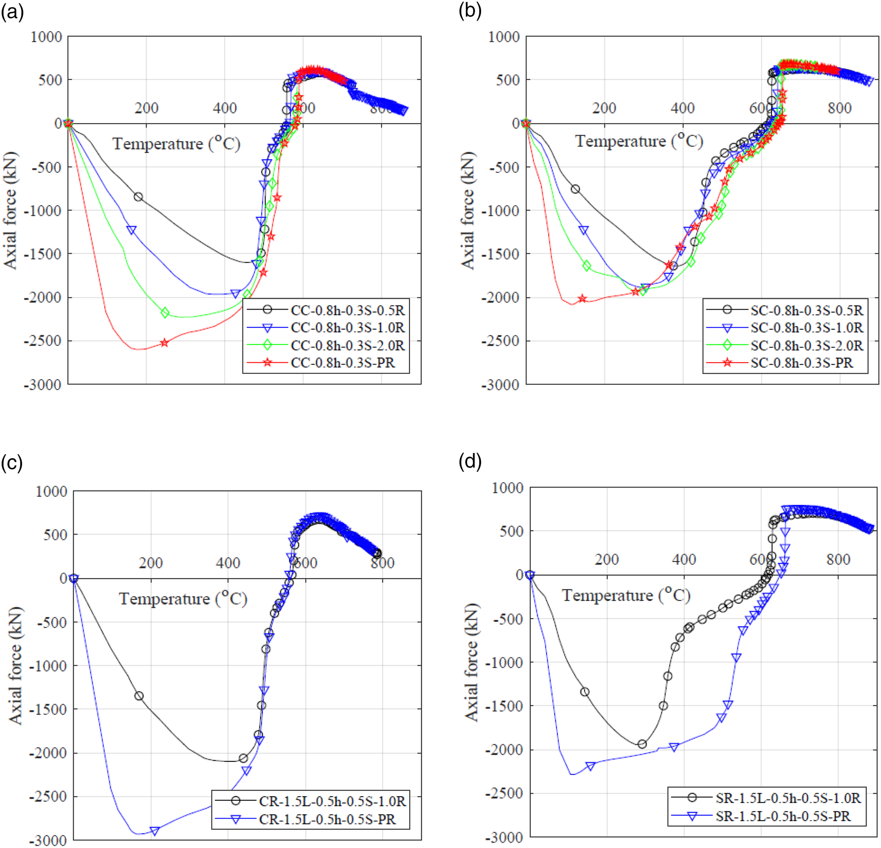
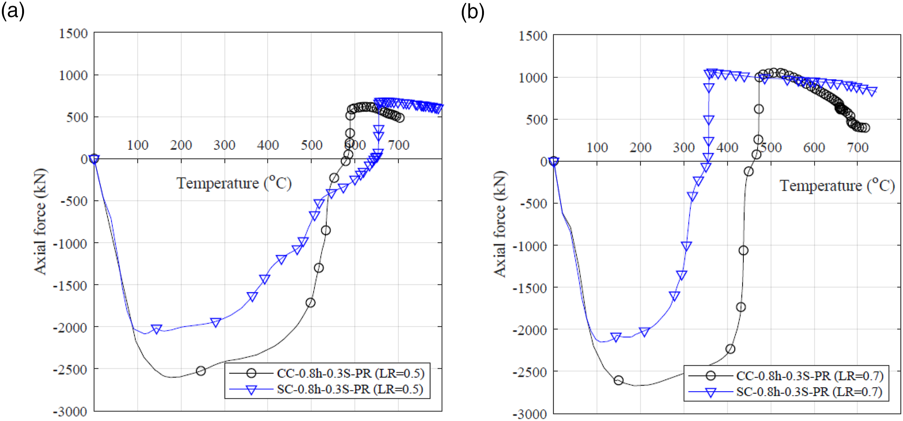
The transition and failure temperatures of stainless and carbon steel perforated beams subjected to a higher load ratio of 0.7, such that these temperature limits were reached within the lower temperature range, that is, <600°C, were also investigated. Figure 15 compares the displacement–temperature response of both unrestrained and fully restrained carbon and stainless steel cellular beams subjected to two load ratios 0.5 and 0.7. The axial force–temperature responses of fully restrained carbon and stainless steel cellular beams subjected to these two load ratios 0.5 and 0.7 are also shown in Figure 16. From these responses, it is evident that, as expected, increasing the load ratio to 0.7 results the transition and failure temperatures of the carbon steel beams to be higher than those of the stainless steel beams. Displacement-temperature curves for cellular carbon and stainless steel beams with load ratio = 0.5 and 0.7. (a) Unrestrained beam with load ratio = 0.5. (b) Restrained beam with load ratio = 0.5. (c) Unrestrained beam with load ratio = 0.7. (d) Restrained beam with load ratio = 0.7. Axial force-temperature curves for cellular carbon and stainless steel beams with load ratio = 0.5 and 0.7. (a) Restrained beam with load ratio = 0.5. (b) Restrained beam with load ratio = 0.7.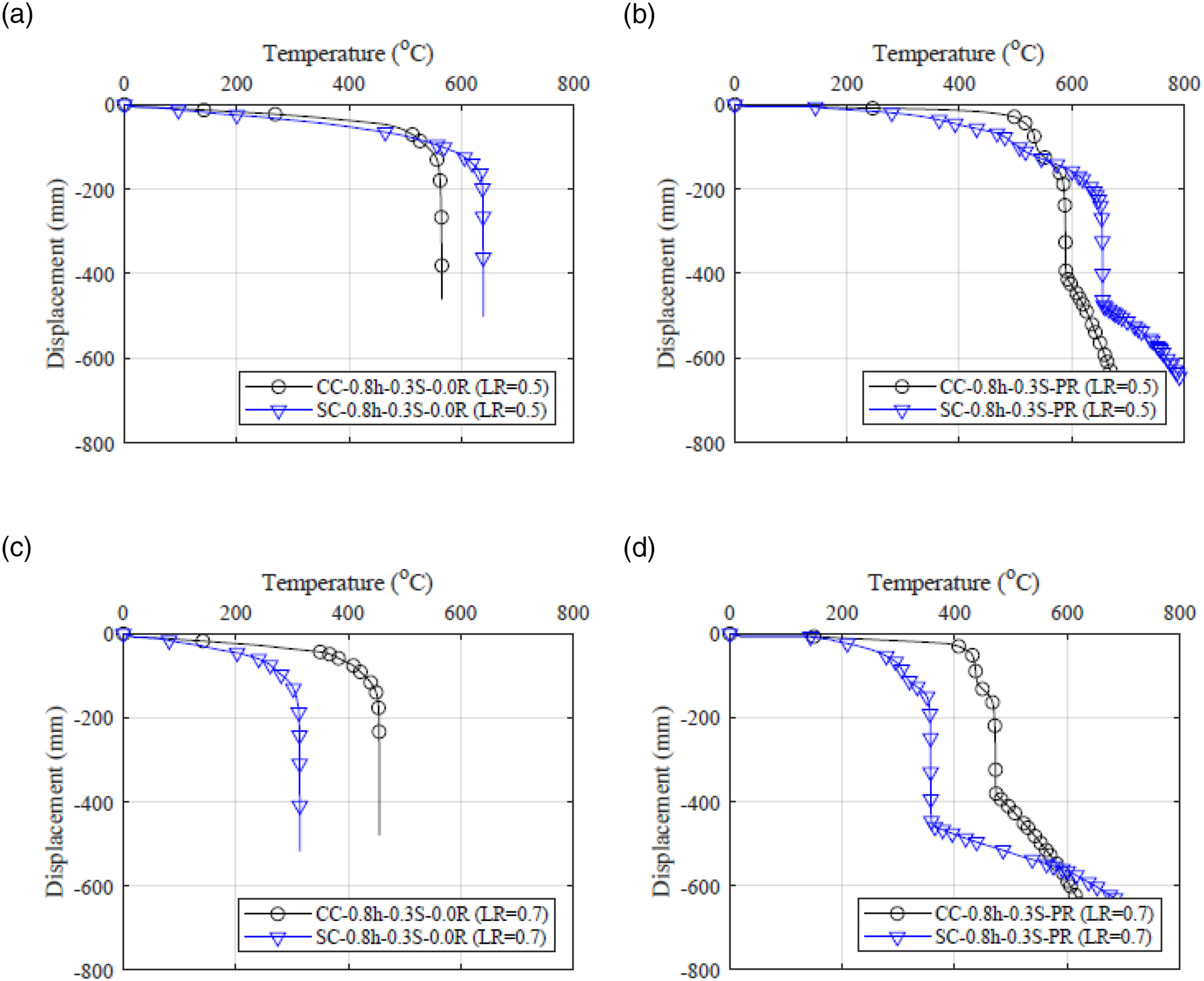
Comparisons with the SCI calculation method
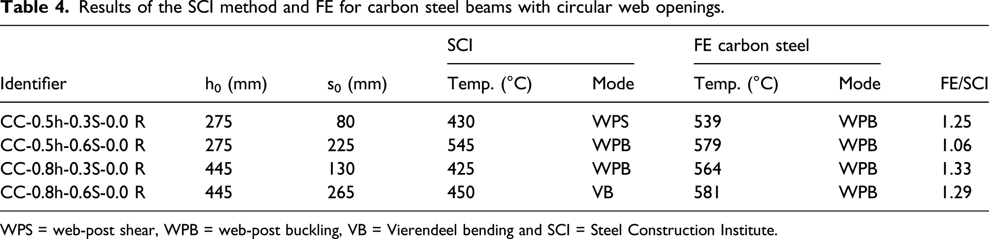
Figure 17 summarises the main failure modes of perforated steel beams in fire and their associated design equations as specified in the SCI publication RT1365 (SCI RT1365, 2013). The failure mode and the corresponding limiting temperature of the modelled perforated beams were predicted based on the SCI method (SCI RT1365, 2013). Uneven temperature distribution across the beam section, similar to those used in the FE models, was considered during the calculations. Several trials were carried out, where the temperature was increased while the load ratio was set at 0.5, until failure was observed in one of the main failure modes. Table 4 reports the failure mode and the corresponding limiting temperature from both FE and the SCI method (SCI RT1365, 2013) for the modelled carbon steel cellular beams. It should be noted that since the SCI method is for the design of unrestrained beams, the unrestrained models were considered in the comparisons only. The limiting temperatures observed by the FE analysis, corresponding to the web-post buckling failure, were higher than those predicted by the SCI method by 6% and 33%. The under prediction by the SCI method is due to the fact that the failure loads predicted by the SCI method are based on the first stage of material yielding or buckling of the critical web-post, and do not take into account the redistribution of the loads to the less stressed parts of the beam which occurs in the FE models. Summary of the Steel Construction Institute [8] design method. Results of the SCI method and FE for carbon steel beams with circular web openings. WPS = web-post shear, WPB = web-post buckling, VB = Vierendeel bending and SCI = Steel Construction Institute.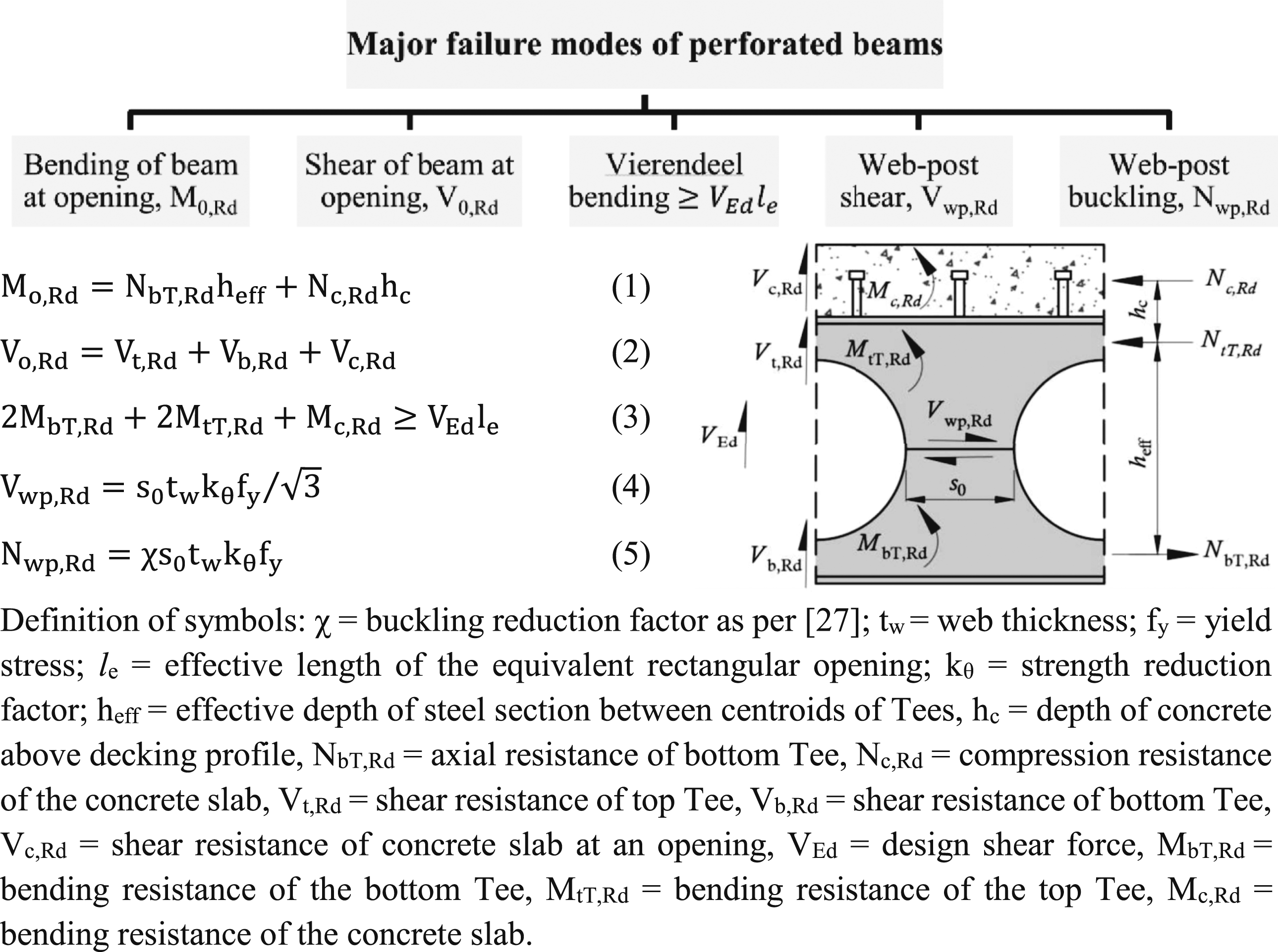
Results of the SCI method and FE for stainless steel beams with circular web openings.
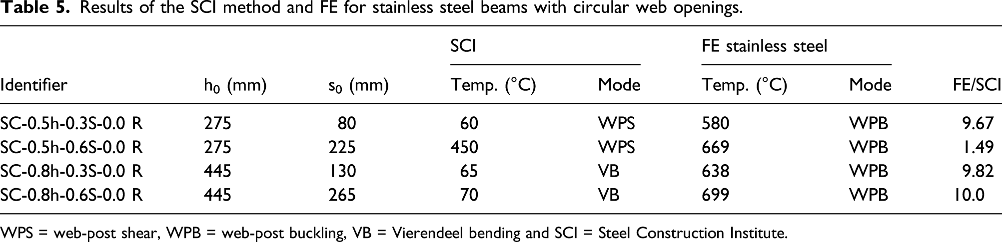
WPS = web-post shear, WPB = web-post buckling, VB = Vierendeel bending and SCI = Steel Construction Institute.
Conclusions
The fire performance of carbon and stainless steel (EN 1.4301) composite beams with circular and rectangular web openings were investigated numerically in this article. An extensive parametric study, using FE models that were validated against experimental tests found in the literature, was carried out. The beams were analysed under various levels of load ratio and axial restraint covering the ranges which may exist in practice. Furthermore, the applicability and accuracy of the SCI method for the design of perforated beams were assessed. The stainless steel perforated beams showed a more ductile fire response than carbon steel beams of similar geometry. The ductility of the stainless steel allows load distribution between the web-posts to take place, hence providing a stable response compared with the carbon steel beams. Furthermore, the limited ductility of carbon steel beams, together with significant loss of strength at high temperatures 600–800°C, makes them more likely to fail by tensile rupture within the catenary phase, particularly with large web opening areas. Furthermore, the relative survivability of the stainless steel and carbon steel beams at elevated temperature was shown to depend largely on the load ratio. Stainless steel beams sustain a higher failure temperature for load ratios lower than 0.7, where failure occurs at temperatures higher than 600 °C. When a high load ratio is adopted, the situation is reserved and the carbon steel beams exhibit higher failure temperature. The SCI design method was shown to provide conservative estimation for the limiting temperature of carbon steel beams. For the stainless steel beams, the SCI method predicted inaccurate failure modes and limiting temperatures. Hence, it was proposed that the superior performance of the stainless steel beams cannot be predicted without modifying the SCI method to consider virtue of the material ductility, which tends to delay the beam failure to higher temperatures. Furthermore, buckling of T-section due to the thermal-induced compressive forces and sidesways web buckling failure modes which were observed in the FE models herein are not included in the SCI design methods.
Footnotes
Declaration of conflicting interests
The author(s) declared no potential conflicts of interest with respect to the research, authorship, and/or publication of this article.
Funding
The author(s) received no financial support for the research, authorship, and/or publication of this article.