
Abstract
As a pilot research for an aimed beam-column joint of steel prefabricated prefinished volumetric construction (PPVC) buildings, this study investigates the axial static bearing capacity of grouted square hollow section (SHS) sleeve connections via carrying out experimental tests. Ten specimens with different dimensions were tested to failure under monotonic axial compressive loading and their loading-displacement curves were measured and recorded. The effect of the grouted length, the shear-key spacing, and the grout strength to the bearing capacity of the grouted SHS sleeve connections are investigated in this study. It is found that the axial static bearing capacity of the specimens tested increases approximately in a linear manner with the grouted length increases and can reach the bearing capacity of the outer tube’s cross-section when the grouted length is sufficient. Besides, the benefits brought by the increment of the grout strength to the axial bearing capacity of the grouted SHS sleeve connection may depend on other parameters such as the shear-key size and spacing, the gap between two tubes, and the thickness of the outer tube. Therefore, more experimental tests are required to understand the effect of the grout strength comprehensively.
Keywords
Introduction
Prefabricated assembled buildings are becoming more and more popular in China. Chinese government has issued many policies to promote prefabricated assembled buildings’ applications to improve construction productivity, save the skilled laborers on-site, and reduce pollution to the environment. Among all types of assembled buildings, prefabricated prefinished volumetric construction (PPVC) has the highest assembly rate because all the modules are completed with internal finishes, fixtures, and fittings in an off-site fabrication factory before they are delivered and installed on-site.
For all PPVC buildings, beam-column joint for connecting different modules is one of the main concerns. This study mainly focuses on designing a new joint design for steel PPVC buildings. In the last decades, researchers have proposed many joints for steel PPVC buildings and conducted relevant research. Lacey et al. (2018), Liew et al. (2019), and Deng et al. (2020) have summarized and reported many typical joints used in steel PPVC buildings. Generally, bolted joints are frequently used in steel PPVC. For instance, Lawson et al. (2014) proposed a bolted joint, in which the column and the beam are rectangular hollow section (RHS) and channel section, respectively; Park et al. (2016) reported a full bolted joint, in which a cross-shaped plate is placed at the interface between the RHS columns and then bolted to the web of the channel beam, however, the upper and the below RHS columns are not connected directly; Deng et al. (2017) proposed a modified bolted joint based on the one reported by Park et al. (2016). The modified joint consists of four socket-shaped tenons welded together by a cruciform gusset plate, which is bolted both to the web and the flange of the channel beams; Later, Deng et al. (2018a, 2018b) proposed another bolted joint with a welded cover plate and investigated its seismic behavior under both cyclic and monotonic loadings; Chen et al. (2017a, 2017b) proposed a joint in which both the column and the beam are rectangular hollow sections. The upper and the below RHS columns are connected by an internal sleeve, and the ceiling and the floor beams are joined by three long bolts. Besides, adjacent modules at the same level are bound by a gusset plate welded to the internal sleeves; Wang et al. (2019) proposed a bolted joint with the upper and the below modules connected through a bolt installed inside the columns.
In addition to the bolted joints mentioned above, researchers have also proposed and investigated some beam-column joints for steel PPVC buildings involving post-tensioned threaded rods and plug-in self-lock devices. For instance, Sanches et al. (2018) proposed a joint using a post-tensioned threaded rod to connect the upper and the below RHS columns of two modules; Chen et al. (2017c) reported a similar joint in which the pre-stressed strands instead of the post-tensioned threaded rod are used to connect the upper and the below RHS columns of two modules; Dai et al. (2019) proposed a plug-in self-lock joint for steel PPVC buildings and investigated its seismic performance under cyclic loading; Chen et al. (2019) also designed a plug-in connector for inter-module connection in mid-rise steel PPVC buildings and investigated its rotational stiffness by carrying out both experimental tests and finite element analyses (FEA). For the joints using the post-tensioned threaded rods or the self-lock plug-in connectors, the rotational stiffness is generally weak because only the rods or the connectors provide the vertical continuity (Liew et al., 2019).
The rotational stiffness of the beam-column joints for steel PPVC buildings is crucial for resisting lateral loadings caused by the seismic action and the wind loading (Deng et al., 2020; Liew et al., 2019). A bolted beam-column joint may be treated as rigid (Lee et al., 2017b), semi-rigid (Chen et al., 2017a; Li et al., 2017), or pinned joint (Annan et al., 2009; Lawson et al., 2014) according to its unique configuration. If a bolted joint is a pinned connection, designers have to increase the cross-section size or the thickness of each module’s columns, and thus material cost will be increased accordingly (Liew et al., 2019). Besides, the contribution of the joint to the lateral resistance of the entire building will be low because of its weak rotational stiffness. To increase the rotational stiffness of the bolted joints for steel PPVC buildings, generally it is necessary to connect the floor and the ceiling beams using long bolts and weld a diagonal stiffener at each corner of the joint. However, large amounts of bolts may cause difficulties in bolting and hence propose very stringent fabrication tolerance (Liew et al., 2019). Besides, the welded stiffener may also make the beam and the column vulnerable to fracture at the welding positions under cyclic lateral loadings. In addition, the welded stiffener may cause inconvenience to the wall construction because it occupies the wall-corner’s space.
The authors aim to design a rigid beam-column joint for steel PPVC buildings by modifying the one shown in Figure 1(a). For the aimed joint, which is shown in Figure 1(b), there is no long bolts and stiffener shown in Figure 1(a); the upper and the below square hollow section (SHS) columns are connected via the grout filled in-between of the internal sleeve and the SHS columns. To achieve high rotational stiffness, Shear-key has to be fabricated at the sleeve’s outer surface and the SHS columns’ inner surface, as shown in Figure 1(b). Grouted circular hollow section (CHS) sleeve connection shown in Figure 2(a) has been widely used in offshore structures (Dallyn et al., 2015; Krahl and Karsan, 1985; Lee et al., 2017a). For the shear-key design of grouted CHS sleeve connections, several guidelines are available such as DNVGL-ST-0126 (2018) and API-RP-2A-WSD (2005). However, to the authors’ knowledge, there is no such guideline for the grouted SHS sleeve connection shown in Figure 2(b). Recently, Dai et al. (2020) reported a very detailed study on the axial load resistance of 15 grouted SHS sleeve connections. In order to design the proposed grouted beam-column joint for steel PPVC buildings, it has firstly to determine the shear-key parameters, including the size and spacing of the shear-key and the grouted length. Dai et al. (2020) have also carried out a similar investigation, yet they have not investigated the effect of the grouted length to the axial static bearing capacity of the grouted SHS sleeve connection. In this study, the authors investigated the axial static bearing capacity of the grouted SHS sleeve connection and the effect of the grout strength, the shear-key spacing, and the grouted length. This study is a pilot research for designing the grouted beam-column joint used in steel PPVC buildings.
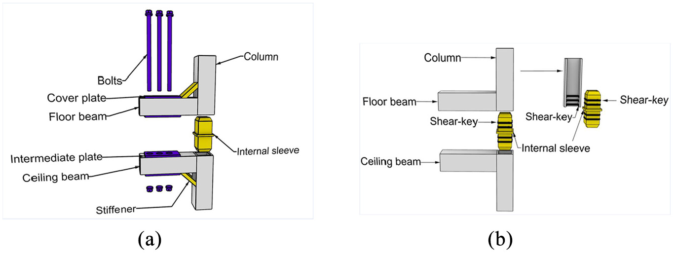
Beam-column joints for steel PPVC buildings: (a) joint proposed by Chen et al. (2017a, 2017b) and (b) joint proposed in this study.
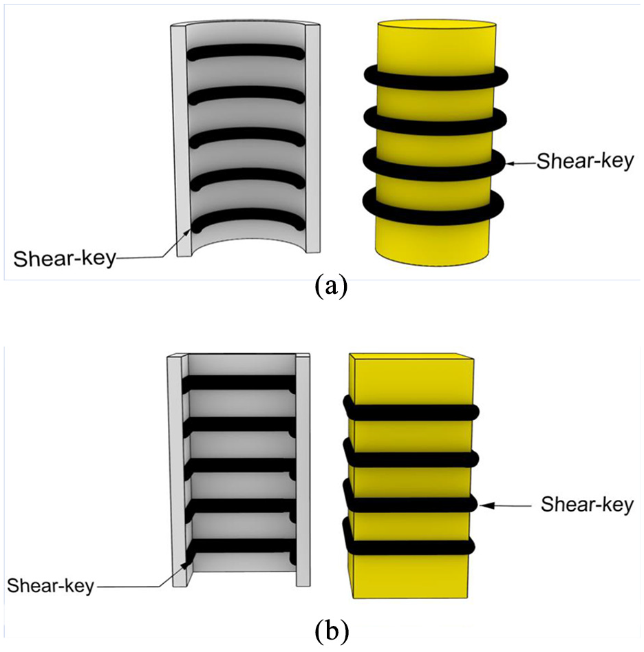
Grouted sleeve connections: (a) CHS tubes and(b) SHS tubes.
Design and fabrication of specimens
Figure 3 shows the sectional view of the grouted SHS connection. Parameter Ds is the width of the outside SHS tube, and parameter Dp is the width of the inside SHS tube. Parameter l1 is the grouted length between two SHS tubes with the same length l. The shear-key shown in Figure 3, which is the weld bead in this study, is crucial for the grouted SHS sleeve connection to achieve sufficient strength. As there is no specific guideline to design the grouted SHS connections to date, the authors refer to the API-RP-2A-WSD (2005) approach which is for designing the grouted CHS sleeve connections using the same weld bead as the shear-key.
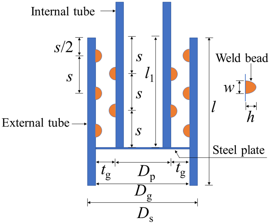
Parameters of a grouted SHS or CHS sleeve connection.
According to the API-RP-2A-WSD (2005) code, the gap between the outer and the internal CHS tg, height of the weld bead h, width of the weld bead w, and distance between two weld beads s are critical parameters, and they should meet the requirements below:
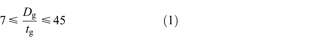
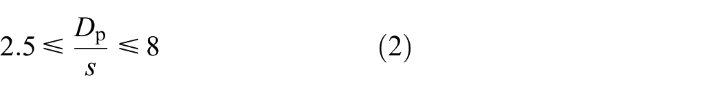
For the grouted SHS sleeve connections investigated in this study, the section dimensions of the outside and inside SHS tubes are 150 mm × 150 mm × 7.5 mm and 100 mm × 100 mm × 7.5 mm, respectively. Let the circumferential length of the SHS tube equals a CHS one, the equivalent diameter of the two SHS tubes are 191 mm (Dg) and 172 mm (Dp), respectively. By substituting values of Dg and Dp into equations (1) and (2) respectively, range of parameters tg and s should satisfy equations below:


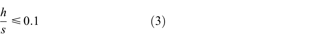
Further, by substituting values of s into Eq. (3), we may estimate the range of h as follows:

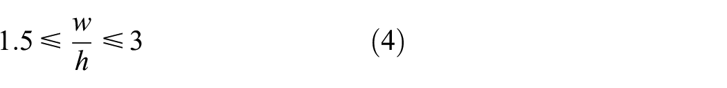
Further, by substituting values of h into Eq. (4), we may estimate the range of w as follows:

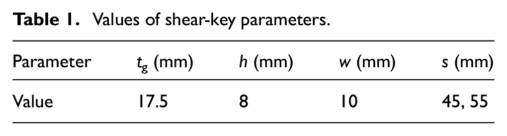
For the grouted SHS sleeve connection specimens, values of tg, h, w, and s are listed in Table 1. Value of tg is within the calculated ranges above. Value of h is increased to 8 mm for all grouted SHS connection specimens because it is difficult to fabricate the weld bead which the height is less than 5.1 mm. As a result, equation (4) is no longer satisfied. Two values of s are adopted for the specimens, and the value of 55 mm is slightly larger than the maximum given in equation (6).
Values of shear-key parameters.
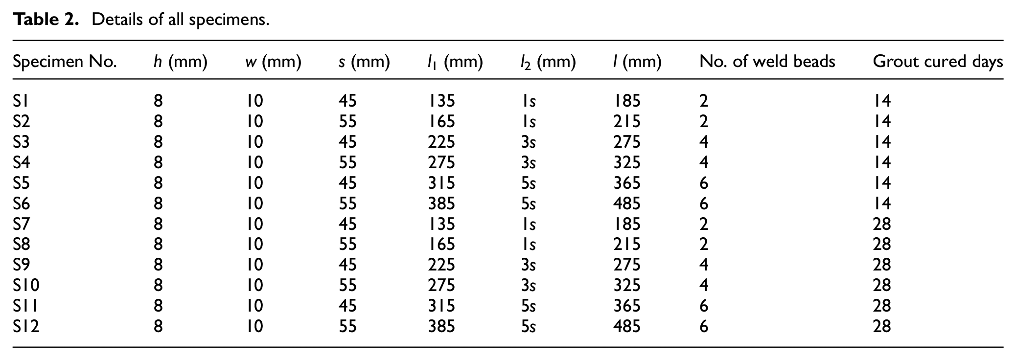
As shown in Table 2, 12 grouted SHS sleeve connections have been fabricated. The SHS tube is of Q235 cold formed steel. The number of weld beads in Table 2 refers to those on the external surface of the inside SHS tube. Specimens S6 and S12 have not been tested on time as scheduled due to the coronavirus outbreak in Wuhan, China.
Details of all specimens.
Material properties of the steel and the grout
The steel
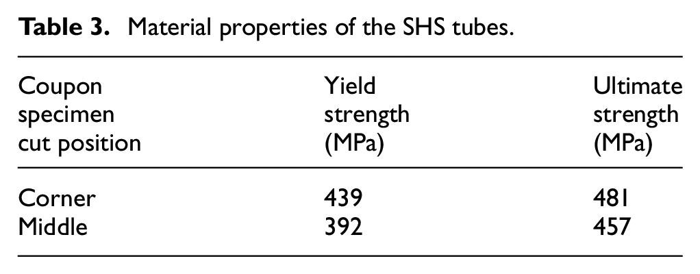
Coupon test specimens shown in Figure 4 were fabricated by cutting from the outside SHS tubes. In order to consider the material strength hardening at the corners of the SHS tube, coupon specimens were also cut from the position near one corner as shown in Figure 5. The material properties, including the yield strength and ultimate strength of the outside SHS tube, are summarized in Table 3. Full engineering stress-strain curves are shown in Figure 6. The steel strength is a bit higher at the corner of the SHS tube.
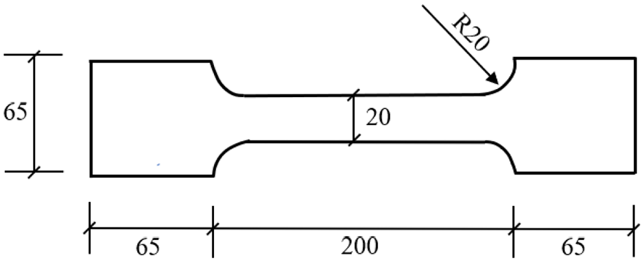
Dimensions of the coupon test specimens.
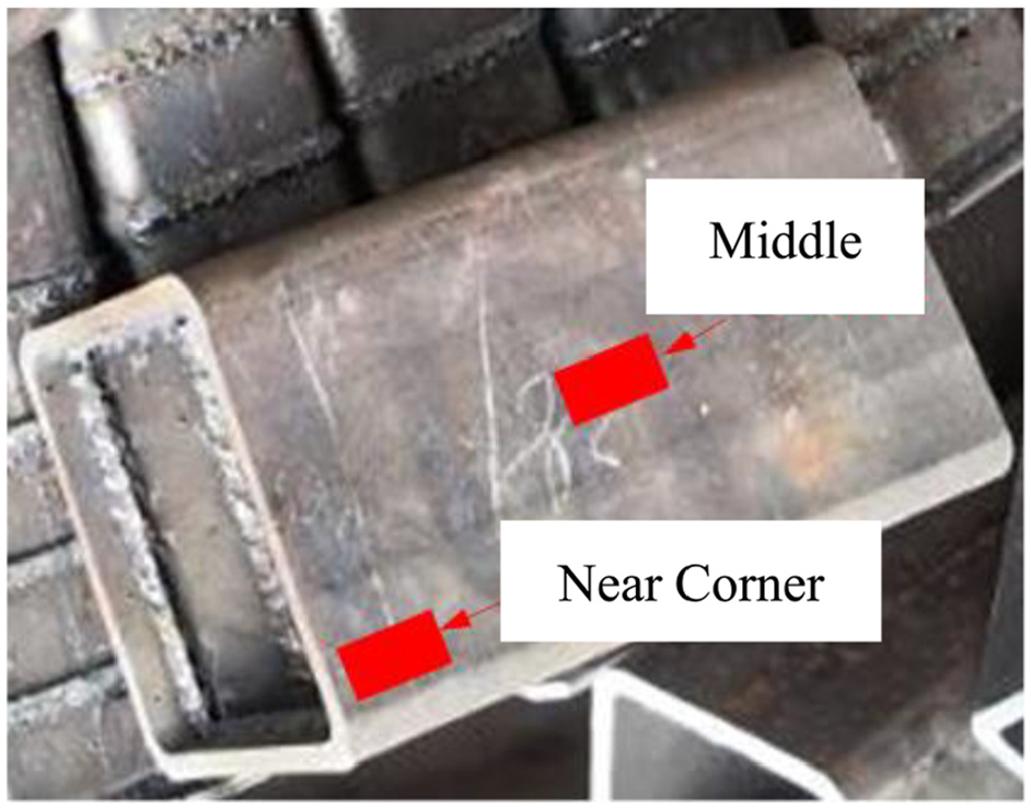
Two cutting positions of the coupon specimens.
Material properties of the SHS tubes.
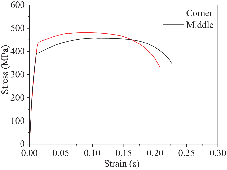
Engineering stress-strain curves of the SHS tube.
The grout
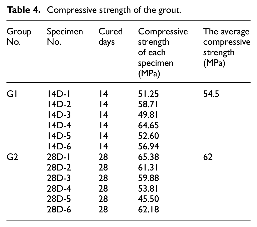
The specimens for testing the compressive strength of the grout are fabricated and tested following the Chinese standard JG/T408-2013 (2013). The dimensions of the specimen are 40 mm × 40 mm × 160 mm. The specimens were prepared in the molds shown in Figure 7 for 24 h, and then all of them were put in a water tanker for further cure out of the door after removing the mold. A total of 12 specimens were fabricated and divided into two groups, and they were kept immersing in water until the compressive strength testing. Figure 8 shows the set-up for testing the compressive strength of the grout. The compressive strength of the grout is taken as the average of six specimens in each group. If a strength value is 10% diverged from the average of the six specimens, it needs to be omitted, and the compressive strength of the grout is then taken as the average of the remaining five specimens. The compressive strength of the grout cured for 14 and 28 days are 54.47 and 61.95 MPa, respectively. The compressive strength of 12 specimens is summarized in Table 4.
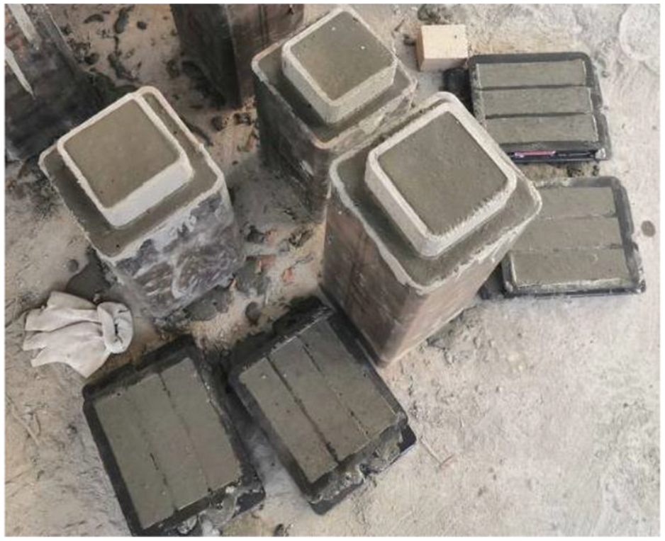
Standard specimens for testing the compressive strength of the grout.
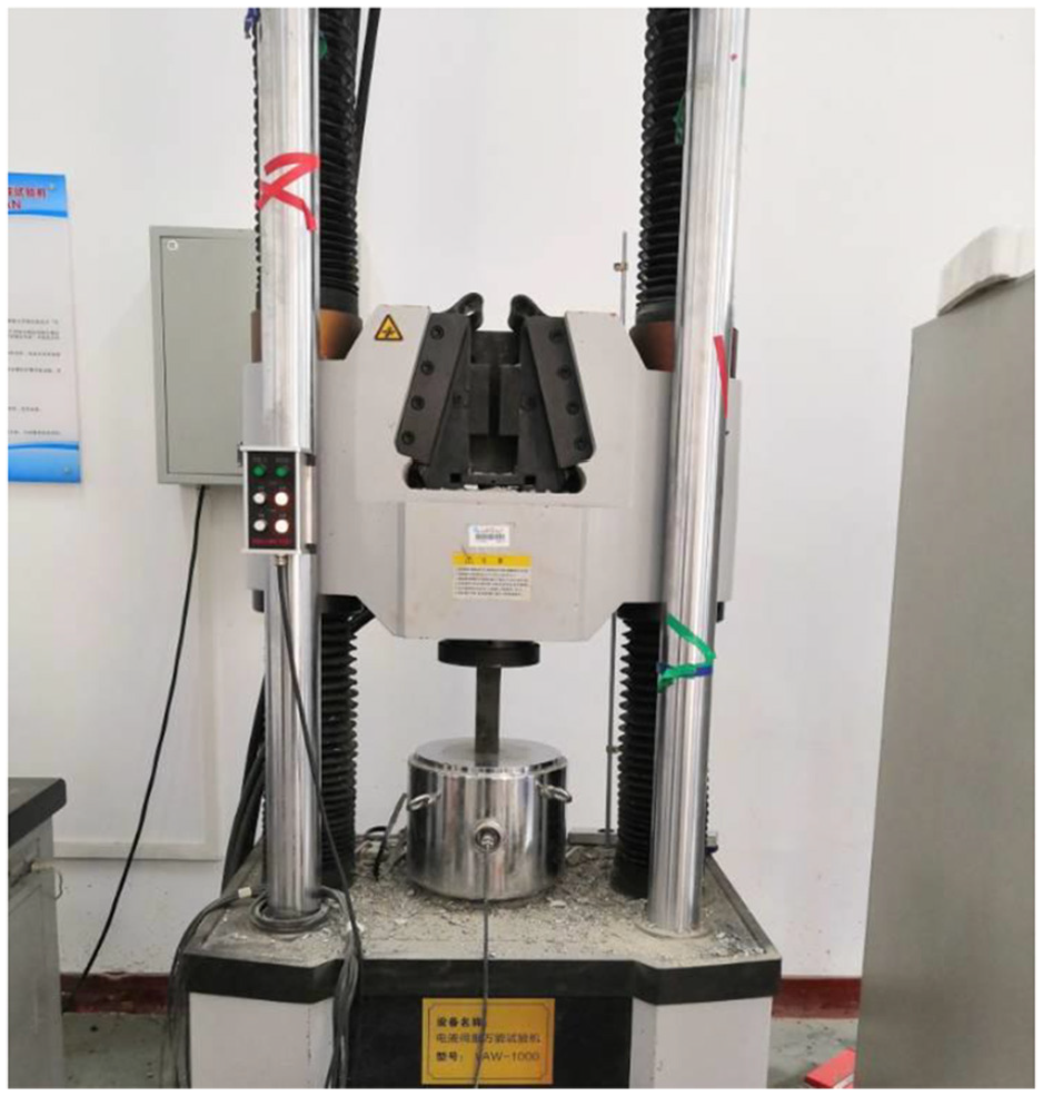
Set-up for testing the compressive strength of the grout.
Compressive strength of the grout.
Experimental tests
Test rig
All the grouted specimens were tested to failure under axial compressive load. As shown in Figure 9, the specimen is placed on a loading cell, and a displacement transducer is used to measure the vertical displacement of the inside tube. For each specimen, a preload of 100 kN is applied to check the work performance of the loading and data collecting systems, and then axial compressive loading is applied using displacement control mode at a speed of 0.01 mm/s.
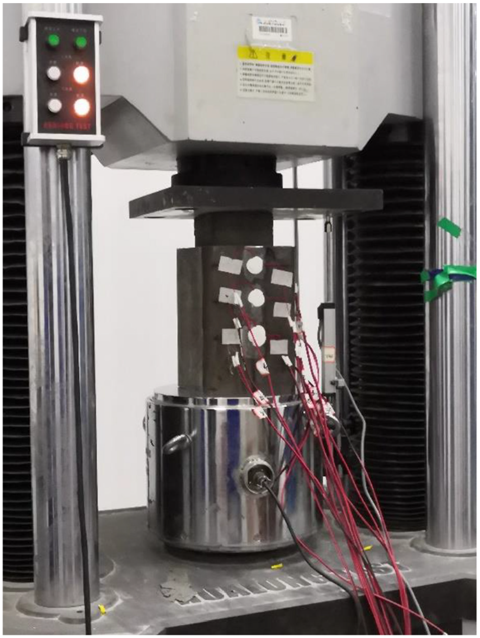
Set-up of the grouted SHS sleeve connection subjected to axial compressive loading.
Failure modes of the grouted SHS sleeve connections
Two typical failure modes have been observed and shown in Figure 10(a) and (b), respectively. For the specimen S1, S2, S3, S7, S8, and S10, the internal sleeve is compressed into the outer tube and the grout is failed; however, the two SHS tubes are intact. For the specimen S4, S5, S9, and S11, the external SHS tube is fractured at one corner. Meanwhile, the grout at the corner is crushed to failure. The second failure mode, that is, fracture of the external tube has not been reported by Dai et al. (2020), it is most probably because their specimens are fabricated using grade S355 instead of Q235 structural steel.
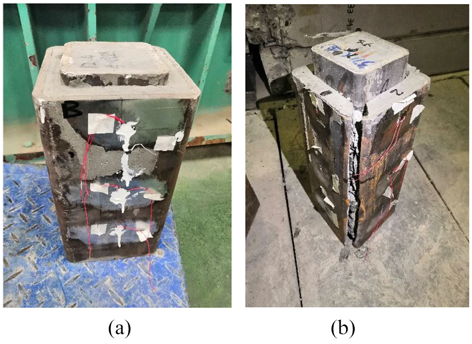
Typical failure modes of the grouted SHS sleeve connections: (a) the grout failure (S3) and (b) the outer tube fracture (S11).
Axial ultimate bearing capacity of the grouted SHS sleeve connections
Figure 11(a)–(d) show the loading-displacement curves of 10 specimens. Displacement of some curves such as S4 and S5 are shorter because the external SHS tube fractured at the corner during loading, and the axial loading decreases quickly after the peak is reached. For those specimens which the internal sleeve is compressed into the outer tube such as S1, S2, S3, and S10, loading decreases gradually to a small value after the peak is reached. The remaining small resistance maybe due to the friction between the weld bead and the grout.
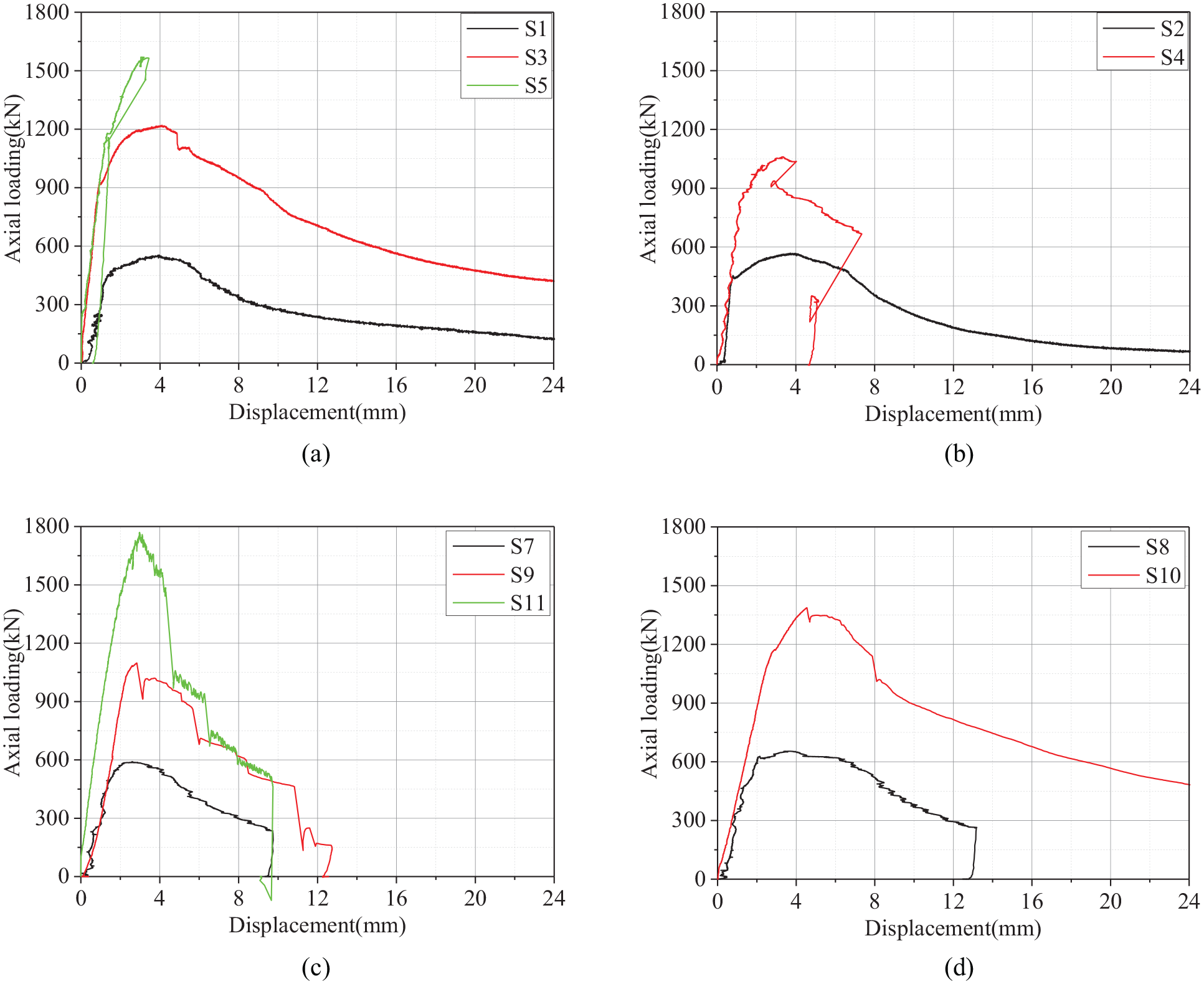
Loading-displacement curves: (a) S1, S3, and S5, (b) S2 and S4, (c) S7, S9, and S11, and (d) S8 and S10.
Figure 12 shows the axial ultimate bearing capacity of 10 specimens. The axial ultimate bearing capacity of each specimen is defined as the peak value of the corresponding loading-displacement curve shown in Figure 11(a)–(d). It can be seen that the axial ultimate bearing capacity of the grouted SHS sleeve connection increases with increasing the grouted length. By multiplying the yield strength (the average of 439 and 392 MPa) and the cross-section area (≈4275 mm2), the axial ultimate axial bearing capacity of the external SHS tube’s cross-section can be estimated, and it is about 1776.3 kN. Only specimen S11 has nearly the same axial bearing capacity as the outer SHS tube’s cross-section.
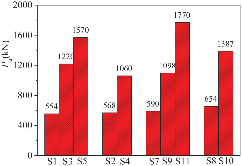
Axial ultimate bearing capacity of 10 specimens.
Effect of the grouted length
A strength enhancement factor is used to qualify the effect of the grouted length, and it is the ratio of the ultimate bearing capacity of two specimens with different grouted length herein. In this section, the grouted length is taken as the effective part instead of the physically grouted length. As shown in Figure 13, axial loading is applied to the inner tube, and then transferred to the outer tube through the grout and the weld bead. The grout will be crushed to form structs under compression. These structs will provide the main resistance to the shear loading transferred between the two tubes. Therefore, the effective grouted length, which is l2 shown in Figure 13, is defined as the part containing the structs at the inner tube side for the specimens in this study. The effective grouted length l2 of each specimen can be found in Table 2. For instance, the effective grouted length of specimen S3 is three times of S1, and the corresponding strength enhancement factor is equal to 2.2, which is the axial ultimate bearing capacity of specimen S3 divided by S1. Figure 14 shows the strength enhancement factors when the effective grouted length is increased from 1s to 5s, where s is the spacing between two adjacent weld beads. The strength enhancement factor qualifies the efficiency of the effective grouted length. It can be seen that the axial ultimate bearing capacity of the grouted SHS sleeve connections almost linearly increase with the increment of the effective grouted length.
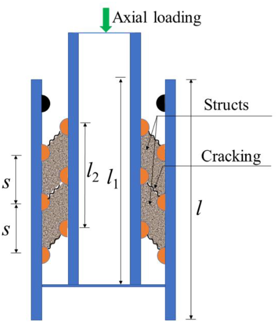
Definition of the effective grouted length l2.
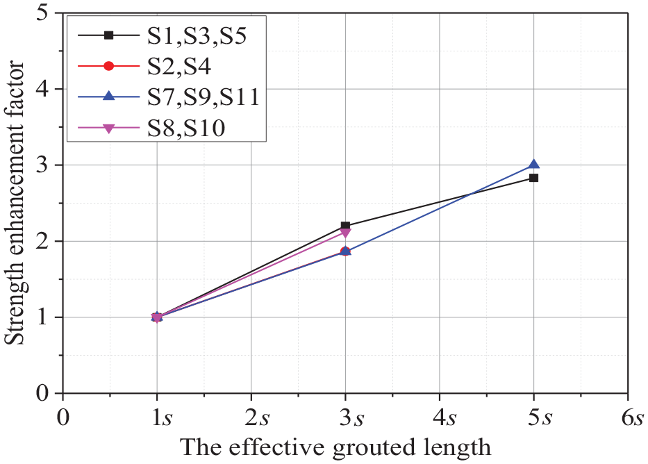
Effect of the effective grouted length to the axial ultimate bearing capacity of the grouted SHS sleeve connections.
Effect of the grout strength
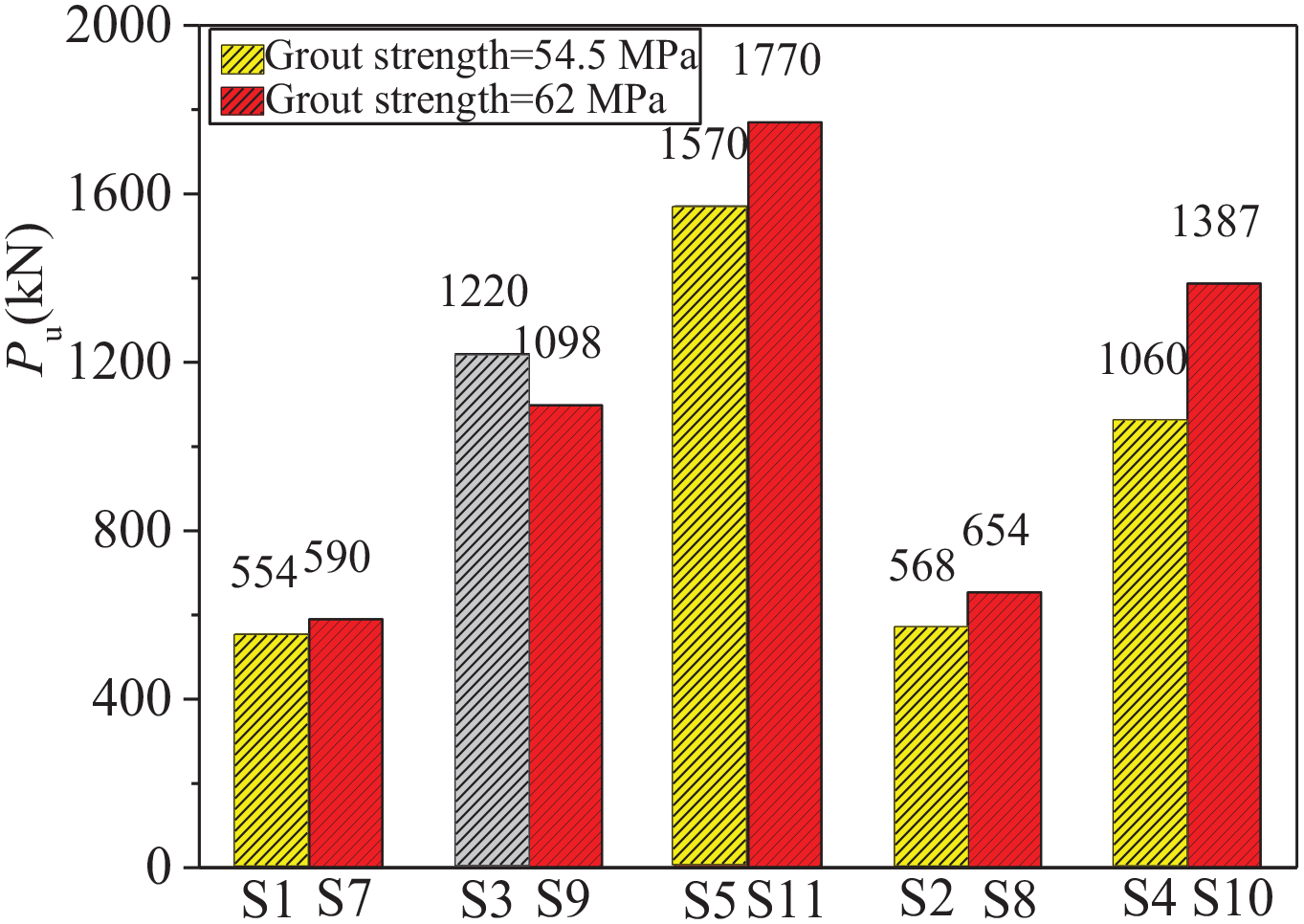
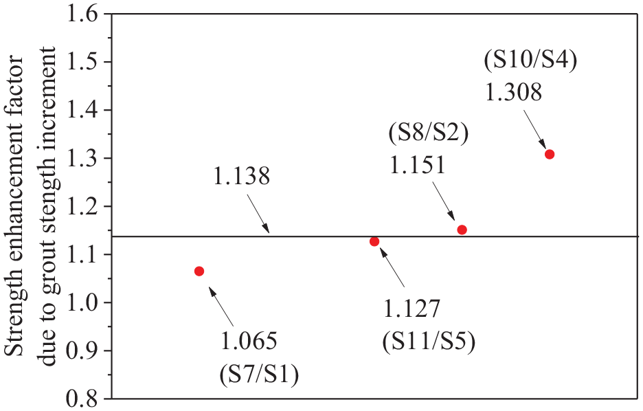
The grout’s compressive strength increases from 54.5 to 62 MPa after another 14 days of curing, with a 13.8% increment. As shown in Figure 15, the axial ultimate bearing capacity Pu of the grouted SHS sleeve connections generally increase when the grout strength increases, with the exceptions of specimens S3 and S9. Due to an incorrect operation during the loading process, the loading-displacement curve of the original specimen S3 was not obtained, and a new one was fabricated and tested subsequently. Specimen S3 shown in Figure 15 refers to the new one. The grout strength of the new specimen S3 has not been tested, and thus, the strength enhancement ratio of specimen S9 due to the grout strength increment has not been calculated. Figure 16 shows the strength enhancement ratio due to the grout strength increment for all the other specimens (omit the data point for specimen S3 and S9).
Effect of the grout strength to the axial ultimate bearing capacity of the grouted SHS sleeve connections.
Strength enhancement factor due to the grout strength increment.
For the grouted SHS sleeve connections which the grout is crushed to failure, the axial ultimate bearing capacity should increase when the grout strength increases. This is confirmed by the testing results of specimens S1 and S7, and S2 and S8. Theoretically, for the grouted SHS sleeve connections which the outer tube is fractured at the corner, increment of the axial ultimate bearing capacity should be minor when the grout strength is increased further. However, it is found that the axial ultimate bearing capacity of S11 increases by 12.7% compared to S5. Both S5 and S11 fail by steel fracture at one corner of the outer tube. Specimen S10 has a higher grout strength compared to S4. However, it is observed that the grout of specimen 10 is crushed to failure whereas the outer tube of specimen 4 is fractured. It appears that more experimental tests are required to understand the effect of the grout strength more comprehensively.
Effect of the shear-key spacing
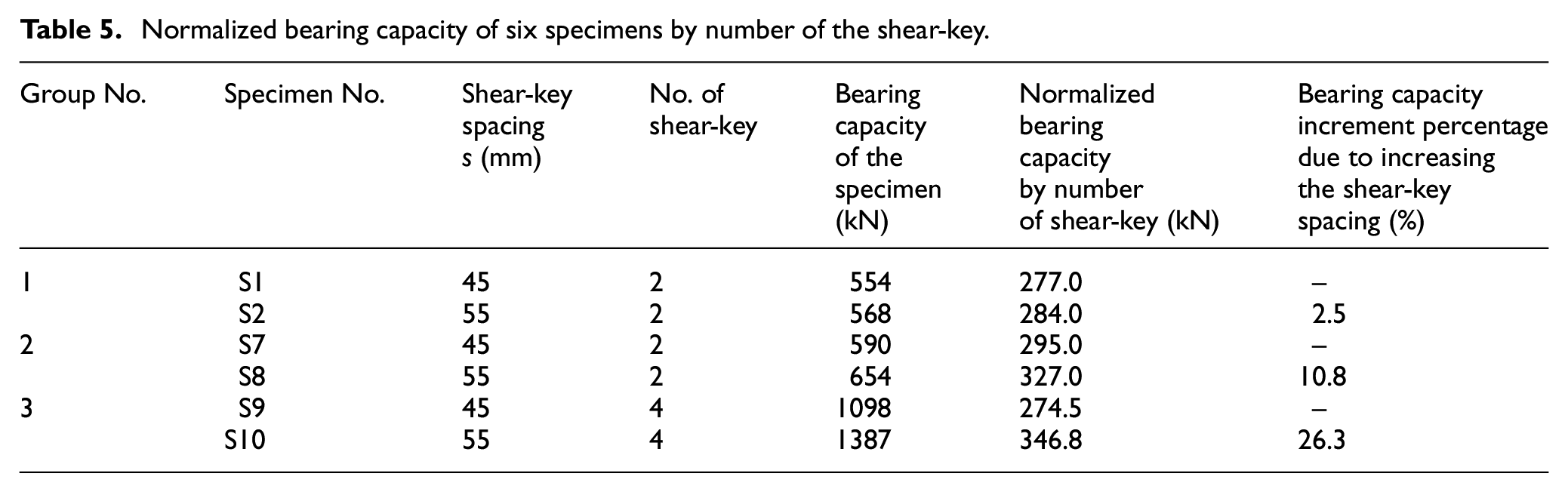
Experimental results of 6 specimens (S1, S2, S7, S8, S9, S10) are useful when investigating the effect of the shear-key spacing to the axial ultimate bearing capacity of the grouted SHS sleeve connections, and they are divided into three groups (S1 and S2; S7 and S8; S9 and S10) as shown in Table 5. According to the paper reported by Dai et al. (2020), number of shear-key will affect the number of structs under compression shown in Figure 13. Therefore, it is necessary to normalize the bearing capacity of the specimens by the number of shear-key when investigating the effect of the shear-key spacing to the axial bearing capacity of the grouted SHS sleeve connections. Table 5 shows the normalized axial bearing capacity of 6 specimens by number of the shear-key and the bearing capacity increment percentage due to increasing the shear-key spacing. It is observed that specimens with larger shear-key spacing (S2, S8, and S10) are able to bear about 2.5%–26.3% more load. Dai et al. (2020) report that grouted SHS sleeve connections with larger shear-key spacing are able to take about 15%–20% more load.
Normalized bearing capacity of six specimens by number of the shear-key.
Conclusions
The authors aim to propose a rigid beam-column joint for steel PPVC buildings without using long bolts to connect the ceiling and the floor beams, and the welded stiffener at the corner of each module’s beam-column connection. For the aimed new joint, the upper and the below SHS columns are connected via the grout filled in-between of the internal sleeve and the SHS columns. As a pilot research for the aimed new beam-column joint, this study investigates the axial static bearing capacity of grouted SHS sleeve connections subjected to axial compressive loading by carrying out experimental tests. According to the testing results, several conclusions may be drawn as follows:
Two failure modes have been observed for the grouted SHS sleeve connection specimens. For failure mode 1, the internal sleeve is compressed into the outer tube and the grout is crushed to failure; however, the outer SHS tube is intact. For failure mode 2, brittle fracture occurs at one corner of the outer tube. Meanwhile, the grout is crushed to failure at the fractured region.
The axial ultimate bearing capacity increases approximately in a linear manner with the effective grouted length increases for the specimens investigated. The axial ultimate bearing capacity of a grouted SHS sleeve connection can reach the yielding bearing capacity of the outer tube’s cross-section when the effective grouted length is sufficient.
Theoretically, the grout strength should positively affect the axial bearing capacity of the grouted SHS sleeve connections. However, the benefits brought by the increment of the grout strength may also depend on other parameters such as the shear-key size and spacing, the gap between two tubes, and the thickness of the outer tube. More experimental tests are required to understand the effect of the grout strength comprehensively.
Grouted SHS sleeve connections with larger shear-key spacing are able to bear about 2.5%–26.3% more load according to the investigation of six specimens in this study.
Footnotes
Appendix
Declaration of conflicting interests
The author(s) declared no potential conflicts of interest with respect to the research, authorship, and/or publication of this article.
Funding
The author(s) received no financial support for the research, authorship, and/or publication of this article.