
Abstract
In this study, straight composite steel-concrete beams were tested to investigate their mechanical performance under combined negative bending and torsional moments. Two specimens were used in this study, and different ratios between the applied negative bending and torsional moments were induced. Load and deflection relationships, strain development on the steel main girder and shear connectors (stud), and the slip development on the steel-concrete interface were recorded in the test and reported in this paper. The results indicate that increase of torsional moment will result in the significant decrease of the load-carrying capacities (e.g. yield load and ultimate load) of the specimens. It was also found that the normal strains of stud shear connectors in such beams are very large and non-negligible compared to their shear strains. In addition, the maximum interface slip was found occurring at around the 1/4 span, and the support conditions and serious crack of the concrete were considered to be the main causes. The research results obtained in this study can provide references for the design and analysis of steel-concrete composite beams subjected to the combined negative bending and torsional moments.
Keywords
Introduction
The steel and concrete composite section is a popular structural form and has been widely used in many civil infrastructures, like buildings and bridges, due to its efficient use of material strengths of both structural steel and concrete in simply supported beams. Compared to simply supported beams, continuous composite beams have additional advantages associated with the favorable redistribution of internal forces across the member and reduced deflection. However, the design and analysis of continuous composite beams are more complicated due to their different behavior in positive and negative moment regions (He et al., 2015; Vasdravellis et al., 2012). In straight continuous composite beams, negative bending moment regions are worthy of serious considerations due to possible concrete cracking and steel beam buckling problems. In the author’s group, a series of studies have been performed to investigate the mechanical performance of straight steel-concrete composite girders under hogging moment, including the effectiveness of static loading tests (Lin and Yoda, 2013; Lin et al., 2014b), fatigue loading tests (Lin et al., 2013), and the use of steel fibers (Lin et al., 2014a) etc. However, more severe problems could occur in steel-concrete composite beams subjected to combined negative bending and torsional moments. Structural members subjected to combined hogging bending and torsional moments are encountered in many engineering applications, such as internal support regions of curved composite bridges, or in straight bridges in which inclination and traffic loads may introduce large torsion moments on the supporting beams.
The structural behavior of steel-concrete composite beams under pure negative bending or torsion has been investigated by many researchers, such as Ko et al. (2013), Ahmed and Ahmed (2015), Zivner et al. (2016), Wang et al. (2018), Liu et al. (2019), and Liu et al. (2019). In recent years, both experimental and numerical studies have been performed to investigate the mechanical behavior of steel-concrete composite beams under combined loading. Nie et al. performed loading tests on eleven steel-concrete composite beams to study their performance under combined bending and torsional moments (Nie et al., 2009). Two failure modes, including torsion-dominated and bending-dominated failure modes, were observed. In addition, a three-dimensional behavioral truss model for analyzing composite beam sections subjected to the combined bending and torsion was presented. Tan and Uy performed a series of experimental and numerical studies on both straight and curved steel-concrete composite beams to investigate the behaviors of both straight and curved composite steel and concrete beams subjected to combined flexure and torsion (Tan and Uy, 2009a, 2009b, 2011). Particular attention was given to composite beams with partial connections. Their results support the view that, in the presence of flexure, there will be an increase in the torsional moment capacity. But the flexural moment capacity does not greatly increase in the presence of torsion. Vasdravellis et al. (2012) investigated the behavior of steel-concrete composite beams subjected to the combined effects of negative bending and axial compression by using the test results performed on six full-scale tests as well as the numerical results. It was found that, when a compressive load acts in the composite section, the negative moment capacity of a composite beam is significantly reduced and local buckling in the steel beam is more pronounced, compromising the ductility of the section. Kollar and Pluzsik (2012) presented a new theory, in which no kinematical assumption is applied in the beam theory, to predict the behavior of composite sections. Applications for open section and closed section beams are also discussed. Zhang et al. (2012) performed an experimental study to investigate the bending-torsion couple characteristics, in which six steel-concrete composite box model beams were tested under the bending-torsion couple loads. Lin and Yoda (2014c) also investigated the mechanical performance of horizontally curved steel-concrete composite beams under hogging bending moment through numerical analyses, which was the first time to investigate the interaction relation between negative bending moment and torsional moment. Kirkland and Uy (2015) investigated the structural performance of composite beams subjected to flexure and axial load, and design models are proposed for estimating the flexural strength of an axially loaded member with full and partial shear connection. Thivya et al. (2016) carried out an experimental study to investigate a newly developed composite beam called Confined Steel Concrete Composite Beam (CSCC beam) subjected to combined bending and torsion. Ban et al. (2016) investigated the strength of multi-span composite beams subjected to combined flexure and torsion, in which eight reduced scale beams under combined flexure and torsion to varying degrees are tested. Oukaili and Abdullah (2017) investigated the structural behavior of nine composite concrete-cellular steel beams under the combined effect of flexure and torsion. Also, they proposed two strengthening methods, including strengthening by intermediate stiffeners only or by both external prestressing and intermediate stiffeners.
Despite a large amount of available experimental data on composite beams under pure positive or negative bending moment, experimental data on the behavior of composite beams under combined hogging bending and torsional moments is rather limited. In addition, the current structural design codes do not provide specific rules for the design of composite beams under combined hogging bending and torsional moments; they rather refer to rules established for bare steel sections. Since the behavior of a composite beam differs substantially from that of a plain steel section, the bending moment-torsion moment interaction of composite beams deserves a particular investigation. As a result, there is a need to undertake a comprehensive study on the mechanical behaviors of composite beams subjected to combined hogging bending and torsional moments.
Experimental program
Two overturned simply supported steel-concrete composite beams with different torsion/bending ratios were tested in this study, which were similar to specimens used in previous tests on steel-concrete composite beams under a pure hogging bending moment (Lin and Yoda, 2013; Lin et al., 2014b).
Test specimen
The specimen was 4600 mm in overall length and was simply supported at a span of 4000 mm. The Design Standard for Steel-Concrete Hybrid Railway Structures (MLIT, 2009) was employed to design the test specimen. The composite beams used for this experimental study were all designed as fully (or complete) connection. The concrete slab thickness was 250 mm with a width of 800 mm. The transverse reinforcement had a nominal diameter of 13 mm and longitudinal reinforcement had a nominal diameter of 19 mm. These bars were arranged on both top and bottom of the concrete slab. The longitudinal reinforcement ratio was 2%. Thicknesses of different components of the steel main girder, including top flange, web and bottom flange of the steel main girder were 16 mm, 22 mm, and 25 mm, respectively. Besides, welded plate steel section is used in the steel girder. Initial imperfection was not observed in the steel beam after welding, and was not considered in the loading tests. The typical geometry of the test specimens is shown in Figure 1, and the test specimens before the loading tests are shown in Figure 2.
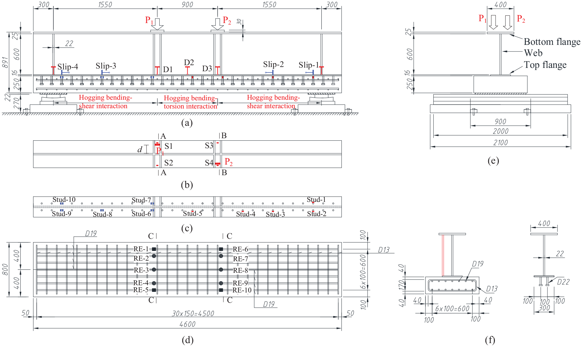
Size dimensions of test specimens: (a) side elevation, (b) bottom flange, (c) top flange, (d) deck and reinforcement, (e) sectional set-up, and (f) stiffener and stud.
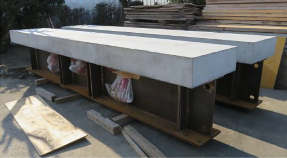
Test specimens.
The theoretical values (AASHTO, 2007) of yield and ultimate loads of the specimen considering the actual yield stress from the material tests are determined as 2112 kN and 3495 kN, respectively. Several equations were proposed to determine the ultimate torsion, such as those proposed by Singh and Mallick (1977), and Hsu (1991). The calculated ultimate torsion according to Hsu’s method is determined as 80.7 kN·m.
Test instrumentation
The beams were instrumented to measure deflections, sectional strains across the depth, applied load, and slip between the steel beam and concrete slab etc. The instrumentation set-up is shown in Figure 3. The deflections at loading points were measured using two LVDTs. The deflections at both beam ends were also recorded. Another 4 linear variable displacement transducers were employed along the longitudinal direction to measure the slip on the interface between the concrete slab and the steel beam. Strain gauges were also employed to measure the strains on the steel beam, concrete slab and reinforcing bars. Due to the difficulties in applying the torsion moment and boundary conditions, two eccentric concentrated loads were applied to create the combined torsion and negative bending moments. The beams were tested by applying two concentrated loads with roller (simple) end supports. Sectional torsion is produced by the eccentric concentrated loads. As the beams were statically indeterminate due to the torsional restraint at beam ends, Figure 4 gives the internal torsional moment diagram along the beam length. Two specimens with the same dimensions but different loading conditions were used in this study. Two test specimens are denoted as specimen-1 and specimen-2, respectively. The load eccentricity (d in Figure 1(b)) was 10 cm for specimen-1 and 15 cm for specimen-2.
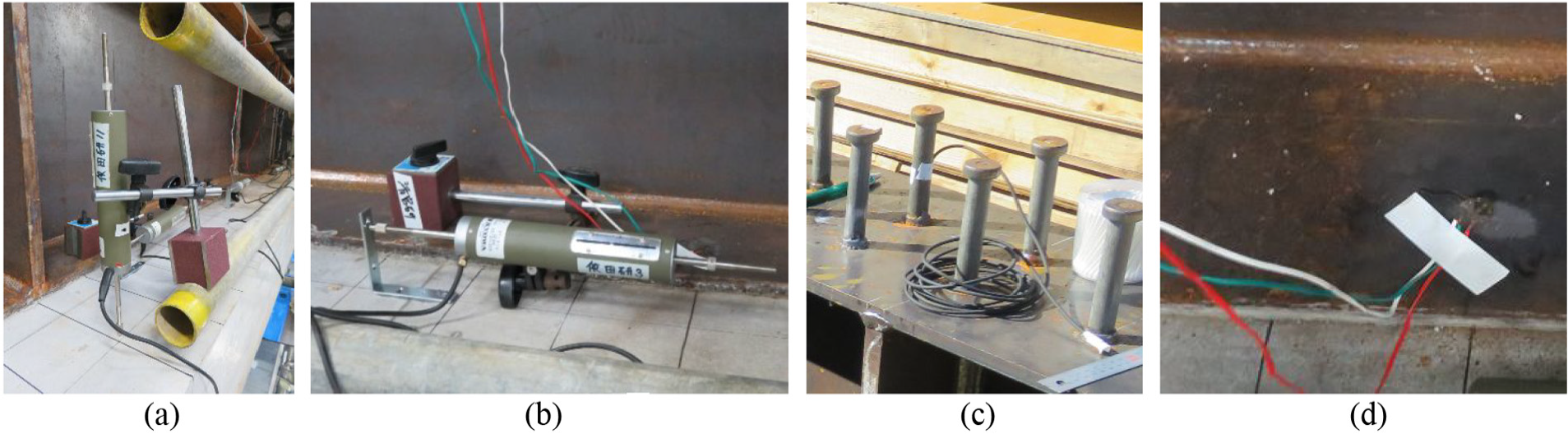
Arrangements of LVDTs and strain gauges: (a) displacement, (b) interface slip, (c) strain gauge on stud, and (d) strain gauge on steel girder.
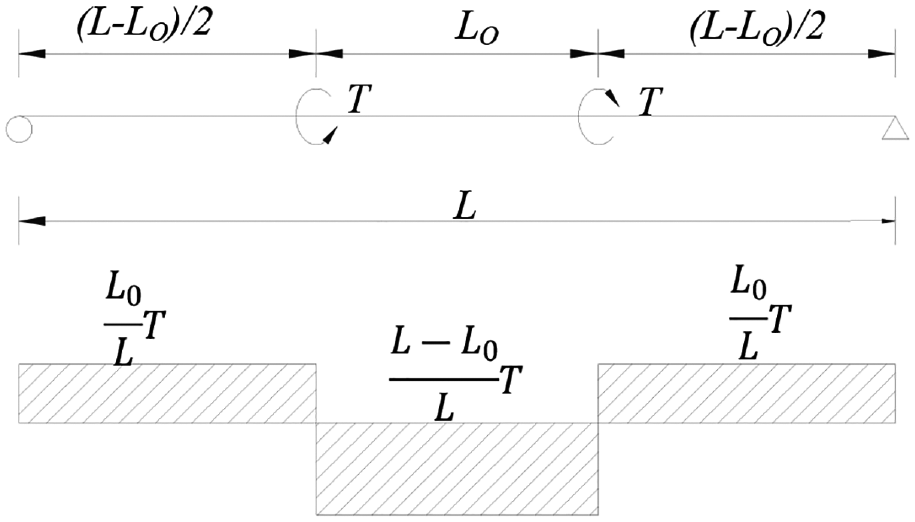
Internal torsional moment diagram.
Test set-up and loading procedure
The 5000 t loading capacity equipment of “Two Axes Large-scale Apparatus used for Performance Evaluation of Structures” was used in this experiment to apply load on the overturned composite beam. After the drying shrinkage had stabilized, pre-loading was applied to check the reliability of the measuring equipment and the stability of the test specimens. The test specimen was supported by a roller system at two ends. The set-up for the composite steel-concrete beam tests is illustrated in Figure 5.
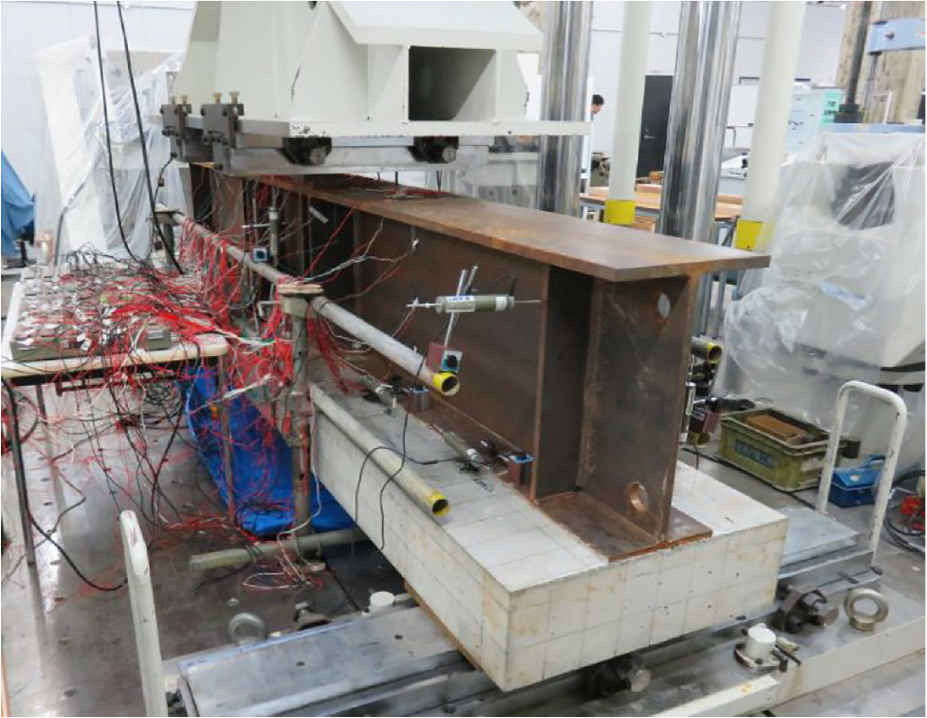
Loading test setup.
A two-stage (stage-1 and stage-2) loading test was performed on specimen-1, while the one-stage (stage-2 only) loading test was performed on specimen-2. For specimen-1, standard four-point flexural test (load applied in the beam axis, thus no torsion) was first performed to confirm the applicability of current beam theories. In stage-1, the load was applied to 260 kN (initial cracking load) to avoid the cracking of the concrete slab. After that, the load was applied with an eccentricity of 10 cm to produce to create the combined torsion and negative bending moments, as shown in Figure 1. The negative bending and torsion were applied by static loading with the unloading process at the levels 260 and 880 with loading rates of 0.004 mm/s and 0.008 mm/s, respectively. Displacement control was used in the tests with a loading rate of 0.01 mm/s for the subsequent experiment. For specimen-2, however, the stage-1 loading test was ignored and only the stage-2 loading test (with an eccentricity of 15 cm) was performed.
Material properties
Concrete cylinders of 10 cm (diameter) × 20 cm (height) were prepared for compressive tests during the casting of the concrete slab. The concrete compressive strengths achieved after 28 days of curing were 28.8 MPa, 29.5 MPa, 29.5 MPa, respectively, with the average compressive strength of 29.3 MPa. The structural steel of SMA490 (nominal yield strength: 335 MPa, nominal ultimate tensile strength: 490 MPa) was used for the steel main girder. According to the materials test, the yield and ultimate strengths of the bottom flange (t = 25 mm) are 424 MPa and 544 MPa, respectively. For the web (t = 22 mm), the yield and ultimate strengths are 437 MPa and 556 MPa, respectively. While for the top flange (t = 16 mm), the yield and ultimate strengths are 440 MPa and 568 MPa, respectively. As for the reinforcement, the SD345 has the nominal yield strength of 345 MPa and the nominal ultimate tensile strength of 490 MPa was employed. According to the materials test, the yield and ultimate strengths are 404 MPa and 608 MPa, respectively.
Test results and discussion
Load-deflection curves and failure modes
Linear variable displacement transducers (LVDTs) were installed at both loading points and girder ends to measure the vertical deformation at the loading points and support locations, as shown in Figures 1 and 5. In the load-displacement curve, the vertical displacement was taken at concrete slab below two loading points, and the load denotes the total applied load. The applied load (P)-vertical displacement (δ) relationships of the two specimens obtained from the loading tests are shown in Figure 6.
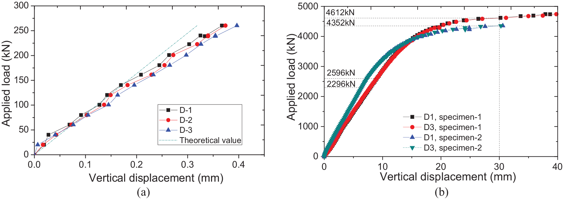
Load (P)-displacement (δ) relation: (a) elastic stage (ST-1, without torsion) and (b) whole loading process.
As described above, the elastic loading test (without torsion) was performed in the specimen-1, and the applied load versus vertical displacement curve is shown in Figure 6(a). The comparison between the results at two loading points shows that the displacements were similar to each other, indicating that the load was applied evenly at two loading points. In addition, the load-displacement relationship of the test specimen based on classic beam theories was also provided. Although a slightly difference was observed, relatively good agreement between test results and theoretical results was confirmed, demonstrating that the classic beam theory works well in predicting the behavior of the test specimens under the designated loading condition.
The applied load versus vertical displacement relationship of the test specimens during the whole loading stage is shown in Figure 6(b). The comparison shows that the rigidity of specimen-1 is smaller than that of the specimen-2 in the initial loading stage. Two eccentric loads were applied to induce the torsion moments in this study. Due to the limited distance between the two load points, the composite beam between two loading points behaves like a “deep beam,” thus the “shear lag” affects more on that of specimen-2 than on specimen-1. On the other hand, the yield of specimen-1 was determined as 2596 kN, which was nearly 11.6% higher than that of the specimen-2 (2296 kN). The yield of the test specimen was firstly confirmed on reinforcement in the span center section, and the yield load was determined accordingly. As the loading test of specimen-2 was terminated when the displacement was around slightly over 30 cm due to the severe cracking of the concrete slab, the ultimate load can be approximately taken as the load corresponding to the vertical displacement of 30 cm. In this condition, the ultimate load of specimen-1 and specimen-2 can be determined as 4612 kN and 4352 kN, respectively, hence a 5.6% reduction can be confirmed.
After the loading test, through cracks of the concrete slab were confirm in both test specimens, as shown in Figure 7(a). For the specimen-1, the plate hinge of the bottom flange of the steel girder was also confirmed (Figure 7(b)), which is caused by the torsion due to eccentric loading. Therefore, severe cracks on the concrete slab and the possible plate hinge of the bottom flange of the steel girder is the failure mode for steel-concrete composite beams subjected to combined negative bending and torsional moments. Two specimens after the loading tests were shown in Figure 7(c) and (d), respectively.
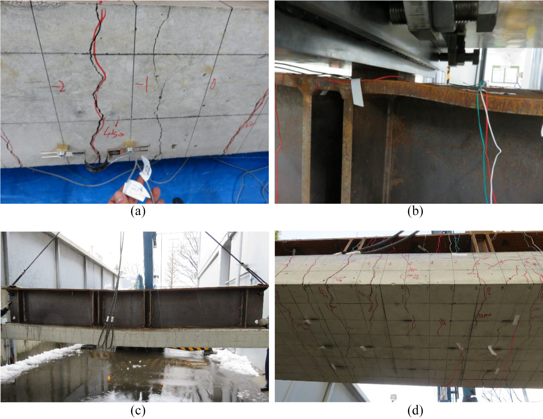
Failure mode of the test specimen: (a) through cracks on the concrete slab, (b) plate hinge of the bottom flange, (c) specimen-1 after the loading test, and (d) specimen-2 after the loading test.
Strain on the steel girder
To investigate the normal strain distribution on the steel girder near the loading points, four strain gauges (referred to as S1, S2, S3, and S4, respectively) were attached on the surface of the bottom flange. As shown in Figure 1(b), S1 and S2 were used on section A-A, while S3 and S4 were attached on section B-B.
The applied load-normal strain relationships were illustrated in Figure 8. The results in Figure 8(a) indicate that, in the initial loading stage, the normal strain increased linearly with the increase of the applied load. When the applied load increased to a certain value, however, the strain of S1 increased significantly while the strain on S2 still kept increasing linearly. Thereafter, the strain of S1 increased nonlinearly, and a sudden increase was observed when the applied load was 3446 kN, which was presumably due to the yielding of the bottom steel flange. By also considering the deformation of the steel flange observed on the loading point as shown in Figure 7(b), it can be concluded that eccentric load can cause a significant difference in stress distribution between the loaded and un-loaded side of the steel flange. Such uneven stress distribution might be the cause of the reduction of the load-carrying capacities, as confirmed above. Similar results were also observed on section B-B, as shown in Figure 8(b).
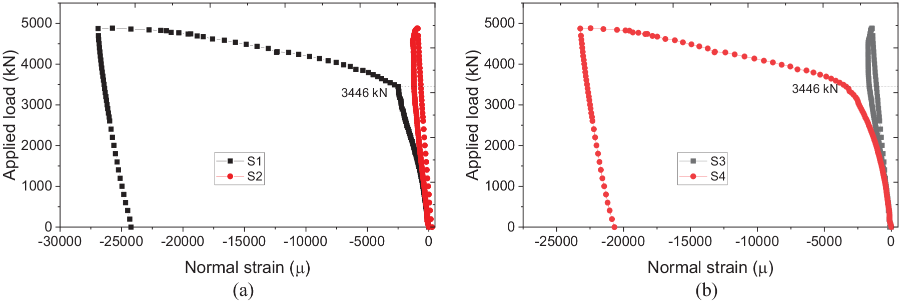
Normal strain on the steel girder: (a) section A-A and (b) section B-B.
Strain on the shear connectors
Shear connectors are key mechanical devices used between steel girder and concrete slab to provide the means to achieve composite action on the steel-concrete interface, thus increasing both stiffness and strength of composite beams. Stud shear connector is one of the most popular types, which is also used for the test specimens in this study.
To investigate the mechanical behavior of the shear connectors in composite beams subjected to combined negative bending and torsion, both shear strain gauge and normal strain gauge were used to at the foot of the studs in the test specimen. The measurement of shear and normal strain on stud shear connectors is shown in Figure 9. Shear strain gauges were attached at the side surface of the stud connectors to measure the shear strain. Normal strain gauges, however, were used at both front and back surfaces of the stud connectors to measure the compression strain (ε C ) and tensile strain (ε T ) respectively. Therefore, the strain due to axial force (ε N ) and the strain due to pure bending (ε B ) are determined as:


Several studs were measured in the loading tests, and the results of 10 studs were summarized and reported in this paper. Five studs (Stud-1∼Stud-5) were measured to investigate the shear strain distribution, while the other five studs (Stud-6∼Stud-10) were measured to confirm the strain due to bending moment and axial force on shear connectors. As described above, the two stages loading process was applied for specimen-1. In loading stage-1, a standard four-point flexural test (without torsion) was firstly performed for specimen-1 (similar test was not performed on specimen-2), and the shear strain incensement with the load is shown in Figure 10. Also, the theoretical value was provided to make a comparison. In theoretical calculation, “perfect bonding” is assumed for the steel-concrete interface and no-slip is considered. The results indicate that the shear strain of the stud increases linearly with the increase of the applied load. Also, relatively good agreement between the measured values and the theoretical values was confirmed, demonstrating the validity of the “perfect bonding” assumption for the composite beams in the initial loading stage. Thereby, it confirms again that the classic beam theory can predict the structural behavior of the test specimen very well.
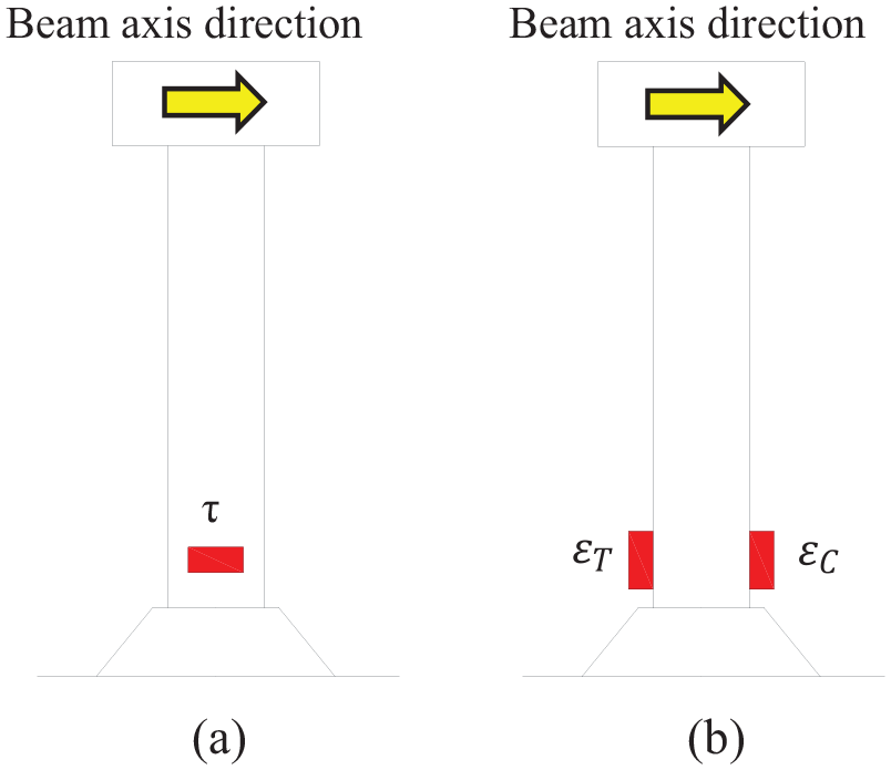
Strain measurement on shear studs: (a) shear strain gauge and (b) normal strain gauge.
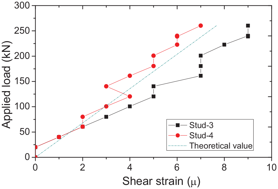
Applied load-shear strain relationships on studs (without torsion).
In the loading stage-2, a four-point flexural test with torsion was performed, and the incensement of shear strain, flexural strain and axial strain with the increase of the applied load of two specimens are shown in Figures 11 and 12, respectively. The shear strain of studs versus applied load relationships in specimen-1 are shown in Figure 11(a). The results indicate that the shear strains of Stud-1∼Stud-4 increase gradually with the increase of the load, but the shear strains of Stud-1 and Stud-2 were smaller than those in Stud-3 and Stud-4. A similar phenomenon was observed from previous tests (Lin et al., 2014b), which was due to the friction forces at the beam ends caused by reaction frame restriction. The shear strains of Stud-5 were relatively small during the whole loading process due to the near-zero shear force zone between the two loading sections. Similar results were also observed in specimen-2, as shown in Figure 12(a).
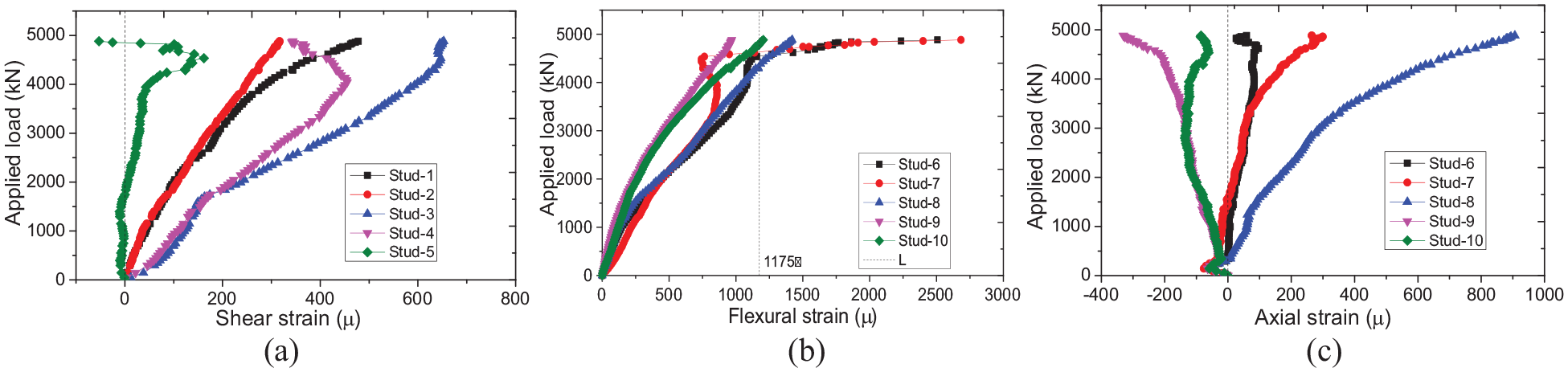
Applied load-strain relationships on studs (specimen-1): (a) shear strain, (b) flexural strain, and (c) normal strain.
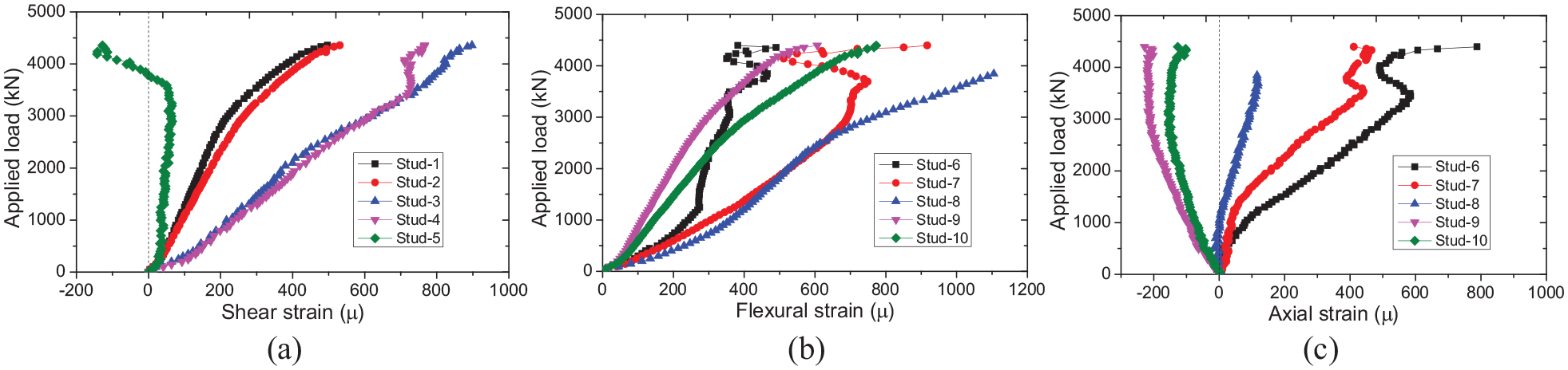
Applied load-strain relationships on studs (specimen-2): (a) shear strain, (b) flexural strain, and (c) normal strain.
The flexural strain versus applied load relationship of specimen-1 is shown in Figure 11(b). An interesting phenomenon is that the flexural strains of stud were no smaller than the shear strains. In the current design specifications, only shear forces were considered in the design of shear connectors. In this study, however, the flexural strain of shear connectors was even larger, and the flexural strain of studs in specimen-1 even reached the yield strength (as shown in Figure 11(b)), indicating the yield of the studs in the ultimate loading condition. The steel material of SS400 was used for stud connectors, and the nominal yield strength is 235 MPa, and the yield strain of 1175 µ can be assumed accordingly. Therefore, flexural strains of studs are non-negligible and should be considered in the design of shear connections.
The normal strains due to axial forces of five four shear stud connectors (Stud-6∼Stud-10) were shown in Figure 11(c). The results indicate that the normal strain of Stud-9 and Stud-10 were negative, indicating the compressive axial forces in these two stud shear connectors, which might be due to the reaction forces. The normal strains of the other three studs, however, were always positive, demonstrating the tensile axial forces of these studs as well as the separation tendency between the concrete slab and the steel main girder. Also, although the normal strains due to axial forces were smaller than those due to bending moment, they are non-negligible in the design of shear connectors in such structures.
All in all, the results obtained in this study indicate that there are non-negligible normal strains caused by bending moment as well as the axial forces in addition to the shear forces in steel-concrete composite beams subjected to combined negative bending and torsion, which can significantly affect the performance of the shear connectors thereby affect the global behavior of the composite beams. Therefore, the design method of shear connectors in such structures deserves further studies.
Interface slip development
Linear variable displacement transducers (LVDTs) were used on key sections (gauge stand on the steel while the “L” shape embedded part on the concrete as shown in Figure 3(b)) to measure the relative displacement between the steel top flange and the concrete slab, or the slip on the steel-concrete interface.
The applied load versus slip relationships of the two specimens were shown in Figure 13. The results indicate that the interface slip near the 1/4 span was much larger than those observed at both ends. It is presumably caused by the following two reasons: (1) the friction forces at the beam ends caused by reaction frame restriction; (2) the severe cracks on the concrete slab also contribute to a certain amount of slip measured in the cracking zones. But also taking the phenomenon of shear strain distribution of shear connections into consideration, it can be concluded that the interface slip at the girder end sections is generally affected by the friction forces and thus smaller than those measured in 1/4 span of the test specimens.
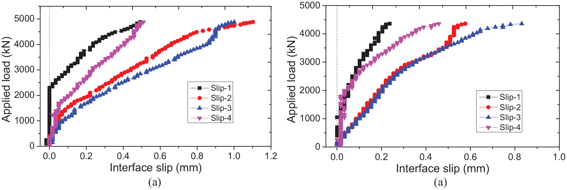
Applied load-slip relationships on steel-concrete interface: (a) specimen-1 and (a) specimen-2.
Concluding remarks
Four-point flexural tests with and without torsion were performed in both elastic and plastic loading stages to investigate the steel-concrete composite beams under combined negative bending torsion. Detailed test results involving applied load versus displacement relationship, applied load versus strain relationships on steel main girder and shear connectors as well as slip on the steel-concrete interface were recorded in the test and reported in this paper. From the results presented herein, the following conclusions and recommendations deserving priority are made:
(1) The theoretical results determined according to the current elastic design theory, including both displacements and strains on shear connections etc. agree well with the test results. Therefore, steel-concrete composite beams under negative bending moment can be designed appropriately according to the current design method.
(2) For steel-concrete composite beams subjected to combined negative bending and torsional moments, the presence of torsion will result in a decrease of the bending moment capacities. The reduction of both yield load and ultimate load of the specimens was confirmed.
(3) Typical failure mode of the steel-concrete composite beams subjected to combined negative bending and torsional moments is the through cracks of the concrete slab as well as the bucking of the top flange of the steel main girder.
(4) For stud shear connectors in such beams, normal strains caused by bending moment and axial forces are non-negligible compared to the shear strains. In addition to shear forces, bending moment and axial forces should also be considered in the design of shear connectors in composite beams.
(5) The interface slip near the 1/4 span was larger than those observed at both ends, which is presumably due to the friction forces at the beam ends caused by reaction frame restriction.
For the future study, a numerical model capable of simulating the structural behavior of the test specimen used in this study should be built. The parametric studies will be performed, and the negative bending-torsion interaction relationship will be investigated for steel-concrete composite beams subjected to combined negative bending and torsion. Also, a more straightforward application of torsion can benefit the investigation of the effectiveness of torsion on the stiffness of such beams.
Footnotes
Declaration of conflicting interests
The author declared no potential conflicts of interest with respect to the research, authorship, and/or publication of this article.
Funding
The author disclosed receipt of the following financial support for the research, authorship, and/or publication of this article: This research is sponsored by the Grant-in-Aid for Young Scientists B (15K18108) from the Japan Society for the Promotion of Science (JSPS) (Grant recipient: W.L.). The financial support is gratefully acknowledged.