
Abstract
U75V rail steel rods underwent continuous-drive friction welding (CDFW). Joint properties were evaluated through microstructural analysis and mechanical testing (tensile, impact, and microhardness). The thermo-mechanical behaviour of the CDFW process was simulated by the finite element method, while a computed continuous cooling transformation diagram was used to predict phase transformation, microstructures, and hardness variations. By reducing the spindle speed to 1000 r/min, the peak temperature in the weld centre zone (WCZ) remained below Ac1. Microstructures in WCZ exhibited a high density of geometrically necessary dislocations. The joints demonstrated comparable tensile strength, impact toughness, and microhardness to BM, with underlying mechanisms elucidated. This study showcases CDFW's potential in achieving rail steel joints with quasi-equal strength and toughness to the BM.
Introduction
Seamless rail lines are commonly joined using various welding technologies, such as stationary flash butt welding (FBW) in rail welding plants, followed by mobile FBW, gas pressure welding (GPW), and thermite welding at rail track laying sites.1,2 Despite their widespread use, these welding methods often encounter a significant challenge: the weld thermal cycles and subsequent post-weld heat treatment (PWHT) can result in a non-uniform surface hardness zone spanning tens of millimetres. 3 This zone comprises both hardened and softened subzones, 4 leading to mechanical property discrepancies between the joined region and the steel rail itself.5,6 Additionally, these welded joints are required to withstand the same load of rolling contact fatigue as the high-strength steel rail during their service. 7 The presence of such zones increases the likelihood of uneven wear, which in turn can cause defects like bumps, low collapses, scratches, and so on. 8 These defects can compromise the performance of seamless rail lines over time, adversely affecting the safety, stability, and high-speed operation of trains. 9 Therefore, minimising the discrepancy in mechanical properties between welded joints and the steel rail is crucial for ensuring the long-term performance of seamless rail lines as well as the operational stability and safety of trains. 10 This remains an ongoing challenge for researchers and engineers.
Continuous-drive friction welding (CDFW) is a solid-state joining process that utilises relative movement between workpieces to generate frictional heat for welding. In this process, the workpieces undergo initial high-speed rotation against each other with friction pressure, then forge under enough upsetting pressure, leading to material deformation and eventually merging into a solid, homogeneous joint. 11 CDFW is highly efficient, energy-saving, and capable of preserving the original properties of the being joined base metal (BM) within the welded joint to a large extent. 12 In addition, careful control of process parameters such as low spindle speed and adopting appropriate axial pressure in the frictional stage of CDFW could minimise welding heat input, effectively reducing the risk of harmful microstructures and defects generation within the welded joint. 13 For steel materials, maintaining the peak temperature of the weld interface below Ac1 could preserve the strength and toughness of BM within welded joint. Morisada et al. attempted to weld S45 high-carbon steel using CDFW below Ac1 temperature and obtained strength-toughness trade-off joints. 14 Recently, it has been demonstrated that by optimum welding process parameters, friction welding could be performed by rapid heating and cooling. Under the combing effect of pressure and relatively low peak temperature, the grain-boundary and dislocation strengthening effects were generated, achieving sound as-welded joints. 15 Thus, CDFW is an attractive option for joining difficult-to-be-welded materials such as high-strength steels and has potential application prospects in the railway industry, including seamless rail line welding. Harnessing CDFW enables the creation of high-caliber, dependable rail welded joints capable of enduring the rigours of heavy-duty railway operations over extended periods.
This study aims to investigate an innovative friction welding technique and develop a corresponding device specifically designed for welding steel rail. This paper demonstrates the feasibility of minimising the mechanical property difference between the as-welded joints and the rail steel while utilising CDFW to weld rail steel rods below Ac1 temperature. The grain-boundary and dislocation strengthening effects associated with low-temperature CDFW enable the production of welded joints that exhibit quasi-equal strength and toughness compared to the rail BM without compromising toughness. This eliminates the need for subsequent PWHT.
Methods
The material to be welded is U75V (Pangang Group Co. Ltd) rail steel rods with a size of Φ12 × 60 mm and a 0.75C-1.00Mn-0.65Si-0.08 V wt.% composition. The mechanical properties of the U75V are with Rm ≥ 980 MPa, A ≥ 10%, and 280∼320 HBW (or 295∼337 HV). Its microstructure is an inhomogeneous agglomerate of lamellar pearlite and a small amount of ferrite. 16
The HSMZ-4 CDFW machine manufactured by Harbin Welding Institute was used for welding U75V rail steel rods. This machine is equipped with a maximum spindle speed of 2800 r/min and a full upsetting force of 4 t, and is capable of welding cylindrical rods and pipes up to 30 mm in diameter. 17 The spindle speed (Ss), friction pressure (Fp), friction time (Ft), upsetting pressure (Up), and upsetting time (Ut) are the main process parameters that can be adjusted in a CDFW process. These parameters determine the amount of frictional heat generated during the process, the level of plastic deformation, and the final microstructure and mechanical properties of the welded joint.
During the CDFW process, one rail steel rod affixed to the motor spindle initiated rotation at a predetermined and constant spindle speed denoted as Ss. Subsequently, another rail steel rod positioned on a mobile jig moved towards the rotating rod. As the two rods were in contact, a preset friction pressure termed Fp was applied. Throughout the friction stage, with Ss and Fp remaining constant for a preset period denoted as Ft, substantial frictional heat emerged at the contact surface of the two rods, leading to heating and softening of the adjacent material. Following this, the upsetting stage ensued, during which a preset upsetting pressure termed Up was applied for a designated upsetting time referred to as Ut. Sufficient plastic deformation was generated to force the two rods to join. The entire process was completed in seconds.
To achieve the desired mechanical properties of the welded joint, the CDFW process needs to be optimised; it entails determining an optimal combination of process parameters, such as Ss, Fp, Ft, Up, and Ut. Accurate control of these parameters enables the regulation of welding heat input and plastic deformation. It ensures the production of a sound metallurgical bond in the welded joint while achieving quasi-equal matching with the strength and toughness of the BM. 13 This study aims to identify a feasible combination of process parameters by intentionally decreasing Ss while keeping the other parameters constant and evaluating the joint's performance. Three different process parameter combinations with the same axial pressure of Fp = 50 MPa and Up = 150 MPa and stage time of Ft = 4 s and Ut = 4 s but varying Ss = 1000 r/min (Trial I)/1200 r/min (Trial II)/1400 r/min (Trial III) were conducted.
After undergoing CDFW, the welded joints were subjected to standard metallographic sectioning and preparation procedures and treated with a 4 vt. % nitric acid alcohol solution for 25 s to acquire metallographic specimens. The microstructures of the specimens were analysed using an Olympus BX51RF optical microscope and a Zeiss Gemini SEM 300 scanning electron microscope (SEM) equipped with an electron backscattered diffraction (EBSD) system (Symmetry G2 detector by Oxford Instruments). During the SEM analysis, the electron beam was set to an acceleration voltage of 20 kV, an aperture size of 120 μm, and the specimen was tilted by 70°. The post-processing of the EBSD data was conducted using the AztecCrystal software. Furthermore, Vickers hardness distributions were measured utilising a microhardness tester (Future-Tech FM-800) under a 500-gf load, a 15 s dwell time, and an interval of 0.2 mm between each testing point. The testing processes were done following ISO standard 6507-1:2018. 18
The tensile tests were performed using an Instron 5980 universal testing system with a 2 mm/min tensile rate. The preparation of tensile specimens and the testing processes were done following ISO standard 6892-1:2019 19 and the Chinese railway industry standard TB/T 1632.2-2014. 20 The Charpy impact tests were conducted on small-size (55 × 10 × 5 mm) impact specimens using a ZBC series impact testing machine. The preparation of impact specimens and the testing processes were done following ISO standard 148-1:2016 21 and TB/T 1632.2-2014.
Experimental results
Microstructure of the CDFW joints
Figure 1 presents the cross-section morphologies of the joints for Trials I∼III and the schematic diagram. Compared with the BM, significant changes in the microstructure of the weld zone (WZ) are observed, accompanied by a hyperbolic shape at the boundary between the WZ and BM. The width of WZ was found to increase with the ascending values of Ss, with the narrowest WZ width in Trials I∼III being 625.6, 1025.5, and 2057.0 μm, respectively, as depicted in Figure 1(a). For more in-depth analysis, WZ could be further divided into two subzones: the weld centre zone (WCZ), located around the rod centre axis, and the weld periphery zone (WPZ), situated approximately 3∼5 mm radially away from the rod centre axis, as shown in Figure 1(b). It is noticed that continuous ‘bright’ zones are evident throughout the WZ of Trials II and III, while in Trial I, the ‘bright’ zones only appear in WPZ. The WCZ of Trial I appears to be ‘dark’ zones that were distinct from other subzones, as illustrated in Figure 1(a). Further analysis of the microstructure of WZ was conducted through SEM and EBSD.
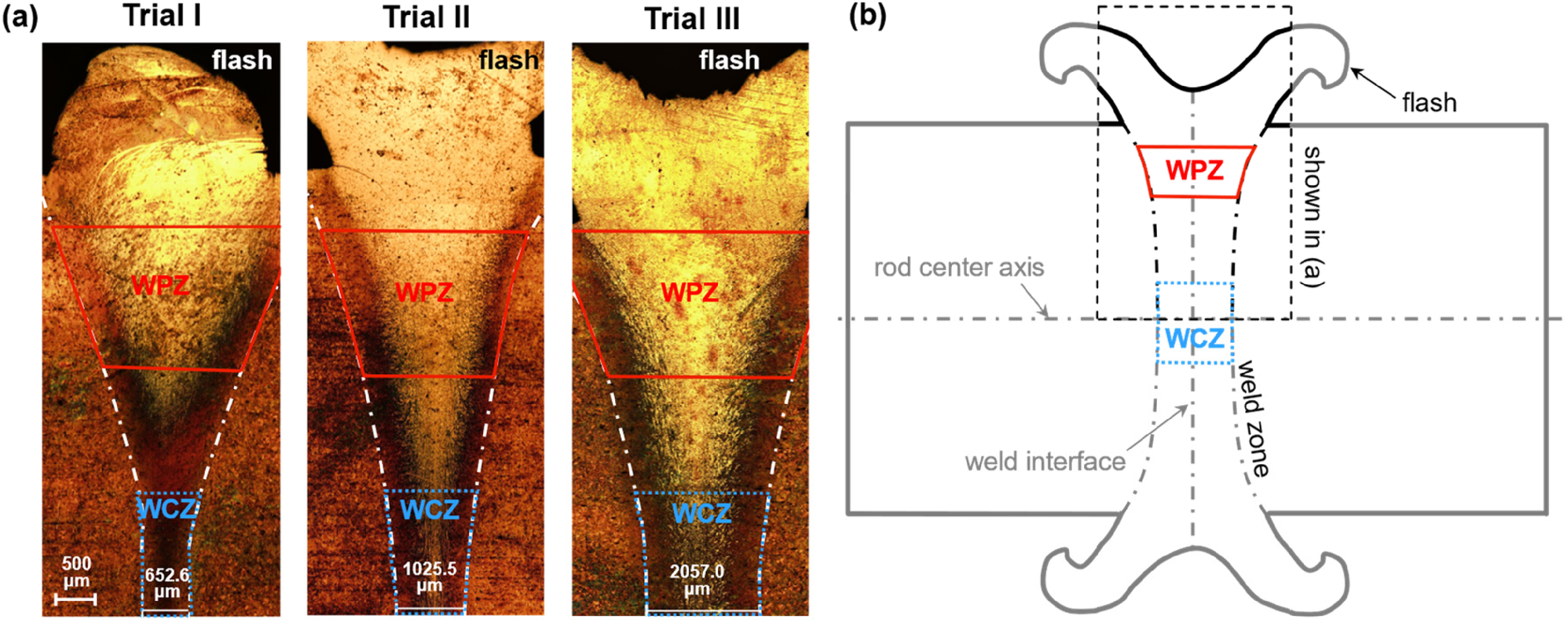
Optical morphologies of the weld cross-section for Trials I, II, and III (a) and the schematic diagram (b).
Figure 2 depicts the SEM images of WCZ and WPZ for Trials I and III, respectively. Figure 2(b)–(d) shows the presence of coarse-grained martensite and retained austenite (RA) microstructures corresponding to the ‘bright’ zones. Conversely, Figure 2(a) exhibits a distinctive microstructure from the other images, with finer grains dynamic recrystallization (DRX) microstructures corresponding to the ‘dark’ zones.
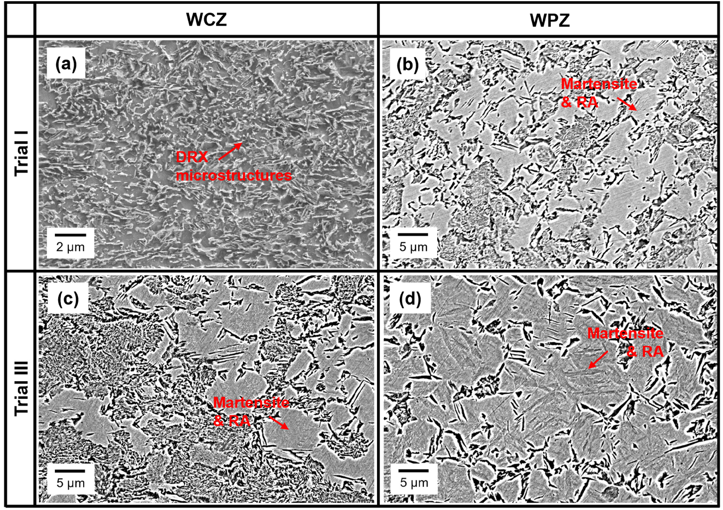
SEM images of WCZ and WPZ for Trial I and III: (a) WCZ of Trial I; (b) WPZ of Trial I; (c) WCZ of Trial III; (d) WPZ of Trial III.
Figure 3 portrays the EBSD analysis results for different subzones of Trial I. The inverse pole figure (IPF) maps demonstrate discernible differences in grain size among these subzones, along with the BM. The microstructure of the BM consists of elongated grains oriented along the rolling direction, with an average grain size of approximately 40 μm, as illustrated in Figure 3(e). Conversely, significant grain refinement is observed in WZ, where the elongated grains undergo a transformation into equiaxed grains. This transformation is attributed to the occurrence of DRX induced by the combined effects of severe plastic deformation and heat generation during the CDFW process. The grain size of WCZ is finer than that of WPZ, as shown in Figure 3(a) & (b). The average grain diameter in WCZ was found to be 1.8 ± 0.8 μm using the circle equivalent diameter method, which is smaller than that of WPZ (4.3 ± 1.4 μm). The phase maps are illustrated in Figure 3(d) & (e), and their microstructures are dominated by body-centred cubic (BCC) structures, but 5.2% of face-centred cubic (FCC) structures appear in WPZ.
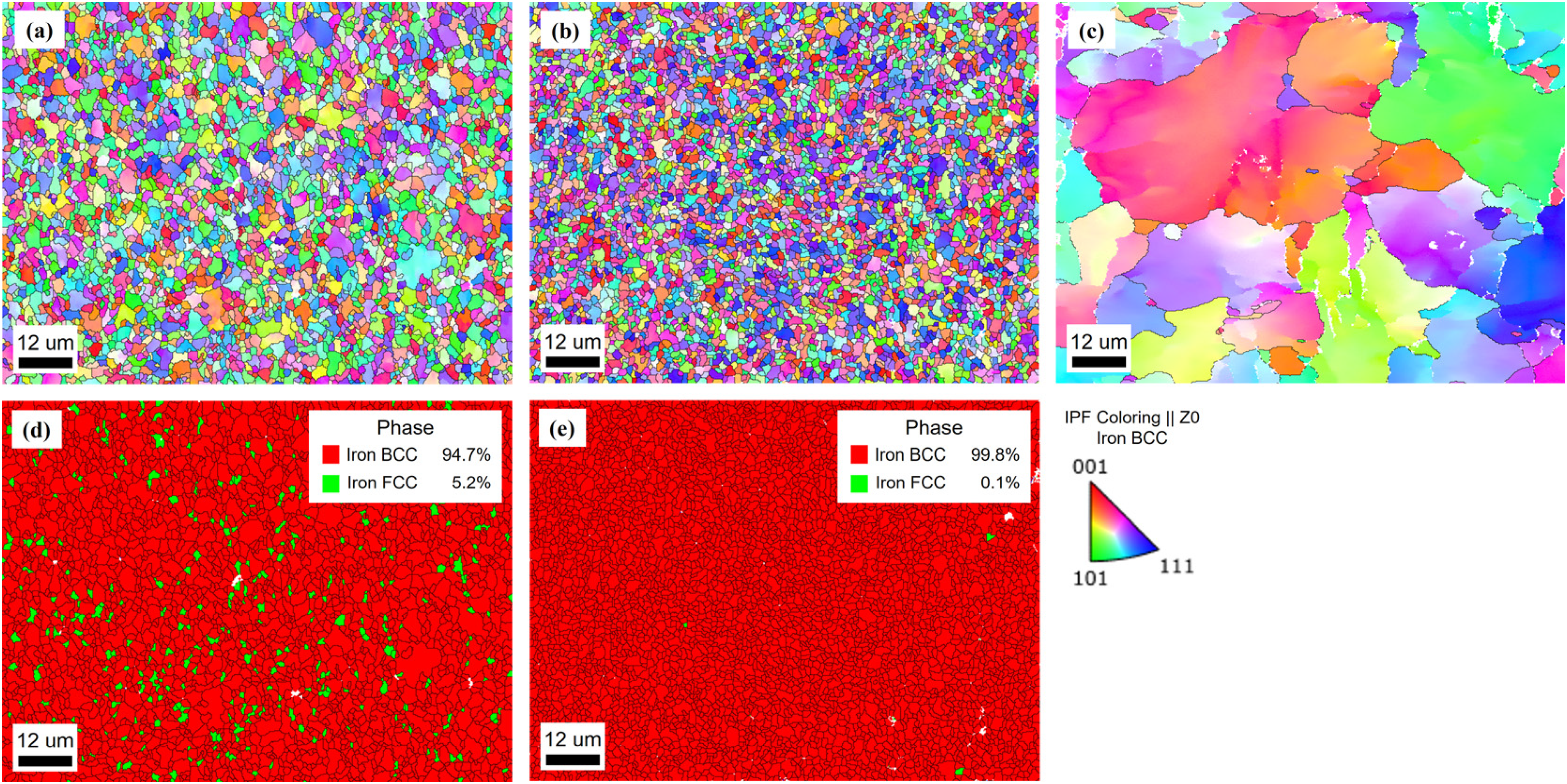
EBSD maps of the as-welded joint in Trial I: IPF maps of WPZ (a), WCZ (b), together with that of BM (c); phase maps of WPZ (d) and WCZ (e).
Hardness measurement
Figure 4(a) shows the Vickers hardness distribution along the WCZ (solid lines) and WPZ (dashed lines) of Trials I∼III. As the WZ is symmetrically distributed, the microhardness of only one side is presented, as the schematic diagram shown in Figure 4(b). It could be observed that significant increases in hardness occurred throughout the WZ of Trials II and III and the WPZ of Trial I. The hardness increase trend in WPZ is higher than that in WCZ. In contrast, the peak hardness of the WCZ in Trial I is only 342.9 HV, which is very close to the hardness of BM (295∼337 HV).
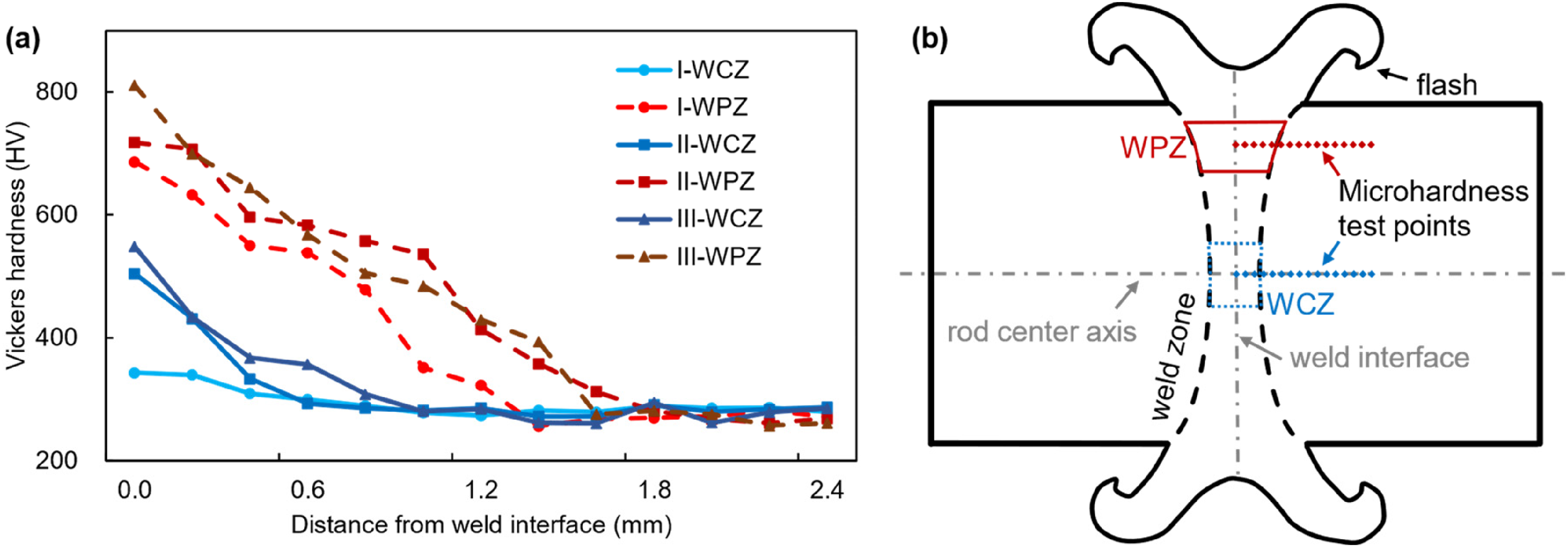
Vickers hardness of WCZ and WPZ for Trials I, II, and III (a) and the schematic diagram (b).
Tensile test
Tensile properties are characterised by the ultimate tensile strength (Rm) and percentage elongation after fracture (A). The test results are shown in Figure 5(a). The tensile properties of Trial I are better than those of Trials II and III. The Rm for Trial I is 933.0 ± 2.6 MPa, surpassing 90% of that of the BM (1035.6 MPa). While other welding methods (e.g. FBW, GPW) usually require PWHT to make the Rm reach 90% of that of BM (980 MPa) to satisfy the requirement of Rm ≥ 880 MPa, for 980 MPa grade rail steel in TB/T 1632.1-2014. Besides, the A for Trial I is 6.0±0.5%, which also meets the requirement of A ≥ 6.0% in TB/T 1632.1-2014.
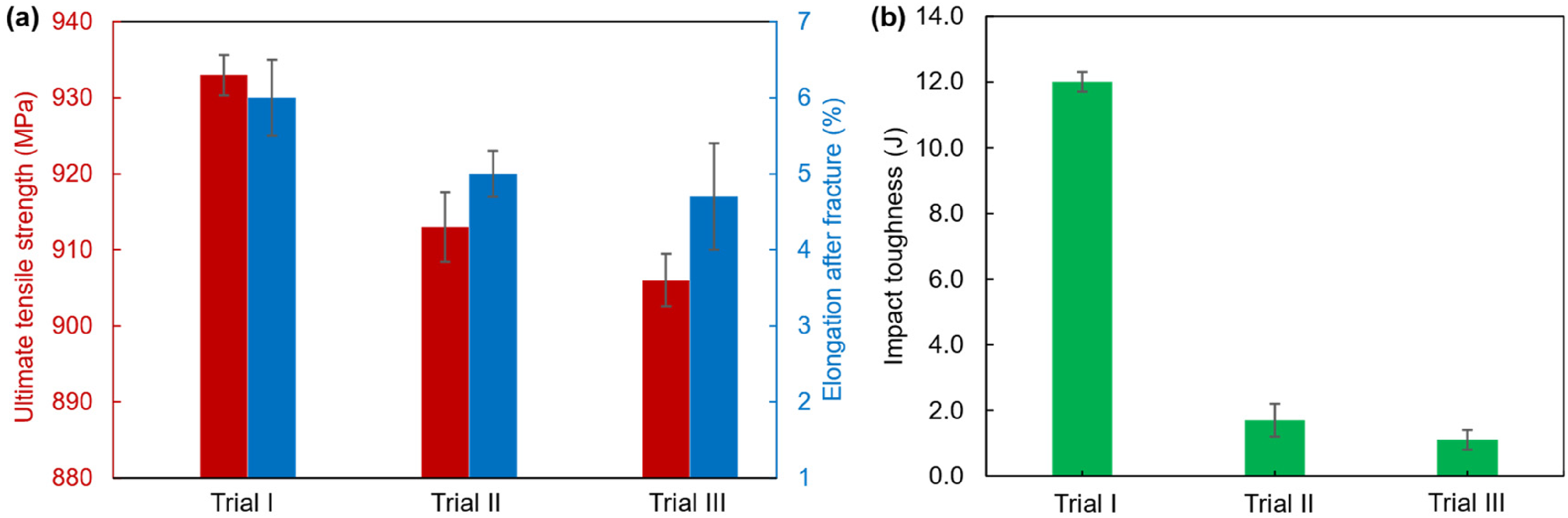
Tensile properties (a) and impact toughness (b) for Trials I∼III.
Impact toughness test
The impact toughness is characterised by impact absorption energy (KU2), representing the absorbed energy of the small-size impact specimen with a height of 5.0 mm and its U-shape notch with a radius of 2 mm, and the test results are shown in Figure 5(b). The KU2 for Trial I is 12.0 ± 0.6 J, close to that of the BM (12.94 J). 22 The results far exceed the KU2 of Trials II and III and other welding methods (e.g. FBW, GPW) and the KU2 standard in TB/T 1632.1-2014 (≥6.5 J). Moreover, the welded joints obtained by other welding methods often need PWHT to meet the requirements of the KU2 standard in TB/T 1632.1-2014. 23
Modelling and simulations
To comprehensively and systematically investigate the coupled thermo-mechanical behaviour of the CDFW process, a finite element (FE) model was developed in the ABAQUS 6.14-5 environment. U75V rail steel material properties were obtained from, 24 and the elastic-viscoplastic constitutive model was derived from the stress-strain behaviours at different temperatures and strain rates presented in Reference. 25 The isotropic work-hardening effect was considered, especially in cases of temperatures around the Ac1 threshold and relatively high strain rates. A sliding and sticking friction heat generation model was adopted. The setting of the friction coefficient was temperature-dependent to balance the varying heat fluxes during CDFW process, as discussed in. 26 Besides, the density, specific heat, thermal conductivity, thermal expansion, Young's modulus, and Poisson's ratio were also temperature-dependent. As the rods exhibit axial symmetry, a 2D axisymmetric transient fully coupled temperature-displacement analysis method was adopted to construct the model. 27 The rods were modelled as deformable bodies and discretised using the axisymmetric element CGAX4T, consisting of nodes encompassing freedom degrees of temperature, displacement, and twist. Due to the severe deformation near the interface, the FE quadrilateral mesh was divided into three sections: the upper part, with a length of 6 mm, had a meshing size of 0.2 mm; the middle part, also with a length of 6 mm, had a meshing size of 1 mm; and the lower part, with a length of 18 mm, had a meshing size of 2 mm. This meshing configuration is illustrated in Figure 6(a). The tangential and normal behaviours, self-contact, and surface film conditions were considered via the ABAQUS interaction module, and the geometric nonlinearities were set in the step module by selecting NL Geom.
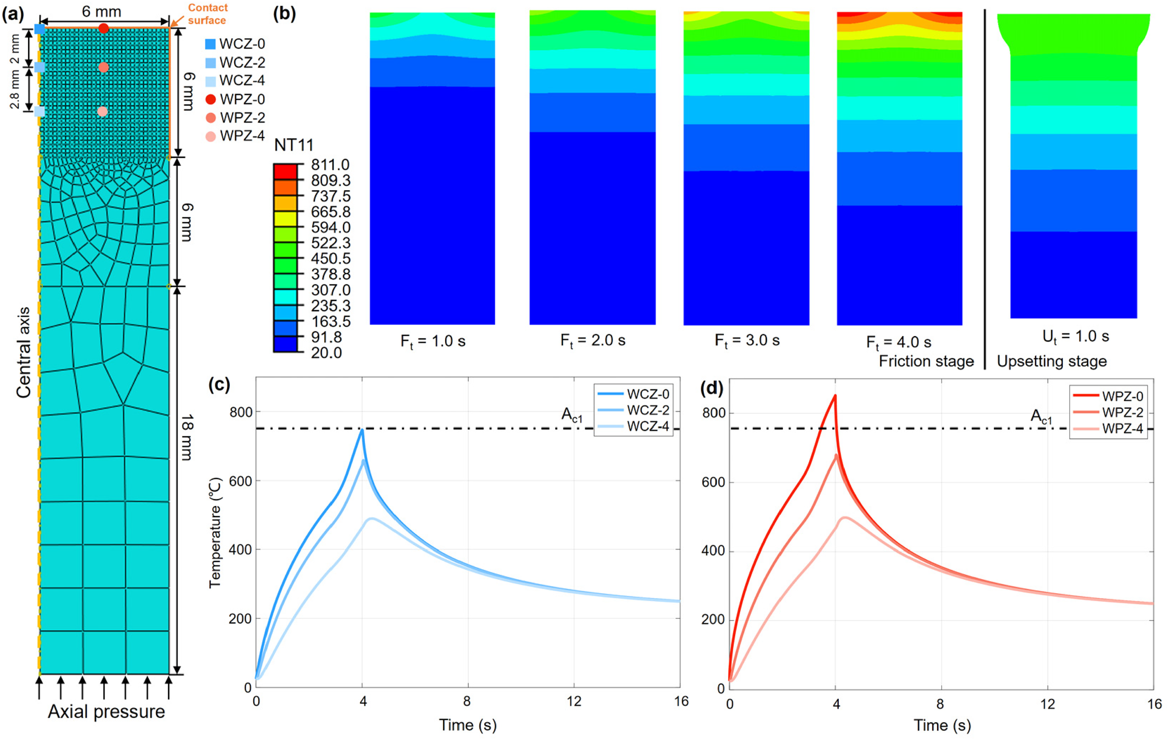
2D axisymmetric meshing model of the rod (a); simulation results of Trial I: temperature field at different times (b); and thermal cycle curves: (c) WCZ; (d) WPZ.
Figure 6(b)–(d) presents the simulated temperature field, its evolution, and the thermal cycle curves of Trial I. As shown in Figure 6(b), heat generation begins at the contact interface of the rods, and the heating zone gradually expands along the axial direction of the rod due to heat conduction as Ft increases. Meanwhile, plastic deformation occurs at the contact interface of the rods and their adjacent zones, and significant flash is eventually observed, see Ut = 1.0 s. Figure 6(c) & (d) exhibits the thermal cycle curves of various observation positions, including the central axis on the contact interface (WCZ-0) and curves at 2 mm (WCZ-2) and 4.8 mm (WCZ-4) distances from the interface, as well as the same position in the axial direction but 3 mm away from the central axis in the radial direction (WPZ-0, WPZ-2, and WPZ-4), respectively. The corresponding positions are already marked in Figure 6(a).
Simulation results demonstrate that the peak temperature of the subzone around the rod central axis is about 737.5°C, see Ft = 4.0 s, and the thermal cycle record WCZ-0 in Figure 6(c) remains below Ac1 temperature threshold. In comparison, the peak temperature at the rod periphery subzone reaches about 811.0°C, see Ft = 4.0 s, and the thermal cycle record WPZ-0 surpasses Ac1 temperature.
Discussions
The presented results reveal a positive correlation between the welding heat generation and the increment of Ss, as evident from Figure 1(a). Trial I formed a sound metallurgical bond with the narrowest WZ width. Besides, the linear speed of relative frictional motion escalates linearly along the radial direction of the rod end interface during the CDFW process, influencing the welding heat generation: at the rod periphery, where linear velocity is highest and frictional heat most intense, the WZ width is broader; In contrast, around the rod centre axial, the WZ width narrows as the linear speed reduces towards the rod centre axis, where no frictional heat is generated, resulting in the narrowest WZ width formed by heat conduction from the surrounding zone. These outcomes indicate less welding heat was generated in the WCZ of Trial I.
Furthermore, the optical morphologies in Figure 1(a), the SEM images in Figure 2, the EBSD analysis results in Figure 3, and the microhardness tests in Figure 4 collectively demonstrate significant differences in microstructures between the WCZ of Trial I and the WPZ of Trial I as well as the throughout WZ of Trials II and III. The WPZ of Trial I contains FCC structures with small grain sizes, along with the WZ of Trials II and III, exhibit increased microhardness, suggesting the occurrence of austenite transformation and DRX during the CDFW process. Within these subzones, the peak temperature surpasses the Ac1 temperature threshold, forming brittle and hard martensite and RA during the ensuing cooling stage, as validated through microhardness measurements. 22 WPZ has a sizeable relative friction linear velocity, which translates into increased welding heat input, thus resulting in the generation of additional austenitic microstructures, which, in turn, leads to heightened microhardness levels. On the other hand, the WCZ of Trial I displays BCC structures with smaller grain sizes and a microhardness comparable to that of the U75V BM. This indicates that this subzone sustains DRX without undergoing austenite transformation. The DRX process involves grain nucleation and growth at temperatures below Ac1, resulting in distinctly different microstructures. These differences can be attributed to the lower welding heat input in the vicinity of the rod centre axis and the presence of axial pressure.
A comprehensive EBSD analysis was performed to investigate the microstructures in the WCZ of Trial I. The kernel average misorientation (KAM) values were utilised to quantify the local misorientations, which enabled the derivation of the geometrically necessary dislocations (GNDs) density

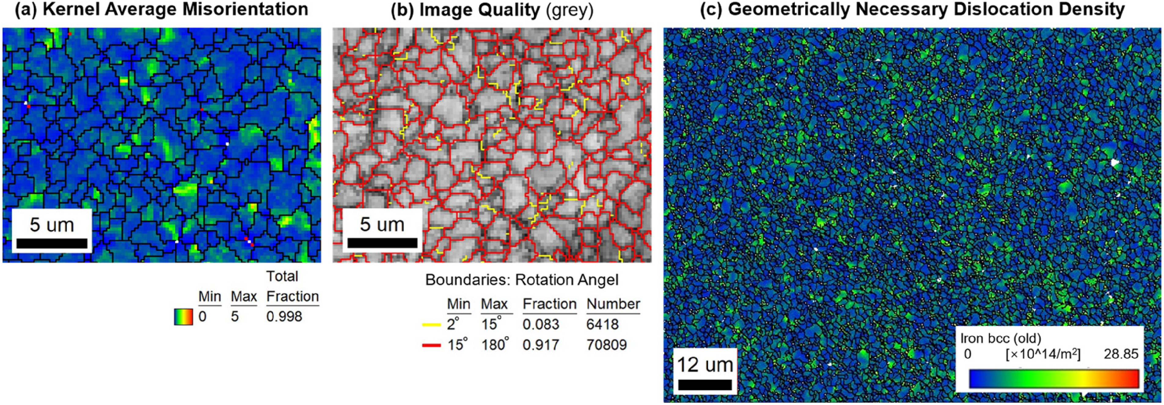
EBSD analysis for the WCZ of Trial I. (a) KAM map of the first neighbour rank; (b) IQ map for grain boundaries; (c) GND densities calculated by KAM.
Besides, the grain-boundary strengthening mechanism has already been investigated extensively, that is, the influence of grain size on the yield and flow behaviour of metals, and it could be clearly defined by the adherence to the Hall–Petch relationship,
29
as Equation (2):

The refined grain size and the high proportion of high-angle grain boundaries indicating the high density of GNDs microstructure in WCZ of Trial I resulted in a combined effect of grain-boundary and dislocation strengthening. 15 This effect enhanced the comprehensive performance of the as-welded joint and accounted for quasi-equal strength and toughness matched that of U75V BM.
The continuous cooling transformation (CCT) diagram of a material computed using JMatPro as a function of the elements is a useful tool for representing the phase transformations that may occur under various cooling rates. 30 The CCT diagram also provides information about the predicted hardness of different phases under different cooling conditions. 31
Figure 8 displays the CCT diagram of U75V rail steel, calculated using JMatPro, and schematic diagrams depicting microstructure evolution during the CDFW process. Additionally, the CCT diagram includes the simulated cooling curves of WCZ-0 and WPZ-0 (pertaining to Trial I), as shown in Figure 6(c) & (d), which were inserted for analysis. This diagram provides valuable information regarding the predicted hardness of U75V at varying cooling conditions. 32 The simulated cooling curve WPZ-0 of the investigated subzone had a peak temperature that exceeded Ac1 and ultimately fell into the martensite phase region, suggesting the potential transformation of undercooled austenite into high-hardness martensite within a specific cooling rate range. This finding agrees with the microstructural analysis and microhardness test results reported above. The material in this subzone transitioned from pearlite microstructure, as shown in Figure 8(b), to martensite and RA microstructure, as illustrated in Figure 8(c), accompanied by increased hardness. Despite falling into the martensitic phase region, the simulated cooling curve of WCZ-0 exhibited a throughout temperature lower than Ac1, leading to a phase that differed from the one obtained by undercooled austenite at the same cooling rate. The microstructure in this subzone, as presented in Figure 8(d), featuring high-density GNDs, did not exhibit typical martensitic morphology at similar cooling rates. Instead, it showed finer grains and a microhardness comparable to the BM, indicating the absence of austenite transformation. These findings prove that the high density GNDs microstructures were produced through DRX below Ac1 temperature.
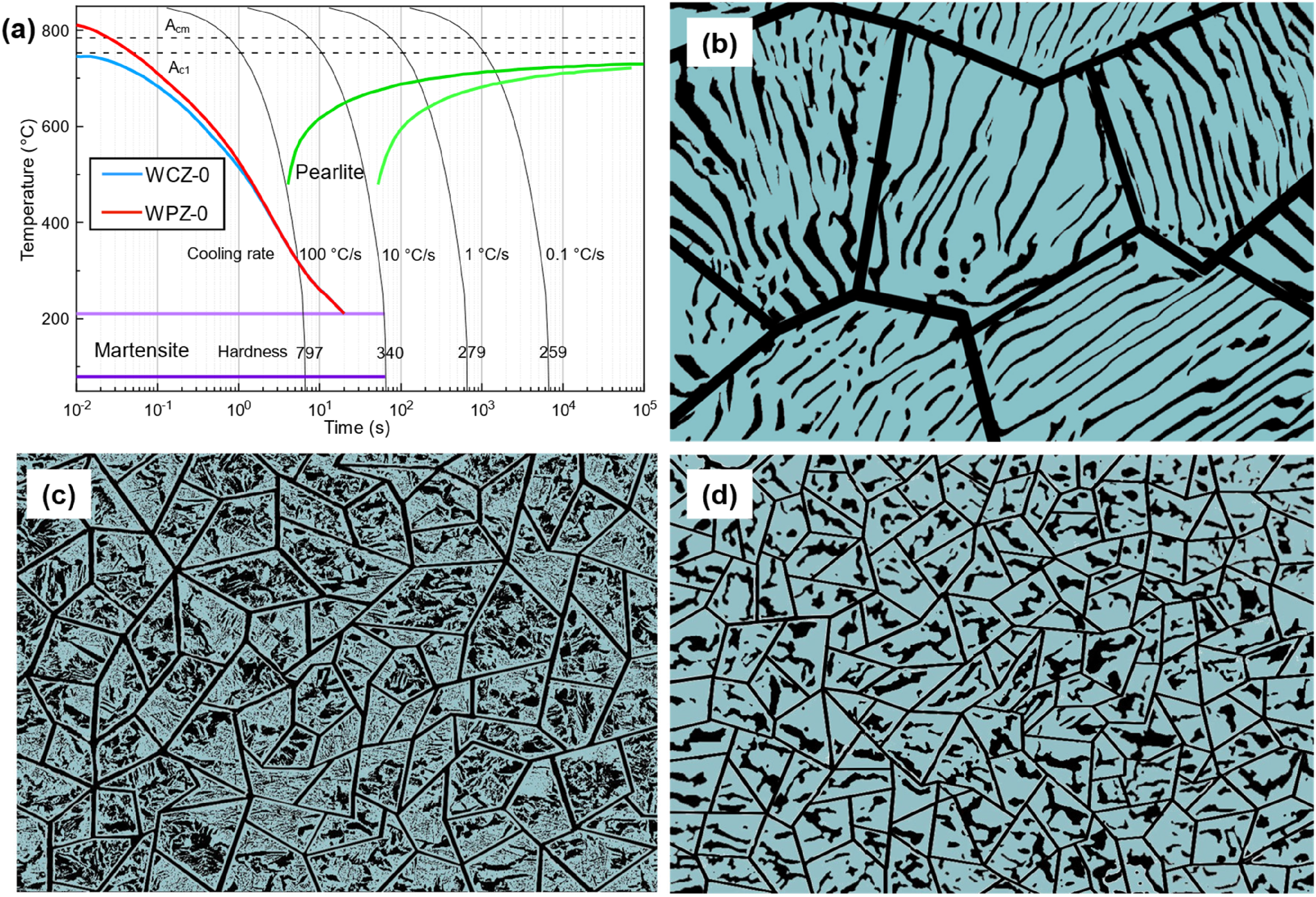
Calculated CCT diagram of U75V rail steel and the inserted simulation cooling curves of Trial I (a); schematic diagrams for microstructure evolution during CDFW process: (b) pearlite (U75V BM); (c) martensite and RA; (d) microstructures with high-density GNDs.
Conclusions
In summary, through appropriate process parameter combinations, U75V rail steel rods were successfully joined using CDFW, achieving a sound metallurgical bond in the welded joint without common welding defects such as slag inclusions and lack of fusion. When the joint was made at a spindle speed of 1000 r/min, a friction pressure of 50 MPa, a friction time of 4 s, an upsetting pressure of 150 MPa and an upsetting time of 4 s, the material experienced dynamic recrystallization below Ac1 temperature, resulting in a quasi-equal strength and toughness joint matching that of the U75V rail steel. Thus, a well-metallurgical bond welded joint could be achieved without sacrificing toughness. The conclusions are summarised as follows:
Friction welding below Ac1 temperature requires a set of strict welding process parameters combination, that is, appropriate spindle speed and axial pressure to generate opportune welding heat input and plastic deformation. Materials near the rod centre axis of the weld zone underwent dynamic recrystallization below Ac1 temperature, bringing about microstructures with high density geometrically necessary dislocations holding the combined effect of grain-boundary and dislocation strengthening, which enhances the comprehensive performance of the welded joint. Without post-welded heat treatment, the as-welded joint had sound mechanical properties of tensile strength (exceeding 90% of that of base metal), qualified impact toughness (KU2 ≥ 12.0 J), and the microhardness in the WCZ closely resembles that of the base metal.
Footnotes
Acknowledgements
We would like to thank Ying Wu and Chaoyu Han for their help in metallographic, Xueyang Guo and Guodong Liang for their help in welding experiments, and Xinghao Yan and Chengkai Qian for their help in the EBSD analysis.
Declaration of conflicting interests
The authors declared no potential conflicts of interest with respect to the research, authorship, and/or publication of this article.
Funding
The authors disclosed receipt of the following financial support for the research, authorship, and/or publication of this article: This research was funded by the National Natural Science Foundation of China under grant no.51775301 and no.51075231.