
Abstract
Cathode erosion is a serious problem in long hours of Tungsten Inert Gas (TIG) welding. The evolution of electrode end shape and corresponding arc behaviour was studied at different welding currents and cathode parameters. The results illustrate that slow erosion, shedding, and expansion are three typical erosion modes. Slow erosion is an inevitable mode, causing the arc root width (Ra) and arc diameter (Rb) to slowly increase by 2.1% and 2.6%, respectively. With the increasing welding current or the decreasing cone angle and diameter, Ra and Rb are increased in shedding mode by 6.3% and 1.0%, respectively. Expansion appears when the electrode end has a truncated cone shape, causing gradual decrease of 5.7% and 2.3% in Ra and Rb, respectively.
Introduction
High quality, high efficiency, and low cost are important directions for the development of modern manufacturing industry.1,2 Tungsten inert gas (TIG) welding is widely utilized in the welding production of thin-walled structural elements due to its advantages of stable welding process, high quality, and low cost. 3 The direct current electrode negative (DCEN) is generally applied in the TIG welding production of stainless steel pipes. The cathode (i.e., tungsten electrode) will be eroded at high temperature due to the arc heat, the bombardment of high-energy positive ions, and its own resistance heat. 4 The cathode erosion, which alters the end shape, will significantly affect the arc shape and final joint quality,5,6 causing low welding productivity and high costs. However, the replacement of the tungsten electrode is generally based on the experience of workers to avoid the unqualified joints caused by cathode erosion, which lacks accurate data support. Therefore, it is necessary to systematically study the phenomenon of cathode erosion and its effect on the arc behaviour to provide basic data and theoretical support for the standardisation of tungsten electrode replacement in TIG welding production of stainless steel pipes.
Most researchers focused on the studies of physical and chemical characteristics of the tungsten electrode and erosion amount. Tanaka et al. 7 found that the pure tungsten electrode showed the highest work function, followed by the W-ThO2 and W-La2O3 electrodes. By doping the rare earth oxide with a lower work function, the end temperature of the tungsten electrode was lower at the same welding parameters.8,9 The lower temperature at the electrode end is in favour of alleviating the detrimental effect of cathode erosion. However, the W-ThO2 electrode is widely applied in practical welding production due to its lower cost, easy arc initiation, and stable arc. Sillero et al. 10 observed that the end temperature of the W-ThO2 electrode increased with the increasing welding current. However, the end temperature (i.e. peak temperature) was not influenced by the electrode diameter and end shape, which affected the temperature distribution on the W-ThO2 electrode surface, as reported by Zhou and Heberlein. 11
Some scholars measured the mass loss of electrodes to evaluate the erosion amount. Matsuda et al. 12 found that the pure tungsten electrode exhibited the largest mass loss due to its highest work function. Casado et al. 13 found that a critical current intensity existed for each kind of electrode, at which the mass loss was the greatest. Sakura et al. 14 proposed that the erosion amount with Ar-N2 shielding gas was greater than that with pure Ar shielding gas. Ogawa et al. 15 also found that the end temperature was higher with the selection of pure He shielding gas, which caused more erosion amount than that using pure Ar shielding gas.
In terms of the mechanism of cathode erosion, the pure tungsten electrode was eroded in the form of evaporating and blowing off liquid droplets. However, the erosion mechanism of the electrode doped with rare earth oxides, such as W-ThO2, was the evaporation of the electrode. 16 Besides, Zhou and Heberlein 17 discovered that the evaporating thorium and tungsten would redeposit to the lower temperature region of the electrode during the welding process, which was consistent with the studies proposed by Matsuda et al. 18 , Zhukov et al., 19 and Liu et al. 20 It means that the erosion amount of the cathode cannot be completely characterised by the mass loss. In contrast, the change in the end shape can directly reflect the degree of cathode erosion and further influence the arc behaviour. However, most researchers evaluated the cathode erosion by measuring the mass loss. The evolution of the electrode end shape and its effect on the arc behaviour in the welding process has not been systematically studied.
In this study, by using a TIG arc ignition system, the characteristic parameters of the end shape and arc behaviour were determined and extracted with an image processing algorithm to investigate the influences of welding current, electrode cone angle, electrode end width, electrode extension length, and electrode diameter on cathode erosion. Furthermore, the evolution rules of end shape and its influence on arc behaviour at different welding parameters were also summarized during the long-term TIG welding process.
Experimental details
Experimental platform and procedure
As shown in Figure 1(a), the TIG arc ignition system was established to study the cathode erosion, which consisted of the welding system, the image acquisition system, and the electrical parameters system. The welding system included a TIG welding power source, a water-cooled copper plate, and a circulating water tank. The welding torch was situated perpendicularly to the copper plate, and the welding mode was DCEN. To avoid the deformation and melting of the copper plate, the water circulates underneath the plate to cool it down for arc stability. The image acquisition system mainly included two charge-coupled device (CCD) cameras equipped with a permeable narrowband filter with a wavelength of 950 nm and an ND1000 neutral density filter to capture electrode shape and arc shape, respectively. The electrical parameter acquisition system consisted of an ART 3106A data acquisition board and Hall sensors. Before the test, the copper plate was polished with sandpaper. The electrode was ground into different angles in the conical shape and different end widths in the truncated cone shape. Then it was assembled to the connector of the torch by means of the electrode holder, ceramic nozzle, and cap. The extension length was the distance from the electrode end to the ceramic nozzle, as shown in Figure 1(b).
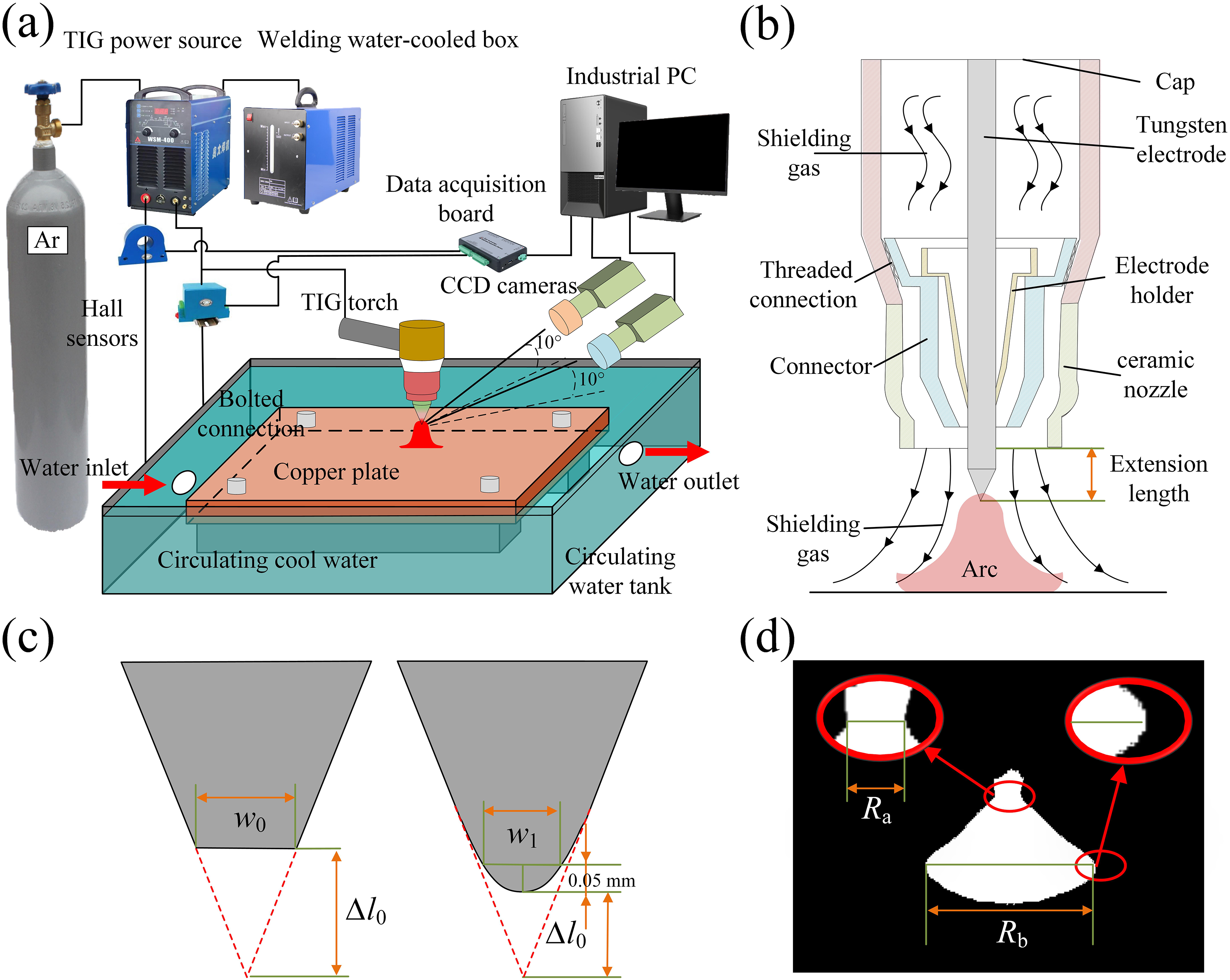
(a) Schematic diagram of cathode erosion experiment system, (b) cross-section view of TIG welding torch, definition of characteristic parameters of (c) tungsten electrode, and (d) arc.
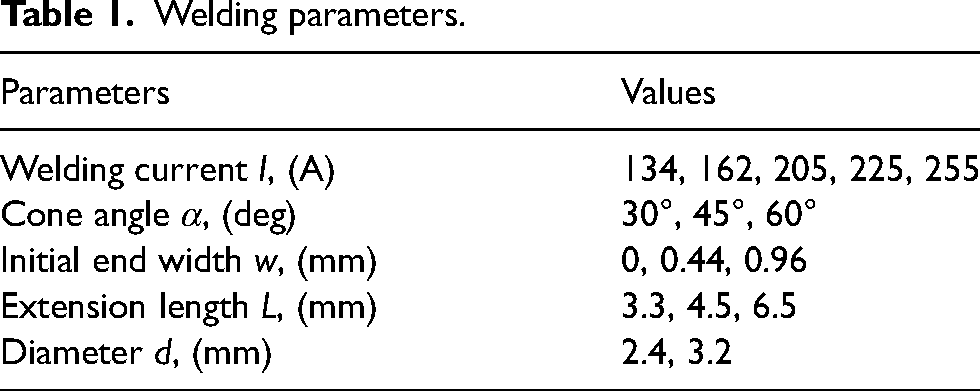
To study the effect of welding current and electrode shape on cathode erosion and arc behaviour, the welding parameters were determined based on preliminary experiments, as shown in Table 1. Besides, some parameters were kept unchanged. The thoriated electrode doped with 2% ThO2 was selected as the cathode with an electrode height of 2.5 mm. The shielding gas applied was pure Ar with a flowing rate of 10 L/min. The electrode shape and arc behaviour were measured during the erosion process for 480 min.
Welding parameters.
Analysis methods
In TIG welding, the erosion is the most severe at the end of the electrode, showing either the truncated cone shape or elliptical shape, which will be further discussed in the next section. To distinguish the shape and erosion state, feature parameters in the x and y directions were defined, as shown in Figure 1(c). w0 was the end width of the electrode with a truncated cone shape. w1 was the transverse width of the position 0.05 mm from the end and defined as the fixed-length width, which reflected the sharpness degree of the electrode with an elliptical shape. The axial shortening length (l0) was the most important variable to characterise the erosion amount due to its direct reflection on the erosion state. The arc root width (Ra) and arc diameter (Rb), which were the minimum and maximum widths of the arc, were also defined to characterise the arc shape, as shown in Figure 1(d). The parameters in the image were accurately extracted via the image processing algorithms. The 100 images in total were captured at intervals of 1000 µs and the characteristic parameters of electrode and arc were extracted. The average values for the 100 images were calculated to obtain the characteristic parameters. Some insights in relation to the arc behavior could also be inferred through examining the arc voltage.
Results and discussion
Influence of welding parameters on cathode erosion
Figure 2 shows the cathode erosion processes at different welding currents. All the electrode ends gradually evolved into the elliptical shape over the welding time. With the current increasing to 255 A, the shedding occurred between the 440th minute and the 441st minute and the end still retained the characterisation of elliptical shape, as shown in Figure 2(e). The axial shortening length of the electrode working for 480 min increased nonlinearly with the increased welding current, as shown in Figure 2(f). Compared with the electrode at 134 A, the erosion amount at 255 A increased by 436.6%. With a higher welding current, both the resistance heat of the electrode and the heat transferred from the arc increased, accelerating the cathode erosion. Under the prerequisite of weld penetration, the welding current should be minimised to reduce the cathode erosion.
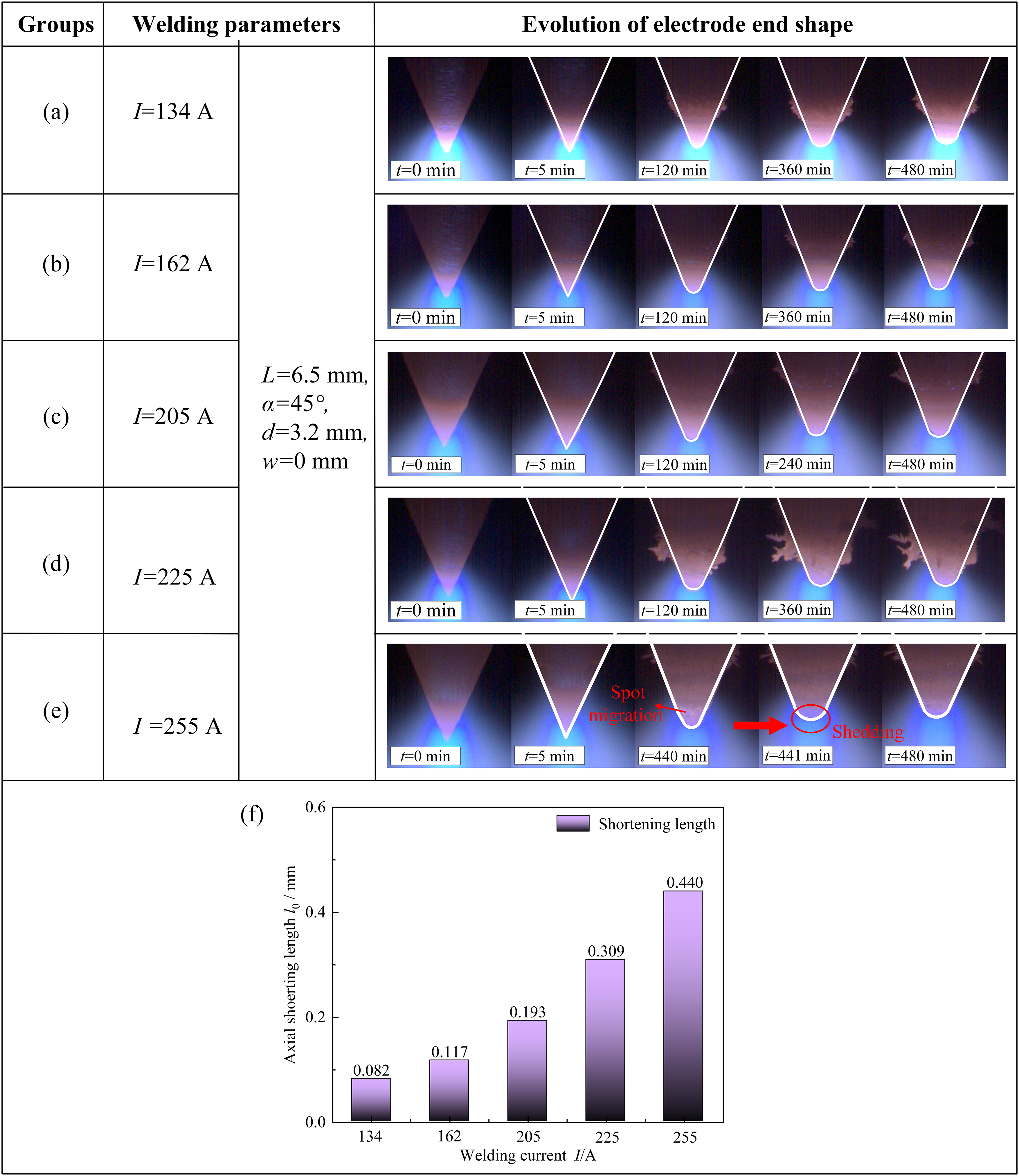
Evolution processes of the electrodes at different welding currents: (a) I = 134 A, (b) I = 162 A, (c) I = 205 A, (d) I = 225 A, (d) I = 255 A, and (f) axial shortening length.
Figure 3(a)–(c) shows the effect of cone angle on the evolution process of the electrode. The shedding and expansion were observed, with the end mainly showed the truncated cone shape for the electrode at the cone angle of 30°. In contrast, the ends gradually evolved into the elliptical shape for the angles of 45° and 60°. The increasing cone angle decreased the erosion amount, as presented in Figure 3(f). Compared with the electrode at the angle of 30°, the erosion amount at angles of 45° and 60° decreased by 70.1% and 82.0%, respectively.
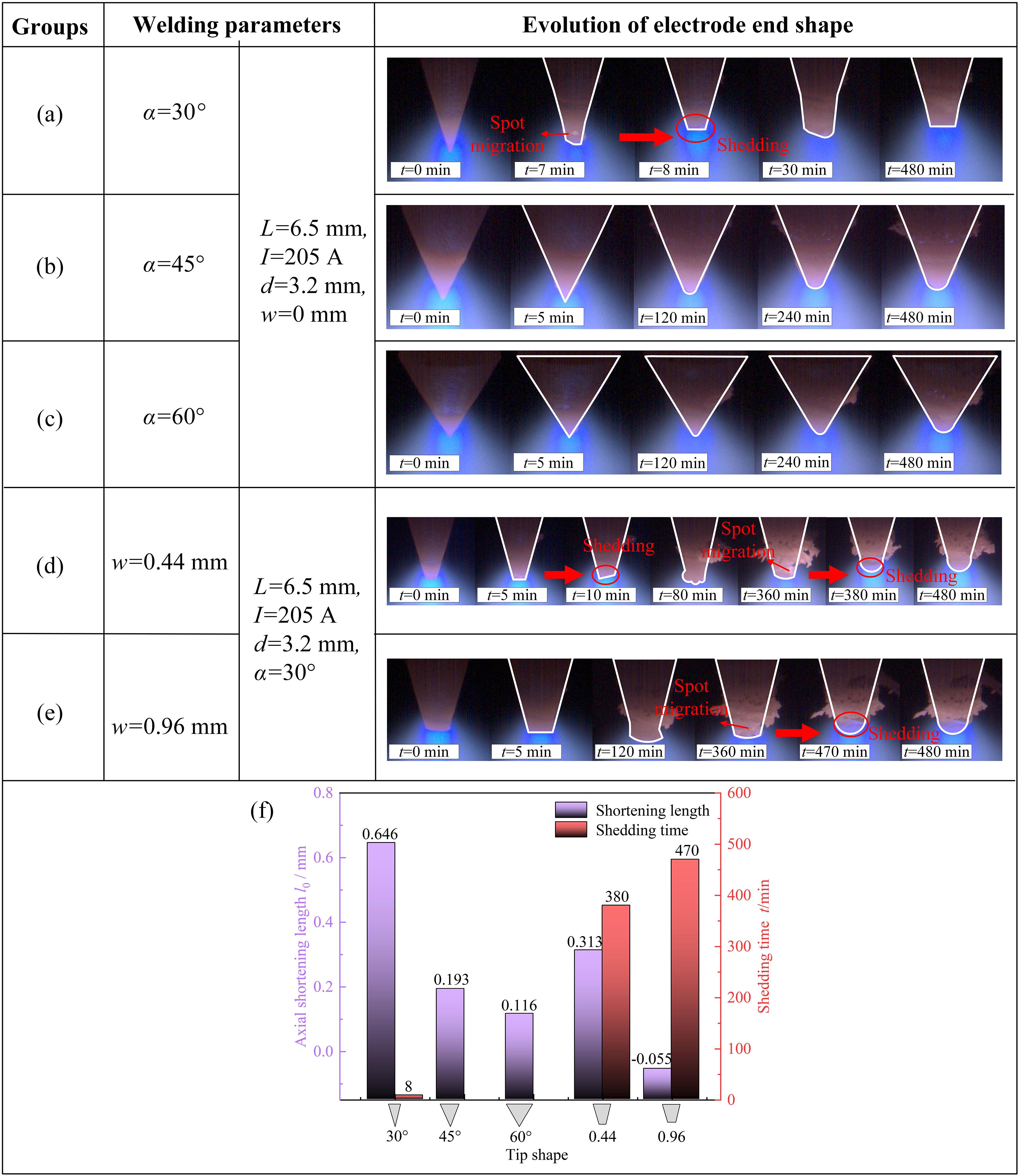
Evolution processes of the electrodes with different end shapes: (a) α = 30°, w = 0 mm, (b) α = 45°, w = 0 mm, (c) α = 60°, w = 0 mm (d) α = 30°, w = 0.44 mm, (e) α = 30°, w = 0.96 mm, and (f) axial shortening length and shedding time.
The shedding phenomenon was observed for all electrodes with the cone angle of 30° at different end widths. As the end width increased, the time for the occurrence of shedding was delayed and the erosion amount was decreased, which was beneficial to prolonging the working time and improving the production efficiency.
Figure 4(a)–(c) shows the evolution processes of the electrodes at different extension lengths. The shortened extension length caused a slight decrease in erosion amount and a delay in shedding time, as shown in Figure 4(g). To reduce the erosion amount, the extension length should be shortened as much as possible. However, it should not be too small to avoid hindering the observation of the welding pool.
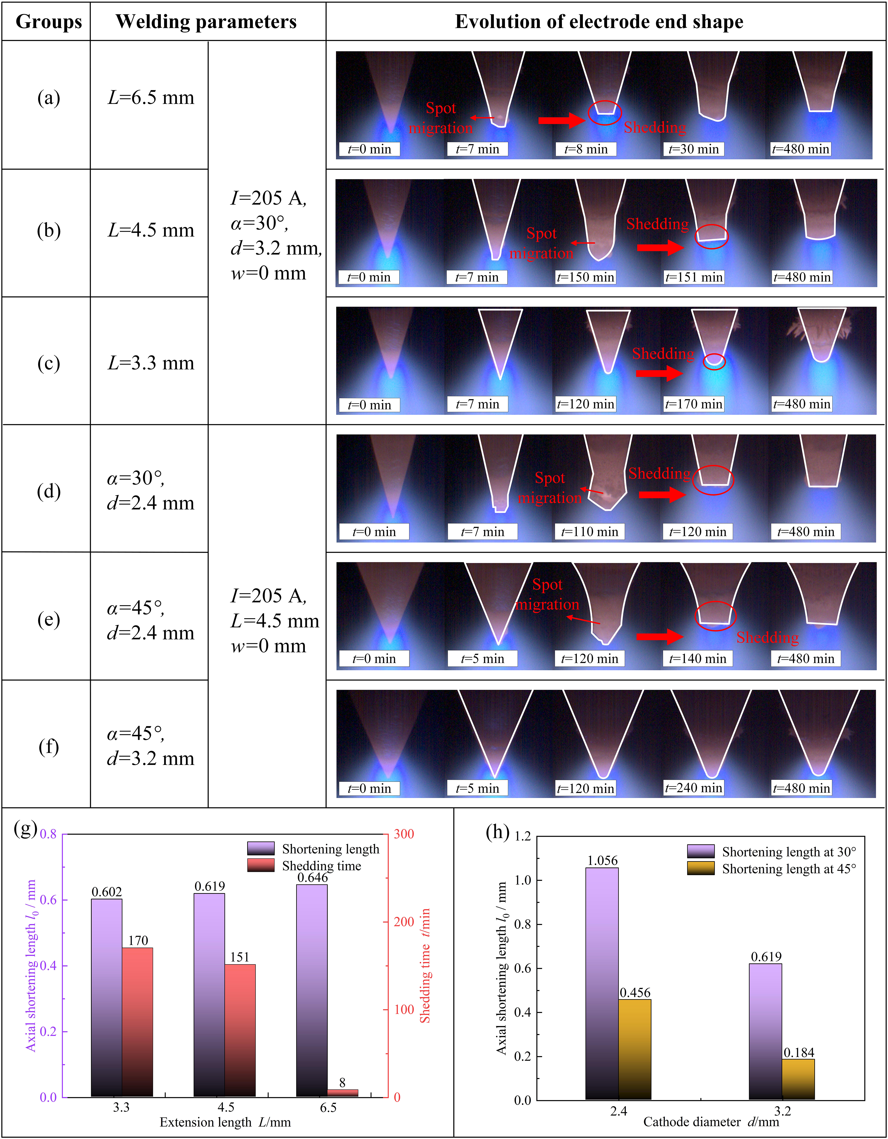
Evolution processes of the electrodes at different extension lengths and diameters: (a) L = 6.5 mm, (b) L = 4.5 mm, (c) L = 3.3 mm, (d) α = 30°, d = 2.4 mm, (e) α = 45°, d = 2.4 mm, (f) α = 45°, d = 3.2 mm, axial shortening length and shedding time at different (g) extension lengths, and (h) cathode diameters.
To investigate the effect of electrode diameter on the erosion process, the evolution processes of the electrodes with diameters of 2.4 and 3.2 mm were analysed. At the angle of 30°, the erosion amount of the electrode increased by 70.6% with the diameter decreasing from 3.2 to 2.4 mm, as shown in Figure 4(b), (d), and (h). The erosion amount of the electrode increased by 147.8% with the decreasing diameter at the angle of 45°, as presented in Figure 4(e), (f), and (h). The larger diameter of the electrode is beneficial to weakening cathode erosion.
At a constant welding current, the resistance heat was influenced by the electrode shape. With the decrease of cone angle, diameter, and end width, the resistance heat of the electrode increased, promoting the cathode erosion. In contrast, the increasing extension length increased the resistance heat and weakened the cooling effect by increasing the distance from the end to the water-cooled electrode holder. A higher resistance heat caused a smaller temperature gradient on the electrode surface, leading to a larger high-temperature area and more erosion amount.
Evolution rules of end shape during the process of cathode erosion
Based on the above analysis, the cathode erosion was summarised as three modes, which consisted of slow erosion, shedding, and expansion, as shown in Figure 5. The electrode end shape was characterised either by an elliptical shape featuring a certain curvature or by a truncated cone shape with a slight burr or minimal curvature.
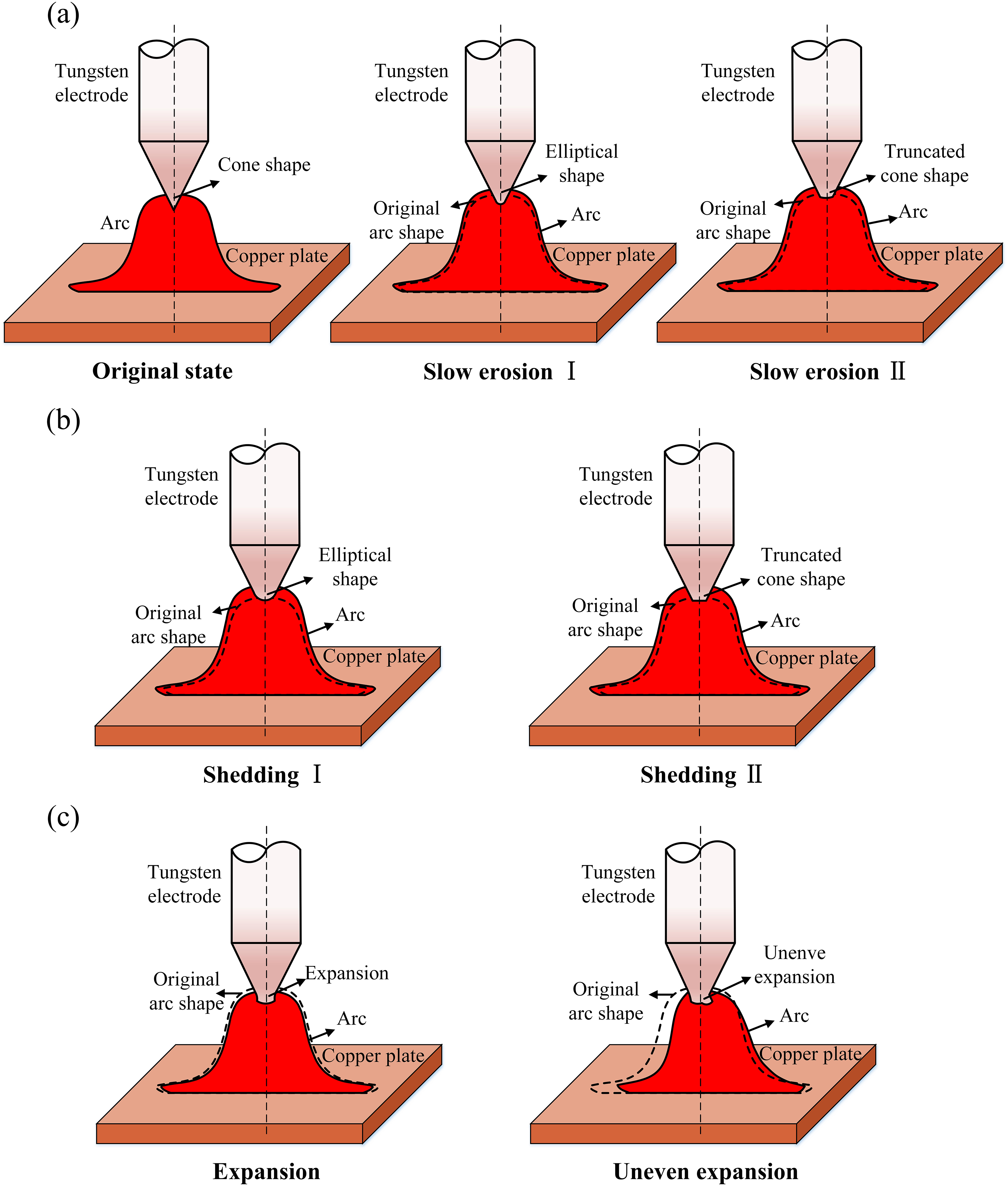
Erosion modes and end shapes; (a) original state and slow erosion mode, (b) shedding mode, and (c) expansion mode.
During the welding process, the slow evaporation of the tungsten electrode was inevitable and defined as slow erosion. With the decrease of welding current and electrode extension length and the increase of cone angle and diameter, the end tended to be ellipsoid slowly, which was defined as slow erosion I mode. Once the electrode end expanded, the end would evolve to the truncated cone shape slowly, which was slow erosion II mode. From the perspective of welding parameters, as the initial end shape was truncated cone shape, the expansion was bound to occur in the erosion process. When the initial shape was conical, the expansion was easier to be observed at the larger extension length, smaller cone angle, and diameter.
The migration of the cathode spot was easier to occur at higher welding currents, greater electrode extension lengths, smaller cone angles and diameters, which will be discussed in arc behaviour changes in group A section. The electrode was locally melted at the high temperature of the cathode spot. A piece of tungsten may fall from the end to the copper plate, causing the phenomenon of shedding. The end shape after shedding could be ellipsoid or truncated cone shapes, which were defined as shedding I and II mode, respectively. The shedding after slow erosion invariably displayed the characterisation of shedding I mode. With a small diameter and cone angle, the shedding occurring at the early stage was characterised as shedding II mode.
The expansion generally occurred due to higher temperature when the end was truncated cone shape initially or showed truncated cone shape after shedding, which was manifested as lateral thickening and axial elongation. However, the expansion may be uneven, showing an inconsistent expansion on both sides, as shown in Figure 5(c). In general, the erosion process at different welding parameters was a combination of different erosion modes. The end shape and its effect on the arc behaviour also varied at different welding parameters.
Influence of erosion mode and end shape on arc behaviour
To systematically investigate the influence of erosion mode and end shape on arc behaviour, three typical groups were defined based on the erosion characterisation. The erosion process with the conical electrode at the angle of 30° was defined as group A, as shown in Figure 3(a). The erosion process with the conical electrode at angles of 45° and 60°, was defined as group B, as shown in Figures 2(e), 3(b), and 3(c). Among them, Figure 2(e) was selected to analyse due to its typical erosion characterisation. The erosion process of the electrode with the truncated cone shape was defined as group C, as presented in Figure 3(d). Figure 6 shows the corresponding arc shapes of groups A, B, and C, respectively.
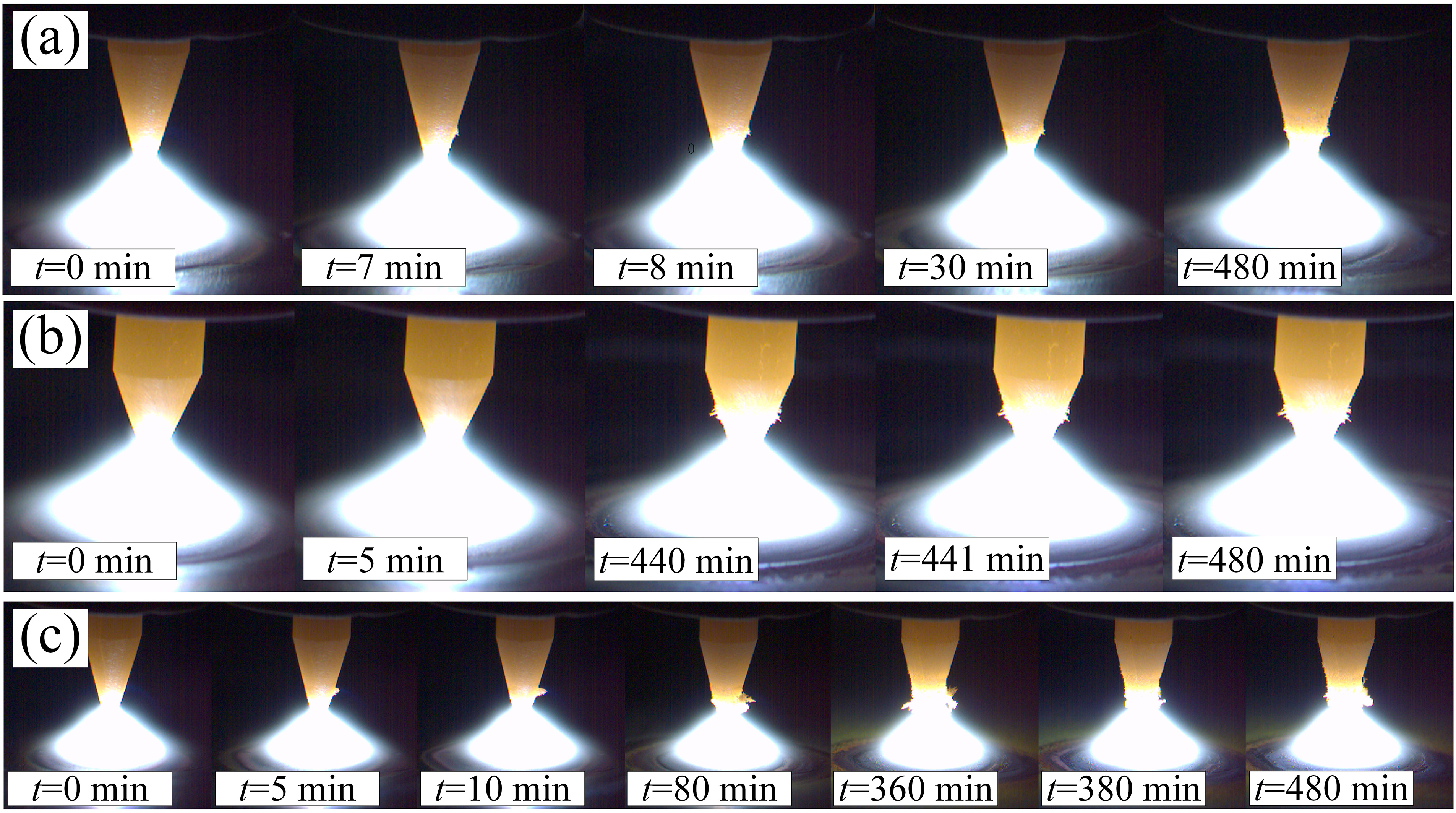
Evolution of arc shape in groups (a) A, (b) B, and (c) C.
Arc behaviour changes in group A
Based on the changes in characteristic parameters of the tungsten electrode and arc introduced in analysis methods section, the erosion process of group A was divided into four stages: instability (I), severe erosion (II), expansion (III), and slow erosion (IV), as shown in Figure 7(a)–(c).
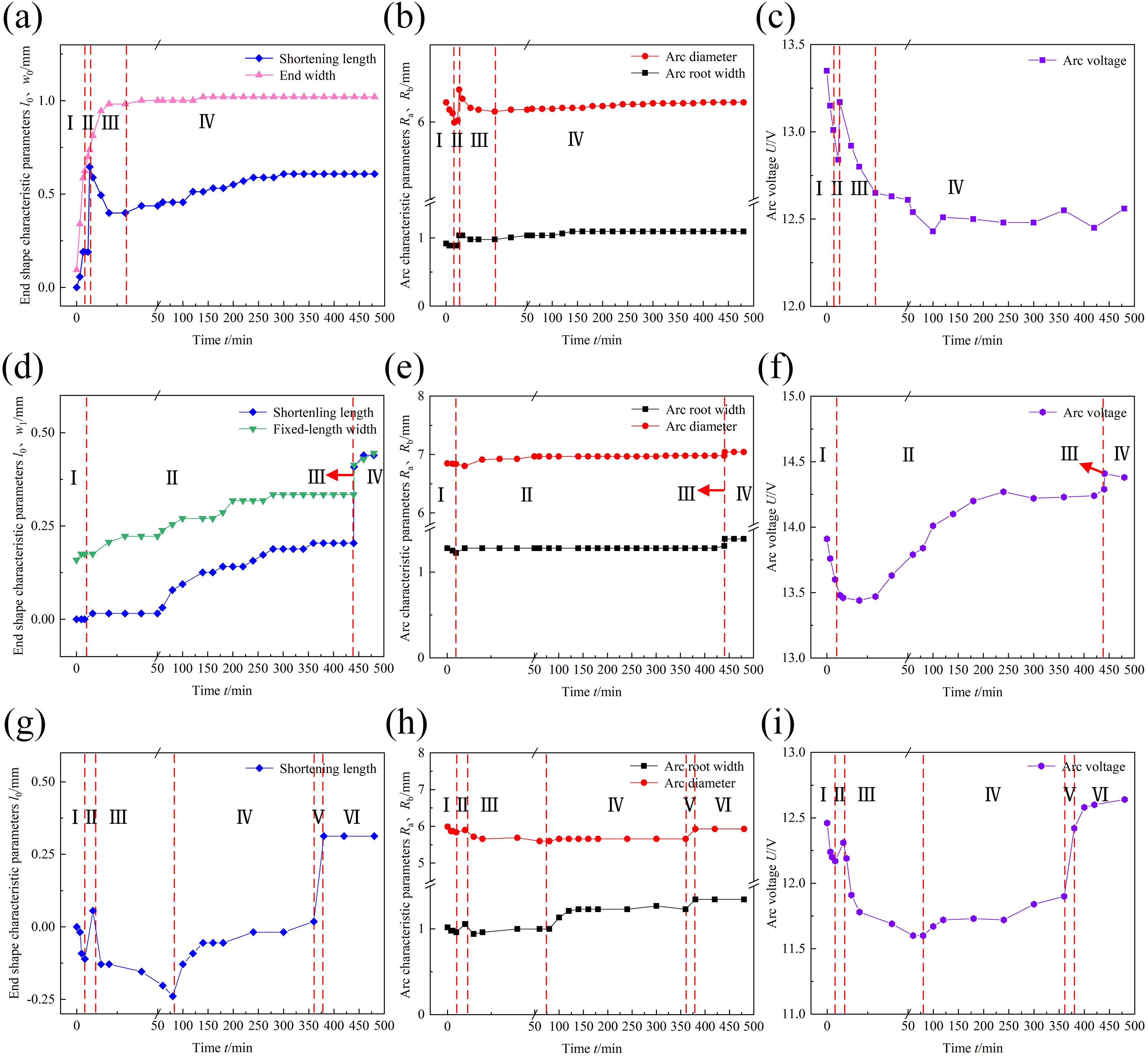
Characteristic parameters of tungsten electrode in the group: (a) A, (d) B, and (g) C, arc shape in the group: (b) A, (e) B, and (h) C, and arc voltage in the group: (c) A, (f) B, and (i) C.
At stage I (from the 0th to the 7th minute), both the Ra and Rb showed a decreasing tendency, as shown in Figure 7(b). However, the variation of the electrode end was small, as presented in Figure 7(a). The erosion characteristics at the stage of instability would be further discussed in group B, which exhibited more representative feature.
Stage II (the 8th minute) represented a transient stage due to instantaneous shedding at the end. After shedding, the extension length decreased significantly. The slope of the axial shortening length curve was equivalent to the change of erosion amount per unit time and used to evaluate the erosion rate at this stage. The erosion rate at stage II was the highest with the greatest slope, as shown in Figure 7(a). The Ra, Rb, and arc voltage increased steeply, which were typical features of shedding, as shown in Figure 7(b) and (c). Compared to the beginning of the stage, the Ra and Rb at the end of the stage increased by 16.7% and 3.4%, respectively. Due to the greater evaporation rate of ThO2, a ThO2-poor area was observed by Zhou et al. 21 at the electrode end. The cathode spot was usually concentrated at the rare earth oxides, such as ThO2. 22 Therefore, the cathode spots moved upwards to find the ThO2-enriched regions. A brighter spot in Figure 3(a), which was the cathode spot, was observed at the end of the 7th minute before shedding. The temperature of the cathode spot was higher than the melting point of the cathode material. 23 The area where the cathode spot was concentrated was melted.
In group A, the electrode end transformed into the truncated cone shape after shedding, showing the characterisation of shedding II mode. Then the electrode end tended to expand (from the 8th to the 30th minute), as shown in Figure 3(a). This created a compressing effect on the arc, resulting in the decrease of Ra, Rb, and arc voltage, as shown in Figure 7(b) and (c).
After expansion, the erosion showed the characterisation of slow erosion II mode over a long period (from the 30th to the 480th minute). The characteristic parameters of the electrode and arc increased slowly, as shown in Figure 7(a)–(c). During the slow erosion II, the end transformed into the truncated cone shape, increasing the electrode height. The increase of electrode height led to the upward movement of the arc attachment position, resulting in the increase of arc voltage, Ra and Rb.
Arc behaviour changes in group B
The erosion process of group B was also divided into four stages: instability (I), slow erosion (II), severe erosion (III), and slow erosion (IV), as shown in Figure 7(d)–(f).
At stage I (from the 0th to the 5th minute), the axial shortening length and fixed-length width hardly changed, as shown in Figure 7(d). While the Ra and Rb decreased by 4.3% and 0.2%, respectively, as shown in Figure 7(e). The arc voltage also showed a decreasing tendency in Figure 7(f), which consisted of: cathode voltage drop, arc column voltage drop, and anode voltage drop. With the welding current and anode maintaining stability, the change in arc voltage was mainly influenced by the cathode voltage drop.
24
The reduction of cathode pressure drop represented the improvement of electron emission capability.
22
According to the empirical equation of Richardson-Dushman,
25
the rising temperature will increase the thermionic current density, as shown in Equation (1):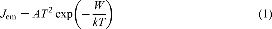
Following the stage of instability, the slow erosion maintained a very long time, as presented in Figure 7(d)–(f). The changes of electrode and arc were similar to the slow erosion stage of group A. However, the end evolved into an elliptical shape in the form of slow erosion I mode, which was different from group A.
Subsequently, a brighter spot was observed at the end after slow erosion, as shown at the 440th minute in Figure 2(e). It meant that the condition for cathode spot migration was reached. As a result, the electrode end was shedded into the elliptical shape with shedding I mode. The slope of this stage was the greatest, which represented that its erosion rate was the highest in group B, as shown in Figure 7(d). After shedding, the electrode showed the characterisation of slow erosion again, which was the same as stage II. However, a little change was observed for the characteristic parameters of the electrode and arc due to the short observation time.
Arc behaviour changes in group C
The erosion process of group C was divided into the stages of instability (I), severe erosion (II), expansion (III), slow erosion (IV), severe erosion (V), and slow erosion (VI). Only the axial shortening length was extracted in this group due to its complicated evolution.
The arc behaviour showed the decreasing tendency at the stage of instability, which was also aggravated by the expansion, as shown in Figures 3(d) and 7(g)–(i). As the electrode angle was small, the electrode shed early. However, the shedding amount was small as a result of the larger end width. Post-shedding, the electrode expanded again, which was more serious than group A, as shown in Figure 3(a) and (d). After a long time of slow erosion, the migration of cathode spots caused the occurrence of shedding I. Then, the electrode was slowly eroded again.
Discussion
The varied erosion modes and their corresponding end shapes influenced the arc behaviour differently. The erosion process consisted of various erosion modes at different welding parameters. Slow erosion led to a gradual increase in arc characteristic parameters. Shedding resulted in a transient increase in arc characteristic parameters. While expansion caused a decrease in arc characteristic parameters. Throughout the entire erosion process, the cathode erosion led to an increase in the Ra and Rb. For instance, compared to the beginning of stage II, the Ra and Rb at the end of the final stage in group B increased by 13.3% and 3.5%, respectively. It was also evident that the cathode erosion had a greater influence on Ra than Rb.
The three groups (i.e. A, B, and C) that were defined above represented all of the experiments in this paper. The cone angle in group B was larger than that in group A, which was beneficial to reducing cathode erosion. However, the erosion process for the electrode with the angle of 30° and the extension length of 3.3 mm belonged to group B due to reduced resistance heat and enhanced cooling effect. The truncated cone shape in group C could also weaken the cathode erosion, compared to the conical shape in group A. As the end width became larger, the erosion could avoid the shedding at the early stage for the electrode at the angle of 30°, as shown in Figure 3(e).
In the TIG welding process, changes in electrode end shape due to cathode erosion affected the arc behaviour. The variation of the arc further affected the arc pressure and heat distribution, thereby influencing the weld appearance, necessitating further experimental research.
Conclusions
In this paper, a TIG arc ignition system was established to investigate the effects of different welding parameters on cathode erosion. Besides, the evolution of the electrode end shape and its influence on the arc behaviour during the erosion process were also elaborated.
The following conclusions can be drawn from this study:
The modes of cathode erosion were divided into three types: slow erosion, shedding, and expansion. The cathode end mainly showed the elliptical shape or the truncated cone shape. For the conical electrode with large angle and diameter (i.e. group B), the erosion process was relatively simple without the expansion modes. For the electrode with small angle conical shape or a truncated cone shape (i.e. groups A and C), they entered the stage of severe erosion immediately after the stage of instability, followed by the expansion stage and the final slow erosion stage. Slow erosion caused the arc root width (Ra) and arc diameter (Rb) to slowly increase by 2.1% and 2.6%, respectively. Shedding resulted in a rapid increase of 6.3% and 1.0% in Ra and Rb, respectively. Expansion caused Ra and Rb to decrease by 5.7% and 2.3%, respectively. For the whole erosion process, the cathode erosion could lead to an increase in Ra and Rb by 13.3% and 3.5%, respectively. However, it had a greater influence on Ra than on Rb. To reduce the erosion amount and delay the shedding time, the cone angle should be ground at angles of 45°–60°. Additionally, the end should be machined to a specific width. In addition, it was necessary to reduce the extension length and increase the diameter while ensuring adherence to welding conditions.
Footnotes
Declaration of conflicting interests
The authors declared no potential conflicts of interest with respect to the research, authorship, and/or publication of this article.
Funding
The authors disclosed receipt of the following financial support for the research, authorship, and/or publication of this article: This work was supported by the National Natural Science Foundation of China [Grant number: U21A20129, 51575317].