
Abstract
A technique for estimating the sound absorption of materials under oblique incidence plane wave and diffuse field excitations is proposed. It requires a mobile loudspeaker and a pair of fixed microphones above a layer of absorbing material. Starting from sound pressure measurements made above the material surface for multiple source positions and by inverting Allard’s propagation model, the proposed method allows for the identification of two effective (or equivalent) parameters, namely, the complex effective density and the complex wave number. Obtaining these parameters makes it possible to estimate the sound absorption coefficient for a plane wave with any angle of incidence or under a diffuse acoustic field by summation over the angles. The results are compared to theoretical values calculated using the Johnson-Champoux-Allard model and to reference measurements obtained using an impedance tube, a small cabin, a large reverberant room, and a sound field synthesis method. One of the limitations of this method lies in the assumptions associated with the Allard model to describe the sound field above the material (assumed to be isotropic, homogeneous, of constant thickness, and to behave like an equivalent fluid). The main advantages are (1) that the sound absorption coefficient can be estimated under oblique incidence plane wave and diffuse acoustic field with values that are always in a physical range (between 0 and 1), and (2) that samples of the order of the square meter without specific preparation can be tested which reduces the constraints associated with impedance tube or reverberant room measurements.
Introduction
A precise knowledge of the properties of sound-absorbing materials is essential to achieve efficient noise control and reduction to improve the quality of the sound environment. Several sectors, such as construction and transport, must comply with noise regulations. Still, noise control has a broader scope and involves cities, workplaces, and transportation means given the health impacts of noise at work and environmental noise.1,2 Two standardized methods are followed to measure the properties of sound-absorbing materials, and both were initially proposed nearly a century ago.3–9 The first is the impedance tube method10–13 and the second is the reverberation chamber method.14,15
Regarding the impedance tube, many improvements have been proposed to the early twentieth-century standing wave tube apparatus. 3 One-, 16 two-, 17 three- 18 and four-microphone 19 methods were developed in the last 40 years and are now included in standards.11–13 The obtained values for the sound absorption coefficient are usually within a physical range, between zero and unity. The method also requires a simple setup (a circular or square cross-section tube, at least one microphone and a loudspeaker). However, the impedance tube method is limited to normal or grazing incidence and up to a frequency that is restricted by the diameter of the tube. Results are obtained on samples that must be cut out from a large sample and may not represent the material’s properties given the sample size and the possible cutting and mounting effects.
On its side, the reverberation chamber method has evolved little since its proposal by Sabine. 20 It provides a diffuse field absorption coefficient, which corresponds to an average value over all incidence angles (see ASTM C42314 or ISO35415 standards). The reverberant chamber method requires extensive and costly measurement infrastructures and provides measurement results corresponding to a material’s behavior in a given test room. Unfortunately, standards require a minimum room volume, but no specific dimensions for the reverberation chamber are defined (variable geometrical parameters). Ultimately, the material’s size and mounting conditions also influence the estimated absorption such that, in general, significant inter-laboratory variations of estimated absorption coefficients have been observed.21,22 Moreover, a sound absorption coefficient larger than unity can be obtained.
The limitations of these two standardized methods have led to the development of various approaches for estimating sound absorption or sound impedance under normal, oblique, and random incidence. In addition, evaluating the performance of acoustic materials from an angle-dependent point of view is critical in a wide range of acoustics-related problems.
Room methods for measuring the sound absorption of materials under diffuse field conditions have been proposed, such as the use of small reverberation rooms (also called “alpha” cabins) 23 or ensemble averaging in any large rooms or reverberant rooms with pressure-velocity sensors24,25 or microphones. 26 Apart from room-based methods, approaches to estimating sound absorption under variable incidence can be broadly classified into two families: (1) The use of a single source and several receivers or a microphone array, and (2) the use of several sources and a microphone pair. The two-microphone based techniques, geometrical and measurement errors, limitations, and possible extension to in situ measurement are summarized in a series of four articles by Waddington and Orlowski27–30 and also by Brandão et al. 31 Most approaches include an anechoic environment, a single acoustic source, and a pair of microphones32,33 or a pressure velocity sensor. 34 Regarding multipoint microphone measurements, different arrangements were evaluated. A linear microphone array35,36 or a moving pair of microphones 37 with adequate post-processing were suggested. A double-layer microphone array was proposed in 38 to estimate sound impedance and absorption of porous material samples in an anechoic room and an ordinary room, with results that remained consistent when sample sizes and incidence angles were varied. Dragonetti et al. 39 performed a theoretical and experimental comparison between the plane and spherical reflection coefficient for different types of porous materials backed by a rigid surface. A single sound source and a linear array of 32 microphones were used, and the analysis followed the methods described in.32,37 Using the microphone array, Allard et al.’s model 40 and an optimization method, these authors were able to identify the material’s non-acoustic parameters (complex density and complex wavenumber).
Spherical or hemispherical microphone arrays and a spherical harmonic decomposition of the incident and reflected sound field were considered to estimate surface impedance, reflection and absorption coefficients under point source excitation in laboratory and in situ conditions.41,42 Nolan 43 proposed a method for measuring the angle-dependent absorption coefficient. A sound pressure field measured over a three-dimensional volume is decomposed into plane-wave components using a wave number transform, and the incident and reflected sound powers are calculated over two hemispheres (representing the incident and reflected wave fields). The method was validated in a classroom using a robotic arm and a single sound source, and a good agreement was found at most angles of incidence with calculations made using a transfer matrix method calculation.
While using a single sound source does not allow to control the incident sound pressure field, a loudspeaker array offers the possibility to generate a plane wave with a given incidence angle or a diffuse acoustic field. The application of sound field reproduction methods to acoustic material characterization was first proposed for the case of a normally incident plane wave to estimate the surface impedance and sound absorption, 44 and under a diffuse acoustic field excitation to evaluate the sound absorption.45,46 A single loudspeaker was moved at discrete positions above the material to define a virtual array at a post-processing step in Robin et al.,45,46 and the sound absorption coefficient was estimated under a synthesized diffuse acoustic field (the sound field is virtually achieved at a post-processing step, whence the term synthesized). Dupont et al.47,48 extended previous works, by using a 64-loudspeaker array to estimate the surface impedance and the sound absorption under plane waves with variable incidence angle, 47 and the diffuse field sound absorption coefficient was derived following Paris formula using angle-dependent sound absorption coefficients. 48 In Dupont et al.,47,48 the sound field was reproduced using a physical loudspeaker array. In all studies using physical or virtual loudspeaker arrays, the two-microphone technique was used to estimate the reflection coefficient, the surface impedance, or the sound absorption coefficient. In our previous work using the virtual source array approach45,46 (referred to as the Sound Field Synthesis, SFS, approach in this article), the sound field above the absorbing material was described using a simple image source model. Since this model is known to fail at low frequencies, the sound absorption provided by the SFS approach was not found to be reliable below 400 Hz. The main research question that triggered the present work was to improve the low-frequency absorption results of the SFS approach and reduce the associated experimental uncertainties, still in the paradigm of a virtual source array to create multiple incidence excitation.
Using a motorized test bench developed for this project, a characterization approach is proposed, which consists of inverting the Allard et al.’s propagation model
40
using sound pressure measurements made above a material surface for multiple source positions, and extracting the material properties (the complex wave number
The fundamental equations of the problem considered are first recalled in the ’Fundamental concepts’ Section. The reference methods, which include standardized measurements, the equivalent fluid model, and the SFS method are then described in the “Reference methods” Section. The proposed method based on Allard’s model inversion is detailed in the next section. The experimental details of the proposed approach are described in the “Experimental methods” Section and the results of the measurements are provided in the “Results” Section. A general discussion regarding reference methods and the proposed method is detailed in a specific section, followed by a conclusive Section.
Fundamental concepts
The general problem consists of an acoustic plane wave incident on a planar, homogeneous, isotropic, infinite lateral size layer of absorbing material. In this work, the absorbing material is modeled as an equivalent fluid. The incident acoustic wave is characterized by its angle of incidence


where

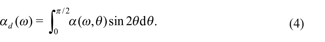
The diffuse field absorption coefficient
The absorption properties
where
where
Reference methods
In this work, the absorption results provided by the proposed inversion approach are compared to two standardized methods (impedance tube and reverberation chamber measurements), small cabin measurements, as well as the Sound Field Synthesis approach,46,51 which has conceptual connections with the proposed inversion method. The experimental results are compared to the Johnson-Champoux-Allard and Atalla model predictions. 52 These approaches are briefly recalled in the following sections.
Impedance tube
An impedance tube can be used to measure a material sample’s normal incidence sound absorption coefficient (see Figure 1). The experimental procedure is described in the standards ISO10534-212 and ASTM E1050-19.
13
A small sample is placed within a tube, housing a loudspeaker and two microphones positioned in front of the sample. Excitation is generated by a loudspeaker at one end of the tube (left-hand side in Figure 1), and the tested sample is placed at the opposite end and backed by a rigid wall. Two microphones, A and B in Figure 1, are placed between the loudspeaker and the sample. The frequency range is defined by the cross-sectional diameter of the tube
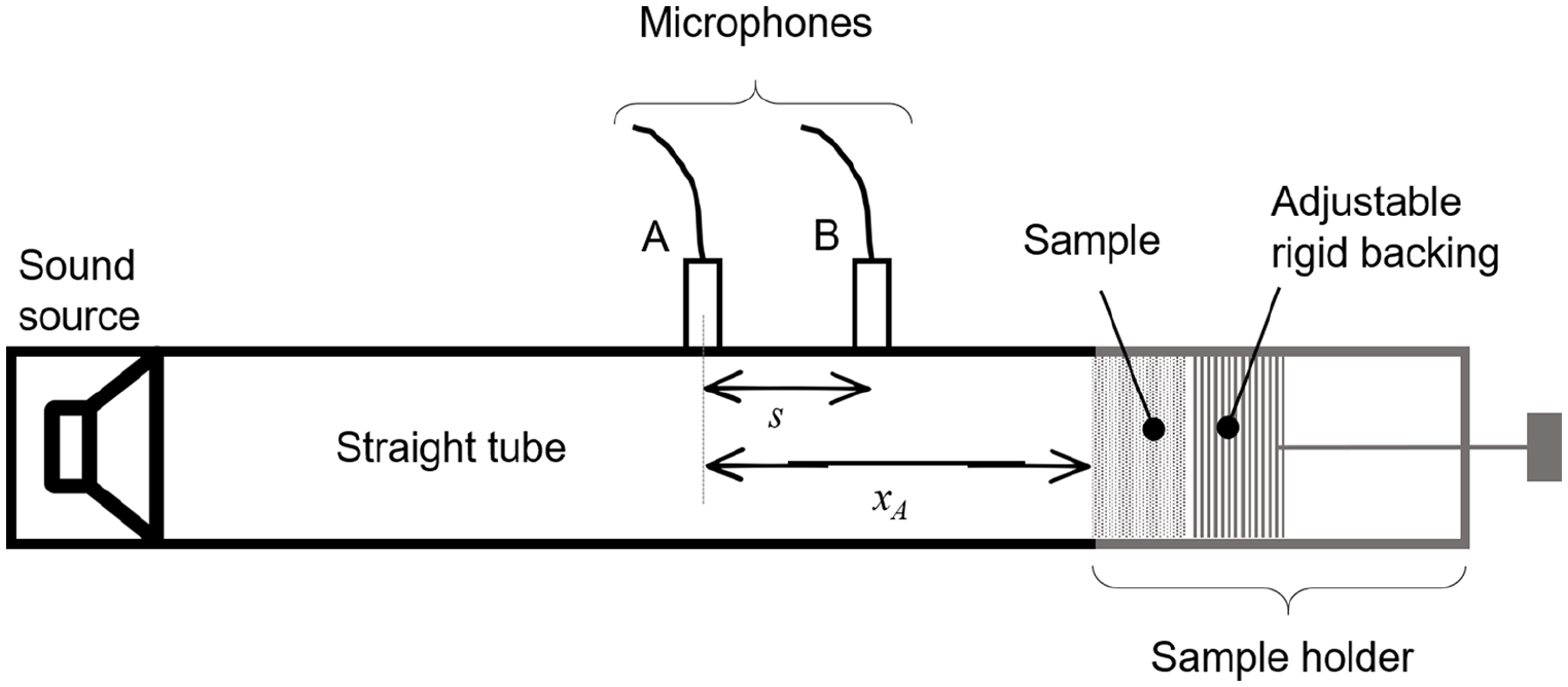
Scheme of a standard impedance tube.
Using the measured complex acoustic transfer function between microphones B and A,
The sound absorption coefficient under normal plane wave excitation is finally evaluated using equation (3).
This experimental method is widely used because it is easy to implement and robust. However, the majority of repeatability errors arise from the sample’s cutting method and its positioning within the tube. In the case of porous materials with an elastic frame, the lateral boundary condition between the sample and the tube wall can have a significant impact on the measurement of the sound absorption coefficient. 53 Indeed, if the sample diameter is too small compared to the tube diameter, air leaks may occur between the sample and the tube wall.54,55 On the other hand, if the diameter of the sample is too large, the vibration of the sample frame and the pore compression will alter the measurement of the sound absorption coefficient.56–59 Note that an alternative method 53 has been proposed to reduce the effects of the lateral boundary condition in the tube. This method allows to estimate the sound absorption of material when a sample of this material is tested in the tube with a small lateral air cavity (same as a lateral air ring). Additionally, the lateral dimension of the test sample, determined by the tube diameter (typically 29.9 mm, 44.4 mm, or 100 mm), might be insufficient to represent the tested material accurately. This is particularly true for non-homogeneous materials such as shoddy felt.
Note that an application of measurements conducted with an impedance tube is their use in the subsequent determination of the input macroscopic parameters of sound propagation models, like the Johnson-Champoux-Allard and Atalla model with five required parameters 52 or even the Johnson-Champoux-Allard-Lafarge model with six required parameters, see Jaouen et al. 60 A classical two-microphone impedance tube, as well as three- or four-microphone tubes, can be used for these measurements and estimations of material’s macroscopic parameters by indirect methods61,62 or inverse methods.52,63
In this project, the Mecanum conventional tubes (see Figure 2(a)) with circular cross-sections of 44.4 and 100 mm diameters have been used to measure the normal incidence sound absorption coefficient of material samples and to assess some of macroscopic parameters of materials (the viscous and thermal characteristic lengths) used in the Johnson-Champoux-Allard and Atalla model
52
to calculate the equivalent wave number

Reference test benches used to measure/estimate the absorption coefficient under various conditions: (a) impedance tube (Mecanum), (b) acoustic cabin (Mecanum), and (c) reverberant room (Université de Sherbrooke).
Reverberation room and acoustic cabin
The diffuse field sound absorption coefficient of a material sample can be measured using (i) an acoustic cabin (also called alpha cabin or small cabin) for a medium-sized sample of material (see Figure 2(b)) or using (ii) a reverberation room (also called reverberation chamber) for a large-sized sample of material (see Figure 2(c)). The reverberation room method is described in the ISO 354:200315 and ASTM C423-2214 standards and is based on the statistical Sabine approach 20 using a diffuse field excitation. The edges of the sample must be covered to avoid including their contribution in the calculation of the equivalent sound absorbing area (see Figure 2(b) and (c)). The position of the material as well as its area or the ratio between its area, and the volume of the room, can greatly influence the results obtained. A large area of sound-absorbing material prevents a logarithmic decrease of the sound field and therefore an accurate measurement of reverberation times in the reverberant chamber.7,21,22 Too small samples of a sound-absorbing material will lead to overestimated values of its actual absorption coefficients (which can largely exceed unity). To measure the sound absorption coefficient at low frequencies, this method requires large-volume chambers (the requirement in ASTM C423 standard is a minimum room volume of 125 m3) and samples with large sizes (ISO 354-2003 suggests the use of a 10–12 m2 sample).
The absorption coefficient of the material in third-octave or octave bands can be calculated as follows
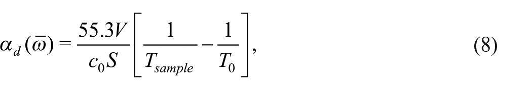
where
Measurements following ASTMC423 standard (interrupted noise method) were conducted at Université de Sherbrooke. The room has a volume of 139.5 m3 (7.5 m × 6.2 m × 3 m). The experimental protocol described in the standard was rigorously followed to guarantee compliance with recommendations regarding all control parameters including microphone positions, sample position and size (6.7 m2). To calculate reverberation times in third-octave bands, signals measured at microphones were filtered in the time domain using third-octave pass bands, Schroeder’s backward integration method was applied to those filtered signals, and the decay rate was estimated over a 15 dB range.
Similarly to an Alpha Cabin,
64
the Mecanum Acoustic Test Cabin is inspired by standardized measurements in a large reverberant chamber14,15 and considers a quasi-diffuse field. Uncorrelated white noise signals are sent to four fixed loudspeakers inside the cabin, and a variable-position four-microphone array is used to measure the sound pressure decay inside the cabin. The room has a volume of 5.95 m3
Equivalent fluid model
Equivalent fluid models, such as the Johnson-Champoux-Allard and Atalla (JCA) model,
52
are based on the assumption that the material behaves as an equivalent fluid. The material frame is considered rigid (or limp) in these models. The JCA model is based on five macroscopic parameters that can be measured/estimated using classical direct or indirect methods: the porosity
Note that the estimation/measurement of macroscopic parameters can be highly dependent on the material sample and the boundary conditions applied to the sample, particularly for macroscopic parameters estimated from acoustic tube measurements. Indeed, as previously mentioned, the lateral boundary condition between the sample and the acoustic tube wall can significantly impact the measurement of acoustic indicators and parameters, particularly for porous materials with an elastic frame. Thus, measurement on several samples of the same material can induce a significant dispersion in the estimation of the macroscopic parameters of the material.
Sound absorption coefficient under a synthesized pressure field - sound field synthesis (SFS) approach
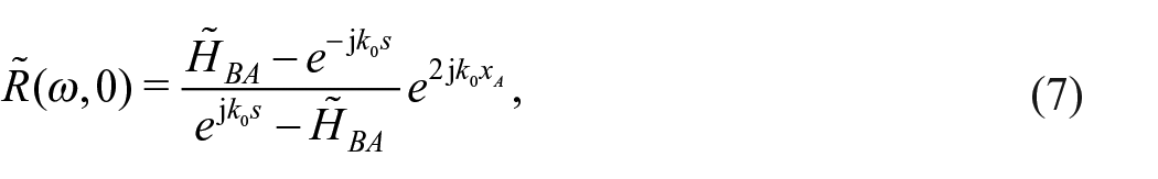
The SFS approach has been described in detail in Robin et al.45,46 so that only the main steps are recalled here. The general principle is to create a given excitation at the surface of a material using a virtual monopole array and a sound field synthesis approach. More precisely, it is based on a spherical decoupling assumption, sometimes called an image-source model.32,69 The spherical assumption introduces a bias for small values of the product of the acoustic wave number
The concept starts with the case of a single monopole over a laterally infinite layer of absorbing material. Considering an ideal point source at a height
with
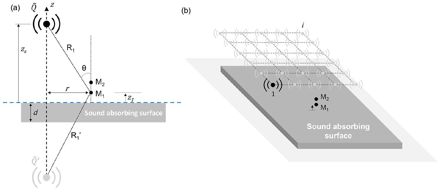
(a) Description of the problem and coordinate system for a single point source and (b) an array of point sources in a plane parallel to the material surface.
Measuring the transfer function between microphone 1 and microphone 2,
Figure 3(b) illustrates the approach proposed in Robin et al.45,46 to reproduce a surface sound pressure excitation described by its spatial cross-spectral density function, such as diffuse acoustic field. A sound source is successively positioned at
where
To summarize this procedure to obtain the sound absorption coefficient under a synthetic sound field, which is referred to as the Sound Field Synthesis (SFS) approach in the following:
A database of complex reflection coefficients under various source position is constructed using equation (10),
This database is coupled to a calculated source volume velocity CSD matrix
The CSD of the target pressure field on the material surface is defined to be an ideal Diffuse Acoustic Field (DAF)
72
or a plane wave with prescribed incidence,
73
The corresponding absorption coefficient
While an ideal DAF implies a 90° limit incidence angle in the theoretical CSD, the largest incidence angle that can be included in the database of measured reflection coefficients is defined by the source to reproduction plane separation
Proposed characterization approach: Allard model inversion (AMI)
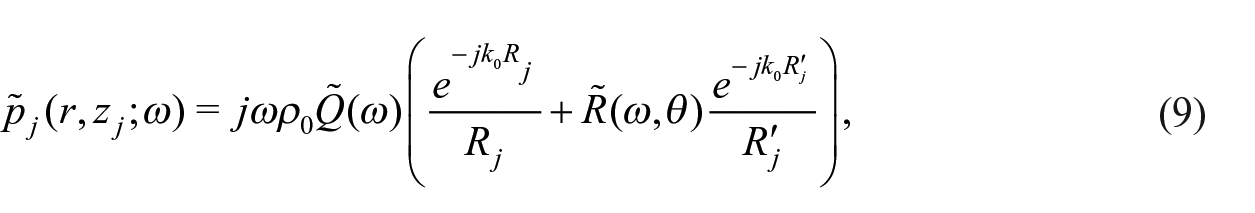
Similar to the SFS approach, the material characterization approach proposed here is based on a mobile loudspeaker and a pair of fixed microphones above a layer of absorbing material. Assuming that the loudspeaker behaves as an omnidirectional point source and neglecting waves diffracted by the edges of the material sample, the problem corresponds to a monopole source
According to Thomasson
74
and Allard et al.
40
and referring to Figure 3(a), the sound pressure at location
where
Using the experimental test bench described in Section 5, a loudspeaker is moved at a series of positions
where
Since measurement noise has a larger impact on low frequency material property extraction, the calculation is initiated at the highest frequency of interest, starting from user-defined initial values for the complex properties
Upper and lower bounds for
The minimization algorithm solves equation (13) at the highest frequency of interest;
The calculation is repeated at the next frequency bin, using as initial estimates the optimal values of
Once the optimal material properties
Figure 4 presents a graphical summary of the methods considered and compared in this work.
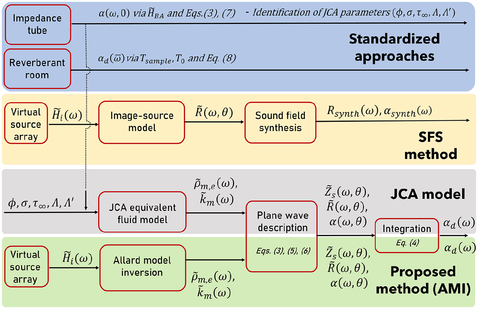
Graphical summary of the approaches considered in this work.
Experimental methods
Test bench: Design, instrumentation and data processing
Previously, when the SFS method was implemented,45,46 the acoustic source was manually moved/positioned by the operator (the test bench was not automated), which could induce errors in the position of the source and repeatability. Moreover, measurements could be time-consuming for the operator. To implement the SFS and AMI methods using repeatable and reproducible measurements, a specific and automated test bench was developed to meet the following specifications, see Figure 5. The test bench must allow for measuring the transfer functions between two fixed microphones and a sound source at a given position above the material. The sound source can be translated along a plane area above the sample. The distances between the source and the microphones must always be accurately known for all source positions. Considering these distances, the area of the virtual source array must be sufficiently large (at least 1 m2), and the sample surface has to be at least equal to that of the virtual source array.45,46 Two parallel actuators allow moving the source in the x-plane, and one actuator perpendicular to these moves the source on the y-axis (see Figure 5(a)). Two motors are connected to each axis and are controlled by motor control and feedback boards. The system is servo-controlled, and correctors are used to improve the setpoints to obtain precise and repeatable position values. The rest of the structure is made up of aluminum profiles to ensure rigidity and system stability during measurements. Reflections of sound waves off the bench elements or adjacent walls can induce significant errors in estimating the sound absorption coefficient. For this reason, parts of the aluminum profiles of the bench were covered with thick sound absorbers (glass wool and melamine foam) and the bench was positioned in the hemi-anechoic chamber of ICAR laboratory (Infrastructure commune en acoustique pour la recherche de l’École de technologie supérieure - Institut de recherche Robert-Sauvé en santé et en sécurité du travail) (see Figure 5(a)).
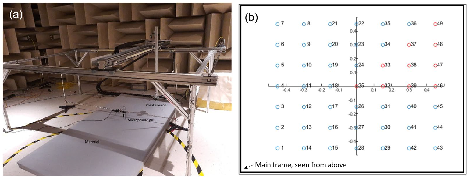
(a) Picture of the test bench installed in the hemi anechoic room and (b) numbering of the source positions (horizontal axis is
LabVIEW software was used to create a code and user interface to control the bench and perform measurements. The code sends instructions to the actuators to move the source along a grid above the material and, for each position, performs the measurements (generation of the source signal, acquisition and processing of the signals measured at the microphone pair). The sound source is an RCF 5055 compression chamber, with a 100–5000 Hz bandwidth. Sound pressure signals are measured using two phase-matched half-inch microphones (G.R.A.S. 40 GK). Signal acquisition and generation are performed using a NI-4431 card. Three inputs are used to acquire the signals from the two microphones, one for the return of the signal sent to the source, and one output for transmitting the excitation signal to the source. For each source position along the virtual mesh, a logarithmic swept sine on the 100–5120 Hz frequency range and over 2 s (improved signal-to-noise ratio at lower frequencies than a linear swept sine) and 20 averages with no overlap were considered. These parameters lead to a good compromise between the results’ quality and the measurement’s overall duration.
In this paper, a microphone separation of 5 cm along the x and y-axis of the grid, a height between the lowest microphone and the surface of the material of 5 cm, a height of 30 cm between the source and the surface of the material, and an array of 7 × 7 sources covering a mesh area of 0.9 m × 0.9 m were used. This set of parameters arises from previous work. 46 The mesh of the successive positions for the mobile source is schematically described in Figure 5(b), the subset of 10 source positions used for the AMI method is indicated by red circles. This subset forms a non-redundant set of source positions for homogeneous, isotropic absorbing materials.
Tested materials
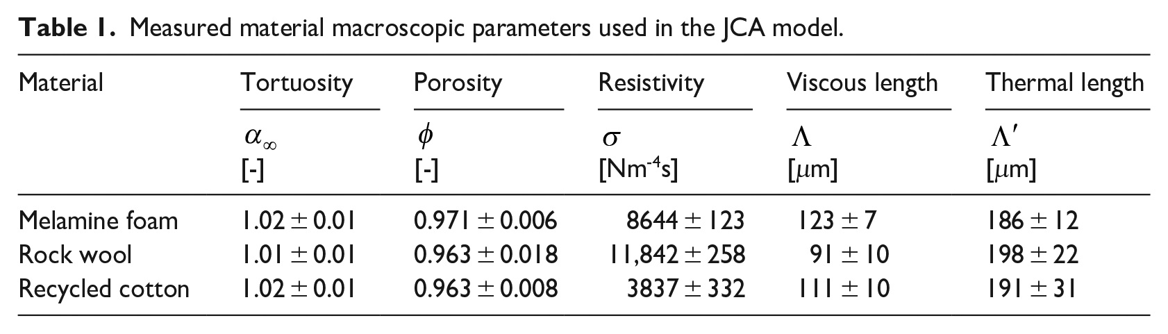
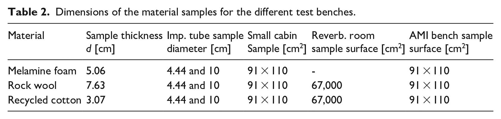
Three sound-absorbing materials were considered in this work: a 50.6 mm thick melamine foam, a 76.3 mm thick rock wool, and a 30.7 mm thick recycled cotton. The five macroscopic parameters required for the JCA model were measured in the GRAM-ICAR lab of Groupe de Recherche en Acoustique à Montréal (GRAM) at École de technologie supérieure.
The mean value and the standard deviation of the obtained JCA parameters for the three materials are listed in Table 1, and the methods used to measure or estimate these parameters are detailed in the Equivalent fluid model Section. Photographs of samples used for impedance tube measurements are shown in Figure 6. The dimensions of the samples of the three materials used in the different test benches are given in Table 2.
Measured material macroscopic parameters used in the JCA model.
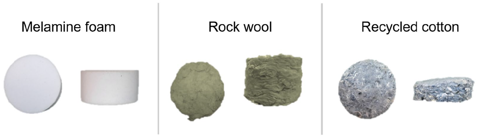
Front and side pictures of samples of the three materials for impedance tube tests.
Dimensions of the material samples for the different test benches.
Results
Complex wavenumber and complex density
This section reports the complex wavenumber
Since all materials tested are assumed transverse isotropic, there are redundant source positions among the 7 × 7 measured positions. A subset of 10 source positions, corresponding to a non-redundant octant of the square source array, was used to minimize the cost function in equation (13). The initial values of the gradient-descent search for the highest frequency (2 kHz) were set to
Figures 7–9 show the identified wave number and material effective density (real and imaginary parts) for melamine, rock wool and recycled cotton, respectively. They are compared with Johnson-Champoux-Allard (JCA) predictions based on the measured/estimated macroscopic parameters presented in the previous section. The Allard model inversion provides results similar to the JCA predictions in the higher frequency range for melamine and rock wool. The deviations between the identified properties and the JCA model become larger below 400 Hz, especially for the complex density, because measurement noise, as well as spurious reflections from test bench components and diffraction by edges of the material sample become important at low frequency.
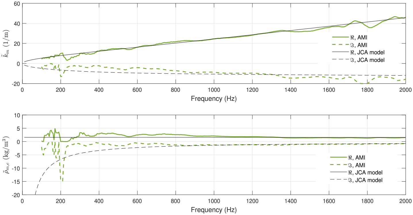
Identified wavenumber
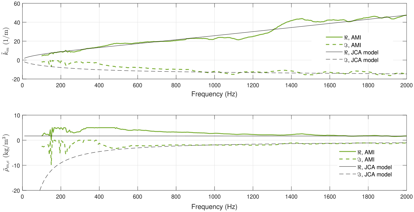
Identified wavenumber
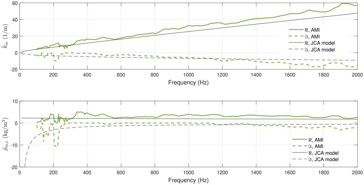
Identified wavenumber
More significant deviations are observed for recycled cotton between the measured properties and the JCA model (notably for the real part of the wavenumber). It is believed that recycled cotton exhibits more heterogeneity than melamine and rock wool, as well as more significant variations in thickness. This may explain the larger differences between the Allard model inversion and the JCA model (for which some macroscopic parameters are extracted from a small material sample).
It is also essential to remember that the proposed approach and validation results assume an equivalent fluid response of the materials, the used model cannot describe sound-absorbing materials for which the solid phase has a significant elastic response. We underline that there is no suspicion of a significant skeletal elasticity effect in the results shown for the three considered materials, except for the melamine foam whose sample in the impedance tube seems to exhibit a frame resonance (see section Comparison of sound absorption coefficients). This being said, precautions should be taken when applying the approach to materials that could exhibit an elastic response.
Comparison of sound absorption coefficients obtained with the AMI method and reference approaches
In this section, the sound absorption coefficients obtained with the AMI method are compared with those calculated using JCA’s model based on porous material properties presented in Table 1 and the SFS method. Sound absorption coefficients measured using the impedance tube are also provided for the normal incidence case. For the diffuse field case, measurements in a small cabin and a reverberant room (for the rock wool and the recycled cotton) are considered for the three materials.
Normal and oblique incidence sound absorption coefficient
For the sake of conciseness, only the results for the melamine foam are presented here. Similar trends are obtained for the other materials at low frequencies. For some materials, mainly recycled cotton, discrepancies are observed between the reference/impedance tube method and the SFS and AMI methods. These differences also appear in diffuse field excitation and are discussed in the following Subsection. Figure 10 (respectively Figure 11) compares the normal (respectively oblique at
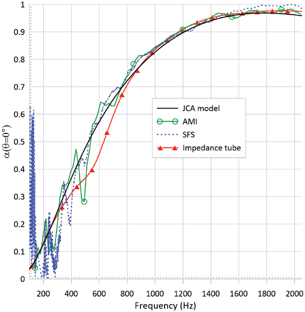
Normal incidence sound absorption coefficient
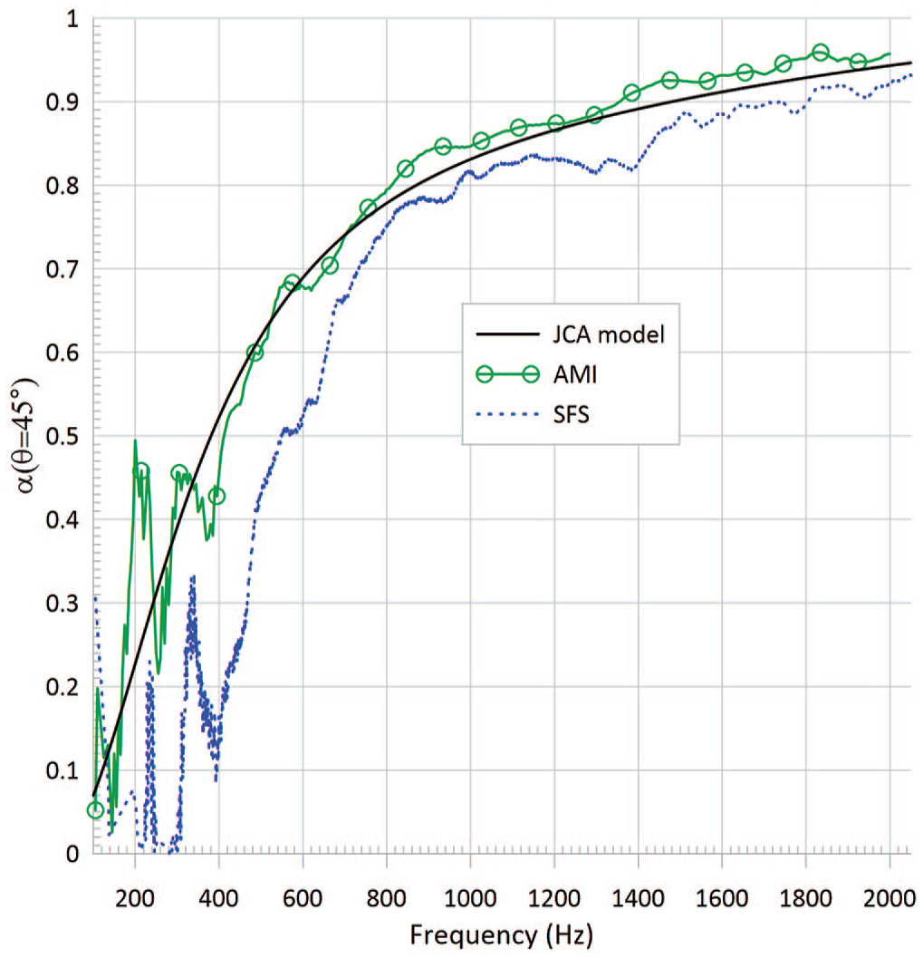
Oblique incidence sound absorption coefficient
Calculated RMSD for the estimated normal
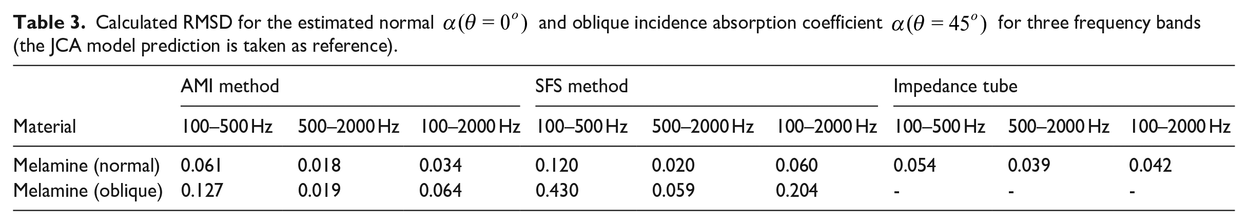
For the normal incidence, the impedance tube provides sound absorption values generally in excellent agreement with JCA’s model (Root-mean-square deviation of 0.042 with the JCA model over the 100–2000 Hz frequency range) except between 400 and 800 Hz, where discrepancies are noted. These could be due to the first frame resonance of the sample in the tube; indeed for the JCA’s model, the material frame is supposed to be rigid (or limp). The results obtained via the AMI and SFS methods match very well with JCA’s model above 500 Hz (with RMSD values of 0.018 and 0.02, respectively). Below this frequency, the AMI and SFS methods give results that follow the model quite well on average, down to 100 Hz for AMI and 200 Hz for SFS, even though some oscillations appear. For the AMI method, these oscillations are directly related to those revealed in effective density and wave number identifications. Note that the SFS method leads to noisier data below 300 Hz and can even lead to negative sound absorption coefficient values. This is translated in an RMSD of 0.120 in the 100–500 Hz frequency range, twice the RMSD obtained in the case of the AMI method. For the oblique incidence, despite some oscillations below 400 Hz, the sound absorption coefficient obtained with the AMI method follows the JCA model. For the SFS method, the sound absorption curve deviates significantly from the reference value below 700 Hz and even leads to negative values of
Diffuse field sound absorption coefficient
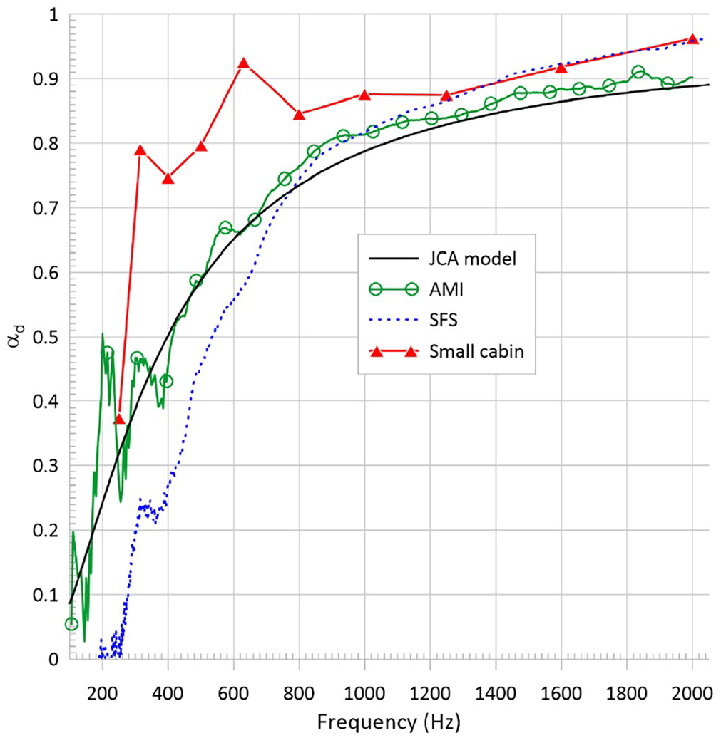
Figures 12–14 compare the diffuse field sound absorption coefficient obtained with the AMI method and the reference approaches. The three tested materials are described in the Tested Materials Section. As in the previous section, the root-mean-square deviation (RMSD) is used to evaluate the error
Diffuse field sound absorption coefficient
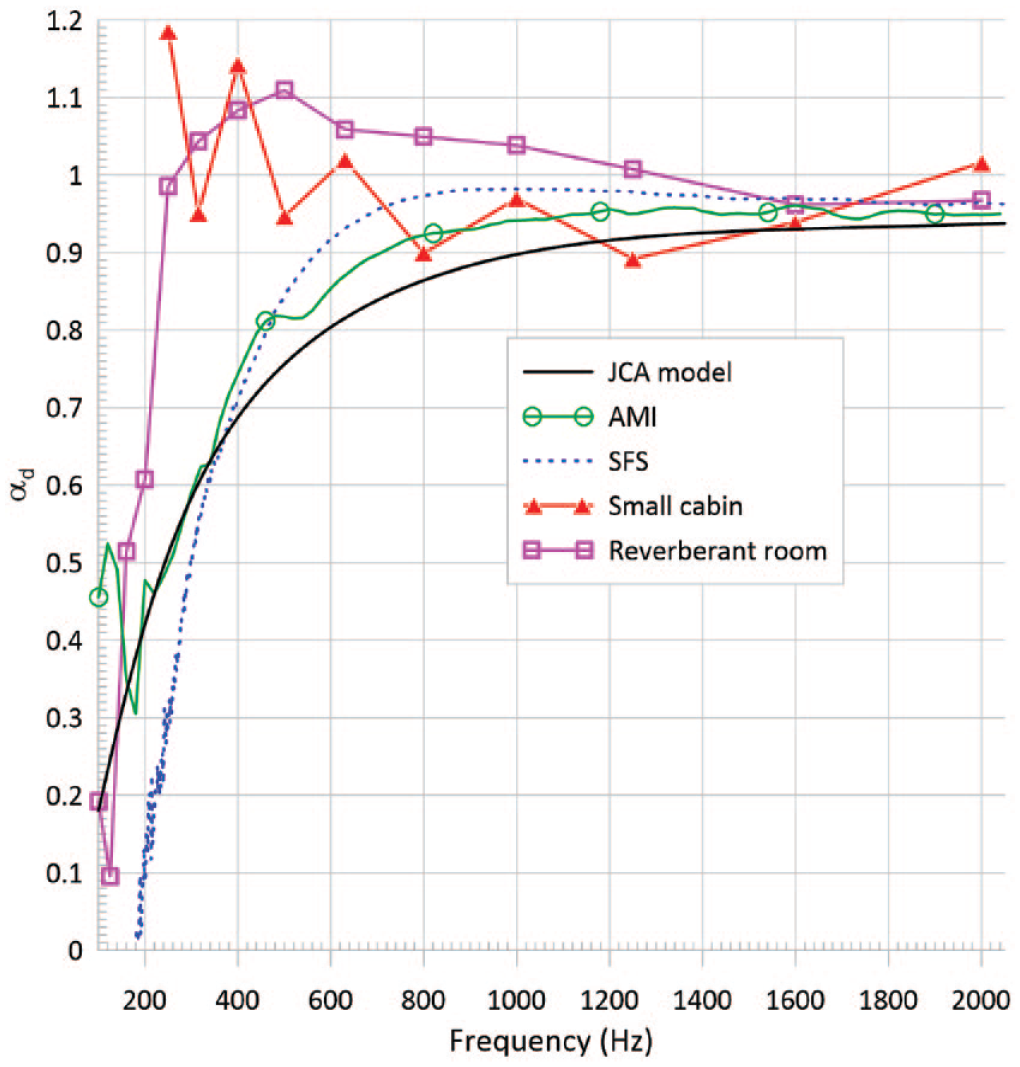
Diffuse field sound absorption coefficient
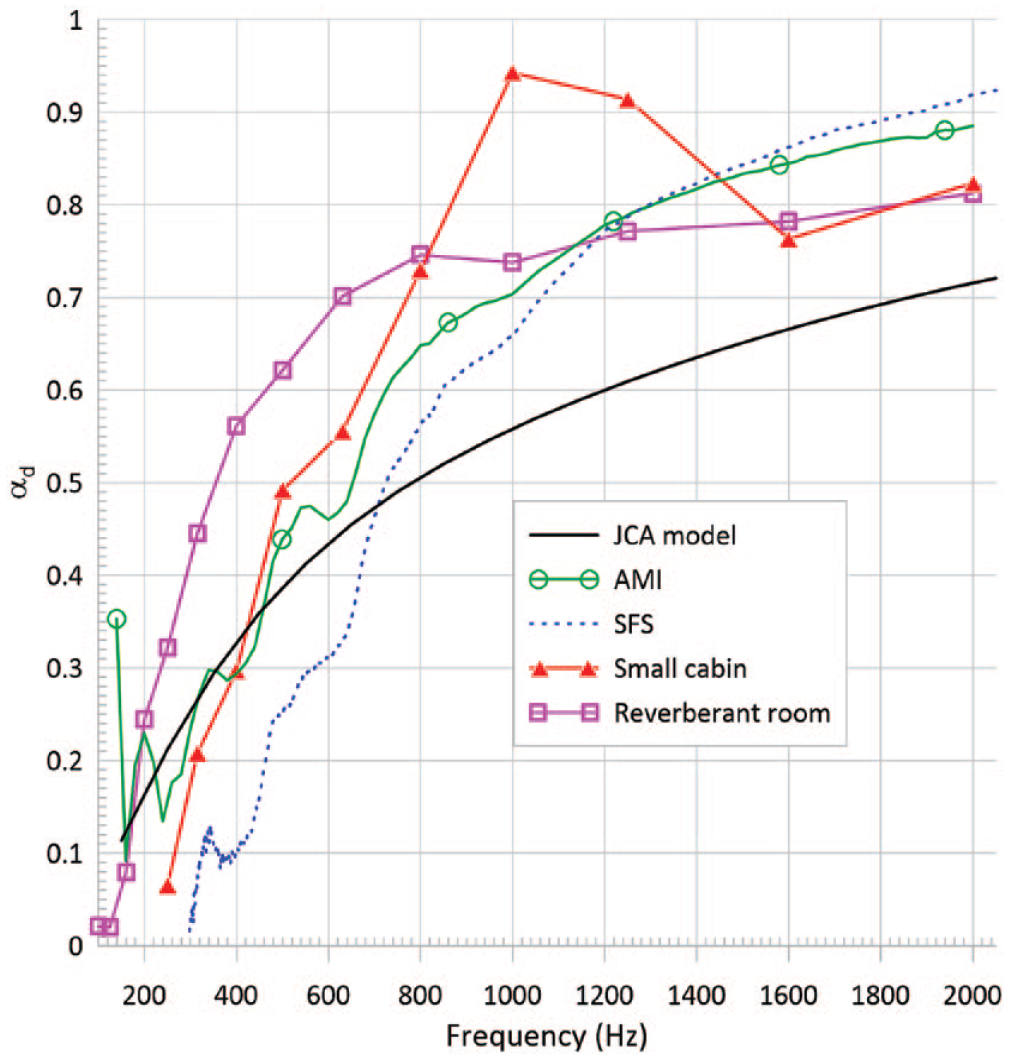
Diffuse field sound absorption coefficient
Calculated RMSDs for the estimated diffuse field sound absorption coefficient
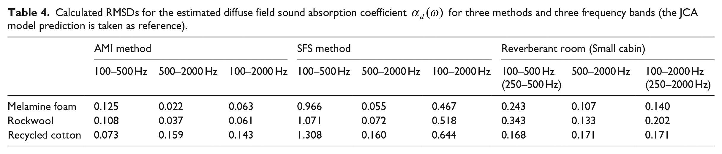
Regardless of the material considered, the sound absorption coefficients obtained from reverberation time measurements are overestimated compared to models or other estimates. In the case of the rock wool, see Figure 13, the results often exceed unity, making them unusable in room or building acoustics simulations. The JCA’s model provides results that are close to the AMI method for all the materials, particularly at low frequencies down to about 200 Hz. Indeed, the RMSDs obtained with the AMI method are always lower than those obtained with the reverberant room method. Similarly to the plane wave incidence excitation field, oscillations associated with the identified values of the material acoustic properties are observed in AMI’s diffuse field absorption coefficient. The SFS method leads to similar results to the AMI method above 800 Hz, with a generally lower error for the AMI method in the 500–2000 Hz range. Despite using the bench, which reduces uncertainties compared to the previous study on SFS, 46 the precision of the SFS method is still limited in the low-frequency range because of the inaccurate image source model involved. Large negative values of the sound absorption coefficient lead to larger RMSDs for the SFS method in the 100–500 Hz frequency range. However, these RMSDs are still lower than those obtained with the reverberant room method in the 500–2000 Hz range. In the case of recycled cotton, see Figure 14, both AMI and SFS methods lead to a poor agreement with the JCA model at frequencies above 600 Hz. Therefore, as experimentally observed, the absorption coefficient of the material is very sensitive to the sample’s dimensions and lateral boundary conditions. These dimensions and boundary conditions differ between the samples used for the impedance tube measurements (used to indirectly identify the JCA model’s viscous and thermal characteristic lengths) and the samples used for the test bench measurements. In concrete terms, this corresponds to a small circular sample held on all its edges in the impedance tube versus an assembly of samples of different finite dimensions and free of lateral stress for the bench. The spatial inhomogeneity of the material thickness, which is not considered in the Allard model and therefore does not allow for a good estimate of the effective density and wave number, is the preferred hypothesis to explain the differences observed between the methods.
Discussion
From the measurements performed on the developed test bench, the AMI method allows for the identification of two effective (or equivalent) parameters, namely the complex effective density and the complex wave number. Starting from these two parameters, it is possible via the equivalent fluid model to calculate quantities such as the surface impedance or the sound absorption coefficient. The total computation time to arrive at the target quantity, that is, the sound absorption, is on the order of a few minutes (using a laptop equipped with an Intel core i7 processor, with a FLOPS performance around 100–200 gigaFLOPS).
The three main advantages of this method are:
The complex effective density and the complex wavenumber are classically obtained by impedance tube measurements and the use of various dedicated benches that require careful preparation of small samples (at most one square decimeter). Since the AMI method operates on sample sizes of the order of the square meter, no special attention should be paid to the sample preparation.
Once the complex effective density and the complex wave number are obtained, it is possible to estimate the acoustic absorption coefficient for any angle of incidence for a plane wave, or under diffuse field by summation over the elevation angles (in the case of isotropic materials) and to even vary the maximum incidence angle in the computation of
The low frequency limitations for this method are pushed back to a frequency as low as 100 Hz, and even if the identification of the two complex parameters is sometimes imperfect, the estimation of the sound absorption coefficient is relatively unaffected by these imprecisions (especially for the diffuse acoustic field case). It is, therefore, possible to estimate the sound absorption coefficient for plane waves with arbitrary angle of incidence, or for a diffuse field, and this for samples of reduced dimensions compared to the reverberation chamber method. The values obtained are always in a physical range (between 0 and 1) and are therefore directly usable in room acoustics simulations.
The limitations of this method lie mainly in the assumptions associated with the Allard model to describe the sound field above the material. In particular, the material is assumed to be laterally infinite, isotropic, homogeneous, of constant thickness, and to behave like an equivalent fluid. Furthermore, the assumption of isotropy results in an absorption coefficient that depends only on the elevation angle of incidence
Furthermore, it should be noted that in the case of the diffuse field excitation, the estimation of the absorption coefficient by the SFS method proposed in Robin et al.
46
using the improved measurement bench remains accurate and interesting for the frequency range considered, especially if these results are compared to the overestimated ones obtained by the standard reverberation chamber method and for sample surfaces of area 7 m2. However, limitations in the low-frequency range remain similar to those mentioned in Robin et al.
46
(below 400–600 Hz depending on the tested material). Also, the SFS method includes a limit incidence angle for the DAF that is linked to the maximum incidence angle that is included in the measured reflection coefficients. Regarding the sound absorption coefficient under plane wave type fields in normal and oblique incidence which have been studied more specifically in this work, estimation remains accurate, but only above a frequency of about 500 Hz (frequency that depends on the material and the exciting field considered). The frequency limitation is more severe in the case of the plane wave because the synthesis in specific directions or angles of incidence becomes problematic for a fixed source array, unlike the case of the diffuse field, which involves an average over the angles of incidence. In summary, the SFS method does not allow for an accurate estimation of the sound absorption coefficient at low frequencies. However, in its domain of applicability (medium to high frequencies), this synthesis method has the advantage of having a very short post-processing time (on the order of a few seconds). It could help develop new materials for which small surfaces are available. It is also possible with this synthesis method to vary not only the angle of incidence
Conclusion
This paper proposes a method to extract equivalent fluid properties (frequency-dependent complex wave number and complex effective density) of a sound absorbing material by inverting the Allard propagation model for a point source above the material surface (AMI method). The method uses a dedicated experimental test bench with a mobile loudspeaker and a pair of fixed microphones above the material’s surface. The equivalent material properties are extracted by fitting the measured inter-microphone responses for a set of loudspeaker positions, to the responses predicted by the Allard model. The plane-wave and diffuse-field absorption coefficients can be deduced from these equivalent material properties. The absorption coefficients obtained with this method have been compared to standard methods (impedance tube and reverberant chamber measurements), as well as to small cabin measurements, JCA model predictions, and results obtained with a Sound Field Synthesis approach (that used data collected with the same experimental test bench).
For the two reported materials that comply with equivalent fluid assumptions (melamine and rock wool), the AMI method provides absorption coefficients in good agreement with the JCA model or impedance tube measurements; in particular, the AMI method shows improved results in low frequency when compared to the sound field synthesis method (SFS). For these materials, the sound absorption coefficient can be estimated for plane waves with arbitrary angle of incidence, or a diffuse field, and this for samples of reduced dimensions compared to the reverberation chamber method. However, the AMI method only applies to isotropic, homogeneous and constant-thickness materials. Materials including spatial inhomogeneities, non-isotropic materials, or materials whose skeleton can deform cannot be characterized using this method. The use of an automated measurement bench, combined with various post-processing methods, suggests an interesting and robust alternative to standard methods (impedance tube method, reverberation chamber method), including the possibility of taking into account various acoustic excitations (diffuse field, plane wave at variable incidence).
Footnotes
Appendix 1—Johnson-Champoux-Allard model
The Johnson-Champoux-Allard and Atalla (JCA) model
52
is an equivalent fluid model based on five macroscopic parameters:
with the Biot’s cut off angular frequency :
where
The functions F
Then, the equivalent characteristic impedance and the equivalent wave number are given by:
Acknowledgements
The authors thank Mathis Vulliez, Raphaël Jeanvoine, Lucien Guerbigny, Marion Lautier for their support to mesurement and simulation campaigns, and to Patrick Lévesque, Olivier Bouthot, Thomas Padois and Fabien Bonnet for their technical assistance.
Declaration of Conflicting Interests
The author(s) declared no potential conflicts of interest with respect to the research, authorship, and/or publication of this article.
Funding
The author(s) disclosed receipt of the following financial support for the research, authorship, and/or publication of this article: This work was supported by Institut de Recherche Robert Sauvé en Santé et en Sécurité du travail (Grant 2018-0027).