
Abstract
Vertical greening can be used to absorb and scatter sound, which may reduce noise levels in street canyons. In this paper, a literature review is presented, which combines results and methods from over 40 individual studies. The article describes the guiding principles behind the acoustic effects of vertical greening and provides an overview of the prevalent research methods. The article shows that vertical greenery is effective for the reduction of mid and high frequency noise, unless air cavities or resonators are introduced inside, or behind, the systems. The review also reflects on studies with an emphasis on the application of vertical greenery in streets and urban blocks. The aim of the article is to set out the key design parameters for noise reduction that can be achieved by vertical greening, focusing on designers and engineers.
Introduction
The WHO estimates that almost one-third of the global population lives in areas with severe and persistent noise levels. Nighttime noise reduces the quality of sleep of roughly a fifth of the world population. After air pollution, the WHO sees noise as the most important health concern for cities. 1 Various studies indicated that the exposure to severe noise levels over a longer period of time contributes to stress-induced health effects, including cardiovascular diseases (hypertension, ischemic heart disease, high blood pressure), cognitive impairment in children, tinnitus, less focus and poorer mental well-being.1,2 The estimated social costs in the EU equals 0.4% of its GDP. 3 For the year 2000, it was estimated that roughly 44% of all Europeans were exposed to noise levels deemed as “severe,” 4 mainly in cities. On a global level, the combination of ongoing population growth and urbanization 5 will increase the amount of people exposed to high levels of (traffic) noise, especially in the Global South. 6
The way cities are designed plays an important role in the propagation of sound. The orientation and perimeter of building blocks can locally shield walls and courtyards from traffic sound. Facades are traditionally comprised of acoustically reflective materials.7,8 Acoustically hard materials lead to reflections between facades, prolonging the duration of exposure, or leading to modal behavior in streets and buildings. This can lead to high sound levels in so-called “source canyons,” but it could also exacerbate sound levels in surrounding canyons and adjacent courtyards. This can be prevented by changing the acoustic absorption of walls, for instance by mounting vertical greening on facades. 9
In cities, most traffic sound is emitted by road vehicles. 10 Typically, noise from road vehicles contains acoustic energy across the spectrum audible by humans. Traffic noise in cities is mainly the consequence of friction between tires and surfaces, followed by sound emitted during fuel combustion in engines, and vibrations in the exhaust systems. 11 This means that sound levels in cities generally peak below 125 Hz 12 for unweighted sound pressure levels. This image changes after sound levels are corrected for the human sensitivity to frequencies, for example, by applying an A-weighting. As the correction for lower frequencies is greater than for mid frequencies, the peak intensity of road traffic noise in streets shifts to 1000 Hz. 13 For vehicles with a higher and more regular speed, sound mainly depends on the friction between the road surface and the tires, and between air and the frame. This means that frequencies well above 1000 Hz contain most acoustic energy. Consequently, the next generation of cars are not automatically less noisy. Despite that vehicles have become quieter, and many European cities have ramped up efforts to reduce the number of cars since the early 2000s, it is not expected that noise levels will drop rapidly within the EU for the foreseeable future. 3 Literature shows that electric vehicles are only quieter than traditional cars for speed below 50 km/h. 14
Aside from road traffic, areas close to airports experience many issues that relate to aviation noise, which is seen as one of the most disturbing and irritable noise sources. In terms of annoyance, based on equal sound levels, aviation noise scores worse compared to noise from cars and trains. 15 Unless airplanes are taxiing, aircraft noise is much harder to reduce by means of barriers. 16 Aviation noise generally contains a high intensity of low frequency noise as well, which is less well absorbed in the atmosphere, and travels over much greater distances due to long wavelengths of the sound.17,18
During the past decades a great number of studies have presented and tested strategies to reduce (traffic) noise. Vegetation is often seen as a viable strategy against noise pollution, as it can help to reduce noise, or improve the perception of noise. The acoustic attenuation of vegetation and greenery formed a cornerstone of the EU-funded HOSANNA project. 3 Despite that most work of the project went to the development of novel and sustainable noise abatement methods with natural means, HOSANNA also included an extensive literature review focussing on crossovers and conflicts between existing studies.
Examples of studies that were published before the start of HOSANNA in 2009 include research on the acoustic effects of tree belts, 19 and leaf vibrations. 20
Partially in tandem with HOSANNA, the VegDUD project (2010–2014), funded by the French National Research Agency, focused on the benefits of vertical greening. Compared to HOSANNA, VegDUD had a broader and interdisciplinary scope, focusing not only on sound abatement, but also on water retention, evaporation (i.e. cooling), added shading, biodiversity, and air purification. 21 Aside from HOSANNA and VegDUD, there have been numerous individual studies which focused on the acoustic and micro-climatic properties of vertical greening. Next to acoustic and micro-climate properties, there are also many papers discussing other aspects of green walls. Manso et al. 22 for instance provide a review of benefits and costs of green roofs and green walls, Rowe et al. 23 discuss their environmental impact based on life cycle assessment, and Ahsan et al. 24 map the entire field of research on vertical greenery systems identifying several subfields, one being acoustics.
However, a comprehensive literature review on the acoustic properties of vertical greening systems for outdoor applications, setting out the underlying acoustical principles, is still lacking. Understanding these fundamental mechanisms is necessary to develop new green walls with improved sound absorption performance, especially for the abatement of low frequency noise. Studies addressing the acoustics of green walls about outdoor applications will therefore be reviewed in this paper. Different from two other review studies by Yan et al. 25 and Oquendo-Di Cosola et al., 26 this article puts the emphasis on the application of underlying acoustic principles and research methods by design and engineering scholars and practitioners.
Research method
Traditionally, vertical greening is not (in the first place) designed to attenuate sound in rooms or streets. 6 Yet, the acoustic absorption yielded by the substrate, which supports the plants, makes it a natural, and more sustainable, alternative for synthetic sound absorbent materials. 27 To what extent substrates and vegetation affect incident sound is not always clear, as peer-reviewed articles use(d) different research methods, for example, numerical simulations, laboratory or in-situ measurements, or focus(ed) on different frequency spectrums. or focus(ed) on different frequency spectrums. The variety of studies and outcomes makes it difficult to identify the key indicators for the acoustic performance of VGS, especially for designers and manufacturers of VGS.
This article presents a literature review examining the acoustic properties of vertical greening systems (VGS). The objectives of the article include:
Providing an overview of all relevant papers in the field of acoustics and vertical greening systems (VGS from now on).
Deducing the main (physical) principles that are relevant for the acoustic attenuation of VGS based on individual studies.
Setting directives to stream-line research methods and to define a homogeneous frequency range for studies on VGS and acoustic absorption.
Mapping research gaps which are relevant for future research.
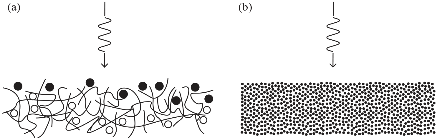
Vertical greening is an umbrella term which includes many different types of systems, such as (in)direct green facades and various living wall systems (LWS). 28 All systems comprise vegetation, a substrate and a vertical “hosting” surface, and can be applied both in- and outdoors. 29 Figure 1 shows the most common VGS, based on the work of Ottelé. 30 All systems require a substrate for the roots, placed vertically (LWS) or at the foot of the wall (green facades), sustaining a plant layer. In indoor environments, vertical greening can reduce reverberation which improves speech clarity with pivotal frequencies between 125 and 8000 Hz. In outdoor settings the frequency spectrum of interest often also includes frequencies lower than 125 Hz. In outdoor settings the frequency spectrum of interest often also includes frequencies lower than 125 Hz. Although challenging, this means that in outdoor environments vertical greening ideally contributes to a reduction of a broadband spectrum including frequencies lower than 125 Hz and higher than 8000 Hz. Hence, all studies reporting results in the frequency range between 20 Hz and 20 kHz were included in the literature review. This spectrum corresponds to the sensitivity of the human ear.
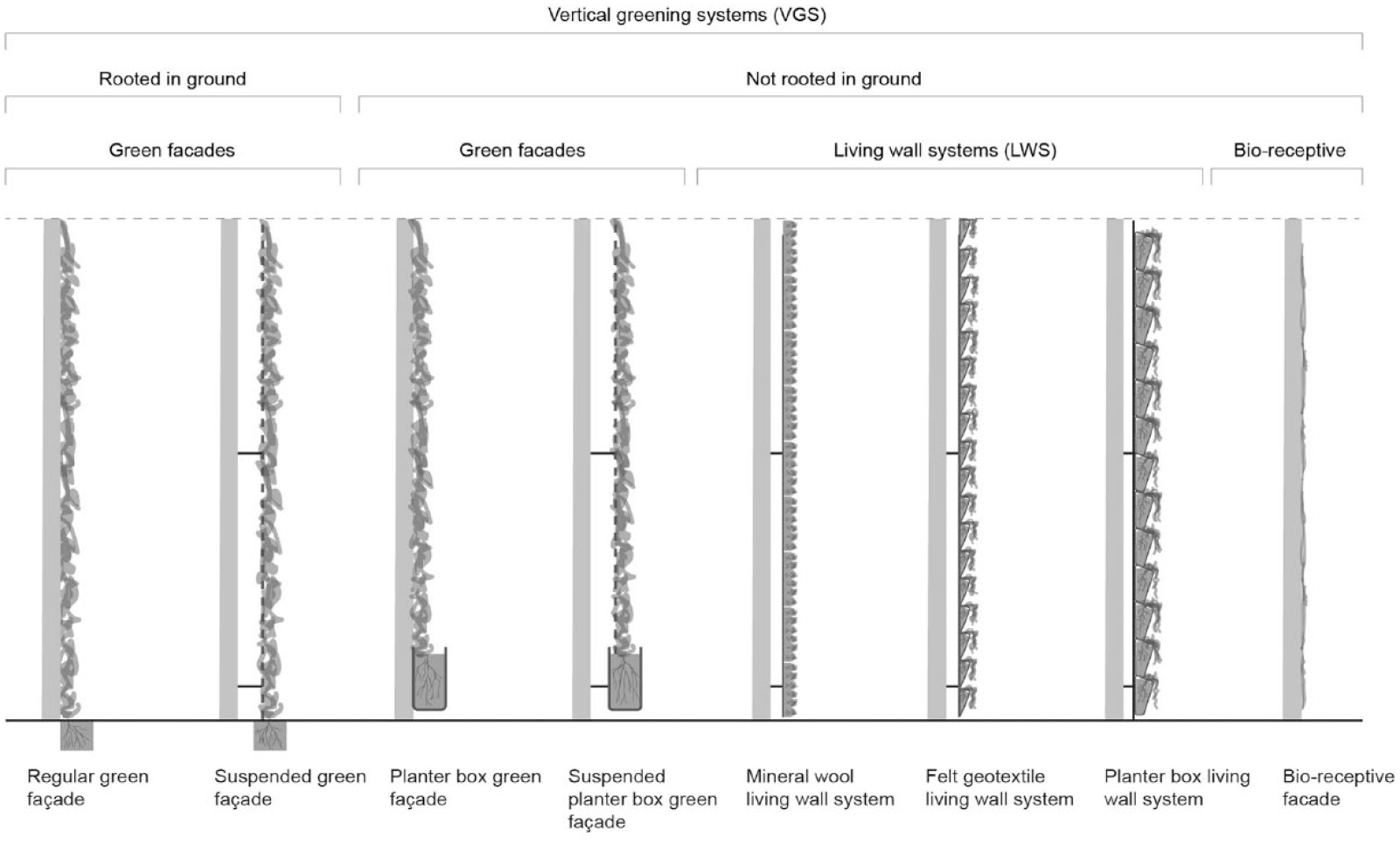
Vertical Greening System types (Based on Ottelé 30 ).
Most peer-reviewed papers which present results on the acoustic performance of vertical greening refer to more fundamental studies, which only focused on isolated issues like the acoustic properties of leaves, soil and/or plants. These studies provide an important basis to fully understand the physics behind acoustic absorption and VGS and are therefore included as well.
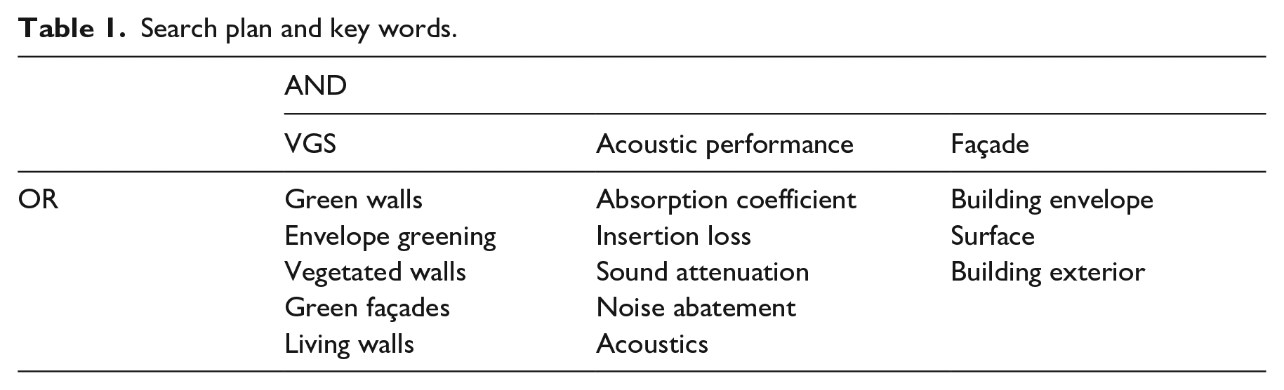
Various databases were used to find relevant literature, including ResearchGate, Google Scholar, Scopus, and Web of Science for digitally published articles. The study focused primarily on peer-reviewed articles, but also included (hand)books. Table 1 lists the synonyms of the most important search terms as used for this research, corresponding to different synonyms for VGS.
Search plan and key words.
Before a final selection of relevant studies was made, a series of steps were taken. First, individual studies were categorized in a spreadsheet, which made it easier to spot links and gaps between studies. This circle was repeated until “newly found” articles only referred to articles that had already been included in the spreadsheet.
In total, 40 sources were included in the spreadsheet, varying from handbooks to peer-reviewed papers. In a second step, information about research methods and outcomes were summarized. Figure 2 shows a breakdown of the main topics, and/or sources consulted or included in this literature review.
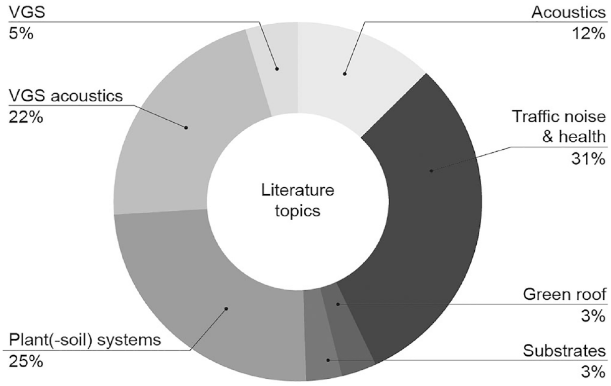
Literature topics of referenced sources.
Figure 3 shows a breakdown of research methods which were used in relevant studies. The figure shows a variety of methods, including analytical, numerical, and experimental methods (i.e. impedance tubes, reverberation rooms, and in-situ measurements).
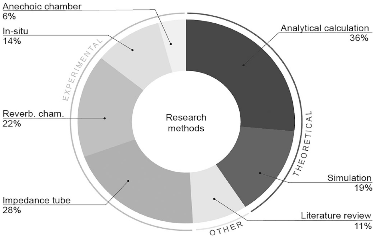
Research methods of referenced sources.
The majority of the 40 sources which were deemed relevant for the literature review had been published over the past decade. However, a few studies on the basics of vegetation and acoustics, providing the bedrock for later studies, date from the 1980s and 1990s. Figure 4 plots the most common authors, and/or scientists referenced to, in the literature as assessed for this study.
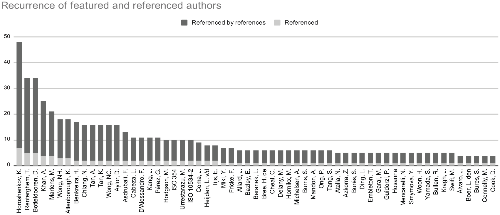
The graph displays how often authors are cited in the literature review (referenced – in gray), or (indirectly) cited in articles which were included in the literature review (referenced by references – in black).
The conclusions from the literature review are presented in the next part of this paper. The first part discusses the mechanisms behind the sound absorption of the substrate and plant layer separately. The second part focusses on the acoustic properties of combined substrate-plant systems, followed by a discussion and conclusions section.
Sound absorption by substrates
Substrates are porous absorbers inducing viscous-thermal damping. The acoustic absorption of porous materials is described by various models, see for example, the online manual APMR for an overview. 31 Air is a viscous fluid and is therefore subject to boundary layer effects at the pore’s walls. These frictional viscous forces convert sound energy into heat. 32 The visco-thermal absorption of the substrate is the main sound attenuating phenomenon occurring in VGS, absorbing potentially a large share of the incident sound energy for frequencies ⩾1000 Hz.33,34 For porous absorbers, the extent of absorption depends on six key factors, which are discussed in the following sections.
Open porosity
Open porosity is defined as the ratio between the volume of the interconnected air cavities in a material and the total volume. As depicted in Figure 5, open pores are interconnected, as opposed to closed pores. When a sound wave hits a surface, the pores allow the wave to propagate inside the material. The sound travels more freely when the pores form a well-connected network. 32 Open porosity can be measured by comparing the weight of the material with and without water under a vacuum. 32 Although complex fibrous media can yield a porosity of up to 80%, 34 the porosity of natural soils normally varies between 10% and 40%. 35
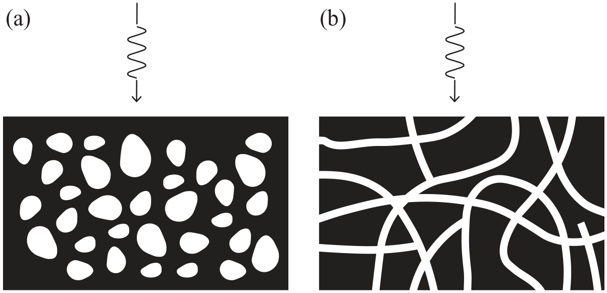
Difference between (a) closed and (b) open porosity mediums.
Pore size distribution
The size of pores in porous materials often varies, 36 see Figure 6. For soils, the size of pores is defined by the texture and roughness of the soil particles. For example, adding perlite and polymer gel to soil can form so-called “meso-pores” (⩾1 mm diameter). This not only improves the acoustic absorption 27 but also expands the frequency range in which sound is absorbed. In nature, meso-pores can be found in for example, forest floors, with a humus layer formed by decaying plant matter and loose soil.8,37 For VGS, due to gravity, leaves are more likely to fall off, and meso-pores are only formed inside the substrate, for example, when the roots expand.
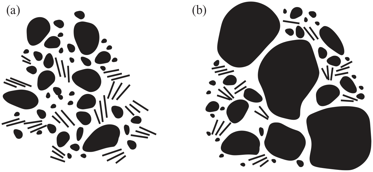
Differences in (a) uniform pore sizes and (b) variable pore sizes.
Substrate thickness
The thickness of the substrate shifts the threshold above which a porous medium absorbs incident sound adequately. This pertains to the rule of thumb that porous absorbers are most effective when placed at a quarter wavelength distance away from a rigid wall. Ingard 38 showed that a wool layer on a rigid structure with a thickness of 50 mm absorbs considerably more sound below 500 Hz than a 25 mm thick layer. For example, considering the 250 Hz octave band, the 50 and 25 mm thick layers have absorption coefficients of α≈0.8 and α≈0.2, respectively. This effect can also be achieved by introducing an air cavity between a rigid wall and a VGS 38 applied the transfer-matrix method to numerically predict for which thickness the substrate, or the combination of substrate, foliage, and air gap, yields most sound absorption when placed on a concrete wall. Attal et al. 39 showed that the optimal thickness depends on the frequency, the impedance of the layers, and the distance between layers and the supporting wall. Thicker layers of porous mediums do not automatically increase the absorption coefficient, as the thickness may also increase the surface impedance of the material.
Air flow resistivity
The air flow resistivity describes the ease with which air can move in and out of a porous medium. 35 For many highly porous and isotropic homogeneous materials, Delany and Bazley 40 (D&B from now on) showed that the acoustic impedance relates to the air flow resistivity. This means that a single value is attributed to a layer or material, assuming a homogenous and isotropic situation. The model is widely used to predict acoustical propagation over outdoor ground surfaces. However, unless it is a controlled setting, natural soils are anisotropic, which means that the porosity varies across the material or substrate. This automatically means that the fitness-of-use of D&B’s model for natural soils is limited. 41 A few years later, Miki 42 refined D&B’s model. Miki showed that his model predicts the acoustic absorption of anisotropic substrates more accurately. 43 Although there are various methods to measure the air flow resistivity, all use an airflow apparatus which creates a steady state or slowly oscillating air flow. Typical average flow resistivity for granular and fibrous materials ranges between 5 and 100 kPa∙s/m2. 34
Tortuosity
A medium’s tortuosity refers to the complexity of the networks formed by the pores. In a porous material with highly interconnected pores, the propagation vector of the acoustic wave changes constantly, resulting in an inertial air flow. The tortuosity refers to the ratio between the material’s thickness and the actual path length of a sound wave reflected by the surfaces of the pores, see Figure 7. 38 The structure factor (k), defined by Kosten and Zwikker, 44 is similar to this parameter.
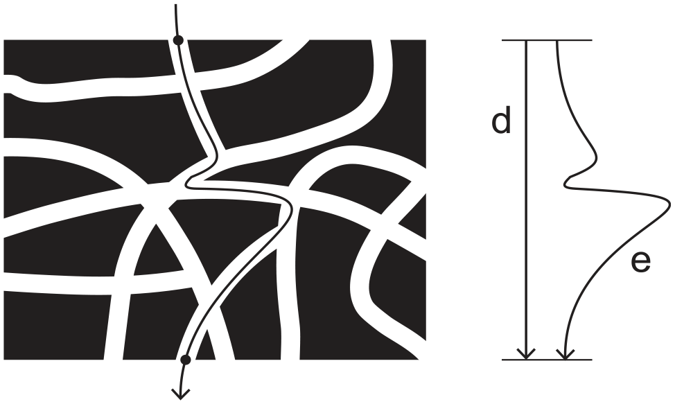
Tortuous propagation, (d) direct path, (e) effective path.
Moisture content
The moisture content in a porous substrate affects its absorption coefficient.27,45 Although water is essential for plants to grow, it clogs the pores and makes absorbent soil particles swell in size, which decreases the acoustic absorption of the material. 45 The extent to which the acoustic absorption drops relates to the degree of saturation. This affects less porous materials disproportionally, as the few pores fill up more easily compared to a material with a fine network of pores.
Horoshenkov et al. 27 identified the influence of moisture on the acoustical properties for two substrate varieties. A low-density substrate made from coconut fibers, perlite and polymer gel was compared with a high-density clay-based soil, see Figure 8. Samples of both substrates were placed in an impedance tube, 100 mm in diameter (1.57 L soil specimen), after which 100 cm3 water was added. The results showed that, for the clay soil, the absorption dropped significantly, up to 1/7th compared to the initial coefficient, see Figure 9. The absorption coefficient flatlined around 0.1 for the frequency range examined in their study (100–1500 Hz). Although the absorption coefficient also decreased for the coconut-perlite-composite, the effects were less dramatic (2/3rd compared to the initial value) and only affected frequencies above 200 Hz. The large differences between both substrates were attributed to capillary forces, which are greater in the small pores of the low-permeable clay-based soil (40–60 μm in diameter), which decreases the material’s absorption drastically. Additionally, the polymer gel particles in the low-density substrate absorbed a large portion of the moisture, which kept clear the pores which were deeper inside the material.
Difference between (a) low-density coir substrate and (b) high-density clay-based soil.
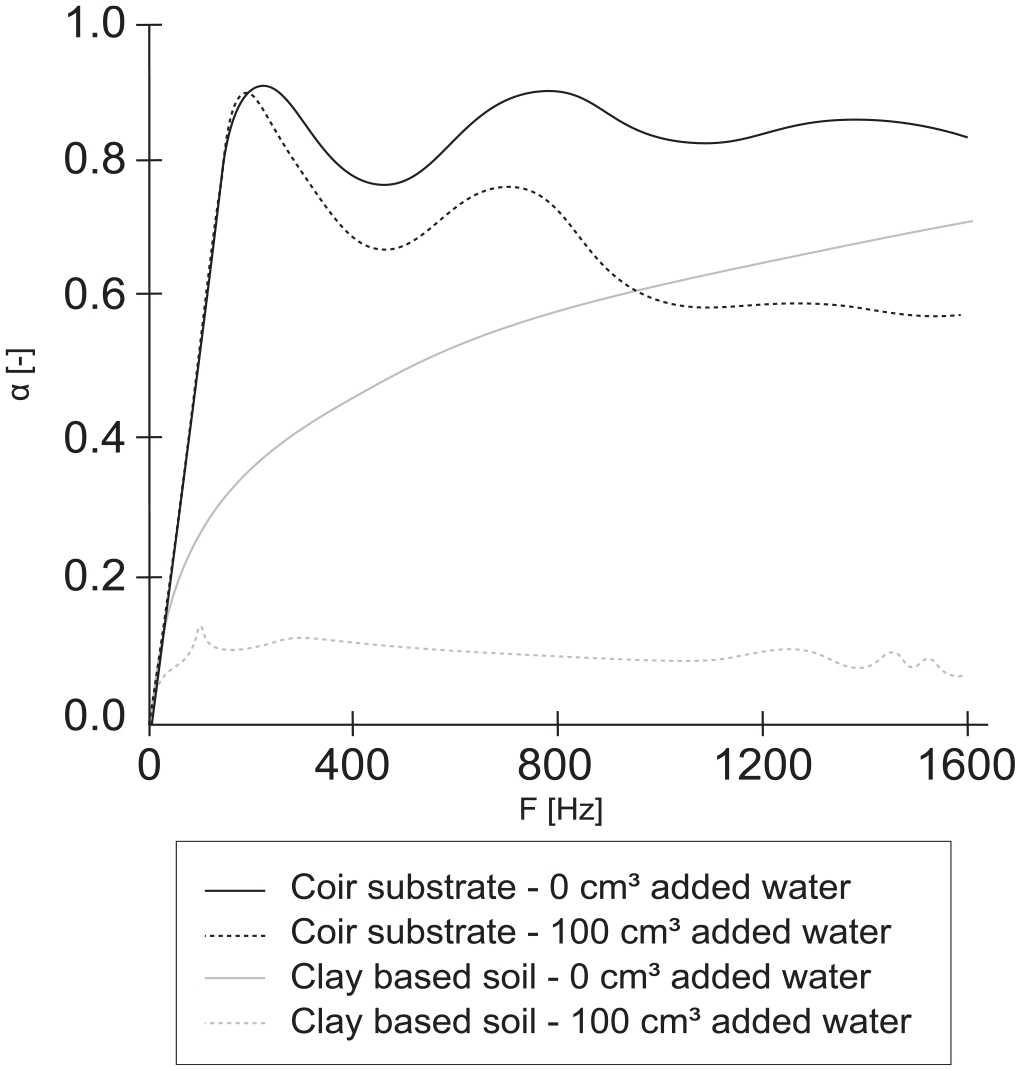
Effect of moisture on substrate acoustic absorption as measured by Horoshenkov et al. 27
A similar comparison was undertaken by Van Renterghem and Botteldooren, 45 who studied the influence of rainfall on the acoustic properties of a green roof in an outdoor setting. The green roof comprised a mineral substrate, XF200 of 70 mm thick, covered with various sedum species (cover ratio 65%). The sound source was placed on street level while the receiver was placed on top of the green roof, which was elevated about 6 m. The sound pressure levels for dry stratum were almost 10 dB lower compared to a nearly soaked roof. The study also found that sound diffracted differently on roofs with a greater moisture content in the frequency range of 250–1250 Hz.
Sound absorption by vegetation
In literature, vegetation not only refers to the leaves (i.e. foliage) but also encompasses stems, branches, soil and air volumes(s) which are formed in between the leaves. 46 The leaves can be considered as solid membranes with little sound absorbing qualities. However, the combined texture of a vegetation layer and the combination of membranes and air volumes absorb and scatter incident sound. 47
Vegetation attenuates sound in three ways. First, air which sits trapped in the foliage can be considered as a porous medium inducing viscous-thermal damping. 35 Second, depending on the plant species, when hit by a sound wave, individual leaves may oscillate, which leads to local sound absorption. This effect occurs for a wide range of frequencies, depending on the wavelength and the dimensions of the leaves. 20 High frequency sound is often mainly a problem close to the sound source. At a greater distance from the source, the higher frequencies are absorbed in the atmosphere, while, as said in the introduction, the peak intensity of car traffic noise lies around 1000 Hz. Third, the plant layer can be considered as an array of reflectors with randomly sized and oriented leaves. 48 This leads to local scattering and destructive interference. The mechanisms behind leaf vibrations, visco-thermal absorption and scattering are discussed in more depth in the following sections.
Visco-thermal absorption
Like the substrate, the vegetation layer can be considered as a (uniform) porous medium 34 with a flow resistivity, porosity, tortuosity and thickness. The visco-thermal properties of a plant layer are determined by various non-acoustic parameters, 34 of which the leaf area density and dominant directional angle of the leaves are the key indicators. 43
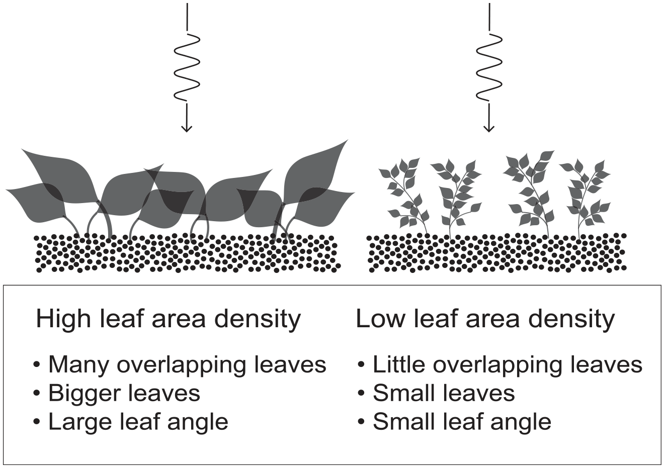
Leaf area density
The foliage density is defined as the ratio between the total leaf area (in m2) of a plant and an imaginary cylindrical volume (in m3) drawn around the plant. This measure, the leaf area density (Av), relates to the air flow resistivity (σ) of the porous vegetation layer. A denser foliage absorbs more incident sound energy and for a wider range of frequencies.43,49
D’Alessandro et al. 34 developed a method to calculate the mean leaf area by placing leaf cuttings on a horizontal plate with reference rulers, after which a high-resolution picture was taken and the pixels falling inside a box with fixed dimensions were counted in software for graphic editing.
According to Horoshenkov et al., 43 measuring the flow resistivity of a plant sample using ISO 9053 yields results too unreliable, as the pressure differences across the plant layer are too weak to measure. Instead, they specified the absorption coefficient for several plant species via a quasi-heuristic approach using a standard optimization algorithm. The standard optimization algorithm computes non-acoustical values for the flow resistivity, tortuosity, and porosity for a plant specimen. Practically, this means that the flow resistivity of the plant layer is based on the computed leaf area density and the dominant leaf angle. 43 Horoshenkov et al. 43 showed that the air flow resistivity increases exponentially for an increase in leaf area density.
Orientation of the leaves
The dominant direction angle of the leaves (θ) is the mean difference between a leaf’s petiole and the stem (in degrees), 43 see Figure 10. This angle is a key for the tortuosity of the plant layer. A greater leaf angle extends the length of the propagation path, and thus a greater tortuosity. Maximum tortuosity is reached for leaves protruding perpendicularly to the direction of the wave front of the sound wave.
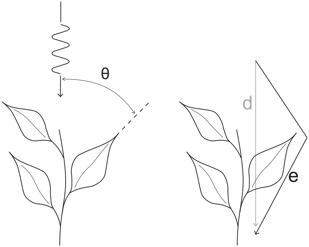
Dominant angle of leaf orientation (θ) and its relation to tortuosity with (d) being the direct path and (e) the effective path of the sound propagation.
Leaf vibrations
When the wavelength of the sound is similar to the size of a leaf, a leaf will vibrate at the specific (resonant) frequency. 50 In this process, sound energy is transferred to heat. 51 This phenomenon was studied by Martens and Michelsen, 20 who showed that leaves vibrate for a wide range of frequencies. They examined plate vibrations in plants, by comparing a variety of leaves (privet, birch, hazel, and oak) with laser vibrometry. In this method, the leaves were not exposed to a mechanical load, which means that the resonance frequency remained unchanged. The results showed that leaves behave as linear mechanical systems resonating with a velocity which ranges between 1 × 10⁻⁵ and 3 × 10⁻⁴ m/s. This is 1–3 orders of magnitude slower than the velocity of air particles. Although the sound attenuation induced by a single leaf is small, a plant layer consists of a multitude of leaves. In a follow study in which leaves were modeled as aluminum plates it was found that the sound attenuation peaked around 4000 Hz (λ = 80 mm) which was similar to the dimensions of the ivy leaves used in the study (see Figure 11). 52
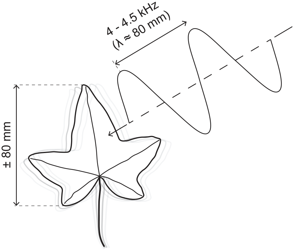
Ivy leaf vibration as mentioned by Martens et al. 52
A similar study was carried out by Tang et al., 51 who placed accelerometers at various positions atop the leaves. The study showed that leaves resonate at different frequencies following two distinctive patterns, clustered around specific frequencies. For the first cluster of resonant frequencies (between 2.5 and 3 kHz), the leaves resonated along the direction of the petiole. For the second cluster of resonant frequencies (between 8 and 10 kHz), the leaves resonated along the width of the leaf surface for the widest span of the leaf. This means that a leaf has several resonating modes. These findings show that a leaf’s resonant frequencies depend on the dimensions of the leaves (width, length) and not on their shape.
Pérez et al. 6 and Martens et al. 52 both argued that the level of resonance is influenced by the mass of the plant. From an acoustic perspective, this means it is recommended to select plant species with heavy leaves and a dense foliage. However, this is mainly an issue if plants are used to abate high pitched sounds.
Predicting visco-thermal absorption
The visco-thermal absorption in soil-plant systems can be predicted by an equivalent fluid model (EFM). 43 In that model, both the soil and the plant layers are simplified as porous mediums. The models by D&B and Miki, which were mentioned earlier, can be applied in an EFM. For example, Horoshenkov et al. 43 used the model by Miki 42 to determine the frequency-dependent absorption coefficient of plant-soil systems. Moreover, D’Alessandro et al. 34 found a good fit between Miki’s model and impedance tube measurements of plant samples. For example, in their study, the error for fern specimens ranged between 0% and 0.9%. The error was slightly greater for samples of baby tear (3.7%–4.4%). Figure 12 shows a schematization of the effect of plant morphology on leaf area density.
Effect of plant morphology on leaf area density.
Scattering and destructive interference
The shape and texture of the plant layer scatters incident sound waves. This means that sound scatters in various directions without a physical reduction of the total sound energy (i.e. absorption). Mathematically, scattering forms the imaginary component of acoustic impedance. 51 Scattering impedes the free propagation of sound, which may lead to destructive interference for higher frequencies. 34 Also, scattering alters the direction and energy distribution of the sound field, which may reduce the sound level locally, for example, near the observer.
Destructive interference is caused by direct and reflected sound waves cancelling out each other (see e.g. Ingard 38 ). The phenomenon can be caused by path length differences between direct and reflected waves. Additionally, the interaction between a porous medium and a wave may cause a phase delay yielding a similar effect. The frequency above which local destructive interferences become key for a plant layer’s sound attenuating qualities depend on leaf size. Bigger leaves will lead to a lower frequency threshold and vice versa. However, for vertical greenery, it will be difficult to predict where and when interference will take place, as it is very dependent on wave lengths, leaf size, surface texture and the length of the propagation path.
Sound absorption by plant-soil systems
Asdrubali 33 compared the acoustic effects of several plant species, including ferns, baby tears, and ivy on a fibrous substrate, in both an impedance tube and a reverberation chamber. The study showed that, for plant-soil-systems, most acoustic absorption comes from the substrate. For example, in comparison to a bare substrate, the absorption coefficient of a soil-plant system covered with samples of dense fern was about 25% higher for frequencies between 800 and 1600 Hz.
Ding et al. 8 researched the effect of leaf vibrations when added atop a porous medium. In the study, melamine foam was used as an artificial substrate in an impedance tube. Atop the foam, circular shaped leaf cuttings of several species were placed. The leaf species assessed were Japanese andromeda, scarlet wonder, primrose, and Corsican Hellebore. Based on measurements and a numerical model, Ding et al. 8 showed that, compared to an uncovered substrate, the combination of plants and substrate increased the acoustic absorption for frequencies between 500 and 2000 Hz, while no effects were found for frequencies lower than 250 Hz, and slightly lower absorption for frequencies ⩾2000 Hz.
Horoshenkov et al. 43 studied the acoustic absorption of different plant and substrate varieties. The plant species, schematized in Figure 13, varied in average leaf area, the number of leaves on the specimen and the dominant leaf angle. Like Ding et al., 8 Horoshenkov et al. 43 adopted a mixed approach combining impedance tube measurements and a numerical model (i.e. based on Miki’s model). They found that the winter primrose yielded the highest acoustic absorption. This plant species had the greatest leaf area density (Av = 135.6 m−1) and the greatest leaf angle (θf = 72±15°). Combining a layer of winter primroses with a porous coir-based substrate increased the absorption coefficient by roughly 80% for frequencies below 400 Hz and between 15% and 20% for frequencies above 800 Hz. The study showed that all plant specimens increased the acoustic absorption of the substrate.
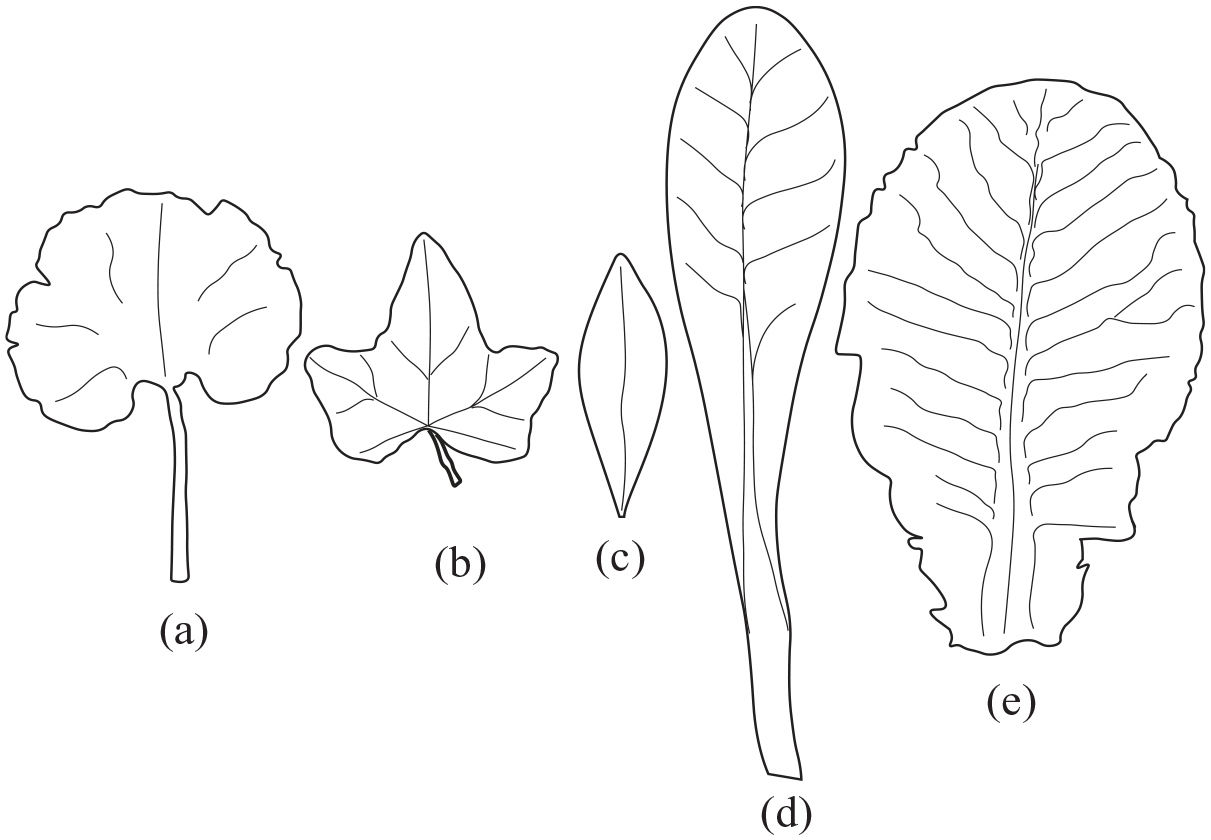
Plant species by Horoshenkov et al. 43 (a) Geranium, (b), Ivy, (c) Japanese Andromeda, (d) Summer Primrose, (e) Winter Primrose.
Wong et al. 53 examined the acoustic properties of VGS in a reverberation room. In this study, a wooden frame was built and pots with Boston ferns were put atop the frame. The coverage density of ferns was varied (100%, 71%, and 43%). They found that the maximum coverage reduced the room’s reverberation time substantially, especially for frequencies between 200 and 1000 Hz. Similar to other studies,8,33,43 Wong et al. 53 found poor acoustic absorption for frequencies below 250 Hz. Above 1000 Hz, the 100% coverage yielded α≈0.5, the 71% coverage yielded α≈0.4 and the 43% coverage yielded α≈0.27.
D’Alessandro et al. 34 studied the acoustic absorption of Boston fern and baby tears in combination with a porous coconut fiber soil, using impedance tube measurements. The results showed that the absorption coefficient peaks at various frequencies. The first peak appeared around 400 Hz leading to an absorption coefficient of α≈0.7. After a small dip, the absorption increases again up to coefficients α≈0.9 for frequencies ⩾1200 Hz. Without the substrate, the absorption coefficient for ferns remained below 0.3. These findings confirm that the substrate absorbs most of the sound energy in a soil-plant system.
Smyrnova et al. 46 also studied the acoustic absorption of various plant species, that is, pancy, primrose, and buxus, by using a P-U probe in a reverberation chamber. A P-U probe measures both the acoustic pressure and particle velocity, which together define the sound intensity. Plants were potted and put in a matrix on a flat floor. In contrast to the studies which were mentioned earlier, Smyrnova et al. 46 only focused on the reverberation time. The reverberation time decreased for all plant species, especially for frequencies ⩾250 Hz. Densely planted buxus (16 pots/m2) showed the highest acoustic absorption in this study.
Thomazelli et al. 54 assessed the sound absorption of a geotextile living wall system carrying a coconut-fiber substrate covered with turtle vine, in a reverberation room. With a porosity of 87%, the porosity of a coconut-fiber substrate approaches the porosity of mineral wools. In the laboratory experiment, the geotextile bags were placed horizontally, both with and without substrate and vegetation. The system with substrates and plants showed the shortest reverberation time and the highest absorption coefficient (near 1 for frequencies ⩾1000 Hz).
As mentioned before, Attal et al. 39 used the transfer-matrix method to assess the optimal dimensions of VGS. The performance was expressed in dB return loss compared to a concrete wall. For both coir dust and perlite, an optimal foliage thickness of 10 cm was found, leading to a return loss ⩾10 dB for frequencies between approximately 300 and 800 Hz. The study also showed that return losses are substantially greater for systems comprising of a substrate and plant layer. For frequencies between approximately 300 and 800 Hz, return losses increased by roughly 7 dB if a plant layer of 10 cm was added on top of a substrate, for both coir dust and perlite. The scientists used Japanese Spindl for the plant layer.
Effect of VGS configuration on acoustics
The efficacy of green walls depends on the position of the greenery relative to the wall and the design of the vertical greening system. Examples of these design parameters are the system’s permeability and whether an air cavity is kept behind the VGS. This section presents literature on the position and design of vertical greening systems.
Sound insulation and VGS
Wong et al. 53 compared the acoustic attenuation of eight in situ VGS. The eight variants in the study had different substrate thickness, plant height and supporting system (a mesh or shelved boxes), representing different VGS types as depicted in Figure 1. The acoustic properties were studied by comparing the insertion loss of a wall with and without vertical greening. Insertion loss (IL) is determined by subtracting the sound pressure level measured before and after an intervention (e.g. a wall or noise barrier). VGS containing plants with small leaves and large permeable gaps yielded no or little effect, showing a maximum IL up to 4 dB for the 800 Hz one-third octave band. On the contrary, systems with the substrate sitting in box-shaped containers or with broad-leaved and densely packed plants led to much higher ILs. The IL peaked around 8 dB (630 Hz 1/3-octave band) and 9 (4000 Hz 1/3-octave band). The study also found local dips and peaks in the insertion loss spectra which required more research, and that a low permeability was key for a great IL.
Depending on the system, vertical greening also adds extra acoustic insulation to a building or wall. According to Pérez et al., 6 small gaps and cavities, for example, between plant boxes but also between acoustic bridges connecting the vertical greening system with the supporting wall, can reduce the acoustic insulation of the system.
Air cavities behind VGS and VGS as metamaterials
As mentioned before, air gaps between a rigid wall and a VGS can improve the absorption of lower frequencies due to the quarter wave transfer effect, 55 coinciding with the position of the highest particle velocity. 56 Davis et al. 7 studied the acoustic effects of air cavities varying in depth (5 and 10 cm) placed behind vertical greening modules, in a reverberation room. Results showed that adding air cavities increased the level of absorption for lower frequencies. Thomazelli et al. 54 found a similar effect for a gap of 20 cm behind a geotextile VGS with a coconut coir-based substrate, in-situ. Moreover, Wong et al. 53 showed that a cavity behind a VGS led to a greater IL (3 dB) around 150 Hz, which was absent in the results for VGS without air cavities. Also Chang and Chang, 57 based on tests in a reverberation room, showed that the support structure of a VGS can help improve the sound absorption in the frequency range below 1000 Hz. Panels made from of a wood-plastic composite with a small air space and perforations placed behind the VGS increased the sound absorption coefficient especially between 160 and 400 Hz. Furthermore, Lau et al., 58 using simulations and impedance tube measurements, showed that the addition of acoustic metamaterials inside the VGS could also enhance the sound absorption properties in the lower frequencies. The air layer can be considered as a separate substrate with a specific impedance. Attal et al. 55 showed that increasing the air gap shifts the frequency of the (first) absorption peak, but also weakens the absorption coefficient of the peak.
Position of VGS on facades
To reduce traffic noise, Van Renterghem et al. 59 used a numerical model to study the impact of building envelope greening in street canyons, see Figure 14. In the study, 21 scenarios were compared for two adjacent canyons. Sound levels in the receiver canyon were lowest when the greening was mounted vertically on ledges below the roof tops in the source canyon. The study also found good results for scenarios with low vertical screens clad with greenery on the roof’s edges. Such screens add extra edge diffraction in combination with sound absorption and are most effective when placed on both sides of the roof (facing toward the source and receiver canyons). Moreover, the study showed that an increase of vegetation in the receiver canyon results in lower sound levels. Although green roofs increase the level of absorption, the shape of the roof is the most important indicator for sound propagation between source and receiver canyons. Van Renterghem et al. 59 concluded that the number of diffraction points, sharp edges, and the slope of the roof are key for diffraction and friction between sound and material influencing the amount of sound energy that reaches a receiver canyon.
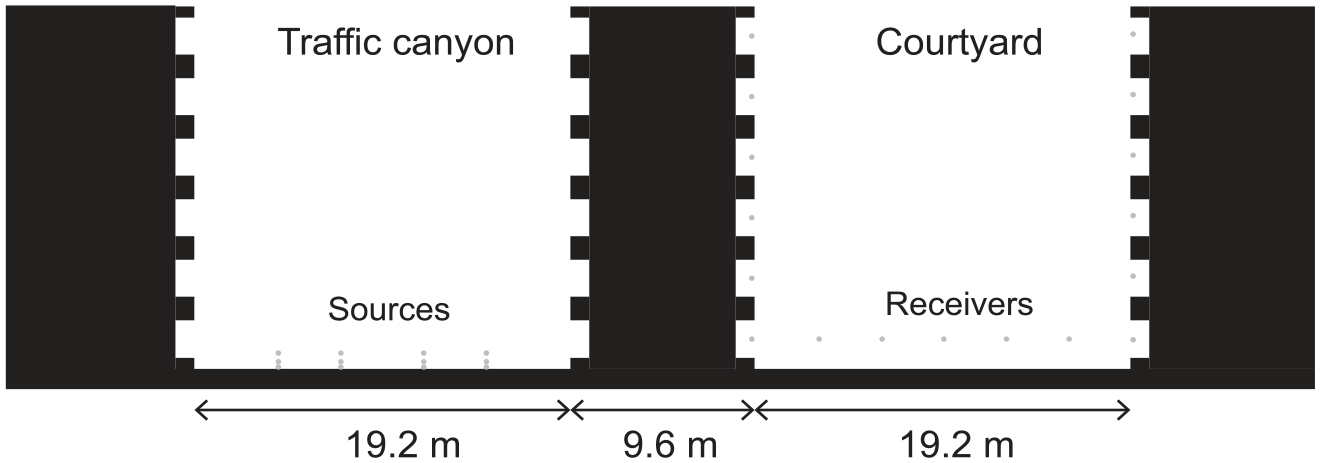
Urban canyon and courtyard model used in the research of Van Renterghem et al. 59
Results from a similar numerical study by Guillaume et al. 60 confirmed the findings from the study by Van Renterghem et al., 59 showing that, to reduce sound propagation between canyons, vertical greening is most effective when mounted higher up on the walls in the source canyon.
For the absorption coefficient of a surface consisting of patches of vertical greenery mounted on the supporting surface, it does not make a difference where the patches are placed. For example, Davis et al. 7 compared the results for two types of green walls in a reverberation room, one with the plants clustered together and one with the plants dispersed over the surface. Results for both scenarios were similar.
Discussion
Comparison of studies
Based on the studies in the previous section, the first observation which can be drawn is that VGS act as porous absorbers. This means that VGS are well equipped to absorb mid- and high frequency sound but absorb low frequency sound poorly. This is clearly visible in Figure 15, which visually combines the absorption coefficients from the various studies underlying the literature review. The figure shows that, if studies report about results for frequencies lower than 125 Hz, absorption coefficients are very low. This is in general the case for frequencies below 250 Hz, mainly based on studies containing results from impedance tube and reverberation room measurements. Dips in the absorption coefficient were found for specific frequencies in the higher frequency domain, as a result of various local and irregular interferences in the vegetation and/or substrate layer.
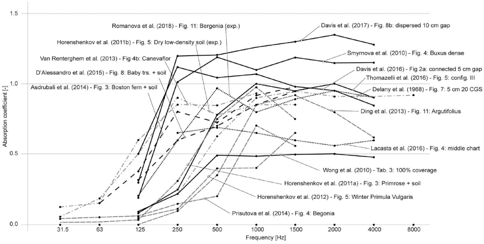
A selection of absorption coefficient results. Solid black = reverberation chamber (densely planted systems), gray dashed = impedance tube (plant-soil), gray dash-dot = impedance tube (substrates), and black dashed = in-situ measurements.
Although the overall trend is similar for the various graphs, they differ in terms of the tipping frequency from which the absorption coefficient starts to climb and the magnitude of the absorption coefficients in the higher frequency range. To scrutinize these differences, the graphs were grouped according to the research method used per study. The different groups are marked by different line styles, as can be read in the caption below Figure 15. Figure 15 shows that absorption coefficients for studies in which a reverberation chamber was used, are clearly higher than other studies since the random incidence in such a setup deals with edge scattering. Results from studies using an impedance tub report lower absorption coefficients compared to other methods based on random incidence, which is well described in literature, see for example Cox and D’antonio. 61 For larger sample sizes, the interaction between the individual leaves becomes increasingly more complex, inducing more destructive interference and scattering than a small patch of vegetation. Aside from differences which depend on the research method, variations between results might have been caused by the variety of plant species and/or substrates. The frequency range of results also varies across studies, which makes it more difficult to compare results.
Figure 16(a) shows that the most common species used in research were ivy, Boston fern and primrose. Although these species were most popular in research, these species are not necessarily the best choices. Based on a cross-comparison of the literature reviewed for this paper, studies using leaves with a large leaf area and/or referring to leaves pointing perpendicularly in the direction of the incident sound wave, create a dense and packed plant canopy. Consequently, incident sound waves are obstructed from moving freely through the plant layer. The number of leaves on a plant is not always a good indicator for the level of acoustic absorption, as shown by the Boston fern, which leaves are relatively small. Conversely, the Primrose, which has relatively large leaves and sits densely packed with the dominant angle of the leaves almost perpendicular to the direction of the incident sound, yields a high level of acoustic absorption. Depending on the season, a plant’s acoustic performance may vary throughout the year. The studies do not comment on the “forest floor effect,” referring to absorption by a humus layer of decomposing plant, also applies for VGS. If it does, the effect will be very slim.
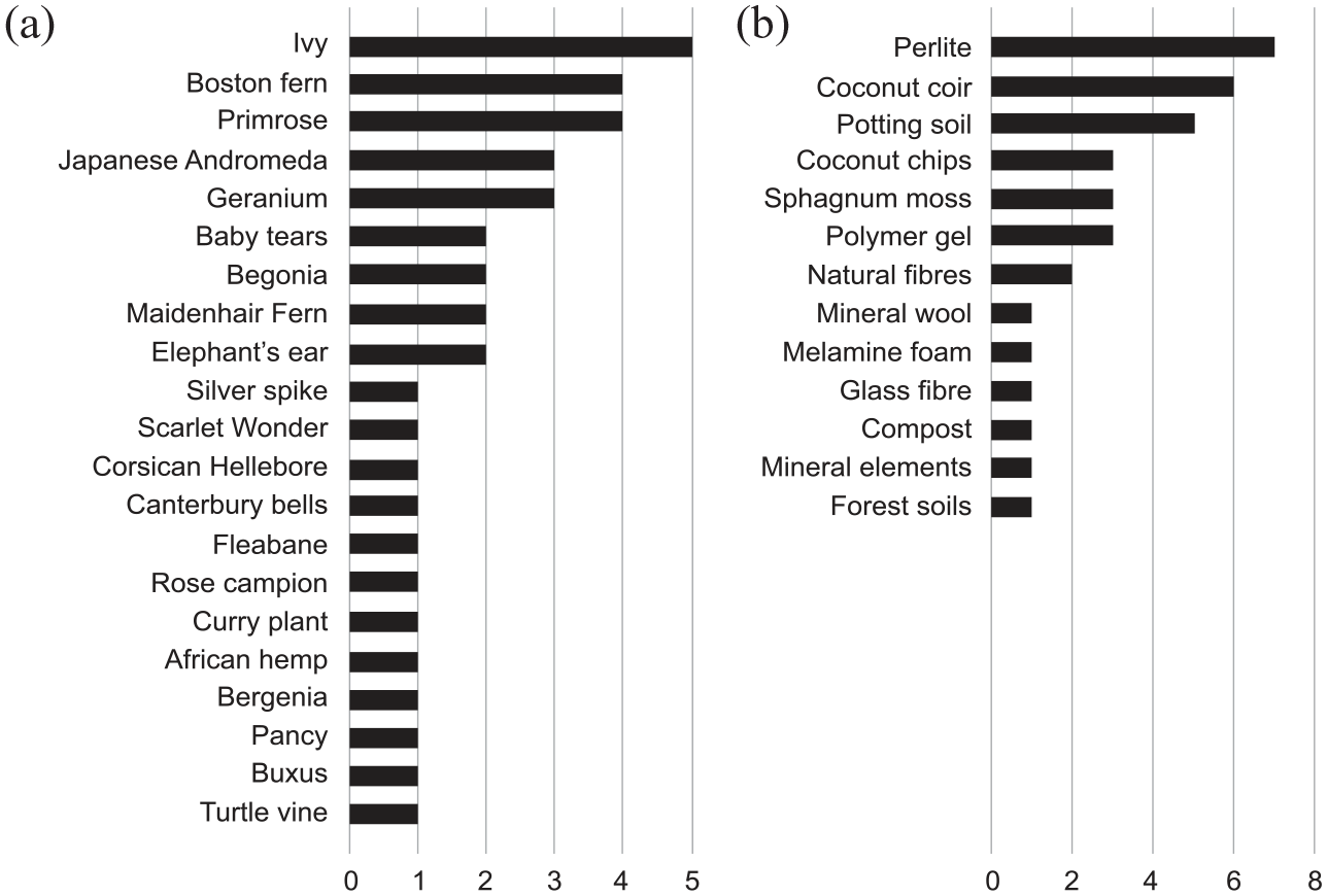
Most recurring (a) vegetation species and (b) substrate compositions.
VGS come in different shapes, ranging from climber plants mounted on a supporting mesh to hydroponic living wall systems based on geotextile bags or plastic containers. This makes it difficult to compare systems one to one. However, in general, the living wall systems, having porous substrates distributed over a large surface area, lead to more absorption. To improve the absorption of low(er) frequency sound, that is, frequencies <250 Hz, several studies suggested a cavity between the supporting wall and the substrate.
Alongside regular potting soil with optional perlite and polymer gel, a notable recurring substrate composition was the artificial substrate that consists out of coconut coir, see Figure 16(b). Coir is a natural fiber made from coconut shell and commonly used in horticulture. Due to its lightweight and porous properties, the acoustic absorption of coir is relatively high. Perlite, comprising small balls formed by expanded volcanic glass, is added to substrates to counter soil compaction. Perlite is a highly airy material which increases the porosity and pore size distribution in soils. Polymer gel particles, or vermiculate pearls, consist of hydrophile particles which reduce the moisture content. As the pearls trap the water particles, droplets are prevented from clogging pores or tubes within the soil sustaining the porosity of the substrate. Although the thickness of the substrate varies between studies, the literature shows that a thickness of ⩾50 mm absorbs well for ⩾1000 Hz. For frequencies <1000 Hz, a thicker substrate can help. To reduce the amount of sound traveling from a source canyon to adjacent courtyards or streets, VGS are more effective when mounted just below the roof edge in the source canyons or when covering as much as possible of the vertical surfaces in the receiver canyons.
Methodological challenges
Based on the literature review, various challenges were identified with respect to research methods used to assess the acoustic properties of VGS.
The first challenge relates to measuring long term in-situ effects. In-situ measurements are relevant to scrutinize the in-situ effects of large walls with vegetation for different seasons throughout the year. 62 To the authors best knowledge, there is no uniform standard for in-situ measurements, which makes it difficult the compare results between studies. 63
The second challenge relates to controlled experiments in laboratories. Limited space, time (i.e. to study aging and seasonal effects) and funding pose an obstacle to complying with the minimum size of 10 m2 for research on VGS in laboratories or reverberation rooms, as recommended by ISO 354. This means that, often, studies use smaller samples, which increases scattering near surfaces covered with vegetation, leading to less accurate results. 62 Prisutova et al. 63 argue that standard impedance tubes, as defined in ISO 10543-2, are too small to accurately measure the acoustic absorption of vegetation for a broad frequency spectrum.
To overcome these challenges, various alternative solutions have been put forward by researchers. For example, Lacasta et al. 62 tested an alternative method to detect ground reflections in in-situ measurements. Two microphones are placed equally mirrored around the omni-directional source. One microphone is placed in between the source and VGS sample. Ground reflections can be detected in the signal by placing one microphone in-between the VGS and an omni-directional sound source and a second microphone further away from the source. Both microphones are exposed to the same ground reflections, but as the signal reflected from the sample arrives at a slightly later moment in time the difference can be determined. Tang et al. 64 also used an in-situ two microphone set-up, even though it remains unclear from the paper how the microphones were placed and how the results were analyzed regarding reflections. Furthermore, they only looked at 2000 Hz.
Romanova et al. 50 also developed an alternative method to adjust in-situ measurements for ground effects and edge scattering. The researchers used equipment that records and/or transmits a highly focused beam formed by a parametric transducer. This means that only a small, yet delineated, area is exposed to sound (90% within ±10–12° in the horizontal plane). Reflections measured by directional microphones can only originate from the sample ruling out the influence of ambient noise, edge scattering and ground reflections. For frequencies between 400 and 1250 Hz, the researchers managed to create a high signal-to-noise ratio using signal deconvolution comparable to impedance tube measurements. The results showed dips in the absorption curves for specific frequencies. Since the intensity probe used in this study is very sensitive to local amplifications, these dips might have been caused by local sound interference, for example, induced by leaf vibrations. Romanova et al. 50 attributed the dips in the absorption coefficient to resonances in the modular living wall containers depending on the container dimensions and depth of the system.
A different approach was coined by Prisutova et al. 63 using a large impedance tube (0.3 m/0.3 m/4.15 m). Inside the tube, an adjustable microphone measured the sound pressure at 51 positions. Measurements were compared with numerical (EFM) calculations, showing a good fit between measurements and calculations for frequencies ⩽572 Hz. This wavelength corresponds to the dimensions of the 0.3 m × 0.3 m cross-section. For higher frequencies, modal reflections become more complex due to multiple scattering effects, increasing the probability that the numerical model overpredicts the absorption coefficient. This example shows that more research on EFM and acoustic absorption is needed. Also, since several combinations of input variables compute similar results, caution is necessary before conclusions can be drawn from numerical calculations. 34
Conclusions
In this paper, a literature review on the acoustic absorption of vertical greening systems (VGS) was presented. The main findings can be summarized as follows:
VGS act as porous absorbers, mainly absorbing sound for frequencies ⩾200 Hz.
The effective air flow resistivity of the substrate and vegetation controls the absorption of incident sound. For the substrate, the flow resistivity depends on the open porosity (connections between pores), pore size distribution (variation in pore sizes) and tortuosity (the level of curvature and length of the pores/tubes). For the plant layer, the air flow resistivity depends on the leaf area density and the dominant leaf angle.
The geometry of the plant layer, formed by the leaves, scatters incident sound, which may lead to local sound abatement.
A higher moisture content of the substrate affects the porosity of the soil and reduces acoustic absorption.
Materials with a high porosity and high pore size distribution, like coconut coir, are recommended for the substrate. Adding perlite and vermiculate particles keeps the soil porous, as it prevents soil compaction and water clogging inside the pores.
The optimal thickness of the substrate and plant layer in a VGS cab be predicted numerically based on equivalent fluid models or the transfer-matrix method.
Adding an air cavity behind the system or increasing the substrate thickness may improve the absorption of low frequency sound.
For the design of VGS, the following recommendations are made in respect to acoustic absorption:
Substrate as porous as possible, with a wider pore size distribution
Add perlite to the substrate to keep the pores open when the substrate gets wet
Plants must be placed as densely as possible
Plant leaves must be as broad as possible
Plant leaf area density as great as possible
Leave angle as close as 90° to the wave front of the incident sound
Use well-developed evergreen plants
Place air-cavity behind system (size can be tuned to specific frequency)
No gaps in vertical vegetation canopy through which sound can transmit
Damping vertical greening system connections, to reduce the transmission of vibrations to the façade structure
Determine the optimal thickness of layers numerically based on the impedance of the individual layers.
Footnotes
Declaration of conflicting interests
The author(s) declared no potential conflicts of interest with respect to the research, authorship, and/or publication of this article.
Funding
The author(s) received no financial support for the research, authorship, and/or publication of this article.