
Abstract
In order to attain an expected sound insulation in buildings, it is necessary to employ appropriated constructive solutions, but it is also fundamental to guarantee compatibility with other involved design professional fields, proper detailing of solutions and correct on site mounting. A solution with a predicted high acoustic performance may result in failure if there is no proper interconnection between other design professional areas or if execution mistakes occur, even if of very small dimension. The main objective of this technical paper is to analyse the influence of defects that typically occur in buildings, located in Portugal, resulting in very poor airborne or impact sound insulation performance. The chosen situations refer to buildings with heavyweight concrete structure, where small construction defects occurred and/or wrong decisions were taken, ending up with a large reduction on the final acoustic performance. Some of these errors, given their small size or because they occurred in hidden zones, easily passed unnoticed, on site. The defects here addressed in what refers to airborne sound insulation are related with execution of double masonry hollow brick walls, sound bridges in acoustic suspended ceilings, passage of ventilation or sewage pipes, inappropriate installation of acoustic doors, shutter boxes or windows. As for impact sound insulation, the presence of rigid connections is the main focus of the characterisation here performed.
Introduction
In general, the acoustic protection of buildings, as a way of ensuring adequate acoustic comfort, can be achieved through acting according to four fields of building acoustics1–3: airborne sound insulation; impact sound insulation; inner acoustic conditioning and minimisation of noise produced by building service equipment and facilities.
In the case of airborne sound insulation, there are two situations that are important to distinguish: façade insulation and insulation between interior compartments. In the first case, and for most buildings, sound insulation depends essentially on acoustic performance of the window, mainly related with frame and glass and is also related to the presence of ventilation grids and shutter boxes. In the second case, sound insulation in contiguous rooms depends not only on the acoustic behaviour provided by direct separation element, but also on the transmission occurring through surrounding elements of each compartment. 4 In general, the increase in sound insulation regarding direct path can be attained, among other ways, by increasing the mass and/or creating elements with multiple layers, without rigid connections to each other. On the other hand, the reduction of flanking transmissions can be achieved by breaking the continuity between the flanking elements, but often this type of action is not feasible, making more difficult the control of this transmission path.5,6 In both cases, the existence of possible ‘sound bridges’, such as small slits, imbedded sockets and crossing ducts, can strongly compromise the final result, often leading to non-compliance with insulation requirements.7–10
In the impact sound insulation, from a floor to the neighbouring spaces, transmission occurs by flanking paths, through adjacent elements and by direct path, when the impact floor is above the receiving compartment. 11 In general, obtaining proper impact sound insulation can be achieved through two distinct types of solutions: flexible floor coverings or rigid floor coverings applied on a resilient layer, namely floating screeds and floating floors. Between these solutions, the mounting of a floating screed, under the floor covering, is the one that offers more advantages, for employing in new constructions and does not influence the type of lining to be employed. However, in the majority of situations, the performance of these screeds is very weak, mainly due to the existence of construction defects. These, usually of very small size, as for example, the case of rigid connections generated by the application of cement glue on the bonding of the floor covering, are quite common in ceramic or stone linings.
In order to quantify the airborne or impact sound insulation of buildings, in situ measurements are usually performed. Different results are often obtained for similar structures, which may be due to observable differences in the elements, the measurement procedure or the standard of workmanship used. Variation due to observable differences in the structures can often be identified and eliminated. Variation due to the measurement procedure can be minimised by using an identical experimental procedure and appropriated equipment for all measurements. The variation in performance of built structures due to workmanship remains a factor of considerable practical importance. Craik and Steel12,13 investigated on the influence of workmanship in monolithic floors. They measured an average variation in the sound transmission loss and structure born sound transmission of concrete floors due to workmanship corresponding to a standard deviation of about 2 dB. Trevathan and Pearse 14 applied a similar procedure to that employed by Craik et al. to evaluate the influence of workmanship in the variation in sound transmission loss for the steel framed walls in the building and encountered a standard deviation of 1.1 dB on average.
On the other hand, when using an accurate prediction model (with proper selection of constructive solutions and considering all the transmission phenomena involved4,11), large differences between expected performance and measurements may also be found. These differences usually result from defects induced by an incorrect construction procedure and wrong decisions taken during execution. 7 Labres et al. 15 evaluated the influence of some defects in single brick walls to which constructive flaws were induced: gap inserted above wall; no filling of vertical joints and installation of electrical junction boxes. In comparison with the reference masonry brick wall, reductions of 1 dB in airborne sound insulation were found for the samples with gaps above the wall and 2 dB for the walls with no vertical mortar filling. As for the panels with installations, this reduction reached 3 dB for samples with electrical junction boxes, two on each face. Besides these works, as far as the authors know, a detailed analysis on the influence of a set of current acoustic defects has not yet been performed.
As in other fields, but with relevance in sound insulation performance, obtaining quality in construction requires also a deep knowledge of the materials used and construction technologies. A constructive solution with an expected high acoustic performance can result in a complete failure, if some execution defects are performed, even if of very small size, which usually pass unnoticed during workmanship. 16
It should also be noted that, in addition to the construction process, it is essential to link acoustic design with the other involved professional fields, namely architecture, stability and technical installations, in particular water, sewage and HVAC systems.
The main objective of this work is to analyse the influence of defects that typically occur in buildings, in Portugal, resulting in very poor airborne or impact sound insulation performance. The defects here considered are the result of errors, which are related to the construction processes of new buildings and may induce large differences between predictions and measurements. It is important to bear in mind that there are other pathologies which occur in older buildings such as cracking or degradation of materials, resulting, for example, from moisture or structure settlements and may also reduce the acoustic performance, however these are not within the scope of the present paper.
Analysis is performed for situations with standard sound insulation performances (according to the Portuguese acoustic code 17 ), while other refer to situations with expected high acoustic performance. With this aim, several case studies were selected from existing buildings employing heavyweight concrete structure. Then, measurements are carried out, to quantify the final sound insulation performance. In most cases, the defect is removed, to evaluate the performance without its presence, while in some other cases, measurements are compared with predictions using methods prescribed in ISO standards.
This paper is organised as follows: section 2.1 describes the main defects that are here discussed, and the case studies referring to buildings where these defects were assessed; section 2.2 describes the constructive solutions employed while in section 2.3 the experimental procedure is addressed; section 3 displays the frequency domain curves regarding airborne sound insulation, façade sound insulation and impact sound insulation and single number quantities, for the analysed situations, while section 5 provides a discussion on the results obtained.
Materials and methods
This paper aims to analyse the great impact that small construction defects resulting from wrong constructive processes have on final performance of buildings (in some cases with deviations greater than 10 dB). The method here employed makes use of in situ measurements, where for most situations a comparison before and after the correction of execution defects is provided, so as to perceive the great impact of these defects. In some cases, in order to provide a reference result to compare with measurements, predictions using methods prescribed in ISO 12354 standards4,11 are employed.
Description of the studied defects
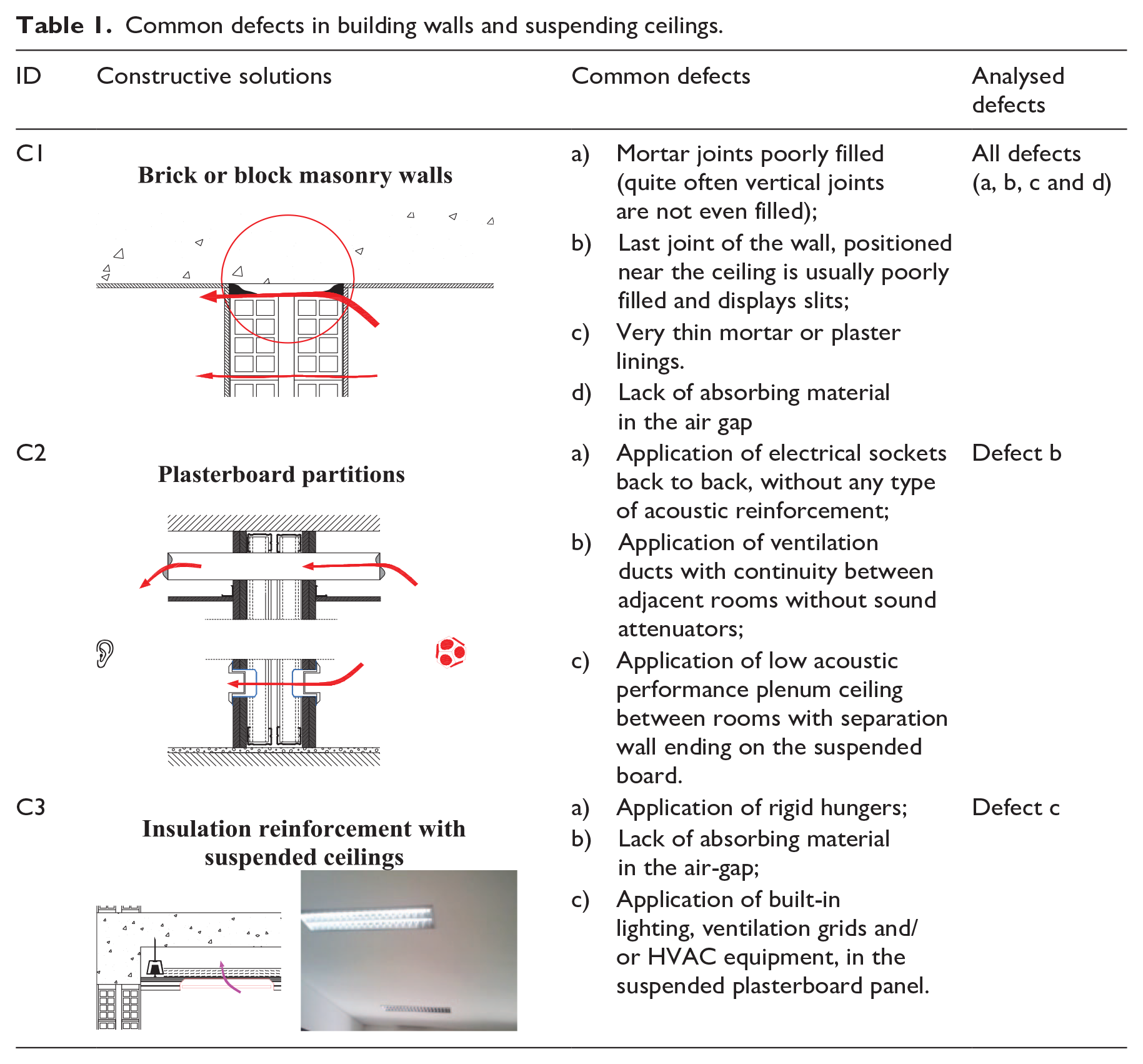
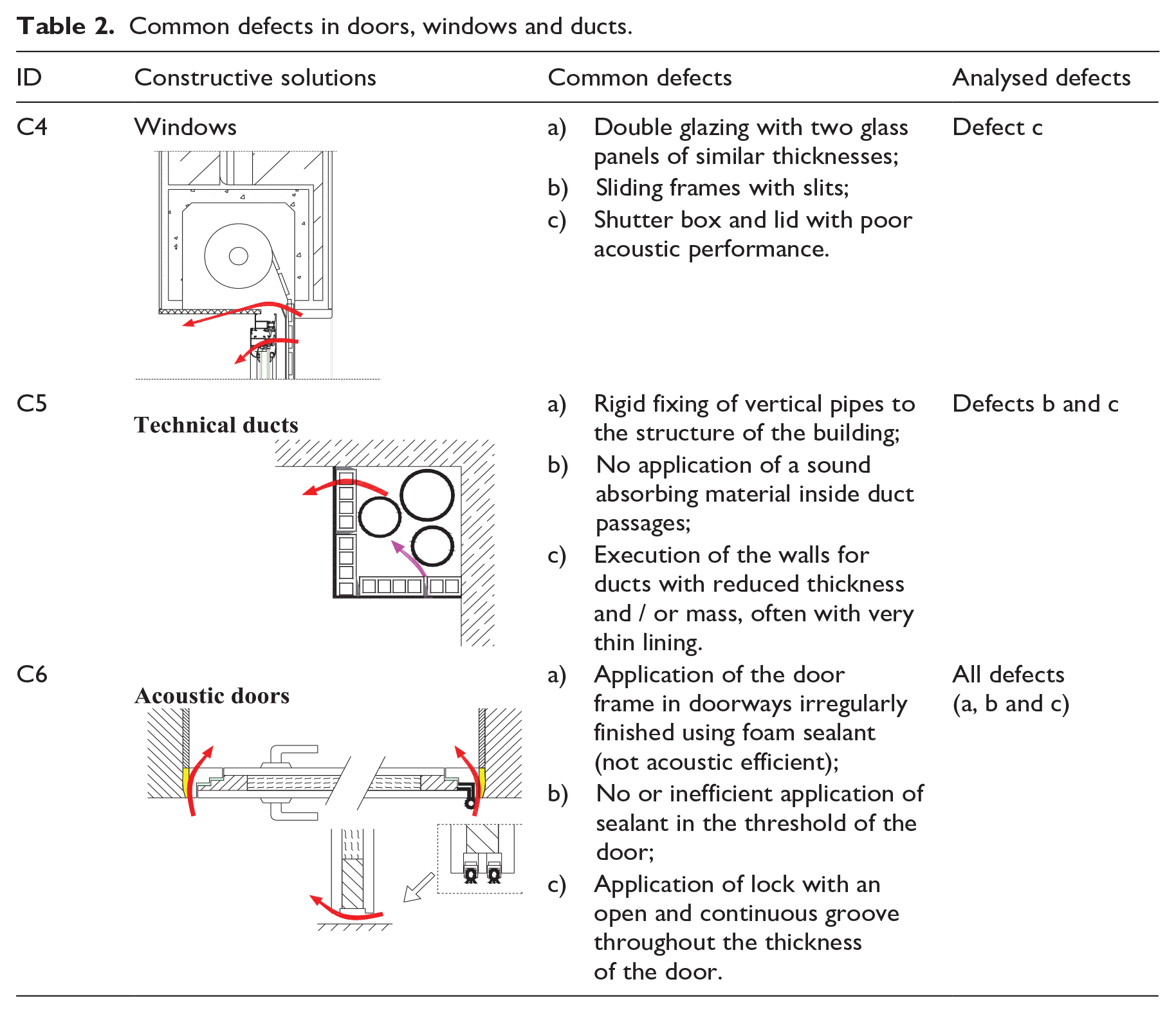
Tables 1 to 3 group some of the usual mistakes occurring in buildings, in Portugal, in the construction of walls, ceilings, windows, doors, shutter boxes technical ducts, floating screeds which are responsible for strong insulation breaks. In these tables, the last column entitled ‘Analysed defects’ identifies the construction errors whose influence in acoustic performance of buildings is discussed in the present paper, while column with called ‘ID’ identifies the building situation and constructive solution to be addressed.
Common defects in building walls and suspending ceilings.
Common defects in doors, windows and ducts.
Common defects in floors.
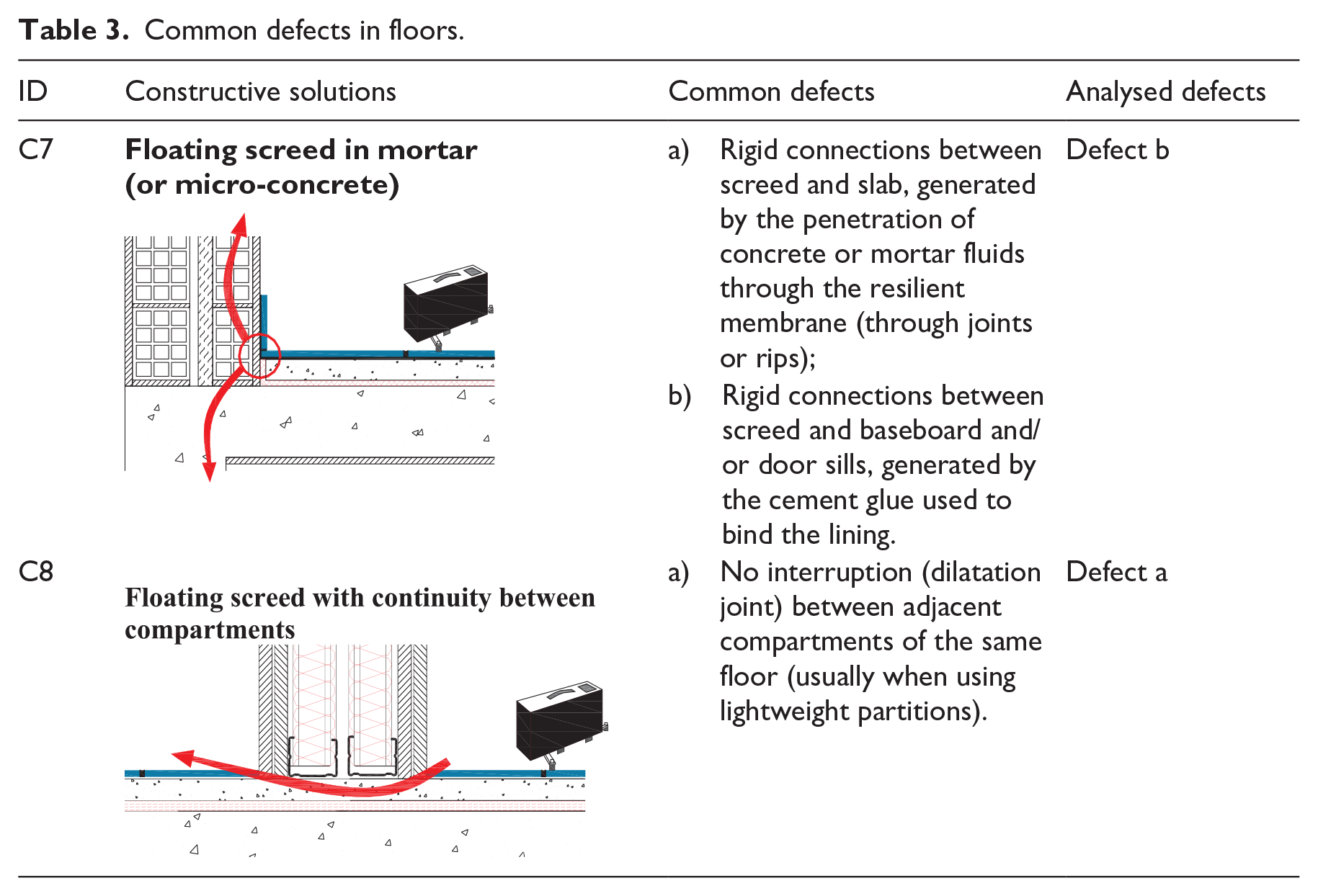
Tables 1 and 2 address defects with influence in airborne sound insulation, while Table 3 presents typical examples of execution errors with a strong influence on the impact sound insulation. This last table also shows a situation that commonly occurs in non-residential buildings, when employing lightweight partitions (see situation identified as C8), leading to the execution of continuous floating screeds between adjacent compartments, which strongly aggravates the impact sound transmission between adjacent spaces of the same floor. Note that the situations identified as C1 to C8 refer to solutions which provide standard sound insulation performances (according to the Portuguese acoustic code 17 ).
In these tables, the column entitled ‘Analysed defects’ identifies the construction errors whose influence in acoustic performance of buildings is here discussed, while column with called ‘ID’ identifies the building situation and constructive solution to be addressed. The situations identified as ID-1 to ID 8 refer to solutions which provide standard sound insulation performances (according to the Portuguese acoustic code 17 ).
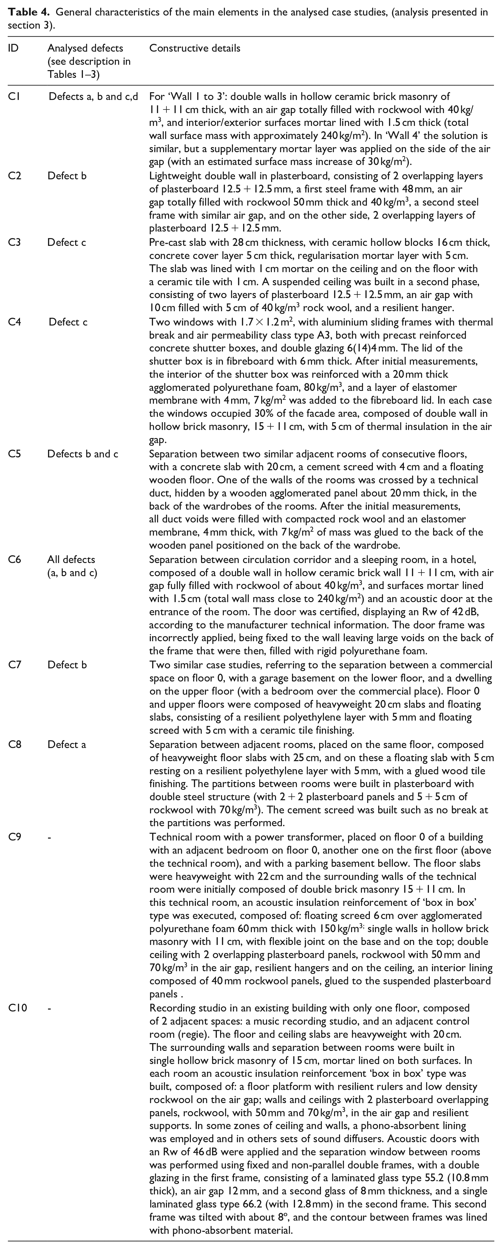
In addition to the case studies indicated in the previous tables, the results of two other situations are also presented in section 3, which, although not corresponding to common defects in current buildings, they refer to situations where small construction errors have great impact on sound insulation, because very high insulation requirements are demanded. These two cases correspond to spaces where a solution ‘box-in-box’ type of insulation reinforcement has been employed. The first case will be labelled as C9 and corresponds to a technical room for installation of an electrical power transformer that is adjacent to a dwelling, and it was found that the top layer of the floating slab composing the box-in-box solution was connected to the walls, in the contour, with cement glue. The second one, labelled C10, corresponds to a music recording studio, with a sound recording room and an adjacent control room layout, where incorrect execution of the window situated on the wall between rooms (where the wooden frame was the same for the double glazing, composed by one vertical glass and one tilted glass) was carried out.
Materials description
Table 4 presents the general characteristics of the relevant constructive details regarding the main elements of the case studies, whose acoustic behaviour will be analysed, in section 3. In all the case studies, reinforced concrete structures were employed, with heavyweight slabs of thickness not less than 15 cm (except for case C3 where lightweight concrete slab was employed), and most of the walls are in hollow brick masonry (with density of 900 kg/m3, not including lining).
General characteristics of the main elements in the analysed case studies, (analysis presented in section 3).
Experimental procedure
The results displayed in the next section correspond to airborne sound insulation between rooms, façade sound insulation and impact sound insulation, obtained from measurements performed according to the procedures defined in ISO standards 16283 – part 1, part 2, part 3.18–20 The main equipment used was (see Figure 1): for measuring sound pressure levels and reverberation times a two-channel analyser (01 dB type SYMPHONIE), microphone 1/2″ (G.R.A.S. type 40AF) and pre-Amplifier (G.R.A.S. type 26AK) and acoustic calibrator (01 dB typeCal 01); for generating sound in airborne sound insulation measurements an omni-directional dodecahedral source (01 dB type DO12), amplifier (InterM type L800) and noise generator (01 dB type RG10); for generating sound in façade sound insulation measurements a hemi dodecahedral column (semi spherical), with built-in amplifier (Morset Sound Development type L-MS-01); noise generator (01 dB type RG10); for generating sound in impact sound insulation measurements a tapping machine Type 3207 (Brüel & Kjær type 3207).
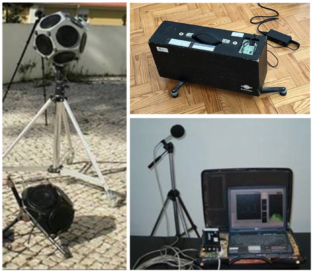
Illustration of the measurement equipment used.
Results
In this section, for each of the main types of usual construction defects, previously identified and grouped (see Tables 1–3), experimental results obtained in different types of buildings are presented for the following cases: when execution errors occurred; for situations apparently without errors and when correction of errors was carried out. In some cases, measurements are also compared with predictions using methods prescribed in ISO standards, in order to provide a reference.
Figure 2 shows the results of in situ tests regarding airborne sound insulation between rooms, for situation identified as ‘ID-C1’ (see Table 1) corresponding to an heavyweight constructive solution, composed of double hollow brick masonry wall, 11 +11 cm, applied under apparently similar conditions (see also drawings on the right of Figure 2), but with different mortar linings’ thicknesses: less than 1 cm (Wall 1 and Wall 2), 2 cm (Wall 3 and 4) and with an additional mortar layer in the interior surface of one of the walls (Wall 4). The presence of absorbing material in the air-gap is also addressed (Wall 2, 3 and 4). The results here provided allow to evidence that for a double ceramic hollow brick masonry wall, it is possible to have DnT,w differences ranging 10 dB. In order to obtain a value of 52 dB, besides the absorbing material in the air-gap, it is necessary to add an extra layer of mortar in the interior face of one of the panels, a procedure that is not common in Portugal. It is important to mention that the Portuguese requirement 17 for airborne sound insulation between rooms of different dwellings is DnT,w ⩾ 50 dB, therefore if this wall is not well built, the acoustic requirement is not met. Furthermore, the presence of absorbing material allowed increasing performance in 2 dB (main differences are located in higher frequencies) and a well performed mortar lining with 2 cm led to an increase in insulation of 6 dB, with main differences situated in medium and higher frequencies. In the lower frequencies (bellow 800 Hz) the wall with absorbing material provided slightly worse results probably due to the influence of workmanship during the construction process.
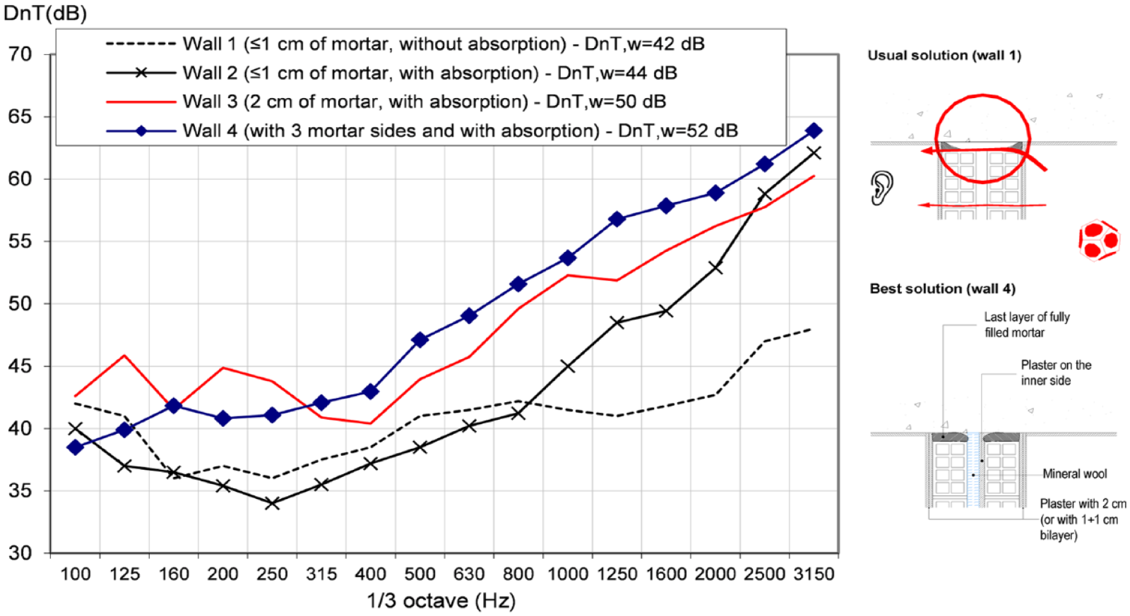
Airborne sound insulation for situation ‘ID-C1’, regarding heavyweight masonry double brick walls, applied in apparently similar conditions but without (Wall 1) or with (Wall 2, 3 and 4) absorbing material in the air -gap and with different linings thicknesses (Wall 2, Wall 3 and 4).
Figure 3 presents airborne sound insulation results of in situ tests obtained for situation ‘ID-C2’, corresponding to two adjacent classrooms in a school, separated by a lightweight plasterboard double wall for the following situations : wall (curve identified as (1)); wall with direct crossing of a ventilation duct (curve identified as (2)) and after the introduction of sound attenuator immediately before crossing the room (curve identified as (3)).
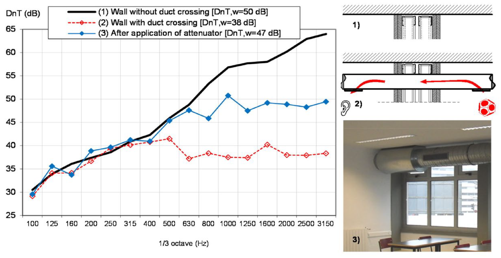
Airborne sound insulation for situation ‘ID-C2’, regarding a double plasterboard wall, separating two adjacent rooms with and without duct crossing.
This figure displays results regarding a defect generated by compatibility decisions among different design professional fields which were not properly addressed. By choosing to directly cross the ventilation duct through the separation wall between rooms, a decrease in the DnT,w value of 12 dB, in relation to the initial situation (without duct crossing), was attained. With subsequent correction, corresponding to the application of a sound attenuator, it was possible to guarantee an insulation decrease of 3 dB in relation to the initial situation, instead of the 12 dB that was occurring. Note that the main differences among curves are located in the higher frequencies.
Figure 4 presents experimental results for situation ‘ID-C3’ corresponding to the separation floor between a commercial space, located on Floor 0 and an adjacent room on Floor 1 of a residential building before and after the application of a suspended sound insulation ceiling. The defect here analysed corresponds to embedded ceiling lamps on the suspended ceiling, forming a sound bridge. This figure also shows the expected result for application of an acoustic suspended ceiling (calculated using ISO 12354-1, based on a calibration of the model by means of initial in situ measurements). The results evidence that the hanging procedure of the lamps on the ceiling, by embedding them, led to a decrease in insulation of 3 dB.
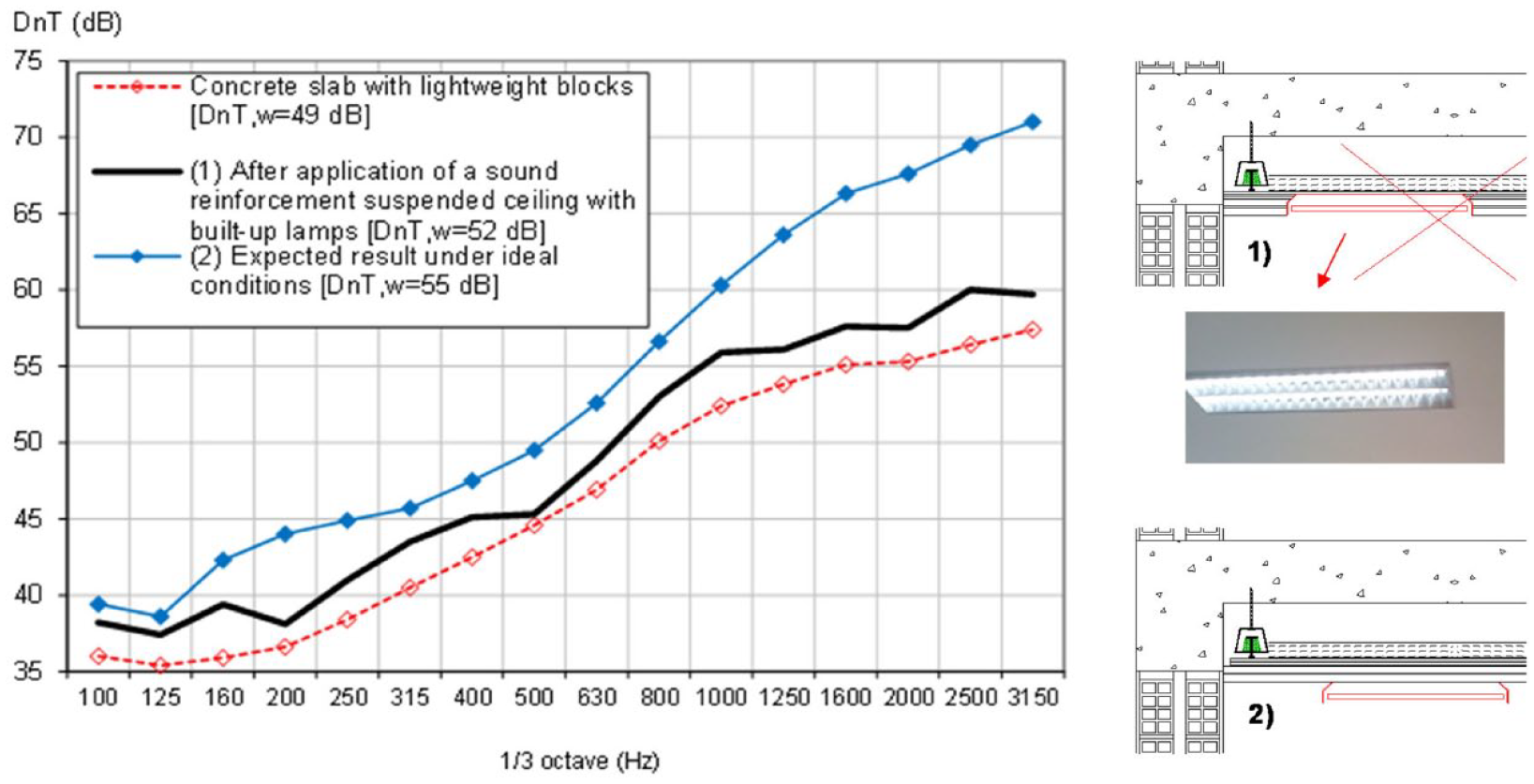
Airborne sound insulation for situation ‘ID-C3’, between a commercial space, situated on Floor 0, and an adjacent room positioned on Floor 1, where a suspended ceiling for sound reinforcement was employed, but with embedded lamps (creating a sound bridge).
Figure 5 shows the façade sound insulation response, according to ‘ID-C4’, obtained in two situations, with similar partitions, where the result is influenced by the low insulation provided by the shutter box. In the case study, sliding windows were applied (which usually provide much lower performance than casement or fixed windows), with an air permeability class A3 (according to standard EN 12207 21 ), and the shutter box is in pre-cast reinforced concrete, without and with thermal or acoustic correction. A difference of 7 dB in performance was obtained by employing an interior absorbing lining in the interior of the shutter box and and by adding a layer of an elastomer membrane to the fibreboard lid. In the case of lightweight shutter boxes, for example, in EPS or XPS, which are usually chosen to meet thermal requirements, it is, usually, not feasible the implementation of an absorbing material inside the shutter box. In these cases (lightweight shutter boxes), at least a total thickness of the inner lining in the zone of the shutter box of not less than 3 cm (e.g. with a first layer of reinforced mortar and a second layer corresponding to a lining equal to that of the remaining wall) and a suitable shutter box cover should be employed.
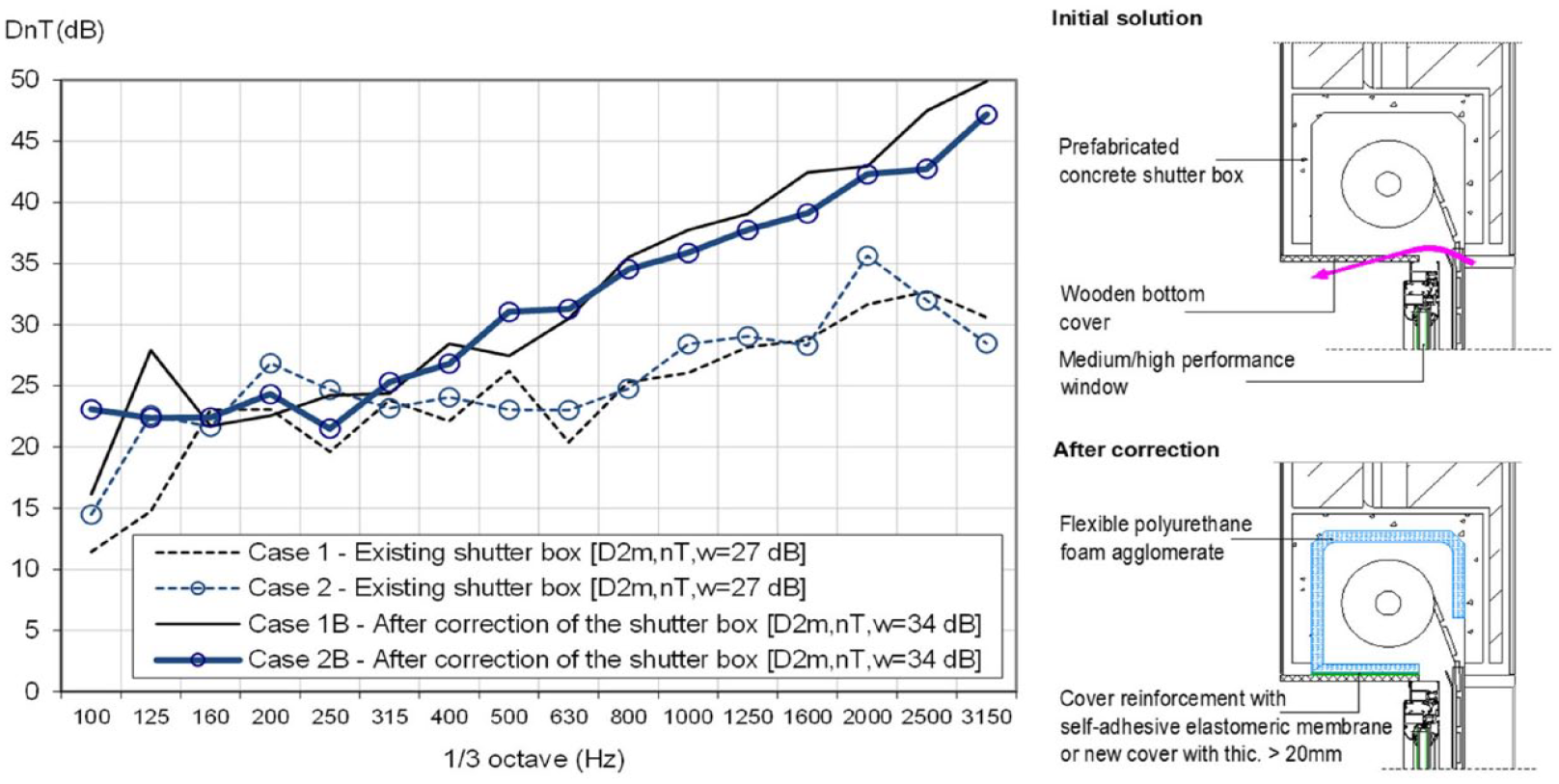
Facade sound insulation regarding situation ‘ID-C4’, in two situations, before and after acoustic correction of the shutter box.
Figure 6 shows the experimental results for airborne sound insulation between two adjacent rooms of different floors, regarding situation ‘ID-C5’, where important indirect transmissions occurred through the ventilation and sewage pipes embedded in walls and hidden behind a wood wardrobe. This figure displays two curves, one corresponding to the described situation (initial situation), where the wood panel is hiding the passage zone, and a second one, measured after performing an intervention in the zone which consisted of filling the existing voids surrounding the tubes with rockwool and applying an elastomer membrane to the wooden panel which forms the back of the wardrobe (see image on the right of the plot). By performing this correction an increase of 4 dB was obtained in the weighted standardised sound level difference. Although it was not possible to perform measurements without tubes’ crossing an even major difference to this situation can be expected.
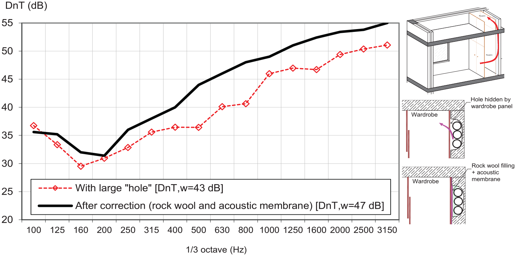
Airborne sound insulation regarding situation ‘ID-C5’, obtained between rooms of different adjacent floors with passage of ventilation and sewage tubes embedded in the walls (initial situation and after intervention).
Figure 7 shows predicted and experimental results between a circulation zone and the interior of a hotel room, regarding situation ‘ID-C6’, with an inadequate application of an acoustic door, whose expected acoustic performance was Rw = 42 dB (the frame was bonded with polyurethane foam and door threshold with sealing device not working). Constructive details on the separation element can be found in Table 4. Note, that the prediction curve in Figure 7 was obtained by applying ISO EN 12354-1, after previous evaluation of the acoustic performance of the main separation element composed of a double wall double brick wall (detailed description provided in Table 4) with door whose assumed performance was that provided by the manufacturer (obtained in the laboratory) and assuming heavyweight flanking elements (double brick walls 11 + 11 cm walls and heavyweight floor and ceiling slabs with 20 cm).
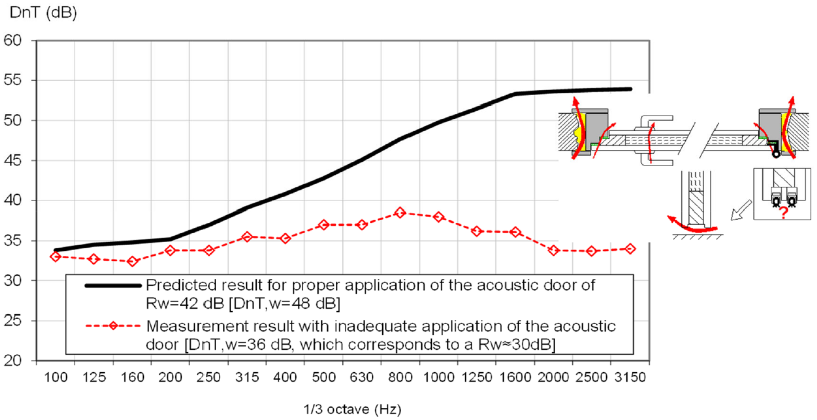
Airborne sound insulation, regarding situation ‘ID-C6’, evaluated between a circulation zone and a room in a hotel building: predicted result under proper application conditions, and experimental corresponding to an incorrect application.
From the analysis of Figure 7 it becomes evident the influence of the procedure used for frame application and door mounting on the acoustic performance of walls with acoustic doors. In this case a decrease in the value of DnT,w 12 dB was obtained, for an incorrect application of the acoustic door.
Figures 8 and 9 show results of measurements, regarding situation ‘ID-C7’ obtained in two distinct buildings, regarding impact sound transmission from the floor below to the floor above, between a commercial space, situated on Floor 0 and an adjacent room, on Floor 1.
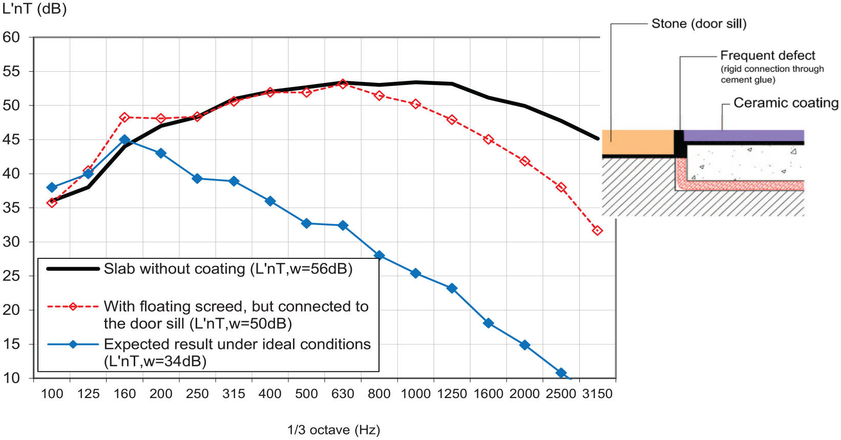
Standardised sound pressure level (L′nT), regarding situation ‘ID-C7’, due to impact sound transmission from the floor below to above, before and after the execution of a floating screed, with a small rigid connection between screed and door sill, and in ideal conditions.
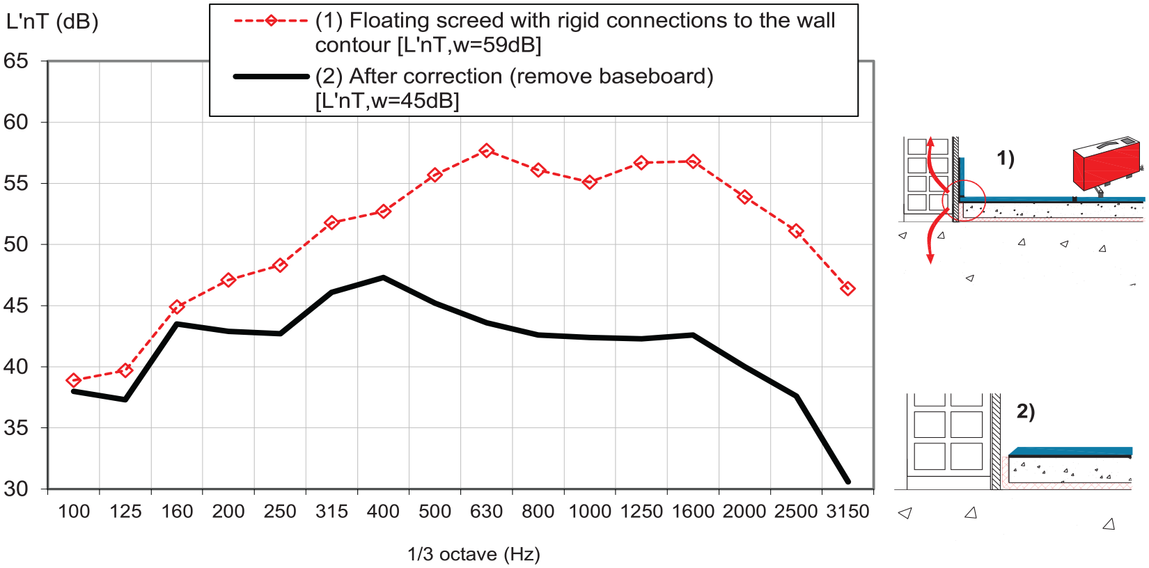
Standardised sound pressure level (L′nT), regarding situation ‘ID-C7’, due impact sound transmission from the floor below to above, after application of a floating screed, with a small rigid connection between screed and the baseboard (curve 1) and after removing the baseboard (curve 2).
In the first building (see Figure 8), the tests were carried out, for a heavyweight reinforced concrete slab, in two phases: first without any additional lining and then with the execution of a floating screed, but with small rigid connections between screed and door sill. Figure 8 also presents the expected result, under ideal mounting conditions (obtained from the curve assuming the slab without coating by subtracting the sound reduction, in 1/3 octave frequency bands, provided by the floating screed which in turn was previously evaluated in laboratory) demonstrating how a very small construction error, can strongly influence the final result, with a difference of 16 dB.
Figure 9 shows results of tests carried out also in two phases, initially, with an apparent rigid connection between the floating screed and the baseboard, generated by the cement glue used for binding the floor covering (common error during construction works). In this case, after noticing the weak acoustic performance, the baseboard was removed and the test was repeated, giving an improvement in the L′nT,w value of 14 dB. This type of problem usually occurs from the premature cutting of the resilient membrane at the contour of the wall (which should only occur after the floor covering is applied) and from the simultaneous application of the cement glue on the lining and on the baseboard (when lining is ceramic or stone). It should be noted that this type of defect, in addition to compromising insulation regarding impact transmission from the floor below to above (usually the relevant noise when commercial spaces are situated under housing zones), also influences the insulation from the floor above to below (which is the usually the most unfavourable situation). In the transmission from above to below, it is expected that this type of error lead to also to a significant reduction in the effectiveness of the floating screed (not illustrated).
Figure 10 shows results regarding situation ‘ID-C8’, obtained for a floating screed solution with continuity between two contiguous lateral rooms, which is often employed when lightweight partitions are applied (usually in plasterboard). In these cases, a floating screed throughout the floor area is often performed, with subsequent execution of the lightweight partitions (solution used in service buildings, hotels, schools and hospitals). This construction procedure, although generally not influencing the impact sound insulation from above to below, strongly aggravates the impact sound transmission between adjacent compartments of the same floor, resulting, for the present case, in a decrease on the L′nT.w value of 31 dB in relation to that obtained for a floating screed without continuity. This performance is worse than that predicted without any floating screed employed (not here displayed). On the other hand, this continuity can also influence the airborne sound insulation between adjacent rooms of the same floor, since flanking transmissions through the floor increase (not displayed).
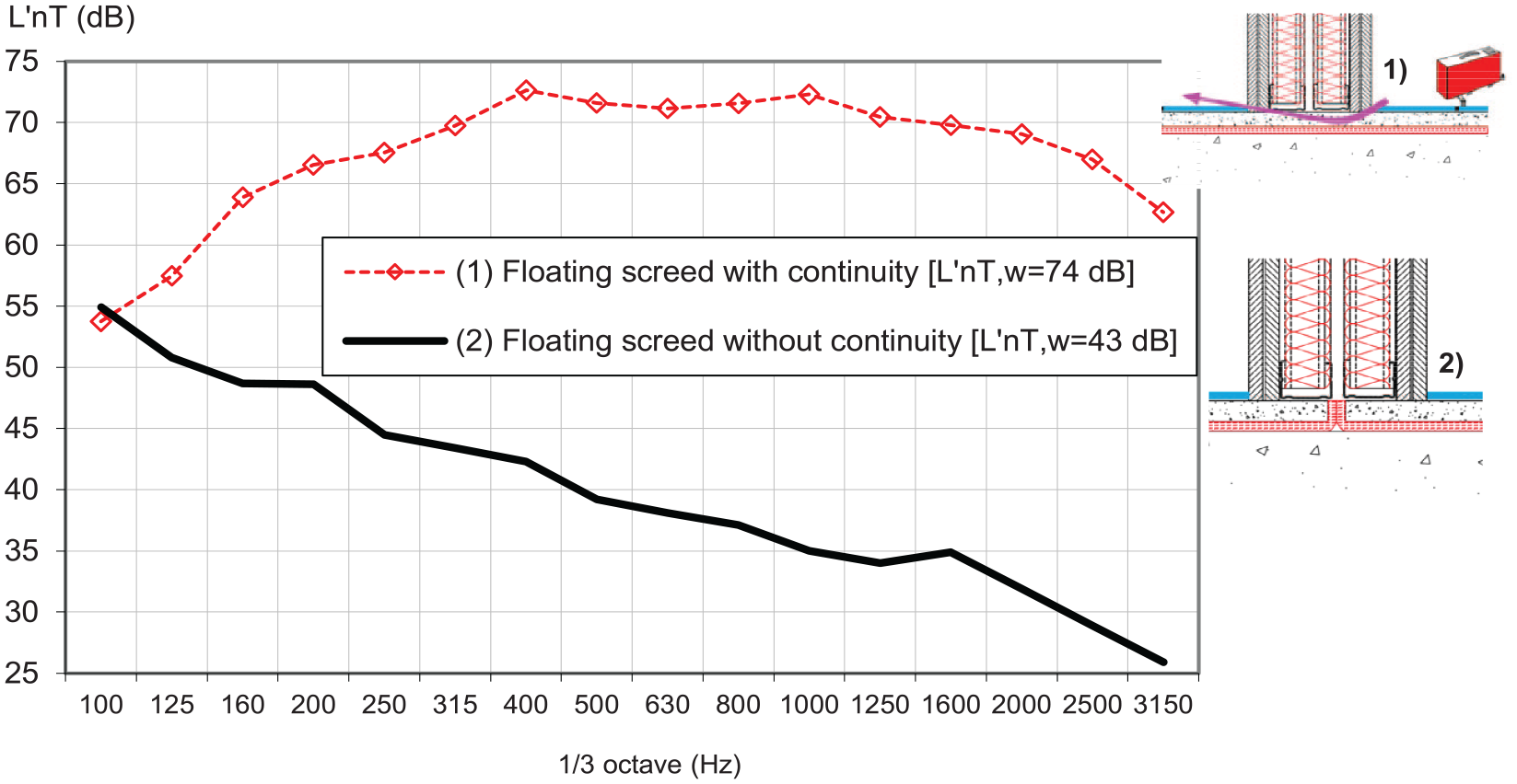
Standardised sound pressure level (L′nT), regarding situation ‘ID-C8’, due to lateral impact sound transmission when applying a floating screed with or without continuity between contiguous lateral rooms.
Figure 11 shows the results regarding situation ‘ID-C9’ of impact lateral sound insulation between a technical room for an electrical power transformer, located on Floor 0 of a multi-family building (which includes garage basement), and an adjacent bedroom on the same floor. This technical room was completely insulated using wall and ceiling acoustic solutions, and on the floor a concrete floating inertia slab, was also implemented (see details on the solutions employed in Table 4). In a first experimental evaluation a value of 56 dB for L′nT,w was obtained, which indicated an almost zero efficiency regarding impact sound reduction provided by the floating slab, for which a final value of L′nT,w lower than 30 dB was expected. During on-site inspection, it was found that the top layer of this slab had been connected to the walls, in the contour, with cement glue. This connection was then cut, until the resilient layer was visible along the contour, and the experimental test was repeated, obtaining a L′nT,w of 44 dB, which, although much better, was still far from the expected value. Later, in a more detailed inspection, it was found that in one of the corners of the floor, where a rigid pipe had been embedded, there was still a rigid connection between the floating slab and the side wall, so the screed was cut in this zone, until reaching the resilient material that was under it. With both corrections it was possible to totally ‘disconnect’ the floating slab of the contour and support slab, as confirmed by the final acoustic tests, who displayed a value of L′nT,w of 26 dB.
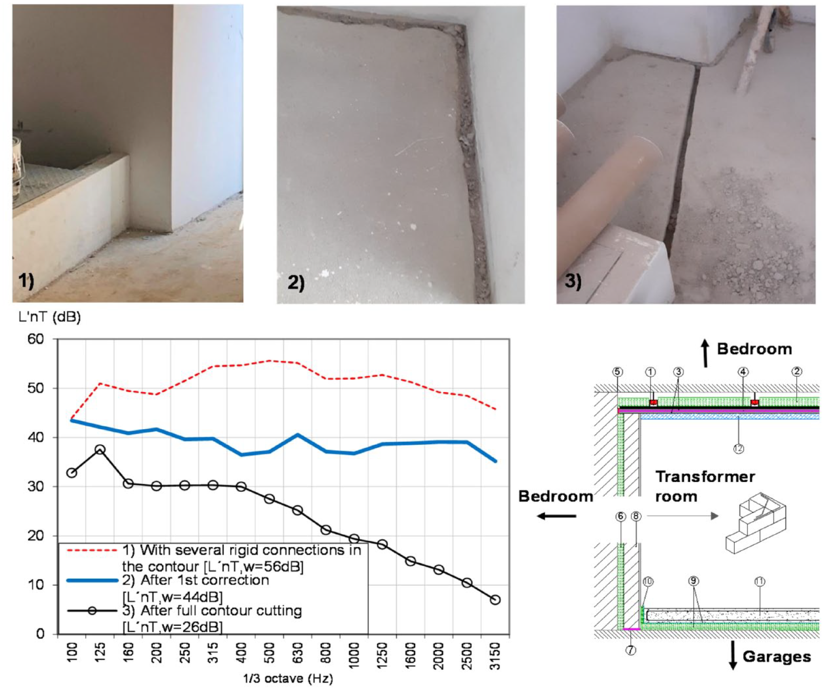
Standardised sound pressure level (L′nT), regarding situation ‘ID-C9’, due to lateral impact sound transmission between spaces of the same floor: (1) with connections in the wall contour; (2) when disconnecting the contour; (3) when disconnecting the contour and a connection in a pipe passage zone (according to pictures above).
Figure 12 shows sound insulation results regarding situation ‘ID-C10’ between the control and the studio room in a recording studio, obtained in three different phases: in phase 1 after the incorrect execution of the window situated on the wall between rooms (where the wooden frame was the same for the double glazing, composed by one vertical glass and one tilted glass, according to constructive details given in Table 4); in phase 2, after the correction of the window frame (inserting two separate frames with application of absorbing material in the contour, between frames); and in phase 3, after correction of cable crossing zones (there were cable jackets opened). Since the frame, in phase 1, allowed a rigid connection between both sides of the separation, this defect, in addition to significantly reducing airborne sound insulation, also led to a strong impact sound transmission. Differences in airborne sound insulation of 14 dB were found and for 12 dB for impact sound insulation related with the frame defect.
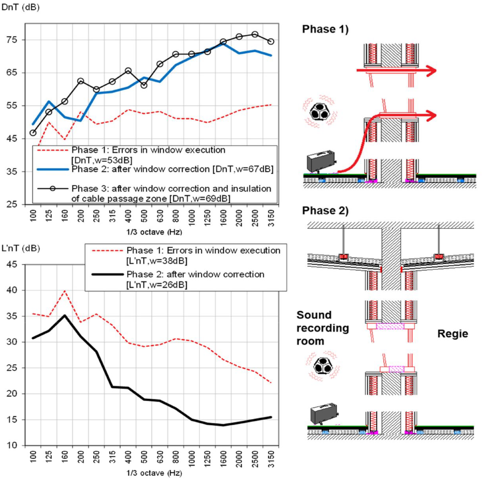
Standardised airborne sound insulation, (upper figure) and impact sound insulation (lower figure), regarding situation ‘ID-C10’, between recording room and regie, in three different phases of the construction.
Discussion
The performed analysis allowed to verify for double hollow brick masonry walls, differences among apparently similar solutions within a range of 6 dB, mainly due to their great heterogeneity, particularly at joints between bricks and mortar lining. This result was higher than that obtained by Labres et al. 15 who verified 1 and 2 dB differences with gaps above the wall and with no vertical mortar filling, respectively, for a single brick wall, displaying a reference acoustic performance of 43 dB. In fact, if higher performances are expected, similar defects provide higher differences. For another defect resulting of lack of interconnection between acoustics and other professional fields involved, consisting of direct crossing a ventilation duct without sound attenuation, on a wall between adjacent rooms, an insulation reduction of 12 dB was obtained. When using acoustic suspended ceilings, the application of embedded lighting originated a decrease in insulation of 3 dB. In the case facades, the use of pre-cast concrete shutter boxes without acoustic treatment led to a decrease in insulation of 7 dB. When ducts are embedded in walls connecting adjacent rooms of different floors, a break of 4 dB was found. If acoustic doors are not corrected mounted a decrease in insulation of 12 dB was found. For high acoustic performance solutions, such as the case of a glazing solution in a recording studio, a defect on the frame and contour of the span led to a decrease in insulation of 16 dB.
Regarding impact sound insulation, for defects related with the existence in floating screeds of rigid connections to the contour, the losses are even greater, varying, for the analysed situations, between 12 and 31 dB, being the deviation greater for higher expected performances. From the analysis of the previous figures (see Figures 8–12) there are small errors of execution, many of them difficult to find, which can provide very low impact sound insulation performance. Some of the defects can even neglect the sound improvement provided by the solution employed. For example, a small rigid connection of the floating screed to the contour can cause a loss of effectiveness greater than 20 dB (in the example of Figure 11 it reached 30 dB).
The methodology here employed made use of in situ measurements where, for most situations, a comparison before and after the correction of execution defects was provided, which allowed to quantify the decrease in effectiveness provided by several defects. For some of them it would be impossible to quantify the impact on sound insulation by using laboratory procedures. When using laboratory conditions, a rigorous comparison between apparently similar situations may be found, however this approach is not always feasible.
Conclusions
This work addressed the influence of small construction defects and/or wrong decisions made by other professional fields involved in the design stage, in the final sound insulation performance of buildings. In order to quantify this influence, several buildings with heavyweight concrete structure, describing the Portuguese building traditional construction were chosen and in situ tests were carried out to evaluate airborne, façade and impact sound insulation. For most situations, results were obtained before and after the correction of the main defects, allowing to quantify for specific situations, their contribution to the final acoustic performance.
Despite the limited scope of the results, it was possible to evidence that final acoustic performance in buildings often depends more on small details of execution than on the general characteristics of the constructive solutions employed.
The implementation of non-traditional constructive solutions, with expected high acoustic performance, such as the use of floating slabs in a ‘box in box’ insulation system, in which construction stakeholders are unaware of their correct application, may end up providing a worse behaviour than other traditional solutions with predicted lower performance. In addition to the construction process control, a good acoustic final performance of a building also requires proper coordination during design stage, being essential an interconnection between acoustics and other professional fields involved, namely architecture, stability and technical installations.
Footnotes
Declaration of conflicting interests
The author(s) declared no potential conflicts of interest with respect to the research, authorship, and/or publication of this article.
Funding
The author(s) disclosed receipt of the following financial support for the research, authorship, and/or publication of this article: This work was financed by FCT / MCTES through national funds (PIDDAC) under the R&D Unit Institute for Sustainability and Innovation in Structural Engineering (ISISE), under reference UIDB / 04029/2020.