
Abstract
This paper presents a wave and finite element method for predicting the sound transmission loss of double-leaf walls comprising panels of arbitrary complexity separated by a cavity which can contain air or an insulating material. The method is verified against analytical models and validated against a number of different experimental measurements. The method is then used to investigate the effect of various parameters on the sound transmission performance of a double-leaf cross-laminated timber (CLT) wall construction. Parameters investigated include the flow resistivity of the insulating layer separating the wall panels and the effect of panel thickness and orientation. The effect of a neoprene rubber layer in between the CLT panels is also investigated.
Introduction
Cross-laminated timber (CLT) is a laminated wood product consisting of layers of wooden beams laid perpendicular to the beams in adjacent layers and bonded with adhesive. Layering the timber in this way gives the panels a relatively high stiffness along two axes. CLT is becoming a popular choice as a building material as it has a comparatively low density, can be prefabricated off-site, and is a sustainable alternative to traditional materials. However, predicting sound transmission through CLT constructions using conventional analytic and numeric methods is difficult due to its complex structure.
It is common practice to model the vibroacoustic behaviour of a CLT panel as being equivalent to that of an orthotropic plate. Krajči et al. measured the sound reduction index of a three-layer CLT panel 1 and compared these measurements to calculations performed using two different models: one where the panel was modelled as a finite isotropic plate and another where the panel was modelled as an infinite orthotropic plate. They noted that below coincidence, occurring around the 250 and 315 Hz one-third octave bands, the measured sound reduction index agreed well with the levels predicted using the isotropic model, but above coincidence the agreement was not as good for either model. Santoni et al. 2 presented a model to predict the modal-average radiation efficiency of a CLT panel in which the panel was modelled as a thin, homogeneous, orthotropic plate with frequency-dependent mechanical properties. Santoni et al. 3 also presented a method for determining the radiation efficiency of a point-excited CLT panel, and validated this approach against experimental measurements. This method also modelled the panel as a thin orthotropic plate with stiffness characteristics which were determined experimentally. Santoni et al. 4 presented another model for predicting the sound transmission loss and radiation efficiency of a CLT panel which also assumed that the panel could be modelled as an orthotropic thin plate with frequency dependent material properties.
Approaches that assume the CLT panel is equivalent to an orthotropic plate work well at lower frequencies where the CLT panel does indeed behave like an orthotropic plate. However, at higher frequencies, the vibroacoustic behaviour of the panel becomes more complicated, with many different wavemodes cutting on, and a more sophisticated model which captures this behaviour may be preferable.
An alternative is to use the wave and finite element (WFE) method, which can be used to investigate wave propagation in panels which are periodic or homogeneous in the plane of the panel. 5 In this method, a small segment of the structure is modelled using a conventional finite element (FE) software package. The mass and stiffness matrices from this FE model are then post-processed to determine characteristics of the waves which may propagate within the entire structure. The method can also be applied to calculate the sound transmission loss through a panel by modelling the acoustic loading on the outer surfaces of the panel using an analytic formulation. 6 A significant advantage of using the WFE method is that it can be applied to straightforwardly calculate the sound transmission loss of panels with arbitrary complexity through the thickness. The WFE method has previously been used to investigate the vibroacoustic characteristics of single-leaf CLT panels,7,8 with the results comparing favourably to experimental measurements. The WFE method has also been extended to analyse the sound transmission of multi-layered panels with intermediate fluid layers by Yang et al. 9 This method models the acoustic propagation within each fluid layer analytically. Such a model is well suited for predicting the sound transmission loss of double-leaf walls and the application of a similar approach to this problem will be explored in this paper.
As mentioned above, this paper concerns the prediction of the sound transmission loss of double-leaf CLT wall systems. Double-leaf wall systems consist of two panels separated by an air cavity or an insulating layer and are known to produce generally higher sound transmission loss compared to single-leaf wall systems. This improved sound transmission loss can be attributed to the air cavity or insulating layer between the leaves introducing additional large impedance changes in the transmission path of sound through the wall. However, the air cavity/insulating layer also dynamically couples the two panels which means that the vibroacoustic characteristics of a double-leaf wall are quite different to those of a single-leaf wall. In particular, the coupling provided by the cavity between the two leaves results in a phenomenon commonly referred to as the mass-air-mass resonance, 10 which causes significant sound transmission at the resonance frequency. Acoustic resonances in the cavity between the wall leaves also affect the sound transmission performance of the wall. For double-leaf wall systems with thin, stiff leaves, above the mass-air-mass resonance frequency the sound transmission loss typically increases with frequency much more quickly than for a single-leaf wall, since the second leaf acts like a mass driven through a spring (the air or insulating material in the cavity) by the motion of the first leaf. 10 Theoretical analysis of the sound transmission behaviour of double-leaf walls is less well-developed than that for single-leaf walls, due to the increased number of parameters on which the problem depends (e.g. panel structure and materials, the size of the gap between the panels, and whether the gap contains insulating material) and more complex construction (e.g. studs joining the panels also provide a path for sound transmission through the wall). The understanding of the acoustic performance of these walls is therefore heavily reliant on empirical data.
London 11 studied the effect of cavity thickness in double-leaf walls both theoretically and experimentally. He considered walls made from thin sheets of aluminium, plywood and plasterboard of various thicknesses with a gap between the two leaves which contained either air or an insulating material. London found that for walls with an air-filled cavity, even cavities with a very small thickness produced a significant increase in transmission loss in comparison to a single-leaf wall constructed from identical panels. London also investigated the effect of introducing fibreglass into the cavity and found that this produced significant increases in transmission loss only when the mass-per-unit-area of the wall leaves is relatively small. He concluded that the effect depends on the ratio of the impedance of the insulating material to the impedance of the walls, and therefore for a heavy wall the insulating material adds little to the already large impedance change. Loney 12 investigated the effect of placing insulating material in the cavity of double-leaf walls constructed from gypsum board with steel studs. He reported the results of experiments using insulating materials of different densities, thicknesses and types (mineral wool and glass fibre). The transmission loss was found to be generally higher when the cavity contained a thicker layer of insulating material, although most of the effect could be attained by using an insulating layer which was a fraction of the cavity thickness. Similarly, Hongisto et al. 13 found that for mechanically uncoupled double-leaf walls, introducing an insulating layer with thickness which was one-quarter to one-third of the cavity thickness was almost as effective as filling the entire cavity. Hongisto et al. 13 also tested several mechanically uncoupled double-leaf walls filled with mineral wool insulation with different flow resistivities of between 8 and 300 kPa.s.m−2 (which apparently covers the range of flow resistivities of commercial mineral wools which were available to them). They found that changing the flow resistivity of the insulation material had a relatively minor effect, with the one-third octave band sound transmission loss being within 6 dB for all cases (between 63 Hz and 6.3 kHz).
As discussed above, an insulating material such as glass wool is often inserted into the cavity of double-leaf walls to provide sound insulation. According to Fahy and Gardonio, 10 the insulating material suppresses the acoustic resonance phenomenon which occurs in such constructions. This is true for normal incidence transmission as well as for oblique-incidence or diffuse-field sound transmission, for which the increased effective path-length of the sound through the absorbing material between reflections can further increase the attenuation the insulation layer provides. 10
This paper is laid out as follows. In the next section, a brief description is given of the approach taken to model sound propagation through the insulating material within the cavity. This is followed by the presentation of an analytical model for calculating sound transmission through a double-leaf wall-system with thin leaves made from a stiff isotropic material. Finally, a model for predicting the sound transmission loss through a double-leaf wall is presented in which the structural response of the individual leaves is modelled using the WFE method. This allows the analysis of wall systems with panels which are homogeneous in-plane, but which are of arbitrary complexity through the thickness. The WFE model is validated against the analytical model and a range of experimental results. The method is then applied to predict sound transmission through double-leaf CLT wall systems. Predictions made using the method are compared with a limited number of experimental results and the method is then used to explore the effect of different design parameters on the sound transmission loss of such walls.
Modelling sound transmission through double-leaf wall systems
Acoustic model for the cavity insulation material
A number of different approaches can be taken to model sound propagation through an insulating material. Here we use an equivalent fluid model14,15 which assumes that, at a particular frequency, the insulating layer can be modelled as an equivalent fluid with a characteristic specific acoustic impedance

and

where
Analytical model
The situation considered is shown in Figure 1. A time-harmonic plane wave, with circular frequency

where
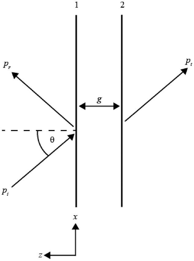
Schematic showing a plane wave incident on a double-leaf wall system. The directions of the incident, reflected and transmitted waves exterior to the wall are indicated by the arrows. The coordinate system is also shown.
The outer left surface of the wall lies in the
The pressure of the wave reflected from the left outer surface of the wall is given by

whilst the pressure of the wave radiated from the right outer surface of the wall is given by

where
The displacements of the surfaces of the kth panel (k = 1 or 2) in the z-direction are given by

where

Similarly, for the right surface of the right panel,

The acoustic pressure within the fluid in the cavity,

and should vary as

Substituting equation (10) into equation (9) gives

The general solution to this equation is of the form

where


where

and

In this analytical model, the panels are modelled as thin homogeneous and isotropic plates. According to Kirchhoff-Love plate theory, the displacement amplitude of the kth panel must satisfy

where

and

Equations (8), (13)–(16) can be combined to give the amplitude of the transmitted pressure

where


and

The simple analytical model described above is similar to that presented in section 5.9 of Fahy and Gardonio 10 but uses a different model for the structural response of each panel and also includes the effect of an insulating layer.
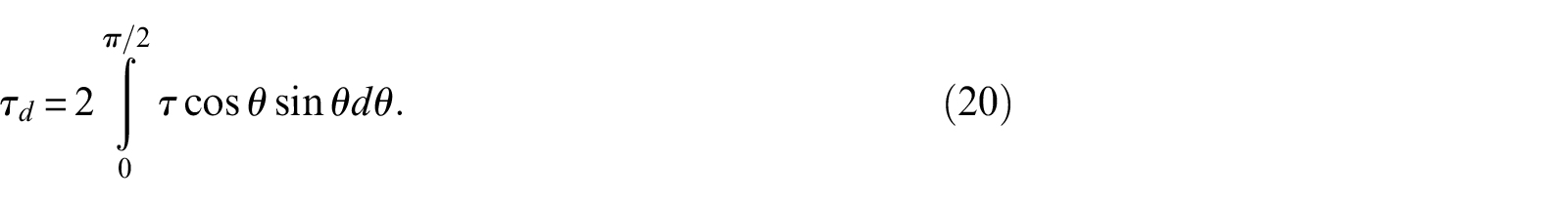
The power transmission loss coefficient can be calculated as
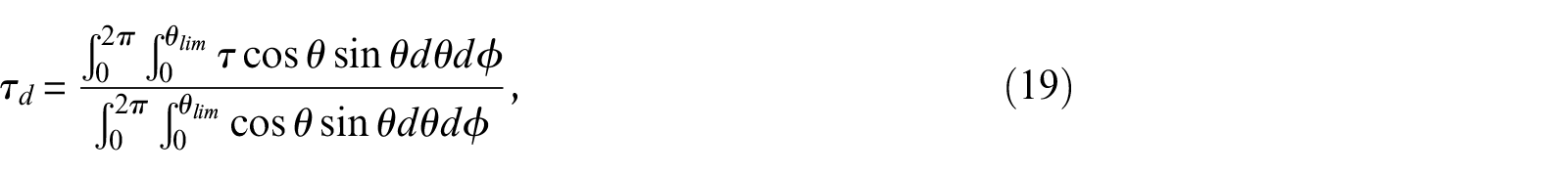
where
Generally, calculations of the sound transmission loss of building partitions made using equations (19) and (20) with
Villot et al.’s method defines a finite panel transmission coefficient,

where
The diffuse-field power transmission coefficient for the finite panel is then calculated using equation (19), but with
Figure 2 plots the normal-incidence sound transmission loss produced by a double-leaf wall system with and without insulation in the cavity. This figure was generated using the analytical method described in this section and is similar to Figure 5.15 in Fahy and Gardonio. 10 The wall is intended to be representative of a typical internal building wall with 12.7 mm thick gypsum board leaves separated by 0.2 m. The first dip in the transmission loss curves (the dips at the lowest frequency for both curves) is caused by the mass-air-mass resonance. The series of dips at higher frequencies for the wall without insulation correspond to frequencies where the wavelength of the sound is equal to an integer multiple of the cavity width (i.e. these are caused by cavity resonances). The insulating material does not have much of an effect below the frequency of the first cavity resonance, although the frequency of the mass-air-mass resonance shifts slightly and the value of the transmission loss at this frequency also changes slightly. However, the insulating material clearly dampens the cavity resonances occurring at higher frequencies, increasing the transmission loss.
Normal incidence transmission loss of a double-leaf wall: wall with an air cavity (solid curve), wall with insulation in the cavity (dashed curve). This wall comprises two panels with mass density of 3 kg.m−2 made from isotropic material with Young’s modulus 5.52 MPa and Poisson’s ratio 0.2 separated by a gap of 0.2 m. The insulating material has flow resistivity of 2 kPa.s.m−2.
WFE method
In the analytic model presented in the previous section, the individual leaves/panels of the double-leaf wall were assumed to be accurately represented by thin Kirchhoff-Love plates. This is clearly not an appropriate assumption for many wall structures – including the CLT panels considered in this paper. Therefore, a more sophisticated approach is required instead. In this paper, the response of each panel is modelled using the WFE method. This requires that a small segment of each panel is modelled using FE. This segment is typically a rectangular prism with the FE model being one element wide in the plane of the panel and comprising a sufficient number of elements through the thickness in order to accurately represent the panel. Figure 3 shows a schematic of the top surface of the FE model. The segment is of size

where
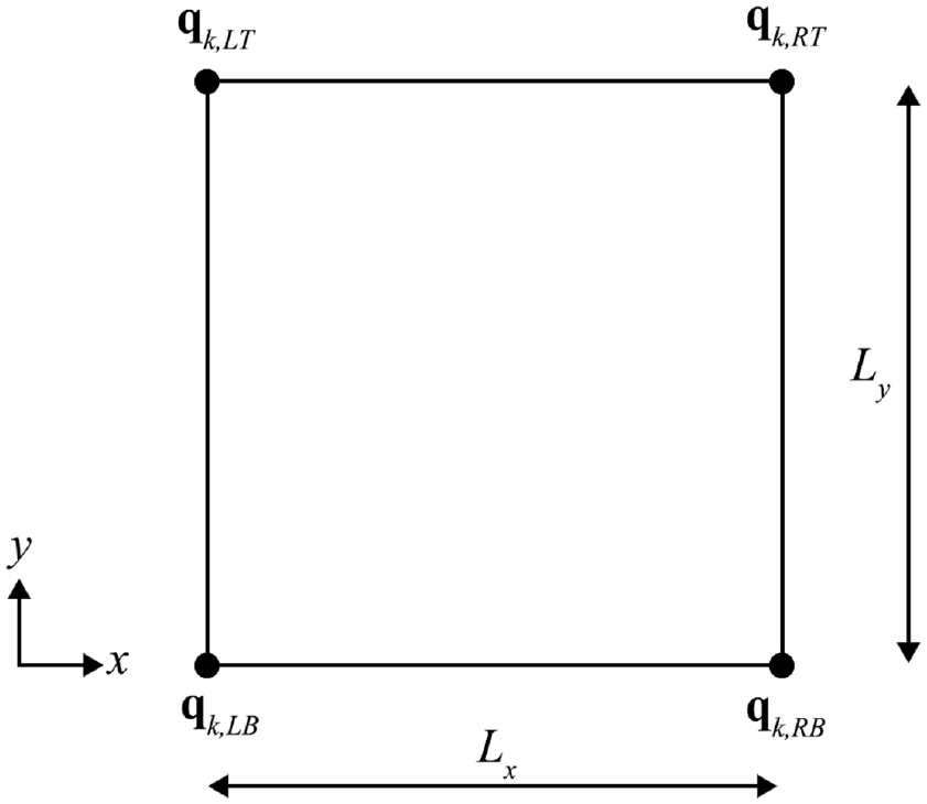
Schematic showing the FE model of the segment for the
The vector of DOFs of the segment is partitioned as

where

and

The general problem is identical to that considered in the previous section, with the left panel of the double-leaf wall excited by an incident time-harmonic plane wave with complex pressure given by equation (3). Because the panels, equivalent fluid within the cavity, and the surrounding air are all homogeneous in the

where
where
Equilibrium at hypernode 1 requires that

where

Premultiplying equation (23) by

where
The pressure stress acting on the left (exterior) surface of the left-hand panel shown in Figure 1 (which is located at

Similarly, the pressure stress acting on the left (interior) surface of the right-hand panel shown in Figure 1 is given by equations (10) and (12) with

Coupling vectors

The linearised momentum equation can be used to deduce the following expressions for the z-displacement amplitudes at the node in the


The vectors of external nodal forces acting on the node at the

where

where
Substituting equations (32) and (33) into equation (36), utilising equations (35a-d) and rearranging, yields the following expressions for the vectors of equivalent external nodal forces:


where
and

where

Substituting equations (38a–b) into equation (31) yields

and

where

Equations (41a–b) can be combined to yield a single matrix equation which can be solved for
Note that the modelling approach described in this section is similar to that presented in Yang et al. 9 (the exact formulation is slightly different and specific to a double-leaf wall containing an insulation layer.)
Validation and verification
In this section, the analytical and WFE models presented in this paper are verified by comparing predictions made using those models and another analytical model. The methods are then validated by comparing the sound transmission loss values calculated using them with experimental measurements.
The analytical model used for these comparisons is taken from §5.9 of Fahy and Gardonio 10 and models the sound transmission of an obliquely incident plane wave through an infinitely large double-leaf wall with leaves which are thin flexible plates separated by an air cavity. Fahy and Gardonio (equation 5.105) give the expression for the ratio of the transmitted to incident pressure amplitudes as
where

and
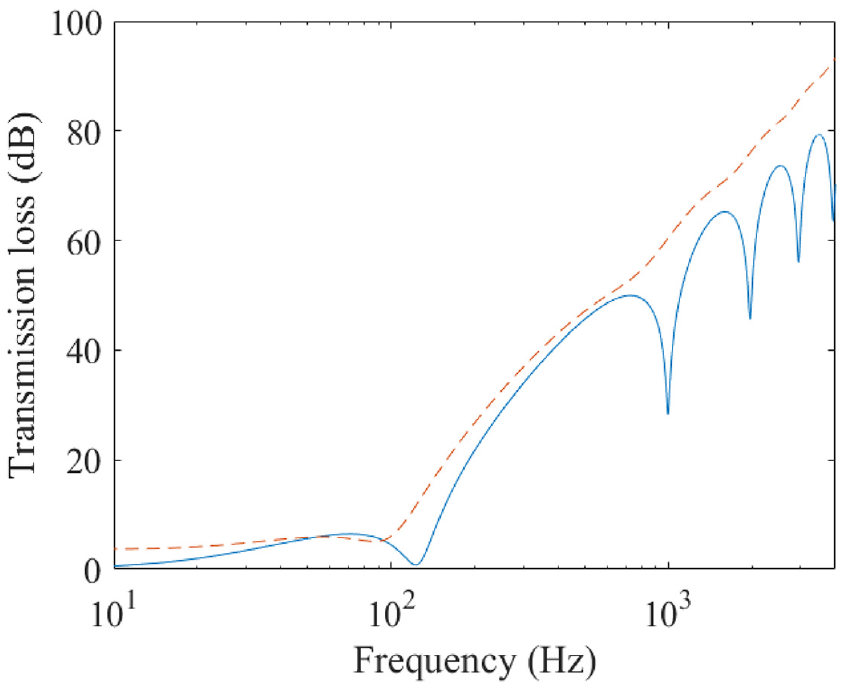
Figure 4 plots the sound transmission loss through a double-leaf steel wall for a single incidence angle and compares results generated using the WFE method described in this paper with results generated using equations (43) and (44). The analytic model described in this paper produces identical results to the WFE method described in this paper. The steel was assumed to have a density of 7800 kg.m−3, a Young’s modulus of 200 GPa, a Poisson’s ratio of 0.28 and a damping loss factor of 0.01. The steel was modelled using a single ANSYS SOLID45 element, with dimensions of
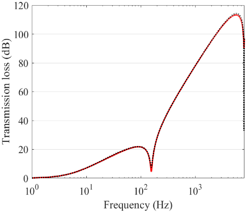
Sound transmission loss spectrum for a plane wave incident on a double-leaf wall with two 2 mm thick steel panels.
In order to validate the WFE method, predictions were made for a number of cases considered in the experimental study of Hongisto et al. 13 which presents sound transmission loss measurements for a double-leaf wall constructed from two 2 mm thick steel plates with either an air cavity or a cavity filled with glass wool. The wall had lateral dimensions of 1105 mm × 2250 mm.
For the predictions made using the WFE method, the steel was assumed to have a density of 7800 kg.m−3, a Young’s modulus of 200 GPa, a Poisson’s ratio of 0.28 and a damping loss factor of 0.01. The diffuse-field sound transmission loss was calculated using Villot’s windowing method with the windowing size set equal to the lateral dimensions of the wall. The steel plates were each modelled using a single ANSYS SOLID45 element. Structural damping was incorporated into the WFE model by multiplying the stiffness matrix of the FE models by a factor of
Figure 5 compares results calculated using the WFE method with experimental results from Hongisto et al. 13 for double-leaf walls with leaves made from 2 mm thick steel panels with air cavities of width 25, 42, 84, and 125 mm. There is good agreement between the predictions and the measurements at most frequencies and the dip in the transmission loss spectrum due to the mass-air-mass resonance at low frequencies is predicted accurately.
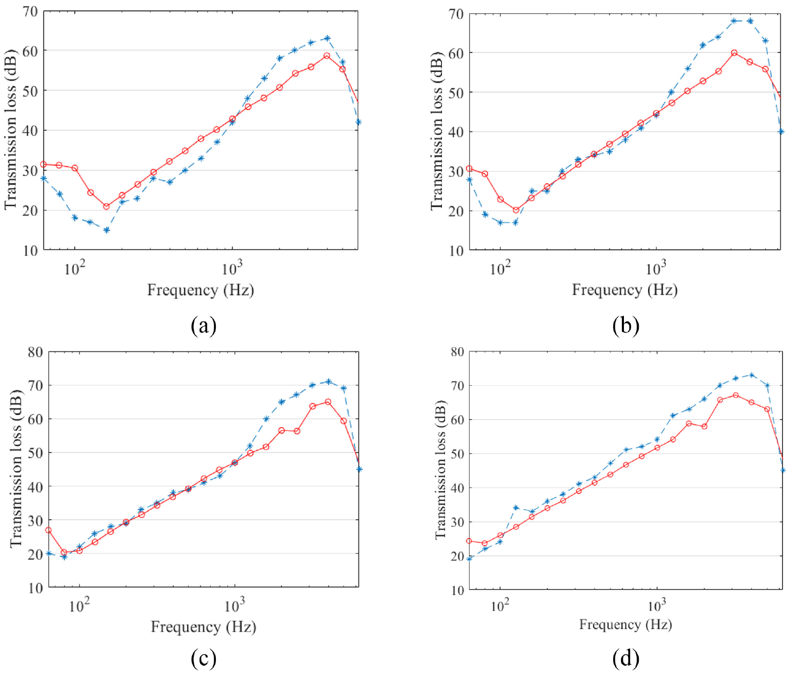
Diffuse field sound transmission loss of a double-leaf wall with 2 mm thick steel leaves separated by an air cavity of width
According to Fahy and Gardonio,
10
for normal incidence transmission, the mass-air-mass resonance frequency
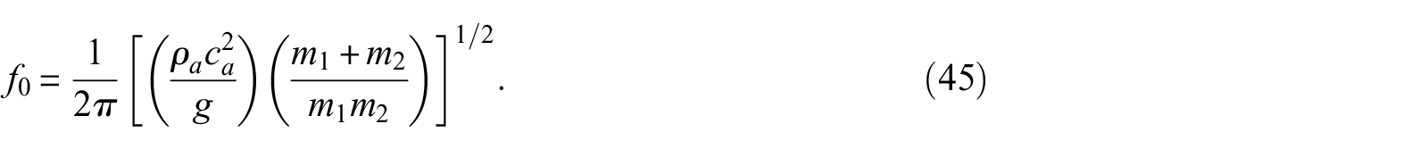
This frequency increases by a factor
Sound transmission loss of double-leaf CLT wall systems
Validation against previously published results
Hoeller et al. 22 report experimental measurements of the sound transmission loss of a double-leaf CLT wall. The wall consisted of two 78 mm thick, 3-layer CLT panels separated by a 25 mm cavity which was filled with glass fibre insulation. Note that the characteristics of the glass fibre insulation used in these experiments was not recorded in Hoeller et al. 22 These experiments were undertaken in the acoustics laboratory of The National Research Council of Canada (NRC).
The WFE method described in this paper was used to predict the diffuse-field sound transmission loss of this wall. The modelling approach is similar to that used for model 1 in Yang et al.
7
in that each CLT panel was modelled as a laminate with each layer being of equal thickness and being an orthotropic solid material. The FE segment used in the WFE model had dimensions of 10 mm × 10 mm and consisted of a stack of 6 cubic SOLID185 ANSYS elements. The properties of the orthotropic solid used to model each layer are given in Table 1 and are identical to the estimates used in Yang et al.
7
which were taken from Hoeller et al.
22
Note that the coordinate system utilised for the material properties listed in this table differs from that used previously. Here, the
Properties of the orthotropic solid used to model each layer of the CLT panels.
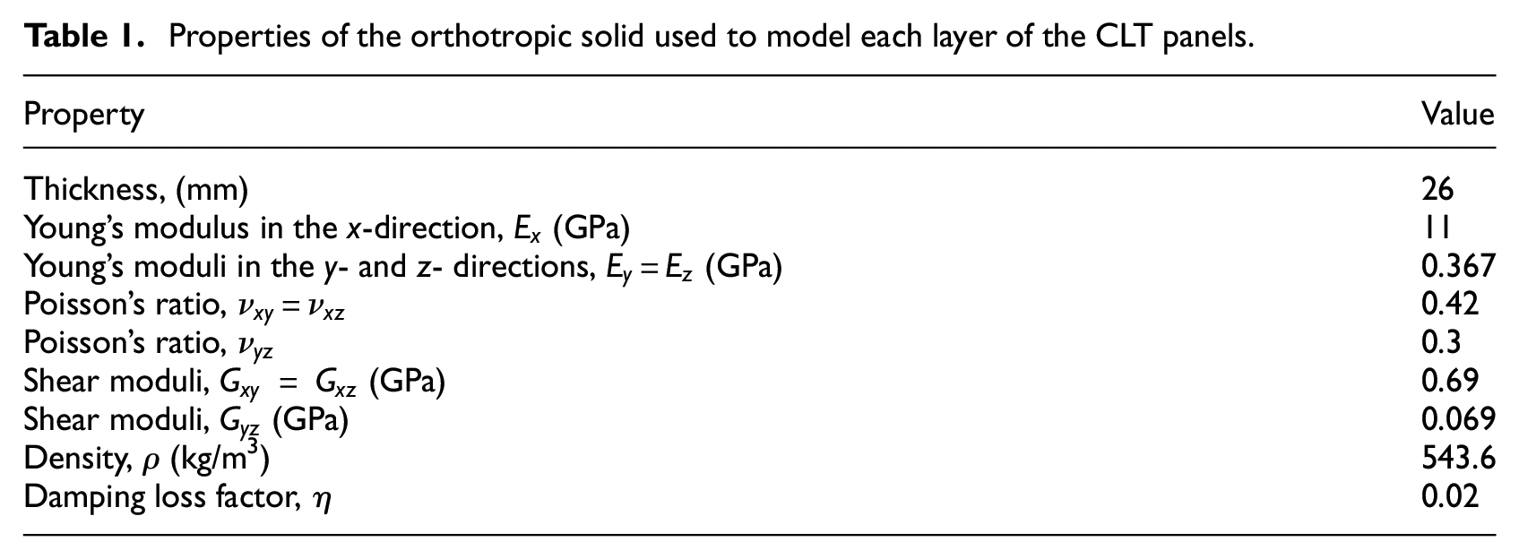
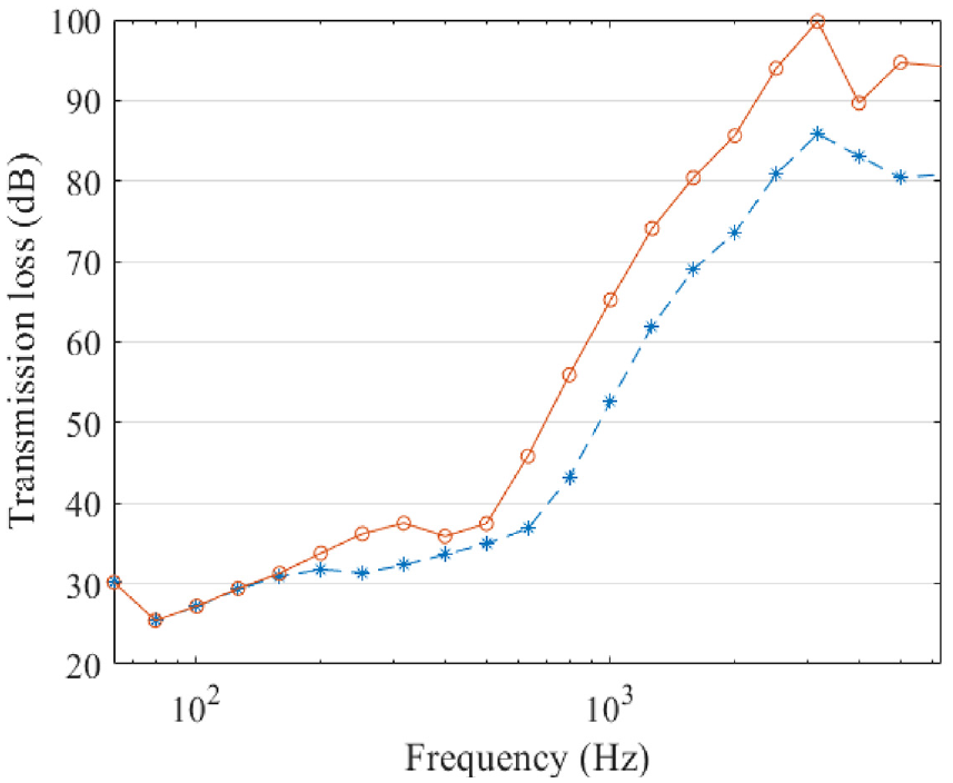
The predicted diffuse-field sound transmission loss spectrum is compared with the experimentally measured data from Hoeller et al. 22 in Figure 6 and shows good agreement considering that the material properties of the timber used in these experiments have been estimated. The predictions show a mass-air-mass resonance dip at approximately 80 Hz (which is in agreement with the frequency predicted using equation (45)). The predictions also show a dip associated with coincidence with the bending wave between 250 and 500 Hz (which is discussed in Yang et al. 7 ) which corresponds with a slight dip in this region in the experimental data.
Diffuse-field sound transmission loss of a double-leaf wall comprising two CLT panels separated by a 25 mm cavity filled with glass wool. WFE prediction (red curve with ○ markers), experimental data (blue dashed curve with * markers).
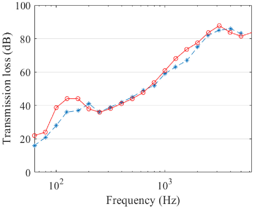
Figure 7 plots the predicted sound transmission loss spectrum for two double leaf CLT walls which are identical to those considered in Figure 6, except that the flow resistivity of the cavity absorbent differs – being
Predicted diffuse-field sound transmission loss for a double-leaf wall comprising two 3-layer CLT panels as leaves separated by a 25 mm cavity. Cavity filled with a porous absorber with resistivity
Also plotted in Figure 7 is a double-leaf CLT wall with a 25 mm wide air cavity. This has been plotted to show that the presence of a porous absorber significantly increases the transmission loss at frequencies between 100 and 3000 Hz compared to a case where an absorber is not used.
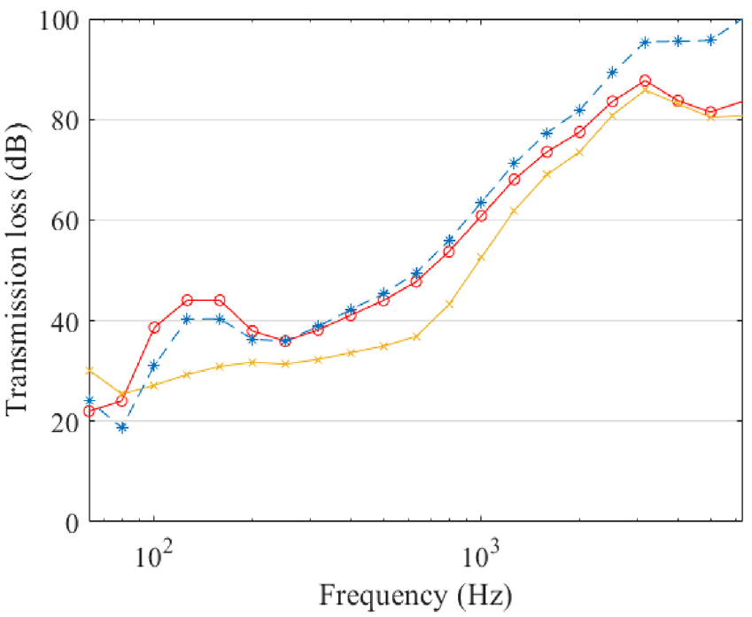
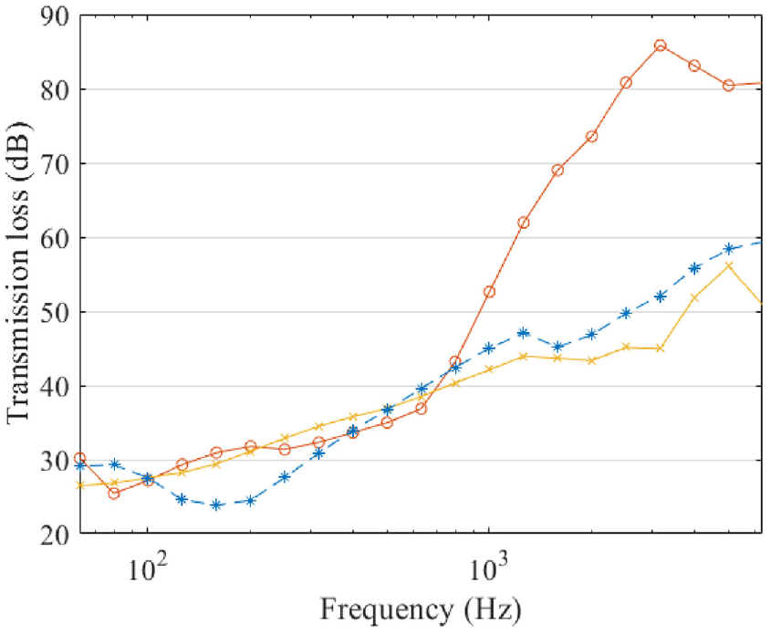
Figure 8 compares the predicted diffuse-field sound transmission loss for three different double-leaf CLT constructions; one with a 25 mm wide air cavity, one with a 25 mm wide cavity filled with glass wool with flow resistivity of 8 kPa.s.m−2 and one with no cavity that is,
Predicted diffuse-field sound transmission loss through a double-leaf wall comprising two 3-layer CLT panels. Wall with a 25 mm wide cavity filled with glass wool (red curve with ○ markers), wall with a 25 mm wide air cavity (yellow curve with × markers), wall with no cavity (blue dashed curve with * markers).
Novel CLT panel constructions
In this section, the WFE method is used to model the diffuse-field sound transmission loss of different wall constructions which utilise CLT panels. Experimental data is not available for these walls and thus the results are meant to be indicative; however, several of the proposed constructions are predicted to have good sound transmission loss performance and may warrant further exploration.
Figure 9 plots the diffuse-field sound transmission loss for three different double-leaf walls each comprising two CLT panels separated by a 25 mm air cavity. The first wall comprises two 3-layer CLT panels, the second wall comprises a 3- and a 5-layer panel (where the 3-layer panel is exposed to the incident field), and the third wall comprises two 5-layer panels. The grain in the outer layers of each double-leaf wall runs horizontally. Each individual layer of the CLT panels is 35 mm thick whilst the other properties of the orthotropic material used to model each layer are given in Table 1.
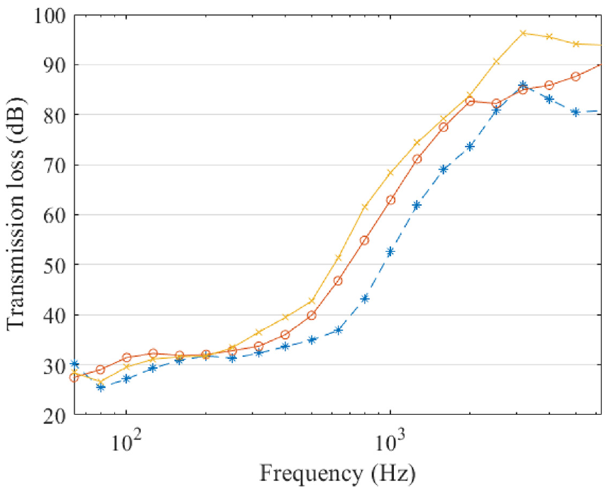
Predicted diffuse-field sound transmission loss through a double-leaf wall comprising two CLT panels separated by a 25 mm wide air cavity. Wall with two 5-layer CLT panels (orange curve with ○ markers), wall with two 3-layer CLT panels (dashed blue curve with * markers), wall with one 5-layer CLT panel and one 3-layer CLT panel (yellow curve with × markers).
All three walls perform similarly at low frequencies. At higher frequencies, the transmission loss of the wall with the mismatched panels performs similarly to the wall with two 5-layer panels; note that both these walls provide an approximately 10 dB improvement in sound transmission loss between 500 and 2000 Hz over the wall with two identical 3-layer panels. The wall with the mismatched panels also has better performance at higher frequencies where a second coincidence effect occurs. 7 This coincidence dip occurs at a lower frequency for the wall with two 5-layer panels in comparison to the wall with the two 3-layer panels. Interestingly, the high-frequency coincidence dip of the mismatched panel is less pronounced and results in an improvement in the sound transmission loss at frequencies above 3 kHz compared with other walls. Presumably, this is due to the fact that both leaves of the panel have different coincidence frequencies which smooths out the total coincidence effect at these frequencies. Similar techniques have been used to improve the sound transmission loss performance of other double-leaf walls – with walls with mismatched leaves producing sound transmission loss spectra with less pronounced coincidence effects. 10 Overall, despite having a lower total mass, the wall with the mismatched panels performs just as well, if not better, than the wall with two 5-layer panels at almost all frequencies.
Asymmetry in the stiffness of the leaves of a double-leaf wall has been shown to reduce the effect of the high-frequency coincidence dip. The CLT panels used to construct the double-leaf walls considered here are made from an orthotropic material and therefore the stiffness of each panel also depends on its orientation. Therefore, the effect of rotating one panel by 90° was investigated. Figure 10 plots the diffuse-field sound transmission loss of two walls comprising two 3-layer CLT panels separated by a 25 mm air cavity. One wall has both panels oriented in the same manner so that the outer layers have their beams oriented horizontally, whilst the other has the leaf on the receiving side leaf rotated 90°. The wall with the rotated panel performs significantly better at frequencies above 200 Hz.
Predicted diffuse-field sound transmission loss through a double-leaf wall comprising two 3-layer CLT panels separated by a 25 mm wide air cavity. Wall with both panels with the outer layers having their beams oriented horizontally (dashed blue curve with * markers), wall with the receiving side leaf rotated 90 (solid orange curve with o markers).
The final case which is considered is that of a wall comprising two 3-layer CLT panels (identical to those considered in Figure 6) separated by a 25 mm thick neoprene rubber layer. The neoprene was modelled as an isotropic elastic material with the following material properties taken from Schaefer
23
and MatWeb
24
: Young’s modulus
Figure 11 plots the diffuse-field sound transmission loss spectrum for this wall and compares it with the transmission loss spectra for a double-leaf wall comprising two 3-layer CLT panels with no cavity, and a double-leaf wall comprising two 3-layer CLT panels with a 25 mm air cavity. The CLT panels of all walls are identical.
Predicted diffuse-field sound transmission loss through several different wall constructions. Double-leaf wall comprising two 3-layer CLT panels separated by a 25 mm wide neoprene layer (yellow curve with × markers), a wall comprising two 3-layer CLT panels with no cavity (dashed blue curve with * markers). A wall comprising two 3-layer CLT panels separated by a 25 mm air cavity (solid orange curve with ○ markers).
Compared to the double-leaf wall with no cavity, the wall with the rubber layer provides improved sound transmission performance between 100 and 500 Hz where the sound transmission loss spectrum of the wall with no cavity has a dip which is attributed to the coincidence effect. However, at higher frequencies, the wall with the rubber layer has similar or lower sound transmission loss performance. However, the double-leaf wall with the air cavity offers significantly improved performance at frequencies above 600 Hz. It should be noted that, like the wall with no cavity, the wall with the rubber layer does not have a dip associated with the mass-air-mass resonance and thus might be preferred for some applications. It should be noted that the approach used here for modelling the rubber layer is quite straightforward and could be extended – for example – using a model which captures how the properties of the rubber layer vary with frequency (such as that described in section 2.1 of Manconi et al. 25 ).
Conclusions
This paper presented a WFE method for predicting the sound transmission loss of double-leaf walls comprising panels of arbitrary complexity separated by a cavity which can contain air, an insulating material or a rubber layer. The method was verified by comparison with results from two analytical models and validated against experimental data from two different independent sources. The predictions show generally good agreement with measured sound transmission loss spectra for most cases.
The focus of this paper was on the application of this method to analysing double-leaf walls comprising CLT panels. To that end, one of the validation cases selected was for such a wall for which the cavity contained glass wool insulating material. The WFE method was found to accurately predict the diffuse-field sound transmission loss spectrum for this wall, including features such as the mass-air-mass resonance and coincidence dips associated with the dominant wavemodes excited within the panels of the wall.
The method was used to investigate the effect of various parameters on the sound transmission performance of a CLT wall construction. In particular, it was shown that the flow resistivity of the glass wool used in the insulating layer of a double-leaf CLT wall has only a small effect on the sound transmission loss spectrum. The sound transmission loss performance of this wall was compared with that of a similar wall with no insulation and also a similar wall with no cavity. It was shown that the wall with insulation performs generally better than the wall with no insulation and that both double-leaf walls perform significantly better than the wall with no cavity at high frequencies. However, the double-leaf walls both produce low sound transmission loss values compared to the wall with no cavity at low frequencies due to the mass-air-mass resonance.
The method was used to explore the potential sound transmission loss performance of several novel double-leaf CLT wall constructions. It was shown that a double-leaf CLT wall with panels of different thickness could produce relatively high sound transmission loss values compared to a slightly heavier wall with panels of equal thickness. It was also shown that the orientation of the CLT panels also affected the sound transmission loss, with a configuration with the panels oriented differently producing higher sound transmission loss than a configuration with the (identical) panels oriented the same way. Finally, the method was used to model the effect of using a neoprene rubber layer in the cavity between the CLT panels. This example serves to demonstrate the usefulness of the method and the ease with which it can be used to model complicated structures. The sound transmission loss of this wall provides an increase in sound transmission loss compared to a wall with no cavity at low frequencies but is significantly worse than a double leaf wall with an air cavity at higher frequencies.
Footnotes
Declaration of conflicting interests
The author(s) declared no potential conflicts of interest with respect to the research, authorship, and/or publication of this article.
Funding
The author(s) disclosed receipt of the following financial support for the research, authorship, and/or publication of this article: Chiaki Fenemore acknowledges funding through the University of Auckland Acoustics Research Centre PhD scholarship. All authors acknowledge the financial support provided by the New Zealand Ministry of Business, Innovation and Employment (MBIE) through a Smart Ideas Grant entitled ‘Predicting Sound Transmission in Lightweight Buildings’.