
Abstract
The dynamic response of building structures is an essential design consideration in building acoustics. However, building design is increasingly driven by sustainability goals. Floors can be optimized to reduce material consumption and corresponding carbon emissions, yet geometric changes may cause sound insulation and vibration problems. Although the dynamic performance of traditional floors is well established, the performance of non-traditional shapes is less understood. Before trusting the results of building simulations encompassing optimized floors, the dynamic results should first be validated experimentally. This paper details a numerical finite element analysis method to ascertain the dynamic response of four shaped concrete slabs, with experimental modal analysis used to validate the numerical results. The material properties in the numerical model are updated to match the experimental results. The findings support a computational framework for determining the dynamic response of shaped structures that can then be implemented in future large-scale building models.
Introduction
The dynamic response of structural elements, especially floors, is an important consideration in building design since it relates to sound insulation and vibration performance.1–5 Humans spend upwards of 90% of their time in buildings, 6 and poor sound insulation has short-term health consequences such as annoyance, 7 sleep loss,8,9 and fatigue.10,11 Worse, failure to have proper sound attenuation can cause occupants to develop long-term health consequences including hypertension and depression. 12 To prevent potential health concerns, building designers need to consider both the air- and structure-borne transmission performance of structural elements. Although air-borne transmission is an essential component of the indoor acoustic environment, 13 structure-borne transmission from activities such as walking have been found to be the “most disturbing noise source,” 14 emphasizing the need to strive for satisfactory impact sound insulation in building design.15,16
Vibrations, a common design concern for building elements,1–3 are often created by a rhythmic force caused by footfall, or machinery, and other transient excitations. If vibrations are not accounted for in design, the floor could be susceptible to amplified displacements, depending on its natural frequency.2,17 If a force excites the natural frequency of the floor, a resonance can occur that could cause human discomfort, and in extreme cases, cause structural damage leading to failure.2,17,18
While favorable dynamic performance of floors is critical to a safe and satisfactory design, building design is increasingly driven by environmental objectives. The construction and operation of buildings accounts for nearly 40% of global energy consumption, 19 and floors made of concrete significantly contribute to embodied carbon emissions when compared to other common structural elements.20,21 One potential solution to reduce the carbon footprint of concrete floors is through reducing material by geometric optimization, since typical floors are designed for ease of construction and thus often overuse material.22–24 Optimized structures can ensure structural integrity while reducing material consumption and corresponding carbon emissions, with possible material savings up to 70%.21–23 Yet lighter, geometrically optimized floors may have adverse effects on the dynamic performance of the structure when they are not properly considered, 25 potentially inadvertently affecting the natural frequency and the sound attenuation.
Previous studies have demonstrated that simulated dynamic results of rectilinear concrete structures can be validated with experimental testing.3,18,26–28 A study by Roozen et al. 29 showed how computational models (e.g. finite element models) can provide accurate simulations of dynamic performance, including phenomena such as sound insulation, of a typology optimized vaulted slab. Yet the numerical findings were trusted only after the model and results were experimentally validated. A later computational study by Wu et al. 30 evaluated the vibration performance of the same typology optimized vaulted slab system, indicating that the computational dynamic study was reliable following experimental validation. Although typology optimized slabs are a solution to reduce material consumption in a floor, many commonly designed concrete systems encompass large ribs. Further, optimized curved ribs can reduce material consumption, but significantly influence the dynamic response of the structure; this behavior has not been researched.
Although optimized structures have a direct environmental benefit, determining their acoustical performance is a challenge. Unlike simple constructions, optimized structural elements cannot presume the same theoretical assumptions when predicting acoustic performance. As mentioned previously, a known strategy to model the dynamic performance of optimized floors is finite element analysis (FEA).3,29–32 Unlike many theoretical approximations, FEA is not restricted to rectilinear structures, since unique geometries can easily be approximated using a mesh composed of hexahedral, pentahedral, or tetrahedral elements. 29 FEA can also account for structures with complicated material properties, such as steel-reinforced concrete elements. 33 These advantages make FEA an appealing option for estimating the dynamics of complex, optimized structures. However, before the results from numerical analyses of shape-optimized structures can be more widely utilized, experimental measurements should be used to validate the dynamic response.
This paper addresses this gap by evaluating the dynamic performance of four unique, quarter-scaled shape-optimized reinforced concrete slabs. First, the shaped slab specimens were designed using nominal reinforced concrete properties. Next, experimental modal analysis using the roving force hammer method was performed on the fabricated slabs. Then, FEA models of the concrete slabs were created using nominal reinforced concrete material properties to estimate the mode shapes and eigenfrequencies. The natural frequencies and mode shapes were then compared to establish the validity of the modeling approach. Modal damping of the slabs, which cannot be easily modeled using FEA, was also determined from the experiments. Finally, the nominal concrete material properties, which naturally exhibit variability, were uniformly updated in the four models to achieve better agreement with experimental results. The following sections include background information on the shaped slabs, the experimental set-up and post-processing, the numerical FEA model, and lastly comparisons of the dynamic results.
Floor selection, geometry, and design
Floor selection
Four unique, quarter-scaled shape-optimized concrete slabs were evaluated in this study. The shapes (shown in Figure 1) were selected to assess the dynamic performance of specimens with known differences in mass density (corresponding to material savings) and simulated air-borne sound insulation calculated for the full-scale specimens. Additional information regarding the air-borne sound insulation methodology can be found in Broyles et al. 34 The Sound Transmission Class (STC) ratings were found to be STC-51, STC-55, STC-60, and an STC-50 for slabs 1–4, respectively. It should be noted that the STC rating only describes the air-borne sound transmission directly through the building element and ignores flanking sound transmission. Although a numerical model approximating STC was used for the slab selection, it was anticipated that the four slabs would have differing dynamic results due to differences in mass density and stiffness. This study focuses on the evaluation of dynamic performance rather than air-borne sound transmission.
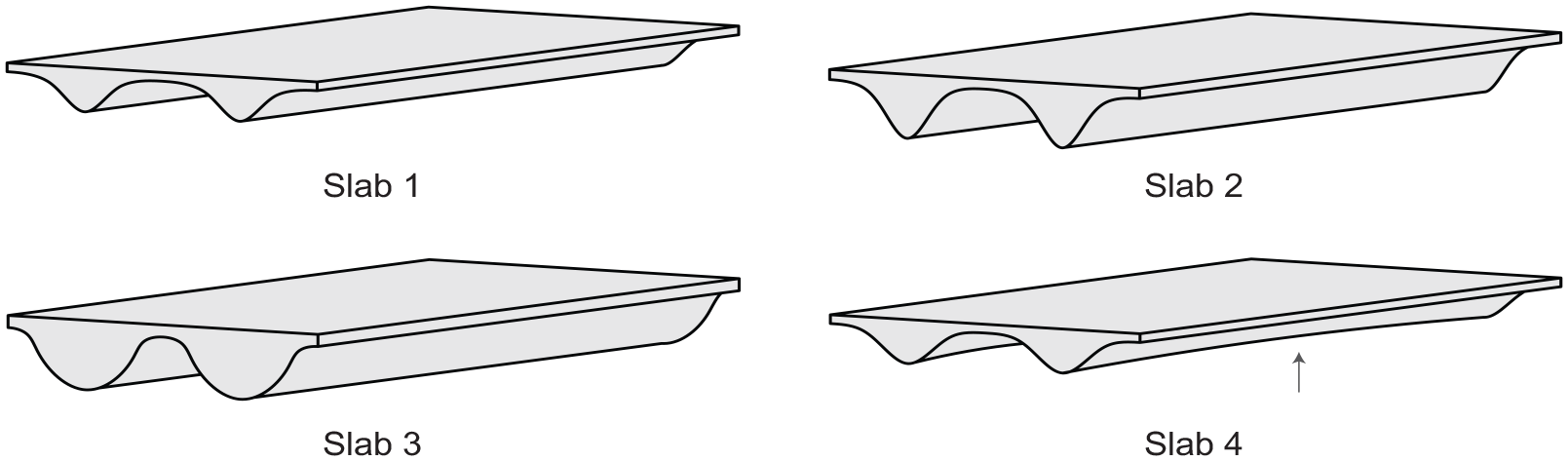
The shapes of the four concrete slabs. An arrow is shown underneath Slab 4 to indicate the difference from Slab 1 (i.e. variation of cross-sectional area along span length compared to uniform cross-sectional area).
Specimen geometry and design
After the four shapes were chosen, computational models for each slab shape were generated using NURBS curves in Rhinoceros3D v. 6. To experimentally obtain the dynamic performance of the specimens, fabrication plans (see Figure 2) were developed for each specimen. Due to scaling, the temperature and shrinkage steel in the top slab was specified as a steel wire grid to limit concrete cracking. Steel-reinforcement was designed at 13 mm (0.5 in) from the bottom of both ribs. The placement of the steel reinforcement and wire was the same for slabs 1–3, but the reinforcement for slab 4 was located about 26 mm (1.0 in) from the bottom of the rib ends to accommodate the curvature across the length of the rib.
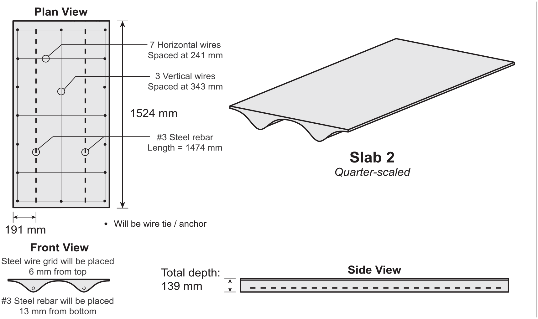
Fabrication plans for a representative shaped steel-reinforced concrete slab.
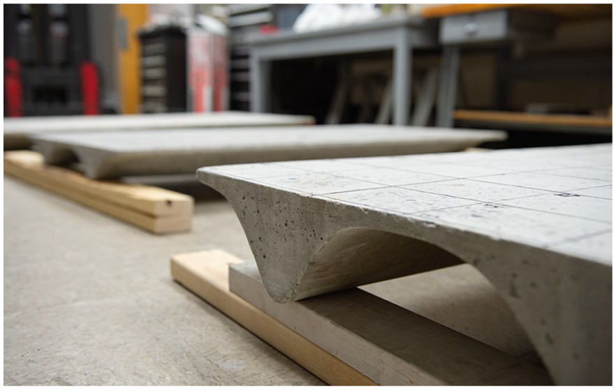
The floor slabs are essentially a one-way slab with the ribs “shaped” to improve acoustical and sustainable performance. Since they are unconventional geometries within a parametric design space of possibilities, several can begin to look like a Double “T” shape. However, they would be analyzed structurally as one-way slabs as long as they maintain the dimensional requirements for this analysis. Each design had top slab dimensions of 762 mm × 1524 mm (2.5 ft × 5 ft), with varying top slab and rib depths, as noted in Table 1. Each slab contained two ribs, which would span the narrow side of a building, with multiple slabs placed next to each other. Slabs 1, 2, and 3 had a uniform rib cross section across the length of the slab. Slab 4 had rib curvature that varied across the slab length, but the ends of the ribs had the same cross section profile as slab 1. The mass and mass densities of the quarter-scaled specimens are also provided.
Geometric properties of the four quarter-scaled slabs.
Normal strength concrete was specified for the slab models, with a modulus of Elasticity, Ec of 29,721 MPa (f′c of 5.8 ksi), and a steel reinforcement strength of 210,000 MPa (30,450 ksi). The concrete floor models presented in this work are designed to resist the same structural load, corresponding to typical ASCE 7-10 35 floor requirements scaled to the experiment. Further details of the structural design and performance can be found in Broyles et al.34,36
Although a flat slab specimen was not fabricated nor experimentally tested in this study, the flat slab that would be designed according to the structural conditions specified would have a uniform thickness of 230 mm (9 in). A quarter-scale specimen would thus have a uniform thickness of 57.5 mm (2.25 in), with a total mass of 163 kg (360 lb). Slabs 1 and 4 would have a mass savings (which corresponds to a more sustainable design) compared to the flat slab of 26.3% and 29.4%, respectively. Slab 2 would have marginal mass savings, while Slab 3 would have an increase of mass of 54.0%. However, Slabs 2 and 3 would likely have better air-borne sound transmission performance compared to the flat slab. Experimental modal analysis and numerical validation has been previously conducted on RC flat slabs,37,38 however, a direct comparison to the slab specimens in this paper would require maintaining the same specimen scale, concrete mix, specimen fabrication, and experimental procedure. Such a comparison could be performed in future work.
Experimental procedure
Specimen fabrication
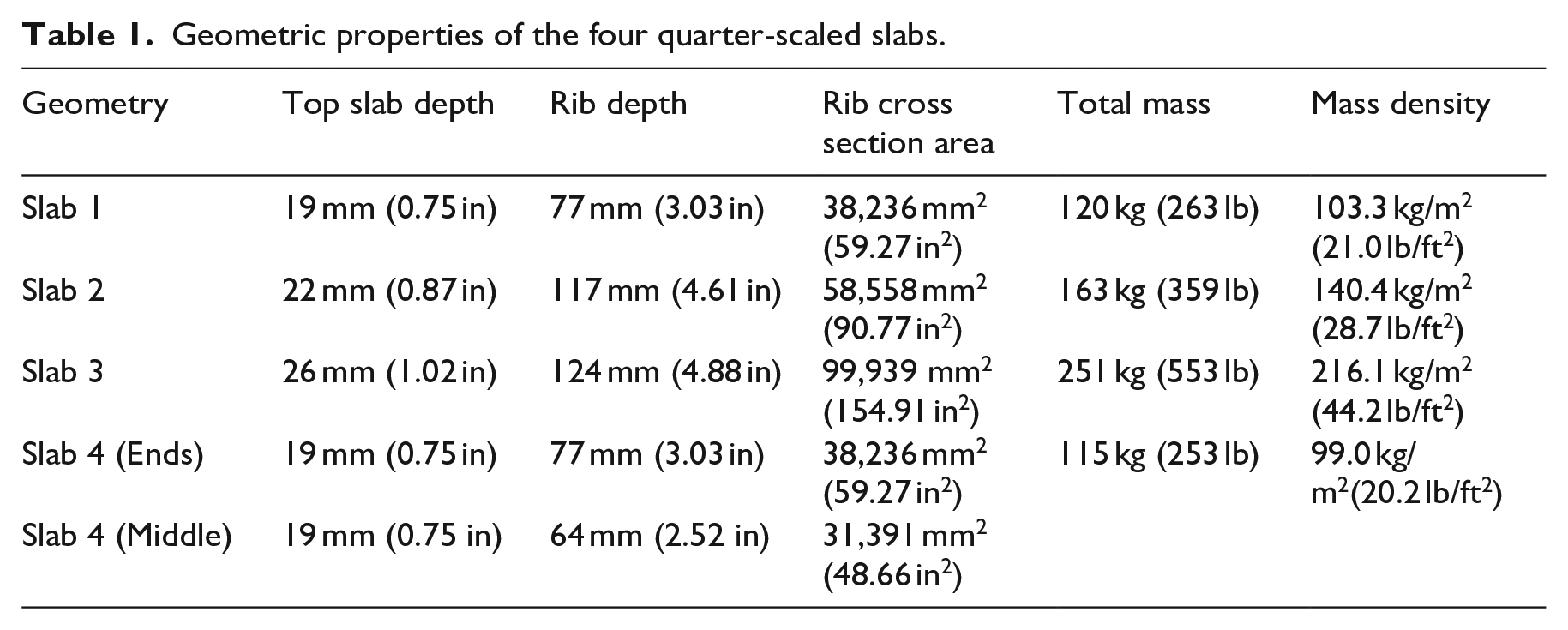
Following numerical modeling, the four shaped slabs were fabricated using a normal concrete mix of cement, water, sand, and pebble-sized aggregate. The surface of the formwork was created by bending sheet metal to follow the curvature of the ribs. The sheet metal was held in place by plywood supports cut into the cross-section shape at increments along the slab length. Steel reinforcement was then placed inside the form. After the wet concrete was poured, the specimens remained in place until curing finished (i.e. after 28 days). Since the shaped concrete specimens were poured explicitly for testing (i.e., no structural load other than the slab self-weight was applied), it is assumed that the specimens had not cracked, which was confirmed by inspection. One of the scaled specimens is shown in Figure 3.
The fabricated specimen from the design of slab 2.
Testing of structural properties
To validate the material properties of the four concrete specimens, the concrete strength was verified by breaking concrete cylinders with a diameter (D) of 102 mm (4 in) and a height of 203 mm (8 in) from the same mix used for the slab specimens. A uniaxial compressive test following ASTM C39 39 was conducted on three concrete cylinders on the 28th day from the concrete pour. The rupture load (Pmax) was found for each cylinder, as shown in Table 2. The rupture load (reported in kN) is then used to approximate the compressive strength of concrete (f ′c) in MPa,
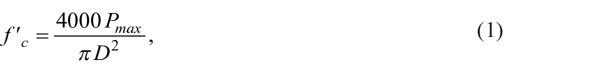
which is used to determine an initial static modulus of elasticity of the concrete (Ec) in MPa:

The rupture load for three concrete cylinders with the corresponding material properties.
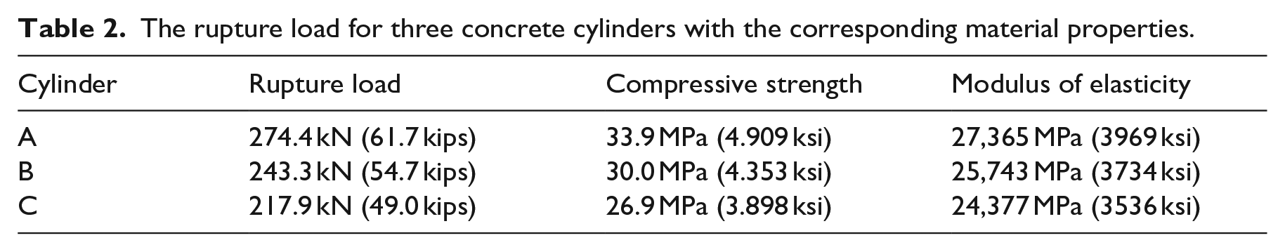
After testing, the three concrete cylinder compression test results were found to have an average compressive strength of 30.3 MPa and a standard deviation of 3.5 MPa. The initial material properties used in the numerical FEA slab models were an Ec, of 25,871 MPa (f ′c of 30.3 MPa) with a Poisson’s ratio of 0.15, and a steel modulus of elasticity, Es, of 210,000 MPa with a Poisson’s ratio of 0.30; however, due to the variability found in the structural tests, it was deemed necessary to evaluate the FEA models for other structural material property combinations.
Modal test set-up
For each specimen, four accelerometers were attached to the top surface using wax. The surface was then excited using the roving force hammer approach at the points shown in Figure 4(a) and (b). Four Winbags (see Figure 4(c)) were used to create a “free-free” boundary condition. The Winbags were inflated with air and placed under the ends of both ribs. Although the Winbags rested on the ground, the air created a free-free condition to isolate the slabs under a force load without significantly influencing the recorded modal response.
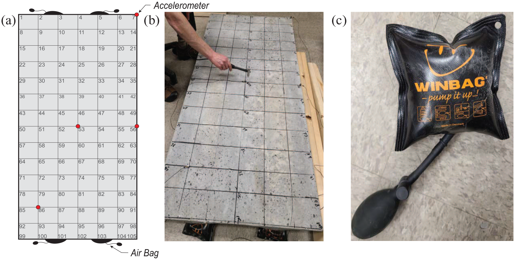
Experimental set-up for the roving hammer method: (a) the grid showing the locations of the hammer impacts on the top slab of each concrete specimen. (b) A picture during the experimental testing. (c) Four Winbag supports were positioned on the ends of both ribs to replicate free-free boundary conditions.
Each grid point was excited three times and averaged to reduce noise in the FRF measurements. 40 The frequency response functions (acceleration over force) were acquired with a National Instruments PXI system sampling at 10,240 Hz with a blocksize of 16,384. Due to the anti-aliasing filter within the system, the usable bandwidth was 0–4 kHz, with a frequency resolution of 0.625 Hz.
Experimental data post-processing
Experimental modal analysis was performed on the four slabs to obtain its mode shapes, natural frequencies, and modal loss factors. This analysis was based on the roving hammer exciting the structure at regular grid points, with the response captured by the accelerometers. The accelerometers were attached in the normal direction to the flat side of the slab to obtain acceleration to force frequency response functions (FRFs) for each excitation point (see Figure 5).
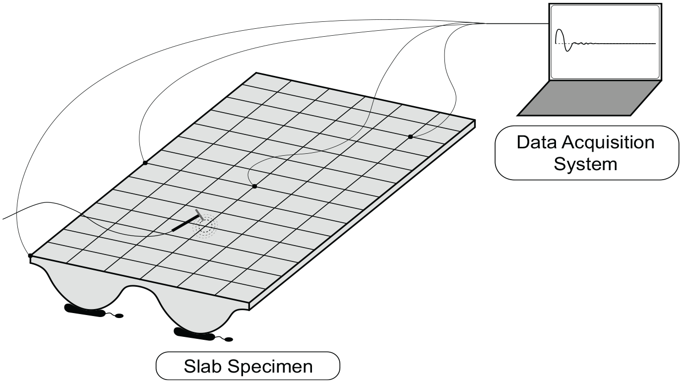
Experimental data obtained through the roving force hammer method was post-processed.
The matrix of FRFs, referred to as

with the matrices
Numerical FEA model
Geometric model and meshing
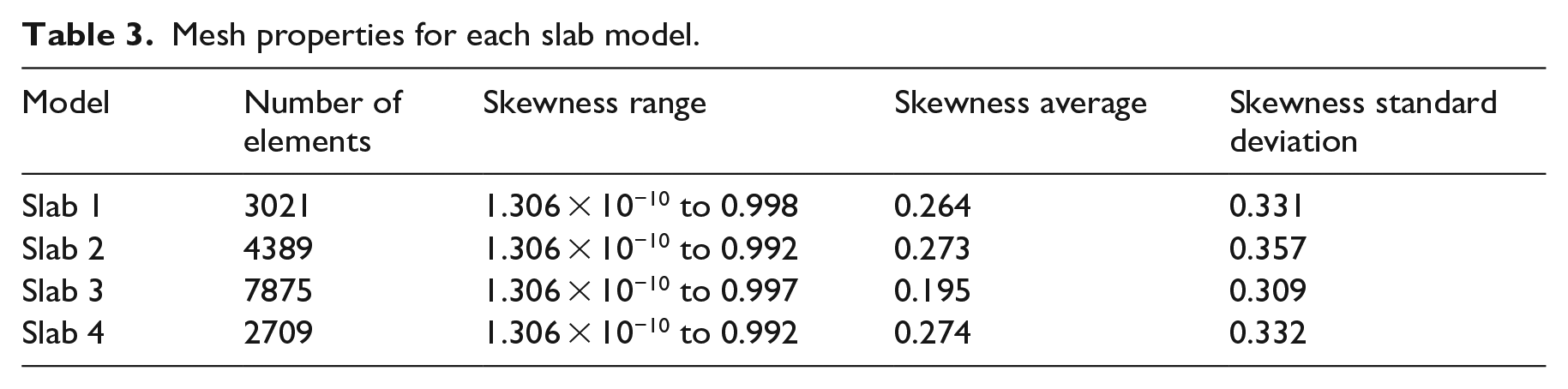
The slab geometry files were imported into ANSYS (v. 2021 R1) to conduct the finite element analysis, with a unique mesh generated for each slab. The top slab was modeled using solid hexahedral elements with an average width, depth, and height of 25 mm, and the ribs were modeled using a combination of hexahedral and tetrahedral elements with a base of 25 mm, due to the curved geometry. To ensure that the slab models had an adequate mesh, the skewness, which is a unitless measure that accounts for the mesh quality, 42 was assessed for each shaped slab. Table 3 presents the range, average, and standard deviation of the mesh skewness for each slab model. Skewness ranges from 0 to 1, with a smaller number corresponding to a better mesh quality. The meshes were deemed satisfactory based on 84% of the finite elements having a skewness value at or below 0.630 for each slab, which is below the maximum skewness of 0.95 recommended by ANSYS.
Mesh properties for each slab model.
Steel reinforcement and model pre-processing
Since steel reinforcement was placed near the bottom of both ribs for each slab design (Figure 6), two strips of elements were selected within each mesh to have steel reinforcement properties after the shaped slab was meshed. These steel elements were centered in each rib at a height above 25 mm. Although the exact steel reinforcement geometry can be incorporated in FEM, this approach simplified the numerical model by reducing the number of solids that needed meshing, reducing computational cost. This approach enables the concrete and steel elements to have element nodes and faces aligned.
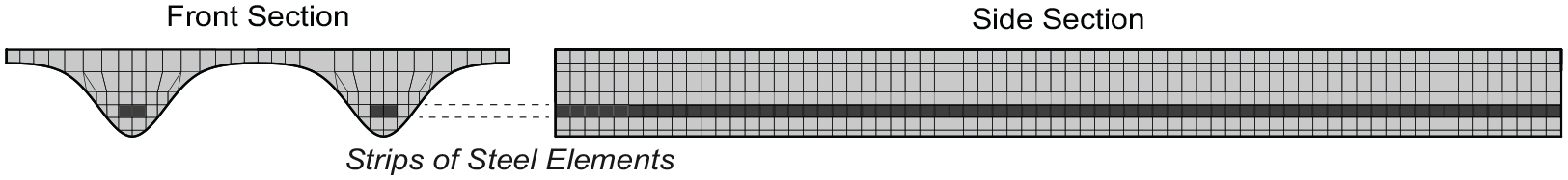
Two strips of elements were selected for steel reinforcement, as shown in the model of slab 2.
After specifying the steel reinforcement elements, the first 40 modes and eigenfrequencies were found for each slab. The boundary conditions were modeled as free-free to match the experimental set-up described previously.
Results and discussion
This section compares the initial numerical and experimental modal response of the four slab specimens, systematically evaluates the geometric properties in the numerical model for validation, and then discusses broader applications from the provided results and limitations.
Initial result comparison
Figure 7 shows the mode shapes and eigenfrequencies obtained for each slab after post-processing the experimental data. The first four mode shapes are characterized as (1,1), (2,0), (0,2), and (2,1) and are consistent across all slabs. The mode order switches for slabs 2 and 3, which is expected since the different slab and rib depths (See Table 1) create different ratios of bending to torsional stiffnesses. The natural frequencies of the modes, except for the (0,2) mode, still increase with weight as seen by slab 4 (the lightest panel) having the lowest frequency and slab 3 (the heaviest panel) having the highest frequency.
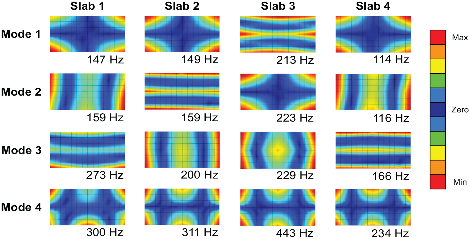
The first four experimentally obtained mode shapes for each slab specimen. Red represents both the maximum positive and maximum negative displacement of each mode while blue represents zero displacement.
The modal damping for the four slabs is compared in Figure 8. Damping loss factors were estimated using the poly-reference technique previously mentioned. The values fall roughly around 0.01 and are mostly consistent between the slabs. The variation increases slightly above 1 kHz and is mostly pronounced in slab 1. This suggests that the damping of the concrete slabs at lower frequencies does not strongly depend on the rib shape, but damping may have some influence at higher frequencies.
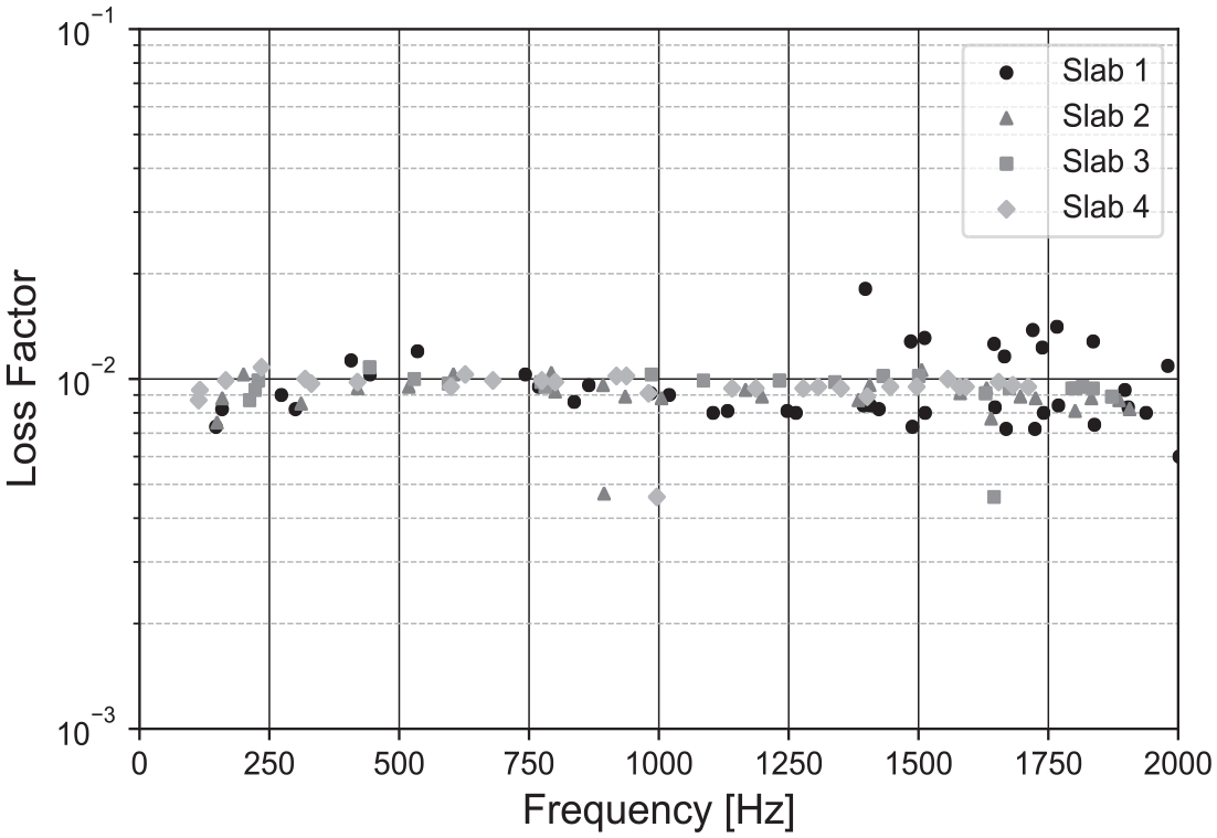
Modal loss factors for the four slabs.
The experimental results are compared to the initial numerical results in Figure 9. The mode shapes match well overall, but the measured natural frequencies are higher than predicted. Since the numerical and experimental masses are nearly identical (see Figure 10), the initial comparison reveals that the concrete modulus in the numerical models is too low. Therefore, a comprehensive sensitivity analysis that varied the material properties was conducted to identify the material properties that best matched the experimental results.
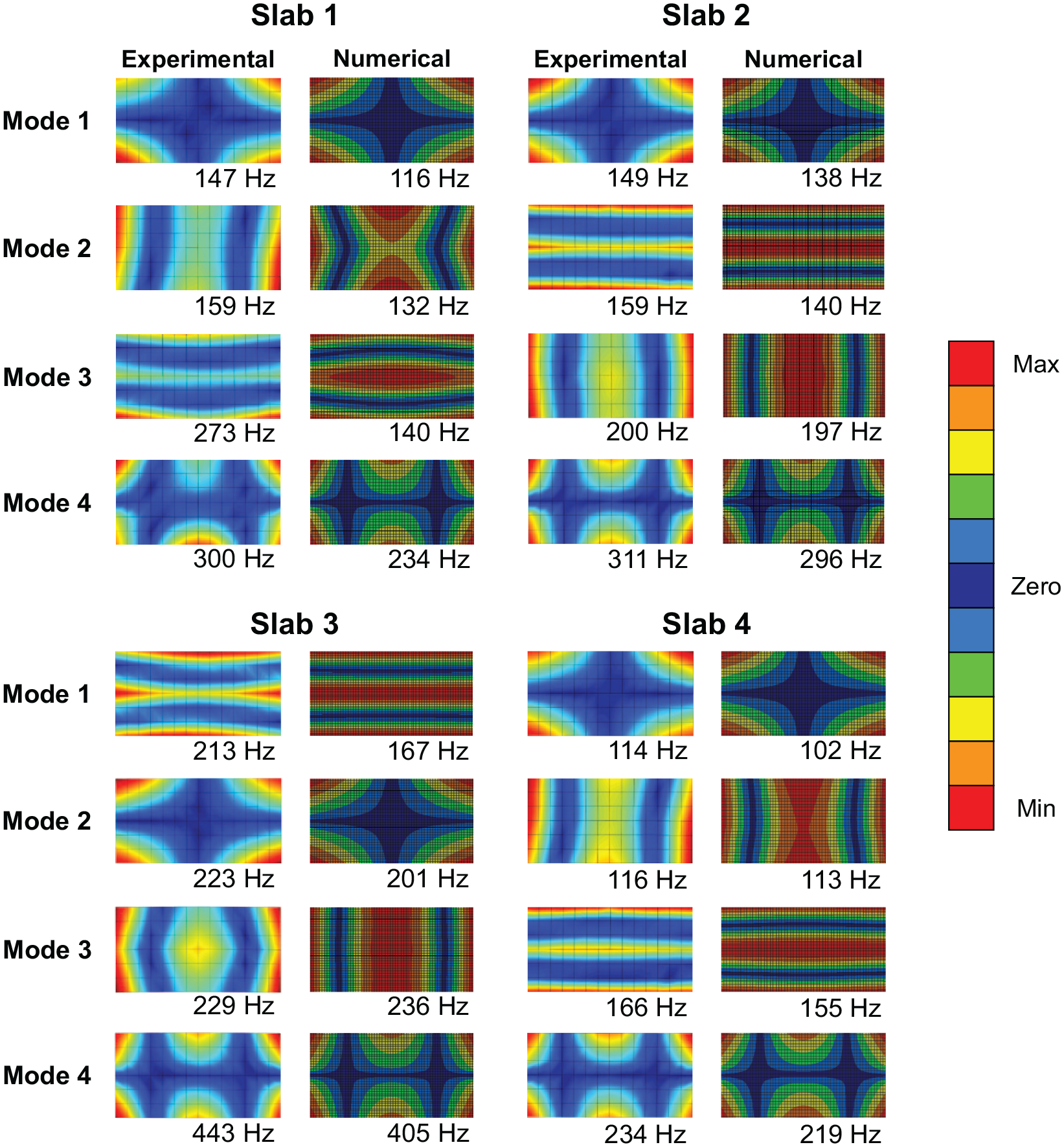
The initial mode shape comparison of the experimental and numerical model results.
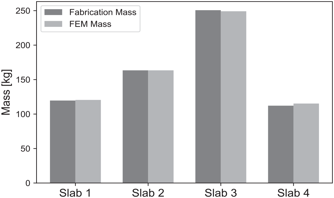
Comparison between the fabrication and modeled mass of the four slabs.
Material property exploration
After the experimental results were obtained, the material properties in the FE models were systematically explored to minimize the error with the experimental results. The material properties that were varied included the concrete compressive strength from a range of 37.92 to 48.26 MPa (5.5 to 7 ksi), which corresponds to a modulus of elasticity of 28,943–32,652 MPa, and a Poisson’s ratio from a range of 0.10 to 0.20. In sampling to find the smallest percent error, the numerical modes were matched to the first 16 experimental modes for each grouping of material properties. The percent error between the natural frequency of each mode shape pairing was taken and then averaged across the 16 mode shape pairings. The composite percent error for each material property combination is shown in Figure 11. In the contour plot, the light color corresponds to low percent error while the dark color corresponds to high percent error.
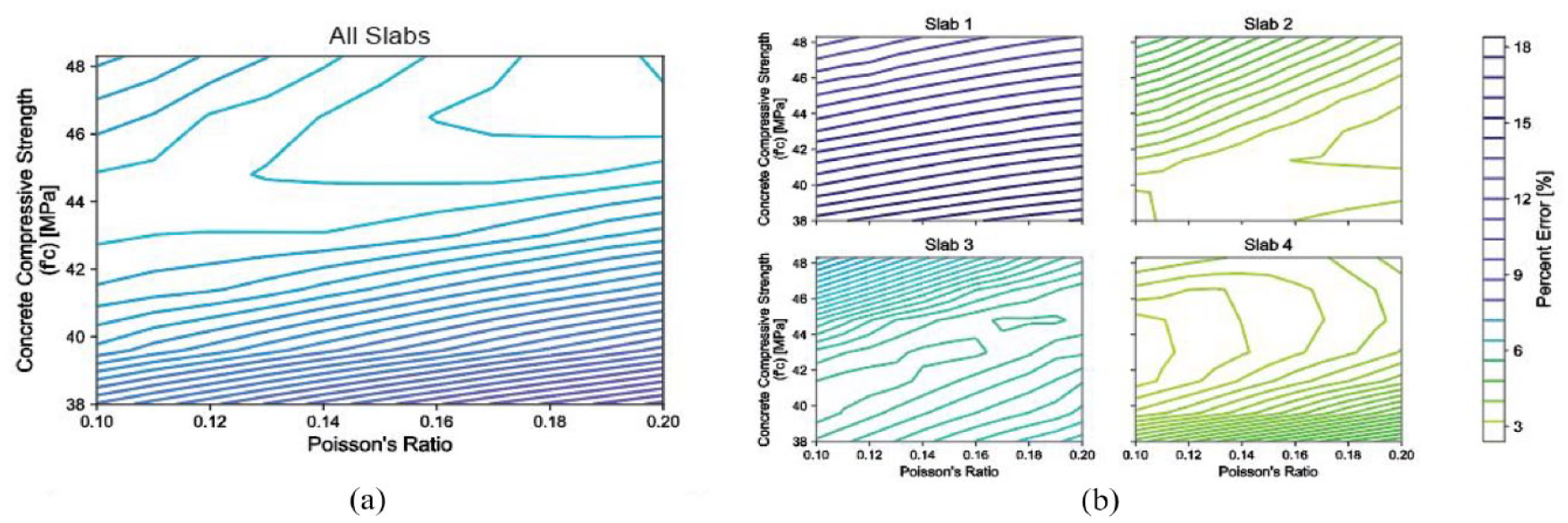
(a) A contour plot showing the averaged percent errors for the four slabs to ascertain the material properties, and (b) contour plots for each slab.
The composite percent errors were averaged across the four slabs to identify the material properties that work best for all slabs. The lowest composite percent error was 6.75% using the material property combination of a modulus of elasticity of 32,064 MPa (f′c of 46.54 MPa) and a Poisson’s ratio of 0.18. This grouping of materials was selected to obtain the final modal performance.
Final validation
Figure 12 displays the contrast between the experimental and numerical natural frequencies for each slab. Slab 1 has the worst correlation of numerical to experimental eigenfrequencies, with lower numerical frequencies at frequencies at, and above, 1 kHz. Similarly, slab 3 had poor correlation above 1 kHz, but had good correlation below 1 kHz. Slabs 2 and 4 match very well with little percent error across all 16 mode shapes.
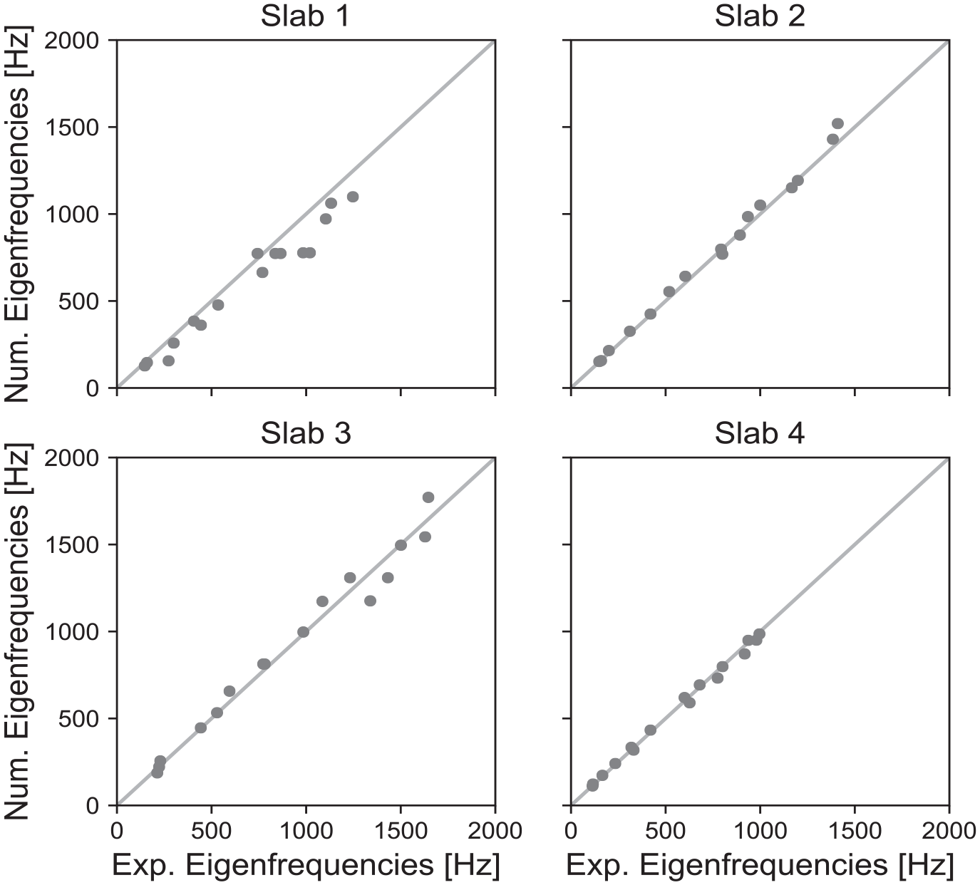
Comparison of the experimental and numerical eigenfrequencies.
Similar results are found from the Modal Assurance Criterion (MAC) between the experimental and numerical mode shapes for the four slabs. The MAC is defined as,
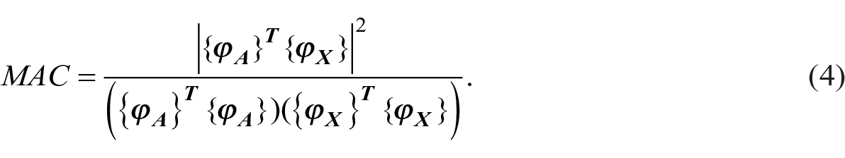
where {
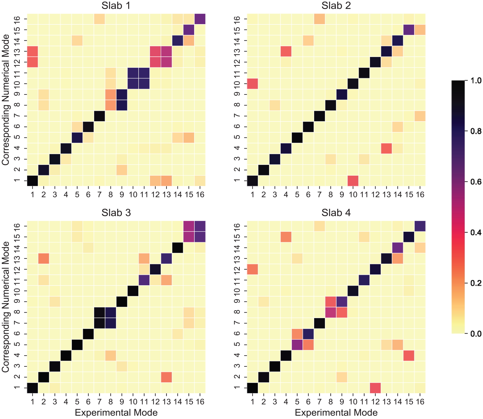
The MAC for each slab for the first 16 experimentally obtained mode shapes.
The modal damping factors that were experimentally obtained were used in the numerical model to determine the dynamic response, as seen in Figure 14. The drive-point mobilities were obtained with an excitation point at grid point 1 (for reference, see Figure 4(a)) and a reception point at grid point 7. It should be noted that the anti-resonances shown correspond to minimal dynamic responses in between modes. In the numerical model, the equivalent viscous damping is applied as a constant value. Experimental values for the damping were needed due to the lack of a predictive damping model for shaped concrete specimens.
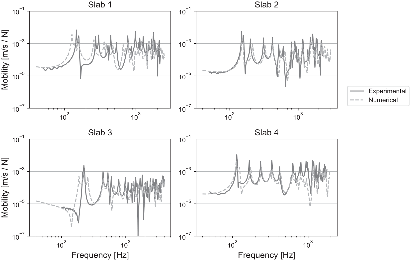
The drive-point mobilities of each specimen given an impact force at the corner of the slab.
Discussion
The previous figures show good agreement between experimental and numerical results. However, there are multiple factors of uncertainty that should be noted. First, concrete material can vary from pour to pour even when using the same concrete mix. Although the ASTM C39 39 standard was followed, previous research has reported significant variations in concrete material properties.45,46 Second, while the placement of the steel rebar was located near the center of each rib, slight imperfections can create uncertainty in the numerical results. Finally, human error is a factor in all fabrication and experimental measurements, leading to small uncertainties. Since the accuracy of the comparison between measurement and model is not entirely consistent between the four slabs, it seems that the uncertainty could be design specific. Nevertheless, the results from this paper provide helpful insight on the dynamic performance of shaped floors, validating the numerical FEA approach used.
Implications in building acoustics
Validating the modeling procedure of shaped concrete specimens promotes many research opportunities in the field of building acoustics. Primarily, future researchers can implement the method demonstrated here to explore the dynamic performance of other uniquely shaped building elements. The structural geometry can be coupled to optimization frameworks aimed at increasing the sound insulation or improving the fundamental frequency. Furthermore, FEA could be implemented as a decision-making tool to determine if optimized structures are acoustically advantageous compared to traditional building elements. Wall elements, which have been shown to have favorable acoustical performance when optimized, 47 can also be assessed using the proposed method.
Further experimental research should be conducted on shaped structural elements. For instance, a study determining the dynamic modulus of Elasticity of different shaped specimens would be valuable for further dynamic analysis. A structural four-point bending test would also help validate the expected structural performance of these specimens. Experimental studies encompassing other building disciplines would give insight on the holistic performance of optimized floors.
This study also encourages the expansion of full-scale shaped slab specimen models. 48 The eigenfrequencies of the full-scale models could be compared to the experimentally obtained eigenfrequencies. A ratio of four-to-one would be expected from the quarter-scaled specimens. Although full-scale models have high computational costs, full scale numerical models could aid designers in finding the fundamental frequency of an entire floor or building. 49 Full-scale models are also necessary to further understand the behavior of optimized structures. 50 For example, the vibration performance caused by rhythmic loads, such as those experienced from a machine or human activity (i.e. walking), can be assessed to determine if vibration control measures are required. The computational results could be compared to a conventional flat slab to further study the influence of the shaped slabs.
Another research application is to determine the sound insulation performance of the bare shaped slabs. Using a simplified injected force of 1 N normal to the top (flat) side of the slabs, the modal frequency response can be found. A single impulse that excites a broad frequency range would be preferable as simulating rhythmic forces at many locations using FEA is computationally costly. The drive point impedance can be generated from the force and used to calculate the input power. The transmitted radiated sound power can then be calculated by determining the pressure along the pressure at the boundary of a free-field air hemisphere, as was explained by Broyles et al. 51 This strategy can help designers consider the impact sound insulation performance of different shaped structural elements in the conceptual design stage. A related subject to sound insulation is the coincidence frequency of a structure. Previous work by Broyles et al. 52 found that the shape of concrete specimens can influence the frequency that the coincidence dip occurs in simulated transmission loss. Further, optimization techniques can improve air-borne performance of slabs by shaping the rib to have a coincidence frequency below the 125 Hz one-third-octave band. In a secondary study, alternative sound insulation metrics more appropriate for optimization were proposed. 51 Later studies that optimize structural elements in buildings, like walls, should similarly study the coincidence frequency.
Additional areas of future research include the incorporation of room acoustic modeling techniques, such as raytracing, to determine the holistic acoustical performance in the building. Shaped ceilings have shown that geometric alterations can improve the acoustics in a room 53 ; however, sound insulation was neglected from this study. Incorporation of floating floors or hung ceilings is another avenue for future research. Similarly, assessment of the absorptive performance of non-traditional structures may be valuable for designers to explore alternatives for improving room acoustics. 54 Lastly, incorporating accurate acoustic objectives can aid in multi-disciplinary studies aimed to determine the overall best performing designs. 55
Conclusion
This paper presents a numerical model that was validated through experimental measurement of four shaped concrete specimens. An FEA model was created for the four slabs to ascertain their dynamic performance, with the numerical model results validated by experimental data. The numerical model was adjusted to minimize the percent error with the experimental modal response. Such validation is crucial before evaluating shape-optimized structures in larger numerical building analyses, especially for further optimization that incorporates acoustical objectives such as impact sound insulation and vibration control.
Footnotes
Appendix A
Acknowledgements
The authors are grateful to Anand Swaminathan, Jonathan Boliek, Thomas Burtnett, and Mike Houser for their help with the fabrication and transportation of the concrete specimens. The authors would like to thank Kelby Hochreither for photographing the concrete slab specimens.
Declaration of conflicting interests
The author(s) declared no potential conflicts of interest with respect to the research, authorship, and/or publication of this article.
Funding
The author(s) received no financial support for the research, authorship, and/or publication of this article.