
Abstract
Harnessing tribochemical reactions at sliding interfaces has been proposed to provide an alternative perspective for manufacturing well-defined nanostructures for applications other than tribology. This approach provides a new notion of employing tribology to create nanofilms for applications such as micro/nanoelectromechanical systems (MEMS/NEMS). In this study, the ball-on-disc mini traction machine (MTM) was used to manufacture conductive tribofilms by using the 3-Aminopropyl triethoxysilane (APTES) as a precursor. Different rotation speeds were applied to evaluate the tribofilm growth at different lubrication regimes, including boundary and mixed regimes. The results confirmed the ability to manufacture thick tribofilm using APTES on steel surfaces. Tribofilm characterisation using Energy Dispersive X-Ray Spectroscopy (EDS) and Transmission Electron Microscopy (TEM) confirmed the tribofilms’ formation and thickness. The film thickness of APTES reached up to 300 nm compared to 100 nm of ZDDP tribofilm without damaging the contact surface. The AFM analysis showed the conductivity of the formed APTES tribofilm compared to the nonconductive ZDDP tribofilm.
Introduction
Manufacturing small electronic devices, electrically conductive and miniaturized, requires complex and advanced manufacturing technologies. 1 These techniques enable the production of conductive layers at the nanometer scale on device surfaces.2,3 The electronic devices include gyroscopes, nozzles, bio/chemical sensors, micro relays, pressure sensors, microchips, rotation sensors, accelerometers, and nanotube-based devices.1,3–5 Tribo-based techniques to manufacture nanofilms have been introduced as a potential method for applications in electronic devices.6,7 Some recent studies6,8,9 have explored the manufacturing of tribofilm that formed during the tribological process, to functionalise the surface for small electronic devices that require high precision. The tribofilm in these applications can play a crucial role in protecting the surface and providing conductivity for electrical components in small sizes.6,8–10 Recent studies, including Yin et al., 11 Parra et al. 12 and Marian et al., 13 have studied MXene-based composite coatings. The results revealed the formation of nanostructure tribofilms, which contribute to a remarkable improvement in wear and electrical properties.
The lithography patterning techniques are the most common method to manufacture conductive electronic circuits in real applications.4,14 It applies the focused electron beam on targeted materials to promote chemical reactions to fabricate film on the surface. This method is used to build up the conductive film on flexible and rigid substrates.4,5,14 Recently, a tribo-based technique has been introduced to functionalise surfaces and interfaces through building up tribofilm at the sliding interfaces.6,8,9 The atomic force microscope (AFM) method has been used to manufacture patterns on the surface.6,8,9 For instance, Dorgham et al. 6 reported a novel method of using AFM to manufacture organic and inorganic tribofilms (≈100 nm) on silicon and steel substrates. The study was conducted successfully to grow tribofilms under varied test conditions. Similarly, Gosvami et al. 9 studied several mechanisms that influence the growth of tribofilm under sliding contacts of AFM single asperity. The growth rate of tribofilm was correlated to the sliding cycles, contact pressure, and temperature. However, the complexity, time, and cost of the lithography and AFM techniques are still the drawbacks and limitations of film manufacturing for electronic circuits.
The Zinc Dialkyl Dithiophosphate (ZDDP) fluid additive is a well-established antiwear additive. Its ability to form durable nanoscale tribofilms is shown to be essential for its performance.15–17 In recent years, ZDDP has been used as a precursor material for manufacturing 3D film on the surface6,8 with potential application in areas other than tribology. The manufactured film of polyphosphates, due to the decomposition of ZDDP, results in a thick film of around 100 nm. ZDDP film excels in mechanical and thermal properties, therefore it is introduced to be used as a film precursor for 3D film manufacturing technology. 18 However, ZDDP tribofilm is found to be nonconductive. 19 To functionalise the manufactured ZDDP tribofilm, Duston et al. 8 integrated graphene nanoplatelets into a ZDDP tribofilm. As a result, the carbon-rich layer was formed above the pure ZDDP layer, enhancing the tribofilm conductivity. 8 Not much is known about whether the conductivity of the film could be obtained by using conductive materials, such as conductive polymer compounds, as film precursors. 20
Polymer-based compounds have been used in some applications to form self-assembled monolayers.7,19,21–23 For example, the 3-Aminopropyltriethoxysilane (APTES), a self-assembled monolayer, reacts chemically to the contact surfaces to generate a bonded film.7,21–23 The APTES has been added to the fluid formulation to improve the dispersion of nanoparticles within lubricants. APTES in the fluid formulation is considered an environmentally safe additive and a nontoxic material. 24 Hafeez et al. 24 revealed the formation of the APTES layer on the intrinsic silicon (i-Si). The APTES layer was deposited on the Si substrate using plasma-enhanced chemical vapor deposition (PECVD). The chemical structure of the APTES layer revealed the existence of −Si, −C = O, and −NH2 functional groups. The APTES thin layer was formed to enhance the efficiency of solar cells. Miranda et al. 25 applied salinization to deposit APTES thin film on the silicon oxide substrate. Han et al. 26 successfully produced monolayer and non-uniform multilayer films of APTES on the surface using the silanization method, the thickness of the APTES layer was correlated to the silanization time. 26 However, APTES has not been investigated before as a precursor material to form 3D nanostructures using sliding interfaces.
This study aims to develop conductive 3D nano-scale films by using APTES as a tribofilm precursor. Its ability to form a film has been compared to ZDDP, which is used as a reference. Furthermore, we will introduce an alternative fast and cheap approach to manufacturing tribofilms, utilizing multi-asperity contact surfaces instead of the AFM-based tribofilm method.
Materials and methods
Materials
The Polyalphaolefin (PAO4) fluid was utilised in this study as a solvent, with two different additives of ZDDP and APTES used as tribofilm precursors. Two mixtures, including PAO + 10 wt.% ZDDP and PAO + 10 wt.% APTES, were prepared using a hot plate at a speed of 500 rpm and room temperature for 30 min. The concentration of 10 wt.% was selected to ensure sufficient additives for manufacturing a thick film on the surface. There are no restrictions on the concentration of the additives in this study as the focus is on building up tribofilm rather than reducing friction and wear. The APTES (3-Aminopropyltriethoxysilane
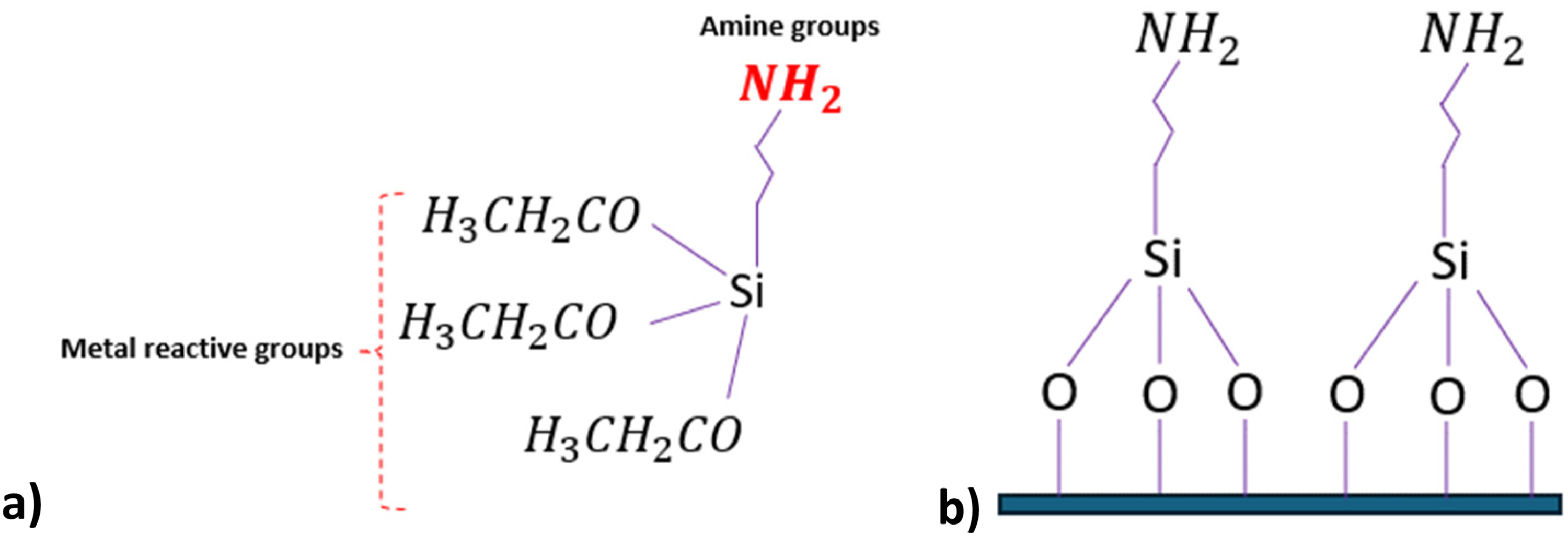
(a) Schematic representation of the chemical structure of APTES molecules, (b) APTES molecules attached to the metal surface to form the monolayer.
Tribofilm formation technique
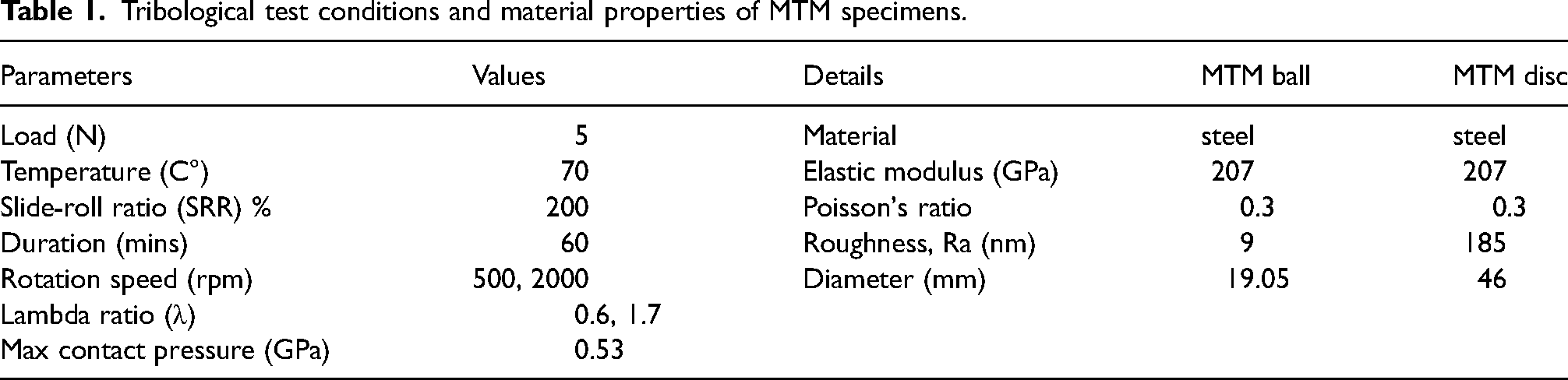
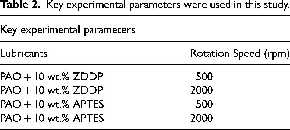
MTM tribometer, as schematically shown in Supplementary Figure S1, was used to test the film-forming properties of the tested fluids. The material properties of test specimens and test conditions are reported in Table 1. The test conditions are selected with two different rotation speeds of 500 and 2000 rpm to create two different lubrication regimes. The contact interfaces are in boundary with a lower speed (Lambda λ = 0.6) and mixed regime with a higher speed (Lambda λ = 1.7). The maximum contact pressure was 0.53 GPa. The test conditions are carefully designed to evaluate tribofilm manufacturing in two lubrication regimes. The MTM tests are repeated at least two times to ensure the repeatability of tests. The key experimental parameters are summarised in Table 2.
Tribological test conditions and material properties of MTM specimens.
Key experimental parameters were used in this study.
Post-surface analysis
An optical white light interferometry (NPFLEX) was conducted to analyse the surface after tribological tests. In this study, the NPFLEX technique analysed wear in the contact surfaces to find out if the tribofilm is associated with high wear. The surfaces of MTM discs were scanned across the rubbing area by NPFLEX and the obtained images were processed using Vision64 software from Burker Ltd, USA. Moreover, the surface analysis of the wear scar of MTM discs was carried out using the Scanning Electron Microscopy (SEM) technique. The SEM analysis provides high-resolution images of the surface damage and tribofilm formation on the rubbing area. Energy Dispersive X-ray Spectroscopy (EDS) was conducted to detect the chemical element composition of the formed tribofilm on the MTM disc. The SEM/EDS is the first step in proving the existence of tribofilms on the surface before further investigating the manufactured films.
Tribofilm conductivity using AFM
The conductivity of the tribofilm for two precursors of ZDDP and APTES was measured using conductive atomic force microscopy (CAFM, Bruker, USA). An area of 0.5 × 2 µm2 inside the rubbing area was scanned with a scan rate of 1 kHz, an aspect ratio of 1, a speed of 10
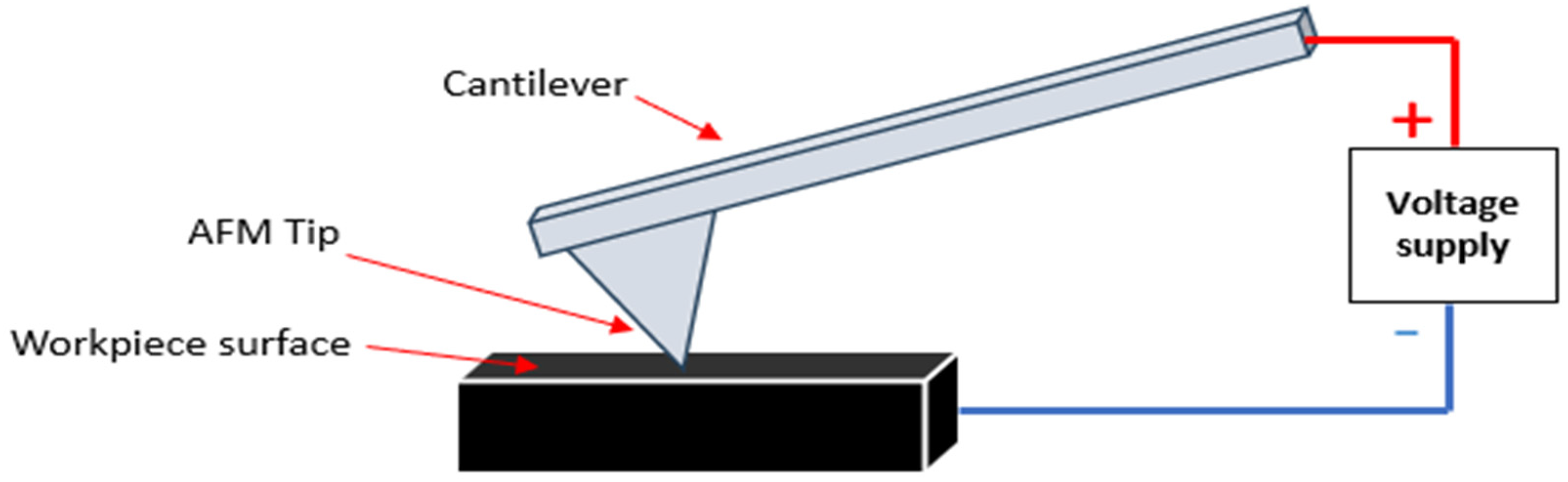
Schematic of the CAFM used to measure the electrical properties of the sample surface, which was applied through the surface to analyse the conductivity of manufactured tribofilm.
Film cross-section analysis using transmission electron microscopy/focussed ion Beam (FIB)
The internal structure of formed tribofilms, produced from the tested materials, was analysed using the TEM-FIB technique. The FIB (FEI Helios G4 CX Daul beam) was used to create a slice on the tribofilm. The cross-section of tribofilms was analysed using TEM/EDS (FEI Titan Themis 300) mapping to observe the thickness and elemental distribution of the tribofilms.
Results and discussion
The manufacturing of tribofilms using two tested fluids is demonstrated in this section. Since tribofilm formation process is driven by potential tribochemical reactions, it is important to present first the friction as an indication of the energy input in the interface. Followed by NPFLEX results to measure wear and detect any material loss from the substrate. As there were signs of film formation which were visually observed, the SEM/EDS analysis was further conducted to prove the tribofilms formation on the surface. After the manufacturing tribofilms, TEM-FIB analysis is used to characterise tribofilms properties including thickness and chemical distribution of films. Finally, the C-AFM technique is used to measure the conductivity of manufactured films.
Effect of APTES tribofilm on friction
The tribological tests of two different fluids of PAO + 10 wt% ZDDP and PAO + 10 wt% APTES were carried out at two different entrainment speeds. The friction results are reported in Figure 3. For the PAO + 10 wt% ZDDP sample (Figure 3(a)), the friction coefficient starts high at the first 10 min of running the test and stabilises to the end of the test. At the end of tribological tests, the average friction coefficient at a low speed of 500 rpm is approximately 0.11 compared to 0.07, which is the friction coefficient for a higher speed of 2000 rpm.
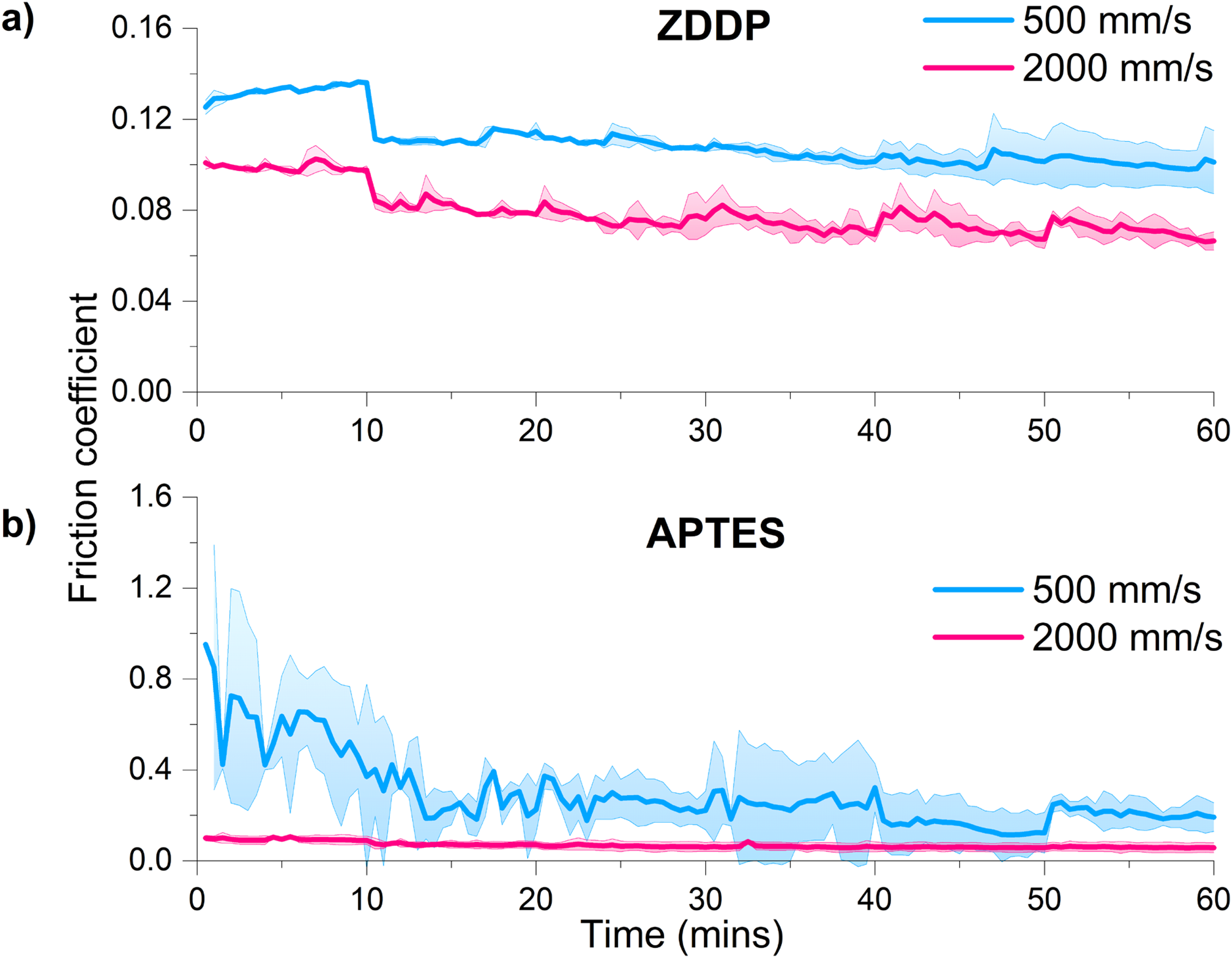
Friction results of PAO + 10 wt% ZDDP (a) and PAO + 10 wt% APTES (b) at different speeds of 500 and 2000 mm/s. The blue curves represent the friction curves at low speed (500 mm/s). The red curves represent the friction curves at high speed (2000 mm/s).
Initially, the friction coefficient is as high as 1.0 for the PAO + 10 wt% APTES sample (Figure 3(b)), which reduces over the test period. The high and fluctuating friction coefficient was observed for the APTES sample at low speed. The friction coefficient for the APTES fluid sample at high speed shows a lower and constant friction coefficient compared to the friction at a lower speed. The average friction coefficient at 500 rpm is approximately 0.2 compared to 0.06 at 2000 rpm. At the high speed of the APTES fluid test, a more stable and lower friction coefficient was observed.
As observed in previous studies28,29 regardless of the additive types in lubricants, the reduction in friction at higher sliding speeds is associated with the transition in the lubrication regime from boundary to mixed regime (Figure 3). Furthermore, another factor that could affect friction is that the growth of ZDDP tribofilm thickness increases the friction at higher rotation speeds. This is due to an increase in the extended running distance, causing higher friction. 30 As there are no previous works about APTES tribofilm formation and its correlation to friction, the authors suggest that at low speed, a stick-slip phenomenon contributes to high and fluctuating friction values until 25 min of test duration. While at high speed, it is worth noting that the differences between minimum and maximum friction points during the test are very small, and the average friction coefficient tends to stabilize. The significant decrease in friction (Figure 3(b)) at high speed compared to low speed is due to the transition from stick-slip to only smooth sliding. It is also due to the transition from boundary regime to mixed regime at high speed, reducing the direct contact between the interfaces. The differences in average friction values at two speeds provide a good indication that energy input to overcome interfaces is changed due to modifications in film properties. This similar trend, stick-slip behavior, which is influenced by speed, was mentioned in previous studies.31–33
Manufacturing of tribofilm protective films
Surface analysis using NPFLEX for the MTM discs was performed to indicate if the formed films protect the substrate during the rubbing of the surfaces. The 3D surface images combined with the surface profiles of the scanned surfaces are reported in Figure 4. The surface images (Figure 4(a), (b), and (d)) indicate no damage caused after the tribology test for all fluid samples, excluding the PAO + 10 wt% APTES sample at a speed of 500 rpm (Figure 4(c)). The surface images show scratches on the surface originating from sample manufacturing, as demonstrated in Figure 4(a). The wear profile of the PAO + 10 wt% APTES fluid sample at low speed demonstrates deformation of the surface in the wear track (Figure 4(c)). The surface analysis of rubbing areas of the tested fluids of PAO + 10 wt% ZDDP (at 500, 2000 rpm) and PAO + 10 wt% APTES (at 2000 rpm) shows no noticeable damage. This suggests the formation of a protective film on the surface acts to reduce the material loss from the substrate. To know more about the existence of the APTES and ZDDP tribofilms, a detailed SEM and EDS analysis was performed, as given in the following section.
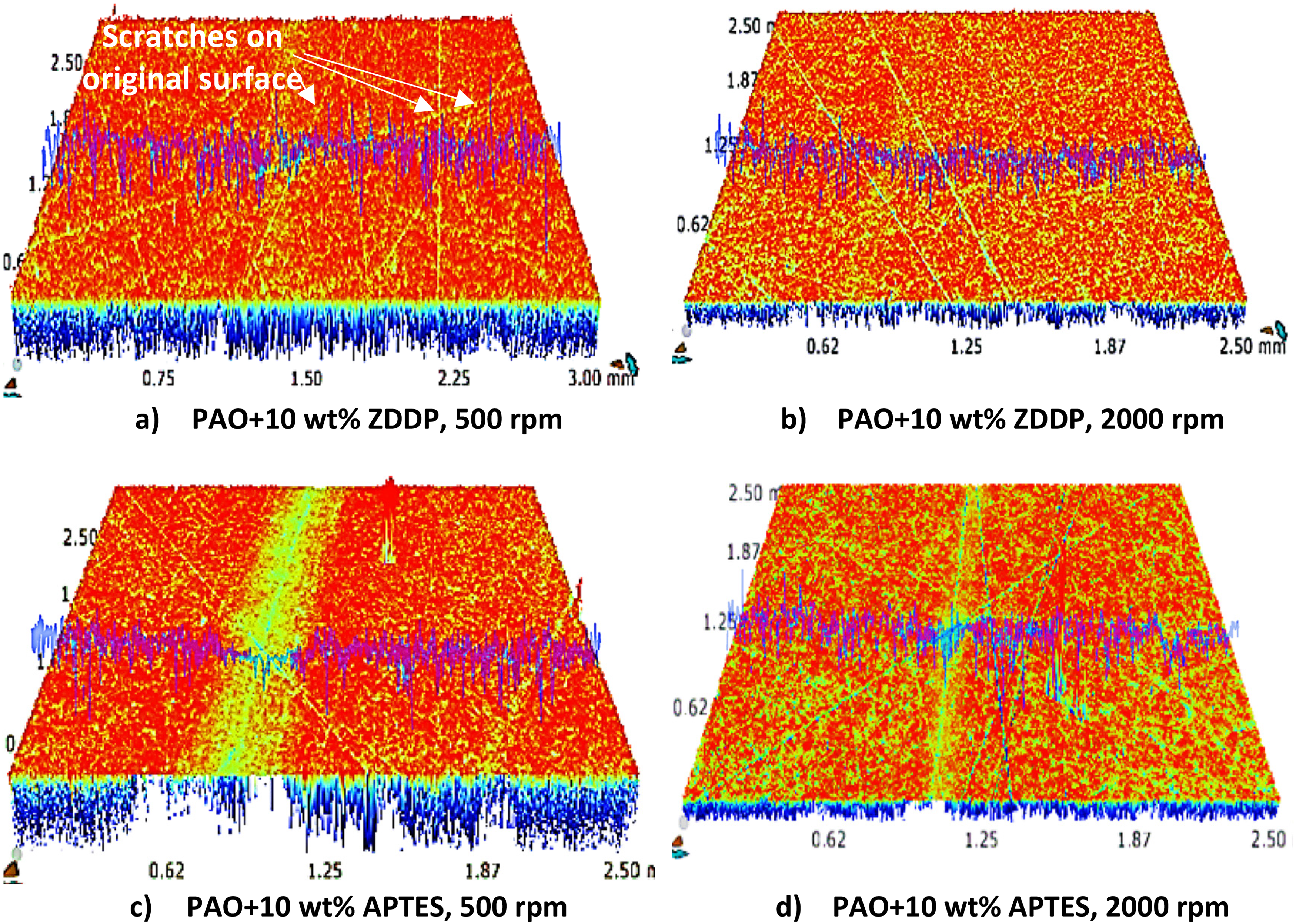
NPFLEX surface analysis for MTM discs after tribological tests for the following samples (a) PAO + 10 wt% ZDDP at a speed of 500 rpm, (b) PAO + 10 wt% ZDDP at a speed of 2000 rpm, (c) PAO + 10 wt% APTES at a speed of 500 rpm, (d) and (d) PAO + 10 wt% APTES at speed of 2000 rpm.
Figure 5 shows the SEM image and a representative EDS spectrum from each wear scar of tested MTM discs. Surface analysis of PAO + 10 wt% ZDDP fluid at a speed of 500 rpm is presented in Figure 5(a). The results reveal no damage or lost materials in the contact area apart from the scratches from the original surface sample. The dark area on the surface represents the sliding area of interface contacts. Chemical analysis using EDS inside and outside the wear track was performed as shown in Figure 5a1. Figure 5a1 shows the existence of ZDDP tribofilm elements (Zn, S, and P) identified in spectrum 1, compared to the absence of the tribofilm elements outside the wear track in spectrum 2. The absence of significant damage on the interface area with the presence of ZDDP key elements from the ZDDP additive indicates the formation of ZDDP tribofilm on the surface, which is used as a reference. A similar SEM/EDS analysis was carried out for PAO + 10 wt% ZDDP at a speed of 2000 rpm, illustrated in Figure 5b, b1. The main observation is no damage on the contact surface. The EDS data confirms the presence of ZDDP elements (Zn, S, and P) inside the wear track, with a slightly higher elemental concentration compared to the same sample conducted at a lower speed, as shown in Figure 5a1, b1. It is important to highlight that SEM/EDS for this sample was carried out after TEM-FIB analysis. This can explain the existence of the Pt element in the spectra, which comes from the sample preparation process.
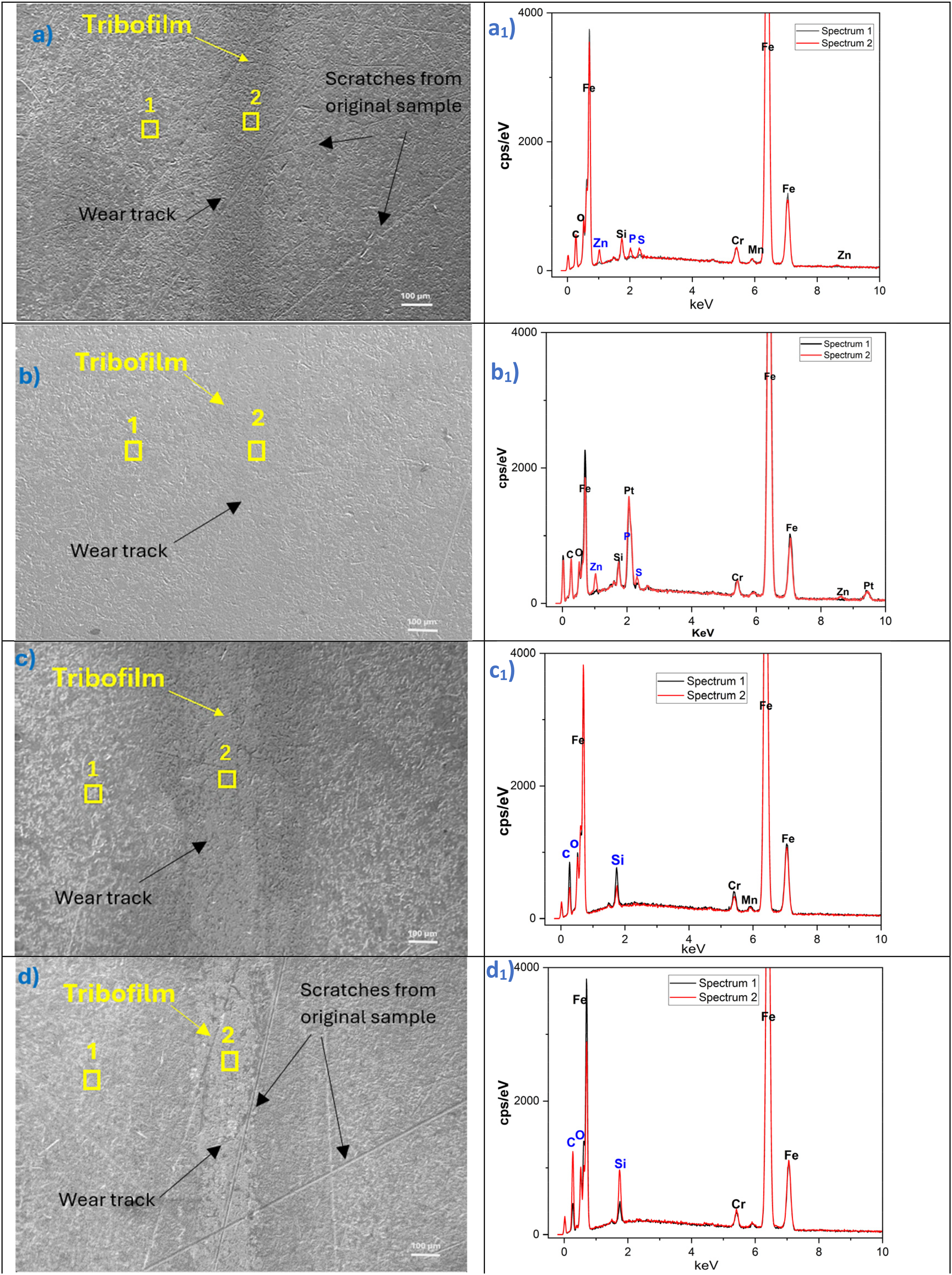
SEM/EDS analysis for sliding contacts and outside the rubbing area of MTM discs (a) (a1) SEM image and EDS data for the PAO + 10 wt% ZDDP, 500 rpm test, (b) (b1) SEM image and EDS data for the PAO + 10 wt% ZDDP, 2000 rpm test, (c) (c1) SEM image and EDS data for the PAO + 10 wt% APTES, 500 rpm test (d) (d1) SEM and EDS data for the PAO + 10 wt% APTES, 2000 rpm test.
For the fluid sample of PAO + 10 wt% APTES at a speed of 500 rpm, the surface analysis of sliding contacts shows no apparent damage other than the deformation of the rubbing area. The APTES tribofilm (darker color) was observed on the sliding area as shown in Figure 5(c). Chemical analysis of APTES tribofilm indicates the increase in the elemental concentration of
Cross-section analysis of manufactured tribofilms
The SEM-EDS analysis confirmed the existence of the APTES and ZDDP tribofilms manufactured on the substrate by analysing the distribution of tribofilms’ elements, as reported in Figure 5. The chemical analysis using TEM cross-section provides insights into the detailed mapping of nanostructure across manufactured films. The spatial resolution of TEM-EDS for ZDDP tribofilm shows the distribution of
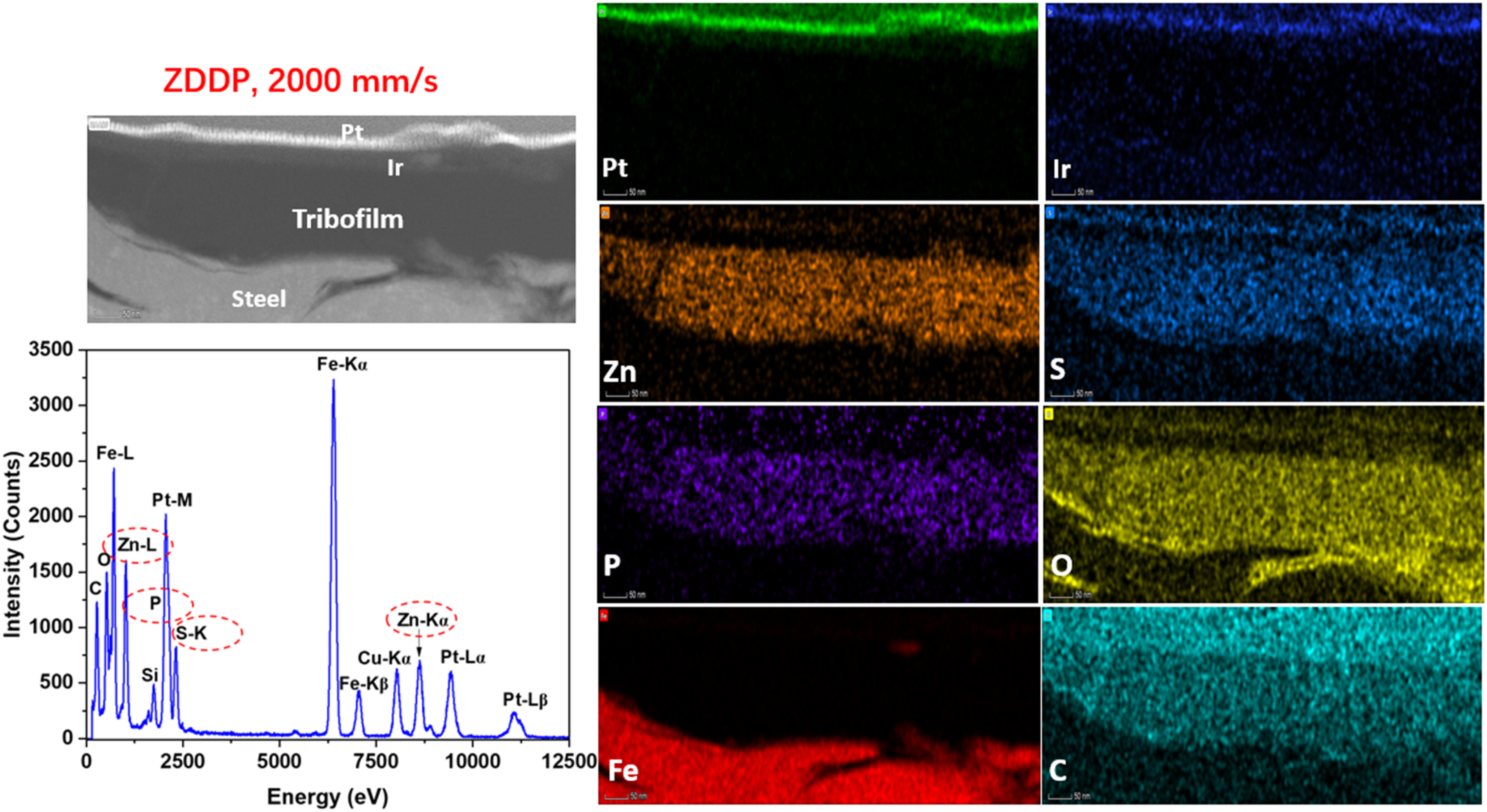
Chemical analysis of ZDDP tribofilm on the MTM disc using TEM-FIB for the PAO + 10 wt% ZDDP, 2000 rpm sample. The spatial resolution of TEM-EDS for ZDDP tribofilm shows the distribution of Zn, S, P, C, and O elements throughout the tribofilm section.
The chemical analysis across the depth profiling of APTES tribofilm is presented in Figure 7. The TEM-EDS of APTES tribofilm reveals the presence of three primary elements
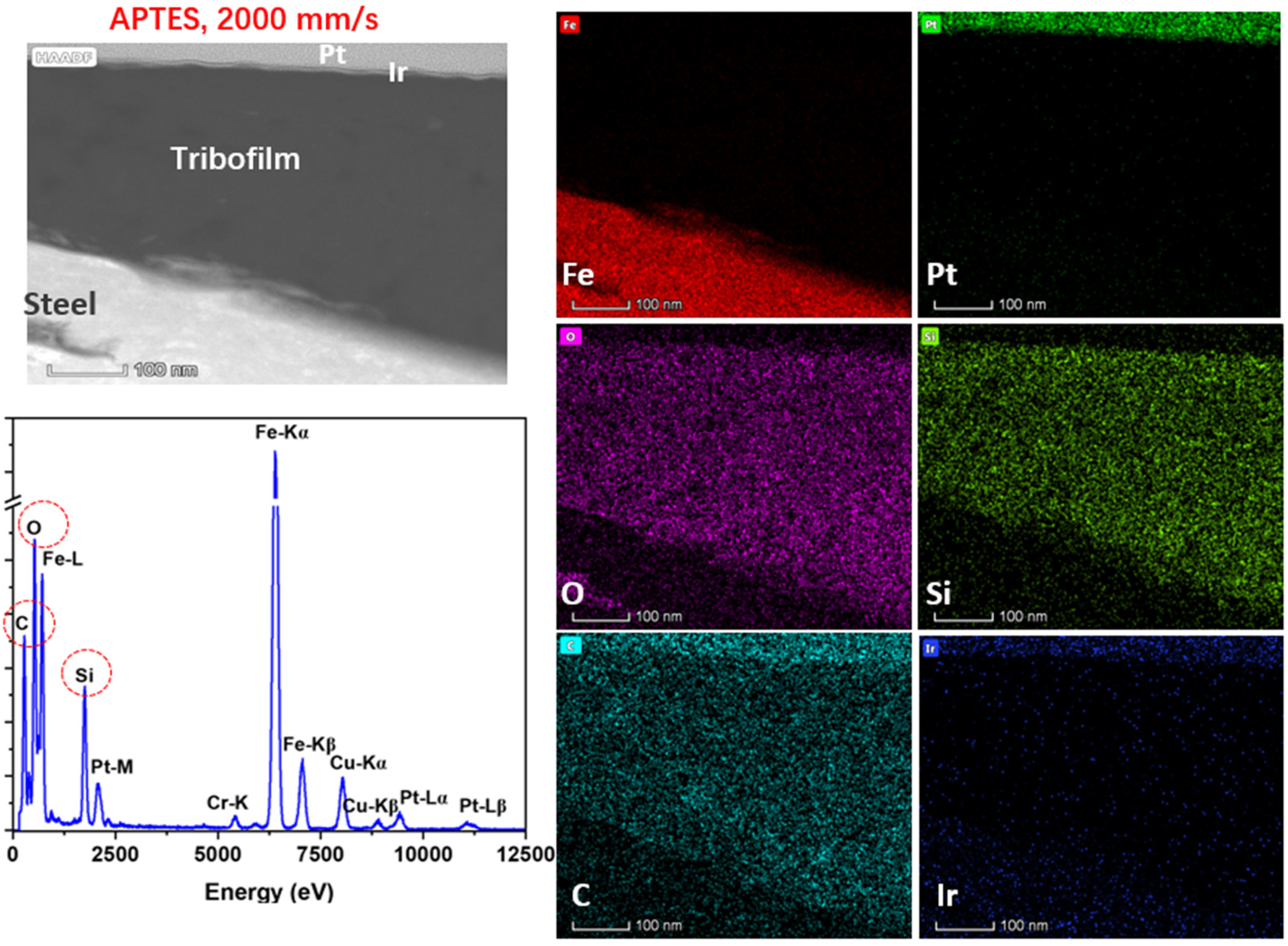
Chemical analysis of APTES tribofilm on the MTM disc using TEM-FIB for the PAO + 10 wt% APTES, 2000 rpm sample. The spatial resolution of TEM-EDS for APTES tribofilm shows the distribution of C, Si, and O elements throughout the tribofilm section.
The TEM-FIB technique was used in this study to evaluate the thickness of ZDDP and APTES tribofilms. The PAO + 10 wt% ZDDP fluid at a speed of 500 rpm demonstrates the tribofilm thickness of ≈60 nm as shown in Figure 8(a). At the higher speed of 2000 rpm, the PAO + 10 wt% ZDDP fluid reveals higher tribofilm thickness, approximately 100 nm (Figure 8(b)). In this study, a notable impact on the ZDDP tribofilm thickness was identified at the speed of 2000 rpm with pure sliding. This is due to the increase of the sliding distance over running time leading to thicker tribofilm. 9 In comparison, the PAO combined with 10 wt% APTES fluid at a lower speed of 500 rpm produces APTES tribofilm with a thickness of ≈40 nm (Figure 8(c)). At a higher speed of 2000 rpm, the APTES tribofilm thickness significantly increased to ≈300 nm, as illustrated in Figure 8(d).
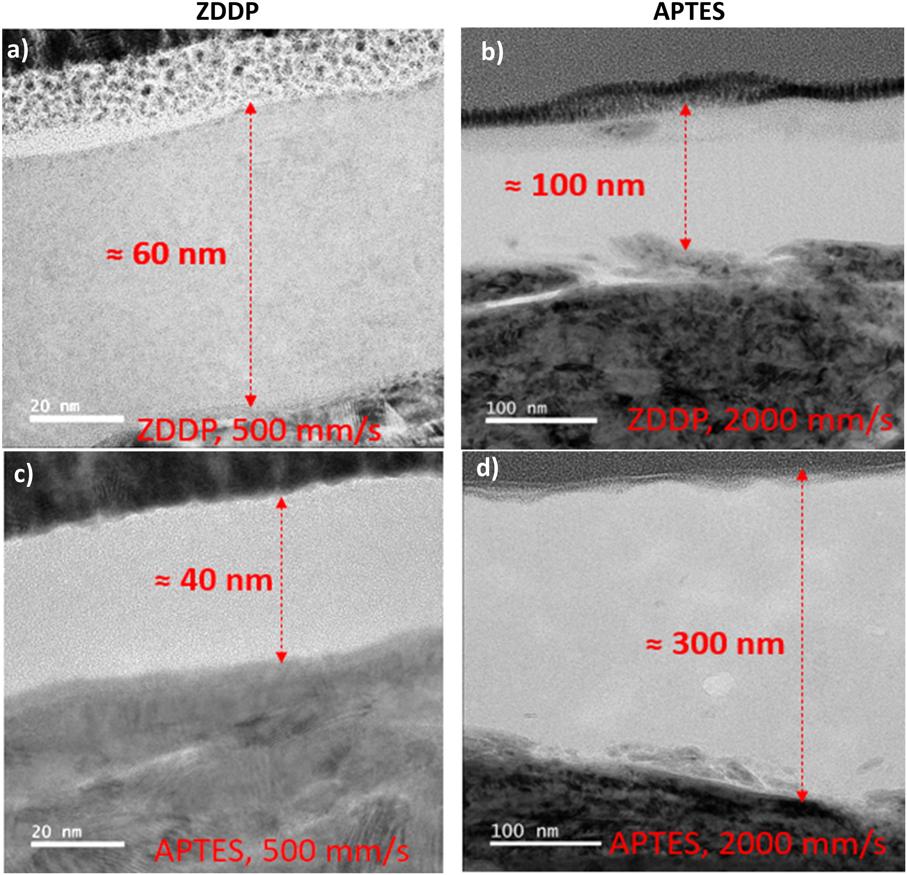
TEM-FIB cross-section of tribofilm manufactured on discs for the following samples (a) PAO + 10 wt% ZDDP, 500 rpm, (b) PAO + 10 wt% ZDDP, 2000 rpm, (c) PAO + 10 wt% APTES, 500 rpm, (d) PAO + 10 wt% APTES, 2000 rpm.
The proposed mechanism for manufacturing APTES tribofilm is illustrated in Figure 9. Before shearing surfaces, APTES self-assembled monolayer forms due to chemical interactions of ethoxysilane groups with the contact surfaces, resulting in a thin APTES monolayer (Figure 9). There is no strong chemical bonding or interaction between the APTES molecules (
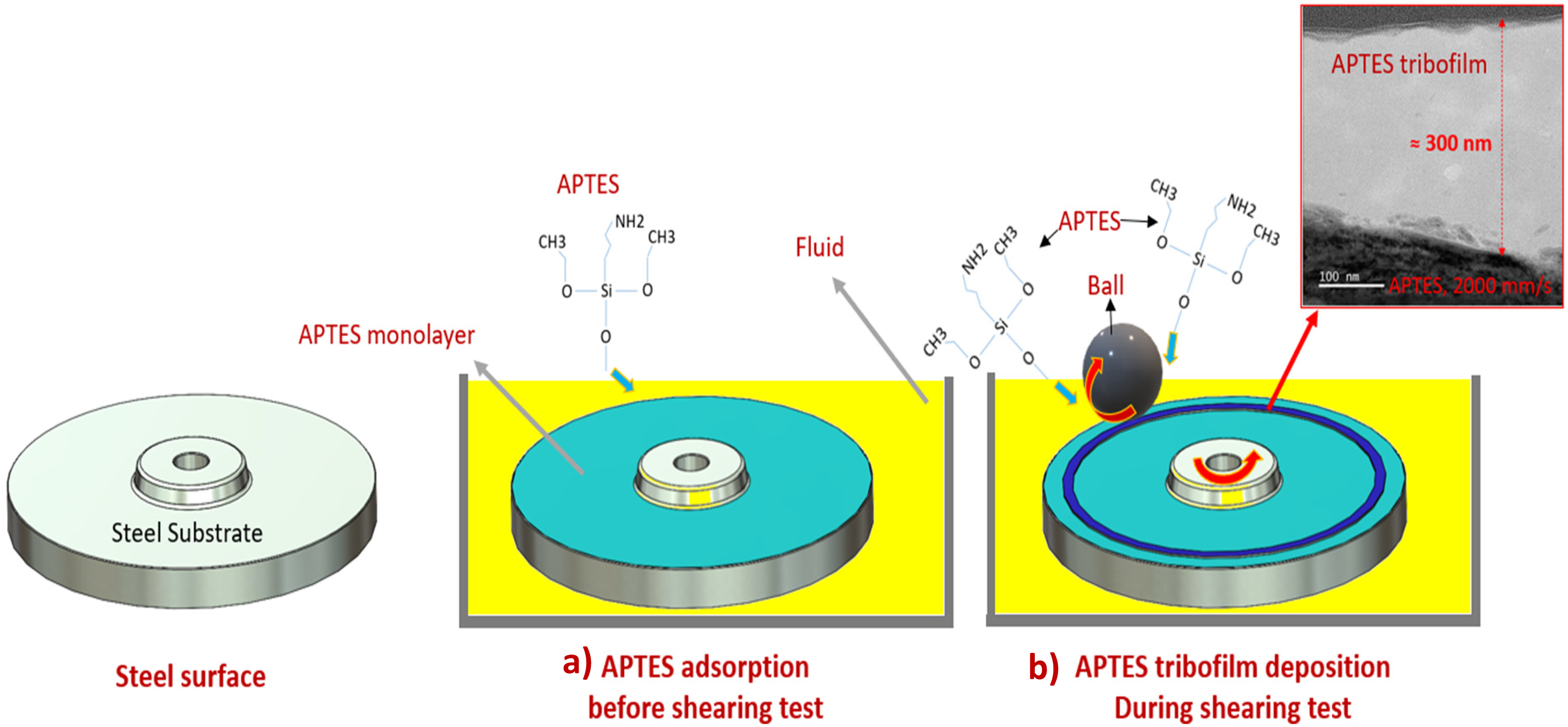
3D schematic explains the mechanism steps to manufacture the APTES tribofilm, (a) APTES molecules are adsorbed on the surface to form a monolayer, (b) APTES tribofilm is grown during the tribological test.
Tribofilm conductivity
The conductivity of ZDDP and APTES tribofilms has been carried out using AFM (C-AFM). The scanned area of disc samples in the wear track was 0.5*2 µm2. The topography and conductivity of ZDDP and APTES tribofilms are shown in Figure 10. The conductivity analysis was done by measuring the current flow through the AFM tip. The AFM measurements were taken along the manufactured films while avoiding uncovered areas by tribofilm.
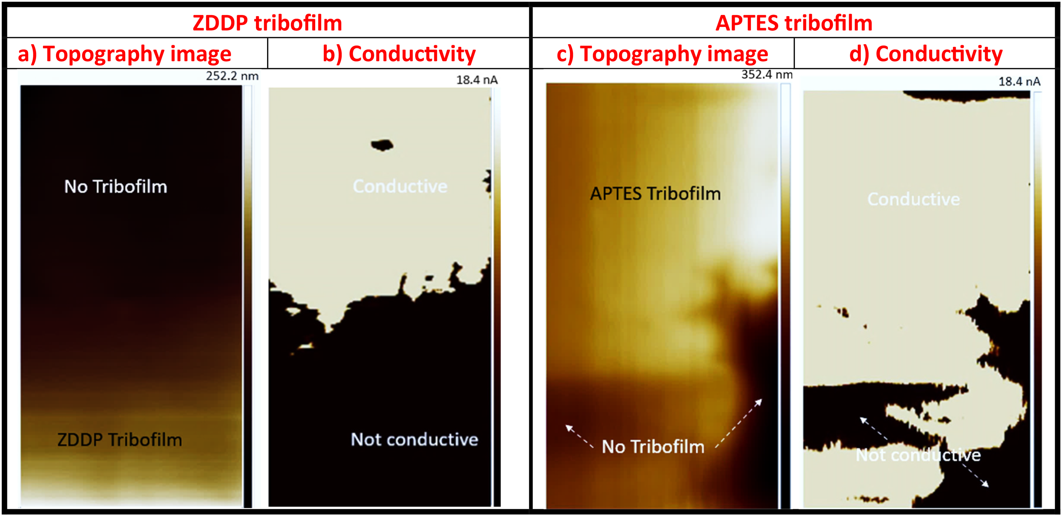
The topography and conductivity analysis for ZDDP and APTES tribofilms using C-AFM technique.
The topography of ZDDP tribofilm, as shown in Figure 10(a), demonstrates the existence of ZDDP tribofilm covering the halved image (bottom side). In Figure 10(b), the tribofilm is not conductive in the area that is covered by ZDDP tribofilm. The area covered by ZDDP tribofilm prevents the current pathway through the manufactured tribofilm. In the ZDDP topography (Figure 10(a)), where it is not covered by ZDDP tribofilm (top side), the current flows easily through the steel substrate. The results indicate that the ZDDP tribofilm is nonconductive. The results align with the previous study 8 that revealed the nonconductivity of ZDDP tribofilm. In Duston's study, the authors 8 combined ZDDP with a high concentration of graphene nanoparticles to form ZDDP film-rich carbon. The conductivity of ZDDP-rich carbon tribofilm was tested using the CAFM technique. The results indicated that the patches of current can access the surface. However, the author suggested that graphene distribution was a dominant factor that could affect the electrical conductivity of ZDDP/graphene film.
The topography and conductivity of APTES tribofilm are illustrated in Figure 10(c), (d). Figure 10(c) shows that APTES tribofilm covers most of the scanned surface. In parallel measurement, Figure 10(d) reveals that the current passes through the APTES tribofilm to the steel substrate. Some scanned areas, in Figure 10(d) where there is no APTES tribofilm, are nonconductive. This could be due to the formation of APTES film with different chemical compositions, which may affect the conductivity of the surface, preventing the current access through the steel substrate. Future work to explore in detail the APTES chemical composition and its correlation to the film conductivity is required.
The APTES tribofilm mainly consists of silicon/carbon-rich film, as demonstrated in Figure 7, which helps APTES film to be conductive compared to ZDDP tribofilm. 8 Yu et al. 37 used carbon nanotubes to manufacture a carbon-rich film using chemical vapor deposition (CVD). The carbon-rich film was found to be conductive film. 37 Similar chemical compositions of manufactured films in this study were found to be conductive and used in advanced wearable electronics. 38
Small sizes of electronics applications require low current carriers (lower than 0.01 nA) and high precision. 39 The current flow that was observed for the APTES film reached around 18 nA. This means the ability to use APTES as a functionalised film. In the present study, the limitation of measuring the APTES conductivity using C-AFM along the manufactured APTES film is that the current flows only through the film thickness. The presented results for current flow through the surface are in nanoscale and can be influenced by inconsistent contact between the AFM tip and tribofilm gradients, chemical composition of the film, and film thickness. 8
This new manufacturing method, using multiasperities sliding interfaces, allows the production of conductive and insulating layers on a flat substrate without damaging surfaces where the current can flow. This study contributes a step towards using tribology-enabled technology to manufacture electronics devices in the nano and microscale. Future work to manufacture APTES tribofilm with different soft substrates, such as silicon, is required.
Conclusions
In this study, manufacturing conductive tribofilms for potential MEMS/NEMS applications has been investigated using a new precursor material. Multi-asperity contact surfaces using the MTM tribometer were conducted. Two different precursor materials, including APTES and ZDDP as a reference, were used to manufacture tribofilms on steel surfaces. The main conclusions are:
3D tribofilm can be manufactured using the multi-asperity contact method without any wear or damage on the substrate, using parameters of mixed lubrication regime. Both precursor materials of ZDDP and APTES result in thick and robust tribofilms, under such specific tribology conditions. The rotation speed affected the formation of tribofilm for both precursor materials, significantly influencing the APTES tribofilm thickness. Based on the chemical analysis performed it was revealed that APTES tribofilm are rich with both silicon and carbon. The ZDDP nanostructured film is nonconductive compared to APTES conductive film.
Supplemental Material
sj-docx-1-pij-10.1177_13506501251349355 - Supplemental material for APTES nanofilm manufacturing using sliding interfaces
Supplemental material, sj-docx-1-pij-10.1177_13506501251349355 for APTES nanofilm manufacturing using sliding interfaces by Alaaeddin Al Sheikh Omar, Khurshid Ahmad, Ajay Pratap Singh Lodhi, Chun Wang, Krzysztof Kubiak and Ardian Morina in Proceedings of the Institution of Mechanical Engineers, Part J: Journal of Engineering Tribology
Footnotes
Acknowledgments
The authors acknowledge the support of the EPSRC project “Tribology as an Enabling Technology _TrEnt” with grant No. EP/S030476/1 for funding this work.
Declaration of conflicting interests
The authors declared no potential conflicts of interest with respect to the research, authorship, and/or publication of this article.
Declaration of data availability
The data are available when requested.
Funding
The authors disclosed receipt of the following financial support for the research, authorship, and/or publication of this article: This work was supported by the EPSRC (Tribology as an Enabling Technology _TrEnt), (grant number EP/S030476/1).
Supplemental material
Supplemental material for this article is available online.
References
Supplementary Material
Please find the following supplemental material available below.
For Open Access articles published under a Creative Commons License, all supplemental material carries the same license as the article it is associated with.
For non-Open Access articles published, all supplemental material carries a non-exclusive license, and permission requests for re-use of supplemental material or any part of supplemental material shall be sent directly to the copyright owner as specified in the copyright notice associated with the article.