
Abstract
This paper presents an experimental investigation into lift generation during the tangential motion of an inclined surface over a compressible porous layer, focusing on an exceptionally slow sliding speed, a condition that has not been considered in previous studies. Specifically, we validated Pascovici's one-dimensional lubrication model for an inclined slider under the above condition. Additionally, we explore the use of woven fibrous material for soft porous lubrication, broadening the range of media for future studies.
Introduction
This paper reports on an experimental investigation into the lift generation during the tangential motion of an inclined surface over a compressible porous layer. Herein, we focus on an exceptionally slow sliding speed, a condition that has not been considered in previous studies. The paper examines Pascovici's one-dimensional (1D) lubrication model 1 for an inclined slider under specific operating condition.
The basic concept behind soft porous mechanism is replacing the thin fluid film of traditional hydrodynamic lubrication with a porous layer saturated with fluid. This new lubrication mechanism relies on the reduced permeability within the pores under compression, leading to an increased resistance to fluid flow and consequently, a remarkable lift pressure generation. The pressure generated by this mechanism can exceed that of traditional hydrodynamic lubrication by 2–4 orders of magnitude.1,2 Theoretical models describing the lift generation effect of the regime were proposed during the 1990s and early 2000s by two independent research groups, those of Pascovici and Weinbaum. While these models were both derived from the famous Brinkman equation, which governs fluid flow through porous medium, they were developed for different working scenarios.1,2
On the one hand, in 2000, Feng and Weinbaum
2
published one of the most influential research papers in the field, which uses the square of a Brinkman parameter
On the other hand, the work of Pascovici et al. 6 on the topic can be traced back to 1994 when he patented a fluid pumping device based on a dislocation effect for Rayleigh's step slider. He later defined the mechanism with an abbreviation of XPHD, which stands for Ex-poro-hydrodynamic, in 2001. 7 Subsequently, the XPHD model was adapted for inclined slider and normal squeezing motion, opening a wide range of applications for the regime.1,8,9 It's important to highlight that most XPHD models can be solved analytically, seamlessly providing estimations of 1D pressure distribution. The XPHD model of the inclined slider has rarely been employed in any experimental studies, in contrast with the one by Feng and Weinbaum, thus opening a research gap for its validation.
While traditional hydrodynamic bearings face effectiveness limitations at lower sliding velocities, the soft porous mechanism theoretically offers a solution by providing greater lift. However, experimental proofs for low-speed sliding conditions have not been sufficient. This paper offers the solution to this issue via two experiments analysing permeability/porosity relationships and pressure generation in a linear slider test, tailored to validate the inclined XPHD model in slow tangential sliding. To elaborate, previous studies cover a velocity range of 1 to 3.8 m/s,3–5 while herein, we target a sliding velocity of only 0.06 m/s. According to our analysis, this velocity falls comfortably within the operational range of human joints. Existing literature also suggests that the mechanism not only works as a bearing but can also be an effective damper.8,9 Combining these factors, namely the potential multifunctional capability and the operational compatibility of the low-speed bearing within the human joint's range, the soft porous (XPHD) mechanism holds promising prospects for mimicking joint functions. Having a validated theoretical model would surely facilitate the development of such bearings.
Additionally, the paper explores the option of using a woven fibrous layer for lubrication purposes, which expands the media options for future papers concerning the topic.
Theory concepts
Porosity:
Porosity, denoted as
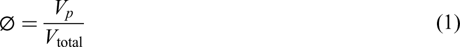
Porosity can be expressed as a percentage or as a value between 0 and 1, where 0 means entirely solid.
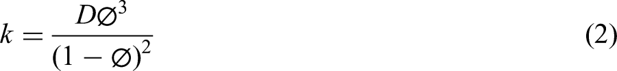
Permeability
Permeability, usually denoted as
Reynolds equation
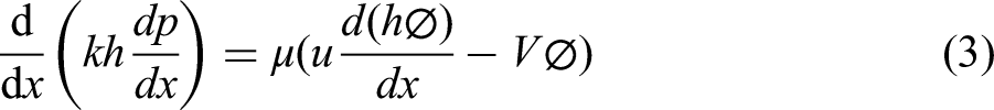
The pressure in porous media lubrication, generated on an inclined plane geometry was evaluated theoretically by Pascovici.
1
The pressure gradient along the length of the slider is given by the Reynolds equation:
Applying the Carman-Kozeny equation and the relationship between the layer's thickness and its porosity for inclined slider geometry, Pascovici
1
obtained his formula, which correlates the change of pressure corresponding to the change of porosity as follows:
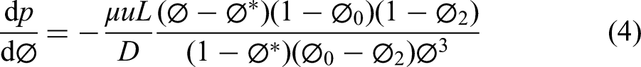
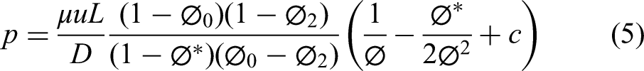
It is important to highlight that the pressure, p, denoted in Equation (5) is the pressure of the fluid phase. The pressurization of the fluid is the converging wedge mechanism. In the case of a porous layer, it is more difficult for the fluid to flow through the narrow spaces between the solid phase of the medium, therefore generating a much higher pressure and hence, a higher load capacity.
Experiments
Characterization of material
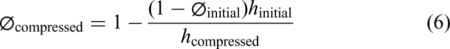
The porous material being used in this research is a woven polyester throw, with a relatively smooth surface and has an average thickness of 3.66 mm. By using the weight measurement technique as detailed in Kunik et al., 10 the average initial porosity of the material was found to be 0.976, which means the material consists of 97.6% pores.
The porosity at the corresponding compression rate is calculated using the formula:
In contrast with other papers that aim defining permeability-porosity for fibrous material,3,11,12 the average fibre diameter was not measured herein; the parameter along with dimensionless constant
Permeability test
Permeameter setup
The aim of this experiment is to determine the complexity constant D of the porous layer, a crucial parameter in completing the Carman-Kozeny equation, required for lift generation estimation.
The permeameter used in this study resembles the design employed by Lundstrӧm et al. 13 for investigating unidirectional permeability. This design has been adapted with improvements as proposed by Turtoi et al. 11 and Kunik et al. 10 The permeability is achieved by measuring water output velocities corresponding to anticipated pressure gradients that caused the flow.
Figure 1 shows the primary structure of the permeameter, consisting of an acrylic chamber open at one end. In the base of this chamber, a rectangular cavity of 300 × 100 × 10 mm was machined, housing the porous layer. Positioned near the closed end, along the centre line of the pocket, three 1/8-inch BSP holes were drilled. Each of these hole serves a distinct purpose: one for connecting a pressure transducer, the second for flow inlet and the last one for releasing any excess pressure. The pressure transducer used herein is a Honeywell ABP series pressure sensor with maximum capacity of 34.5 kPa (5 psi) and has an error band of 1.5%. Strategically placed next to the porous medium, opposing the flow direction, it ensures accurate measurement of flow's pressure before reaching the layer.
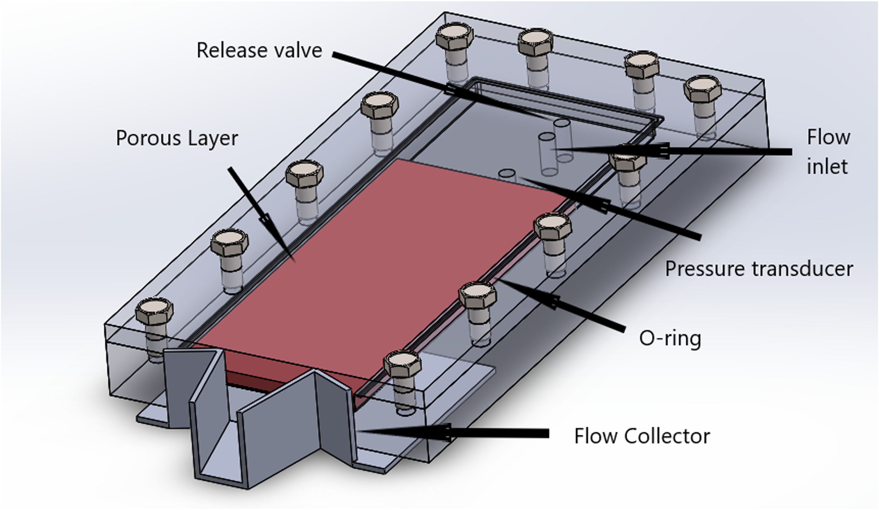
Permeameter setup.
To anticipate the flowrate of water inlet, a miniature pump was employed. In addition, a release valve, attached to the last hole, stabilizes the pressure during the test and bleeds air out from the pocket. The varying thicknesses of the top-shaped plates enclosing the chamber determine the compression rate of the porous layer. The assortment of these lid plates compresses the porous layer at a range of 3.15–1.61 mm. The enclosed permeameter was sealed by fitting an O-ring into a groove, machined next to the closed edges of the pocket.
As suggested by Kunik et al., 10 the sample size was chosen slightly wider than the width of the pocket to avoid the edge effect. A rectangular sample was cut from the polyester sheet with dimensions of LxB = 250 × 110 mm. The uncompressed thickness of this specimen is the same as the ones used in the characterization step, which is 3.66 mm. A simple bulk flow collector is also used to eliminate the side effect. This collector gathers flow from the central 50 mm region at the open end of the chamber while diverting all side flow.
The experimental procedure initiates with a 15-min warm-up period, during which water is circulated through the sample at a constant pressure of 30 kPa. This preparation step is essential for ensuring the complete water saturation of the sample. Following this, once the pressure is adjusted to the desired level, the flow rate is attained by weighing the amount of water passing through the bulk collector during a fixed duration. Each measurement is taken three times and average values are recorded. In addition, pressure data are collected at 10-s intervals and averaged. The chosen pressure range, being presented in the next section, is a result of iterative testing to achieve an optimized range that is limited by the pump's power and sensor's capacity.
Interpretation of results
Permeability corresponding to different porosity levels can be determined from pressure gradients and flow velocities. For this purpose, two models governing fluid flow through the mediums are utilized and their suitability with the specified testing conditions is compared herein. The first one, the oldest and most well-known model, is Darcy's law. It details that the pressure gradient across a unit length of porous medium is linearly proportional to flow velocity and fluid's dynamic viscosity while at the same time, is inversely proportional to the permeability of the porous material.
11

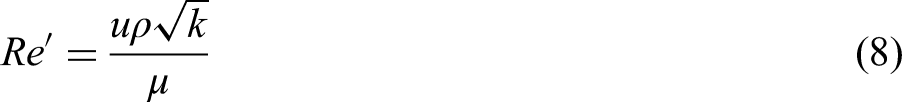
It is worth noting that Darcy's work was derived for laminar flow only and thus checking the flow condition would be necessary before applying it. Hence, a permeability-adapted version of Reynolds number is used:
Darcy's law can be modified by introducing an inertia term (drag force), which would explain the non-linear trend of the flowrate against the drop of pressure. The method, so-called Dupuit-Forchheimer has been proven to provide a better fit to experimental results compared to Darcy's model for non-Darcian, higher velocity flow.10,11 In this case Darcy's equation becomes:
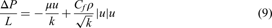
Divide both sides for u, we have:
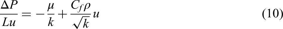
Figure 2 shows the maximum permeability adapted Reynolds number corresponding to each porosity (compression) level. As pointed out, all the tests were carried out under the laminar flow condition of
P/L versus flow velocity.
Permeability versus porosity with curve-fitting.
Both the traditional model and the Forchheimer corrected one provided similar results, as per Figure 4. The difference between the two interpretations was marginal, indicating the inconsequential effect of the drag forces to the fluid passage, under laminar, low-pressure flow conditions. The Carman-Kozeny relationship is then curve fitted to find the value of the empirical constant D which represents the structural characteristic of the chosen material as seen plotted as the solid line (Figure 3). In this case, D was found to be
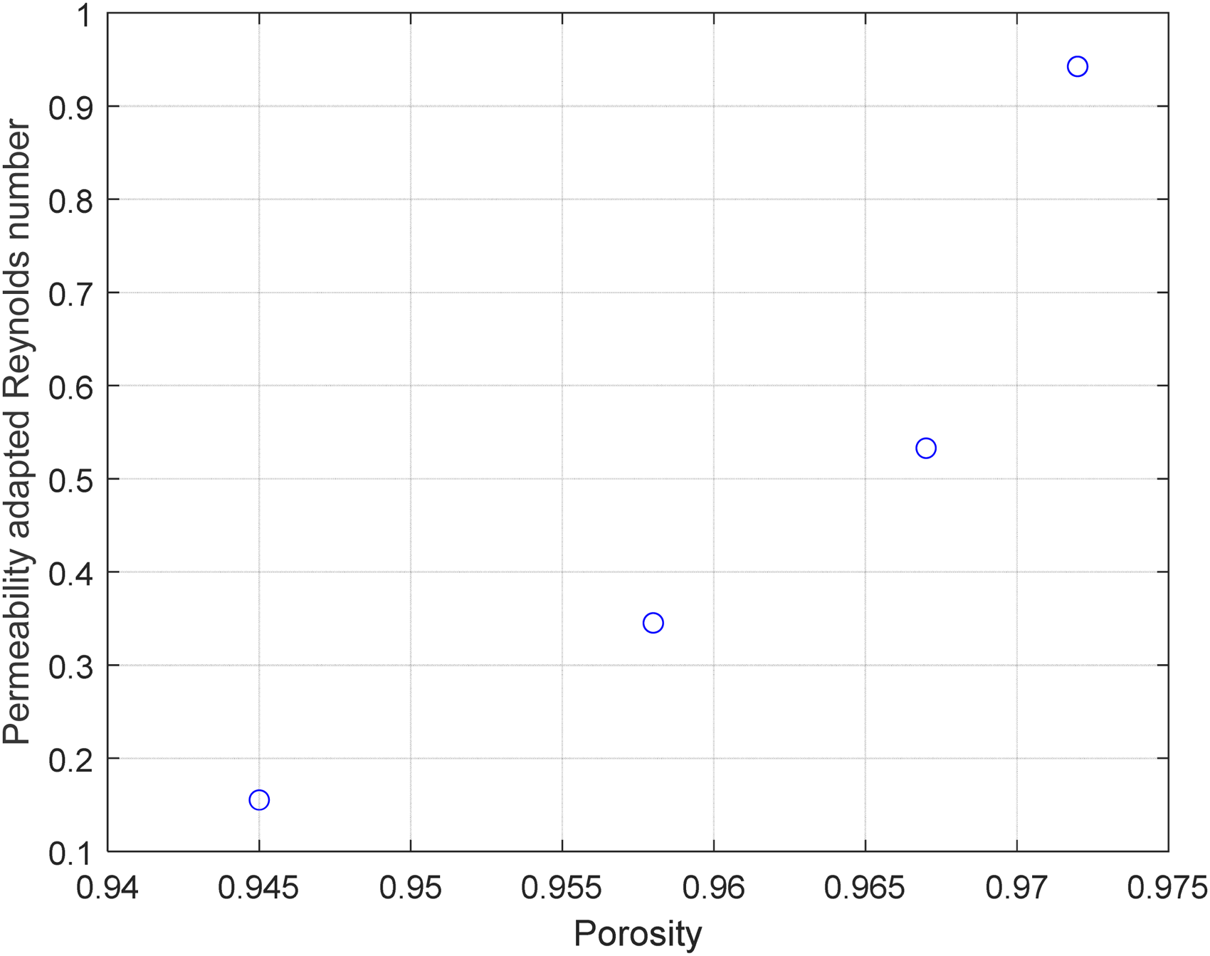
Reynolds number versus porosity levels.
Lift generation test
Experimental setup
In order to validate the XPHD model, an in-house developed linear slider setup was utilized, featuring unique design elements, tailored for specific conditions. Capillary tubes were integrated to monitor pressure beneath the pads, allowing pressure distribution at mid-plane to be observed directly. Figure 5 illustrates a schematic of the design, while Figure 6 captures the actual setup.
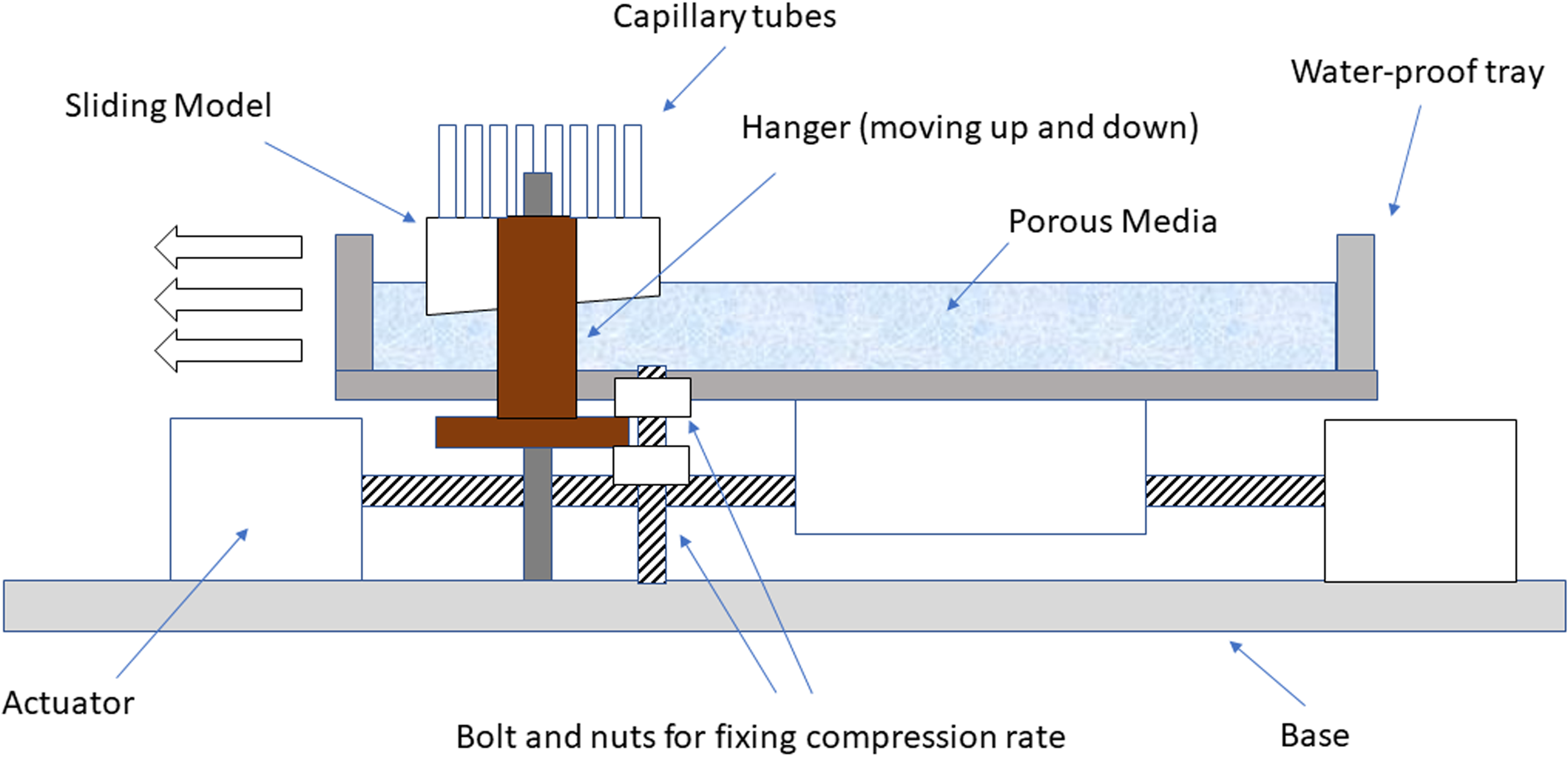
Schematic of the lift generation test.
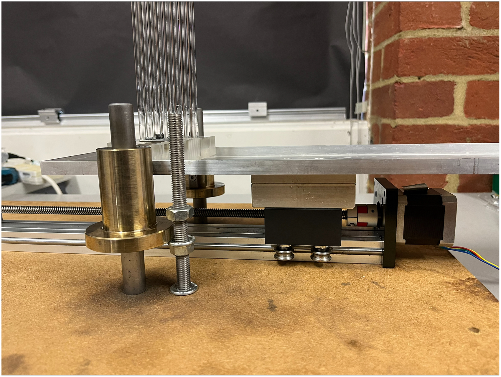
Picture of lift generation setup.
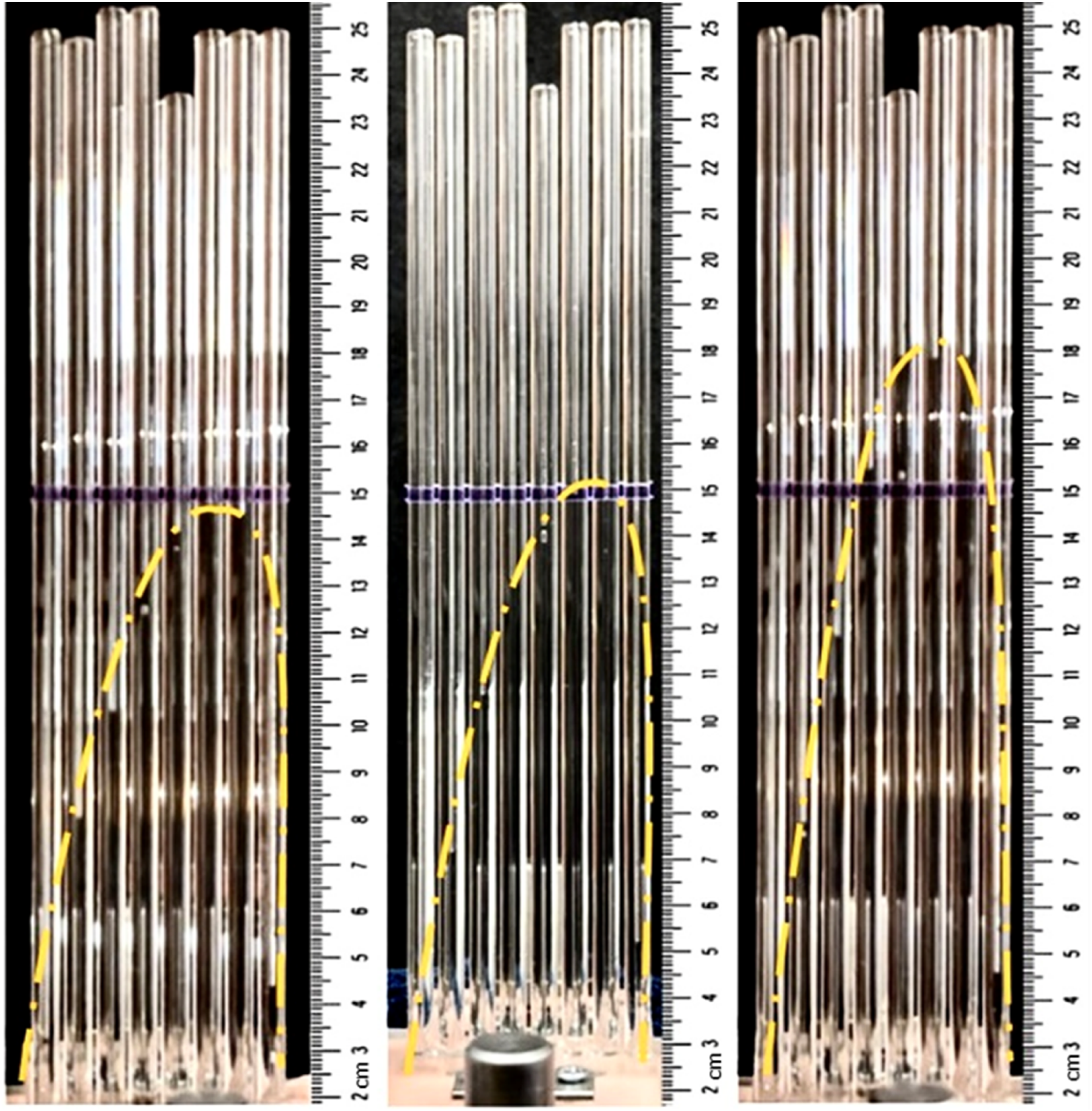
Examples of lift generation display for different levels of solid surface separation (from left to right: 1.54, 1.45, 1.28 mm).
Previous studies using linear sliders to investigate soft porous lubrication models focused on air pressure generation at higher speeds, akin to skiing and tobogganing motions rather than the slower movements typical of animal joints, which are imbibed in synovial fluids.3–5 Literature review shows a lack of research supporting functional soft porous lubrication with liquid lubricants and slow tangential motions, which can be relatable to animals’ joints. Taking human's shoulder for example, the humeral head has a mean radius of curvature of 22.9 mm 15 and an angular velocity of 15 rad/s 16 which is equivalent to a sliding velocity of only around 0.3 m/s – a value three times smaller than the existing minimum. Moreover, in the absence of disease, the joint can operate smoothly under heavy loads at significantly slower speeds. Therefore, a specific sliding velocity of 0.06 m/s was chosen to assess the XPHD model, as it would be comfortably within the natural operating range of joints.
The test rig consists of four main components: a watertight tray to hold the medium, an actuator to pull the tray, sliders, and a hanging structure to support the sliders. The tray being 390 mm long and 114 mm wide, was rigidly attached to the actuator's runner. The actuator was driven by a stepper motor using a lead screw with the total length of 380 mm. As the motor turns, the runner carries the porous tray, and slides underneath the pads.
Two sliding pads with respective width-to-length ratios (0.87 and 2.00) were utilized to evaluate the side leakage effects. Both pads share a profile length of 55 mm and a fixed inclination angle of 2.08°, featuring series of holes mid-plane to accommodate the capillaries tubes and allow fluid passage. This assortment of inclined pads and tubes sat atop the medium tray with support from the hanging structure, which can be vertically adjusted to alter the compression level. The compression can also be fixed by using a bolt and double nuts mechanism which can be seen in Figure 5.
The experiment preparation commences with cutting the porous medium to fit the tray, attaching them together, then soaked in water for one day to ensure full imbibition. At the start of the experiment, the pad and tubes assortment were fixed at the desired height. Subsequently, as the porous layer is pulled underneath the pad, the pressure distribution is observed via the transparent capillary tubes.
Experimental results
To examine the validity of the theoretical model, a series of experiments were conducted, the results being presented in this section.
The compressed thickness at the trailing edge of the bearing is first set as 1.45 mm
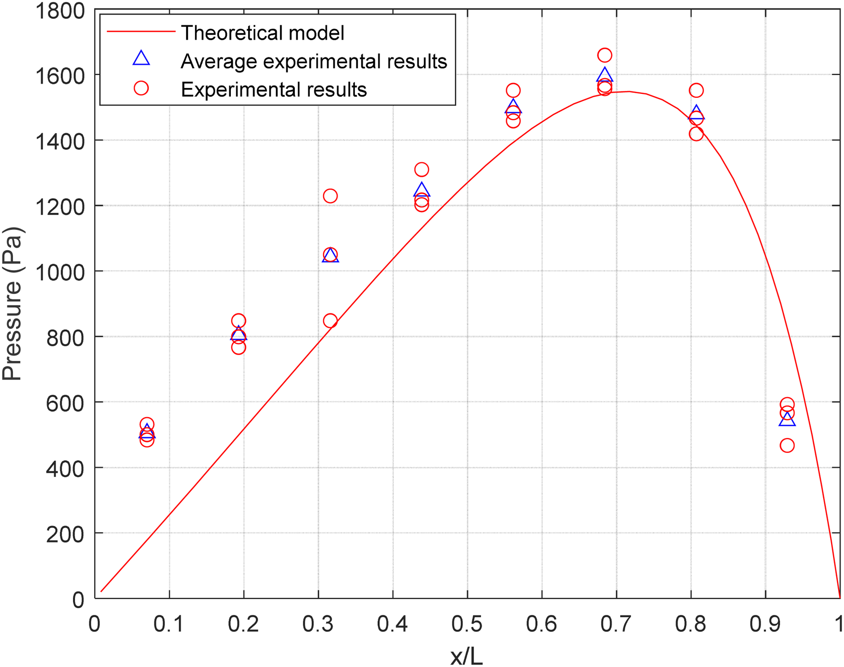
Pressure distribution for one-dimensional (1D) inclined sliding model at 1.45 mm lowest layer thickness.
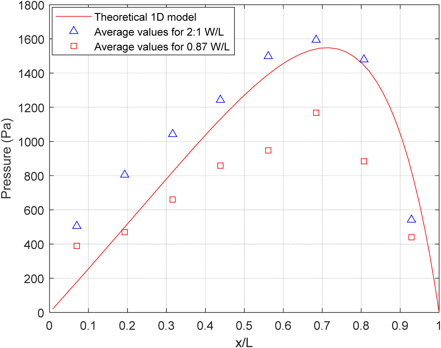
Effect of side leakage comparison at 1.45 mm lowest layer thickness.
For 2:1 W/L pads, the experimental data agrees well with Pascovici's model, 1 with the difference between the maximum pressure magnitudes of theory and experiment being only 6%, and its location predicted precisely. As shown in Figure 8, the pressure starts low at about 500 Pa, peaks around 1500 Pa towards the end, then reduces sharply. The shape of the distribution is similar to the experimental findings for the 1D planar board of Gacka et al., 3 and Zhu et al., 4 with pressure reaching a maximum at x/L between 0.6 and 0.8. The values measured here are several times larger than the ones obtained in those studies due to differences in testing conditions. For example, air was used in their study as a lubricant, which has a much lower viscosity compared to water. Since lift generation is due to the resistance of fluid flow, the higher the viscosity, the higher the pressure. This effect was studied in, 10 showing an oil-lubricated thrust bearing can generate up to 10 times the pressure a water-bearing did using the same test bench.
A parametric study was also carried out using this wider pad, examining the lift at multiple compression levels,
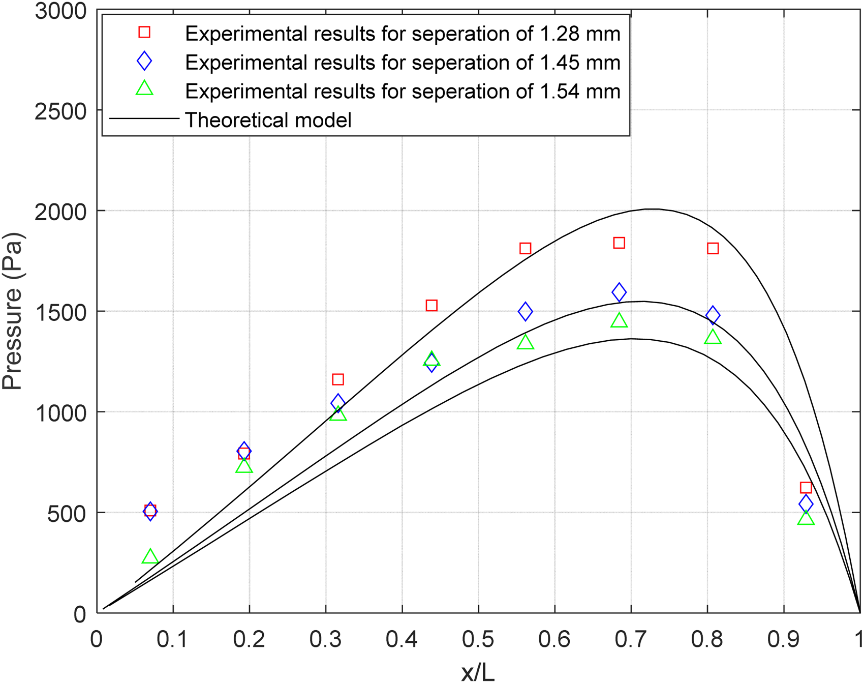
Pressure distribution for one-dimensional (1D) inclined gliding model at different compression levels.
The second sliding pad, which allows side-pressure leakage, shows a significant difference. The pressure still begins at a low level but increases much more slowly, with the maximum pressure only reaching 1200 Pas, 20% lower than the theoretical 1D model. The effect of side leakage is clear as all data points are visibly lower than those obtained with wider bearings. According to the literature review, a 2D bearing with a W/L ratio of 0.182 can generate pressure as low as 10% of that produced by an infinitely long bearing. 16
A consistent pattern noted throughout all the tests was that the pressure field near the leading edges of both gliding pads was higher than predicted. This can be seen in Figure 8, where the measured values for the third fluid columns varied widely compared to the rest. The authors believe that these irregularities were caused by the initial compression at the start of each test. As the gliding pad lowered to the desired thickness, it squeezed the biphasic layer normally, resulting in fluid penetration in each capillary prior to the test. The levels of fluid due to this process, a so-called squeezing motion, were not equal among the tubes. It was observed that this squeezing pressurization did not persist and often dropped immediately following the squeeze. However, in some tubes, the fluid did not fully escape, leaving a discontinued body of fluid hanging inside. Subsequently, during tangential motion, if the generated pressure could result in a column tall enough, it could connect the trapped fluid and continue to rise under the effect of sliding lift. On the other hand, if the pressure is not sufficient, the isolated fluid body would be maintained at that level.
In general, despite encountering errors at the forefront of the pads, likely due to the limitations of the equipment, Pascovici's 1D model successfully predicted the pressure distribution for inclined sliding bearings under the mentioned low-speed operating conditions. The results demonstrate the applicability of the XPHD model in settings similar to those found in natural joints. The validated theoretical model can subsequently be adjusted for various geometries, making it easier to develop XPHD-based bearings, particularly those intended to replicate the functions of natural joints.
Conclusions
This paper reports an experimental investigation into the validity of the soft porous lubrication (XPHD) theory for linear inclined slider, focusing for slow-speed, water-imbibed scenario. The research consisted of two experiments: One studied the permeability of the material while the other looked at the pressure distribution along the sliding surfaces.
During the permeability test, it was observed that under the laminar low-velocity condition, the relationship between the pressure gradient across the length of the porous layer and resultant flow rate can be approximated as linear. Thus, Darcy's law was considered valid and employed to interpret the measured data, providing the permeability against porosity graph. The interpretation was also compared to the Forchheimer corrected model, showing a similar result with less than 10% difference. This agrees well with other studies,10,11 which state the validity of Darcy's law for laminar flow but at a much higher flow velocity. By combining the fibre diameter and the complexity constant in the Carman-Kozeny equation, a single effective characteristic constant was derived from the experimental data. This allows the permeability-porosity correlation of non-uniform porous material to be estimated; in this case, a woven porous material was used.
The findings above were then applied to Pascovici's analytical model of 1D inclined bearing to predict the pressure distribution. The results of the second experiment justified these predictions with measured pressure values using a custom linear slider setup. The unique aspect of the test rig presented here lies in its focus on an exceptionally slow sliding speed of 0.06 m/s, which corresponds to the movement typically found in natural joints. Furthermore, the low-velocity operating condition has always posed a challenge for hydrodynamic bearings. The poroelastic regime, known for achieving outstanding lift, may offer a solution to this limitation. The theoretical model validated in this paper can subsequently be adapted for different geometries, facilitating the development of XPHD-based bearings, especially, those designed to mimic the functions of natural joints.
Footnotes
Acknowledgements
The authors extend gratitude to Professor Rupert Young, Mr Jack Moss, and Ms. Amelia Nguyen for their invaluable editorial assistance, as well as the unwavering support provided by the professional service staff at the University of Sussex, without whom this paper would not have been possible.
Declaration of conflicting interests
The authors declared no potential conflicts of interest with respect to the research, authorship, and/or publication of this article.
Funding
The authors received no financial support for the research, authorship, and/or publication of this article.