
Abstract
The low service performance and sudden failure characteristics of coated self-lubricating spherical plain bearings (SPBs) limit their engineering application prospects. In the current study, two new self-lubricating coatings types were applied to the bearing contact surfaces. The bearings were compared and investigated using life tests. Furthermore, the wear failure mechanism was investigated. The results show that self-lubricating coatings improved the service performance of the traditional bearings with manganese phosphate coating. Among them, double-sided coated bearings had the best service performance and life. More interestingly, the torque and temperature rise signal curves will show a notable signal downstage before the signal mutation stage. The large-area and complete mixed friction transfer film on the contact surfaces was the main reason for the signal downstage. Moreover, the failure mechanism changed from abrasive wear to adhesive wear and fatigue wear with the increment of load. This study results preliminarily verify the performance improvement of high-performance coatings and provide a theoretical reference for further breaking through the engineering application bottleneck of coated self-lubricating SPBs.
Keywords
Introduction
The performance of space motion mechanisms is becoming more and more significant with the vigorous development of space technology. Some precision friction parts determine their service reliability, such as many types of bearings, gears, and so on.1–3 Among them, self-lubricating spherical plain bearings (SPBs) are indispensable parts, which include a spherical inner ring, outer ring, and a lubricating layer.4,5 As we all know, the state of the bearing contact surfaces decreases with the wear of the lubricating layer. The bearing clearance continues to increase, thus greatly reducing the operating accuracy. A bearing failure seriously affects the service reliability of space-moving mechanisms.6,7 However, the harsh space environment limits the application of traditional oil/grease lubrication technology. Advanced coating technology can cope well with a variety of extreme space environmental factors.8–13 In recent years, researchers have applied solid lubricating materials (such as carbon-based materials, layered compounds, etc.) to the surfaces of bearings to improve their service performance.14–16 Coated self-lubricating SPBs have a great application prospect in the aerospace field. However, to the best of our knowledge, most studies have predominantly been conducted on self-lubricating coatings. The results on the failure mechanism of coated SPBs are few.
At present, fiber fabric liners are the most mature lubricating layer material used in SPBs. 17 Qiu et al.,18,19 Qi et al., 20 and Cui et al. 21 studied the service performance of polytetrafluoroethylene (PTFE) gasketed-type SPBs and revealed their wear failure mechanism. Their results suggested that a complete PTFE transfer film under heavy-load and high-frequency working conditions ensured bearings’ long-term stable running. 18 The wear consumption and extrusion of PTFE fibers were the main cause of the decline in the bearing performance. 20 The macro wear loss caused by lubricating liner gradual wear showed a relatively linear increasing law. As a result, failure of gasketed-type bearings could be prevented in advance by setting a maximum wear threshold. 19
The diversity of self-lubricating coatings leads to great differences in the failure mechanism of coated SPBs. In our group's preliminary studies,22,23 a general method for determining the failure of coated bearings based on torque and temperature rise signals was established. Different from gasketed-type bearings, the signal change law had a sudden change when the coated bearing failed. More specifically, the sudden change in torque and temperature rise signals caused by friction pair transformation and matrix wear indicated bearing failure. 23 Therefore, it was almost impossible to predict the bearing failure due to the sudden change of signals, which limited the application prospects of coated SPBs.
To break through this bottleneck, it is possible to find a solution from the self-lubricating layer materials. Molybdenum disulfide (MoS2) and diamond-like carbon (DLC) are well-known solid lubricating materials that have excellent tribological properties.24–33 MoS2 coatings can quickly form a lubricating transfer film due to its two-dimensional layered structure.34–36 However, the coating will fail rapidly under high loads caused by its low load-bearing capacity.37–39 In Qiu et al., 40 a composite coating consisting of MoS2 and graphite doped was applied to the surfaces of the SPBs. The results suggested that the service performance of the bearing has been slightly improved. However, there was no complete transfer film on the bearing surfaces. The sudden failure could not be solved. In the latest study, Zhang et al.41,42 combined the advantages of MoS2 and amorphous hydrogenated carbon (a-C:H) to develop a bilayer a-C:H/MoS2 coating. a-C:H greatly improved the load-bearing and adhesion of MoS2. Moreover, the layered structure of MoS2 promoted the formation of a graphene transfer film. A super-lubricity system occurred (friction coefficient was less than 0.01). These studies provide some inspiration for how to improve the tribological performance and predict faults of the SPBs. In recent years, there are no studies on the application of high-performance coatings to the surfaces of actual SPBs.
In this work, a high-performance a-C:H/MoS2 coating was applied as a lubricating layer to the spherical surface of the inner ring, and the a-C:H coating was applied to the outer ring surface of the SPBs. A new coated self-lubricating SPB (type GE17E/HEK) was developed. Subsequently, the service performance of bearings with different coating types under different loads was compared based on the bearing life tester. The wear failure and mechanism were comprehensively investigated. The aim of this study is to provide some new inspiration and theoretical reference for investigating the failure behavior and function customization design of new-type coated bearings.
Experiments
Bearing samples preparation
GE17E/HEK bearings were jointly developed by three research institutes. Specifically, the bearing design scheme was provided by Ma's group. Fujian Longxi Bearing (Group) Corp., Ltd, China provided the semi-finished bearings and carried out the later assembly work. The spherical surfaces of the SPBs were coated by Zhang's group at the Lanzhou Institute of Chemical Physics.
All static indexes of GE17E/HEK bearings met the standards after inspection by Fujian Longxi Bearing (Group) Corp., Ltd Some indexes could refer to the GJB 5502—2005 standard. Bearings were produced in the same batch. Figure 1 shows the appearance and structure of GE17E/HEK bearings.
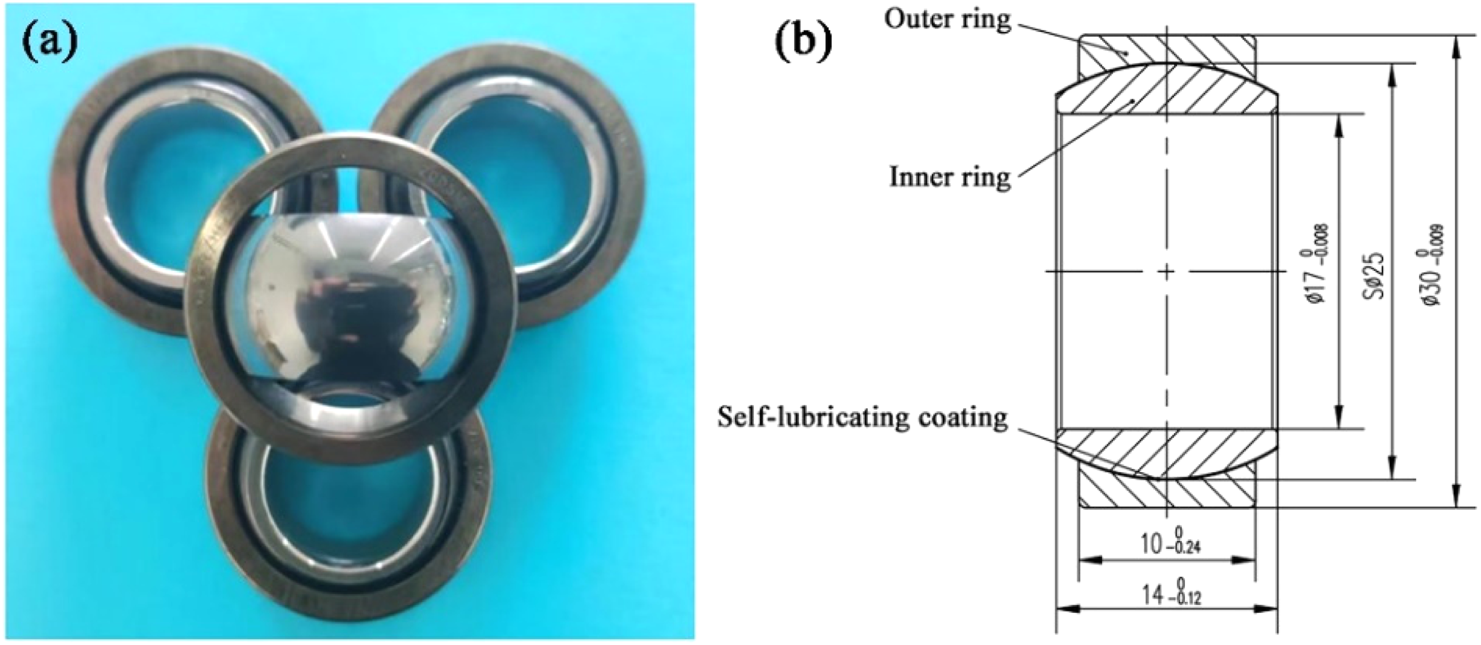
GE17E/HEK bearings: (a) Appearance; (b) Basic structure.
The bearing substrate material was GCr15, and the average hardness was not less than 50 HRC. Bearings in the article were divided into three types according to the different coating types. Bearings with both inner and outer ring surfaces coated were Type-1. Bearings with only the inner ring coated were Type-2. Bearings with only the outer ring coated were Type-3. The details are provided in Table 1.
Types of the series of GE17E/HEK SPBs.
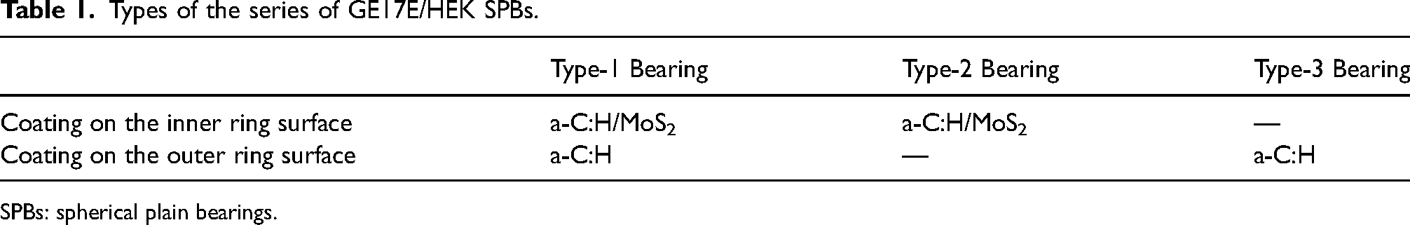
SPBs: spherical plain bearings.
Information about the coating could be obtained from previous work.42,43 Both a-C:H coating and MoS2 coating show a typical dense columnar structure. As shown in Figure 2, two coating types were successfully deposited on the spherical surfaces of the SPBs. The lubricating layer on the outer spherical surface of the inner ring was a-C:H/MoS2 coating with an average thickness of approximately 2.3 ± 0.3 μm. The preparation method was high-power impulsed magnetron sputtering (HiPIMS). 42 As shown in Figure 2(a), the coating surface was generally flat, but some slight damage was exhibited. In Figure 2(c), Raman peaks within 350 cm−1 to 450 cm−1 corresponded to the typical E12g and A1g modes of MoS2. Besides, the typical Raman peaks of a-C: H film appeared in the range of 1200 cm−1∼1800 cm−1.
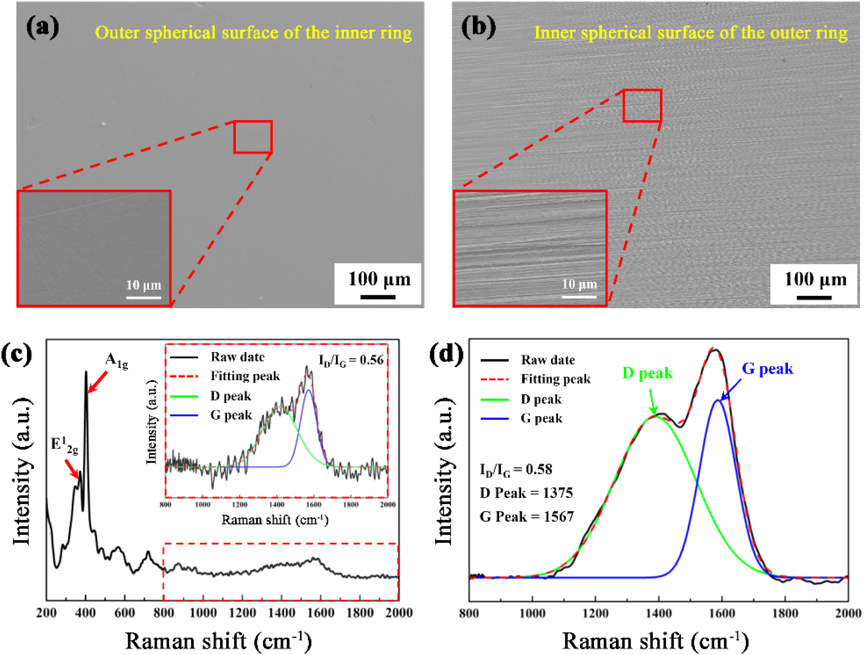
Initial surface morphological characteristics of the spherical surfaces of GE17E/HEK SPBs: (a) SEM images of the inner ring surface, and (b) outer ring surface; (c) Raman spectra of inner ring coating (a-C:H/MoS2), and (d) outer ring coating (a-C:H).
The lubricating layer on the inner spherical surface of the outer ring was a-C:H coating with an average thickness of approximately 1 ± 0.3 μm. It was also prepared by HiPIMS. 43 As shown in Figure 2(b), many regular scratches were distributed on the coating surface, which originated from the processing of the bearing. It was hard to carry out good surface polishing due to the structure of the inner spherical surface. Raman spectra indicated that a-C:H coating was successfully deposited on the outer ring surface (in Figure 2(d)).
Bearing life testing
The service performance of the bearings was tested using a wear life tester for SPBs (in Figure 3). The tester was composed of the transmission system, loading system, measurement system and fixture parts. The transmission system was composed of a swing hydraulic cylinder, a transmission spindle, and a bellows coupling. The tester could simulate the axial swivel of the bearing. A weight device was used as the loading system to provide constant radial load. The maximum load was 1000 N. The measurement system was composed of a high-precision torque sensor and thermocouple temperature sensor, which could monitor the friction torque and temperature of bearings in real-time. The torque sensor was connected to the spindle through a coupling, and the maximum friction torque was collected every 100 swing cycles. It was important to emphasize that the temperature sensor could only touch the surface of the outer ring (approximately 2.5 mm from the friction surface) due to the fixture structure. The friction temperature could only be used to assist in characterization. A special fixture for bearings in light-load, low-frequency conditions was composed of a loading plate, clamping piece, and accompanying rolling bearing. The left and right end faces of the outer ring of the bearing and the end face of the loading plate were clamped by clamping pieces to prevent the outer ring and the inner hole of the loading plate from slipping. The two end faces of the inner ring were clamped by the accompanying rolling bearing and the lock nut to prevent the inner ring and the core shaft from slipping. Sensor calibration work was carried out by a professional organization to ensure the accuracy of the signals before the tests. The torque and temperature signals were recorded and formed curves by a computer to ensure that the testers judged the running state of the bearings in time.
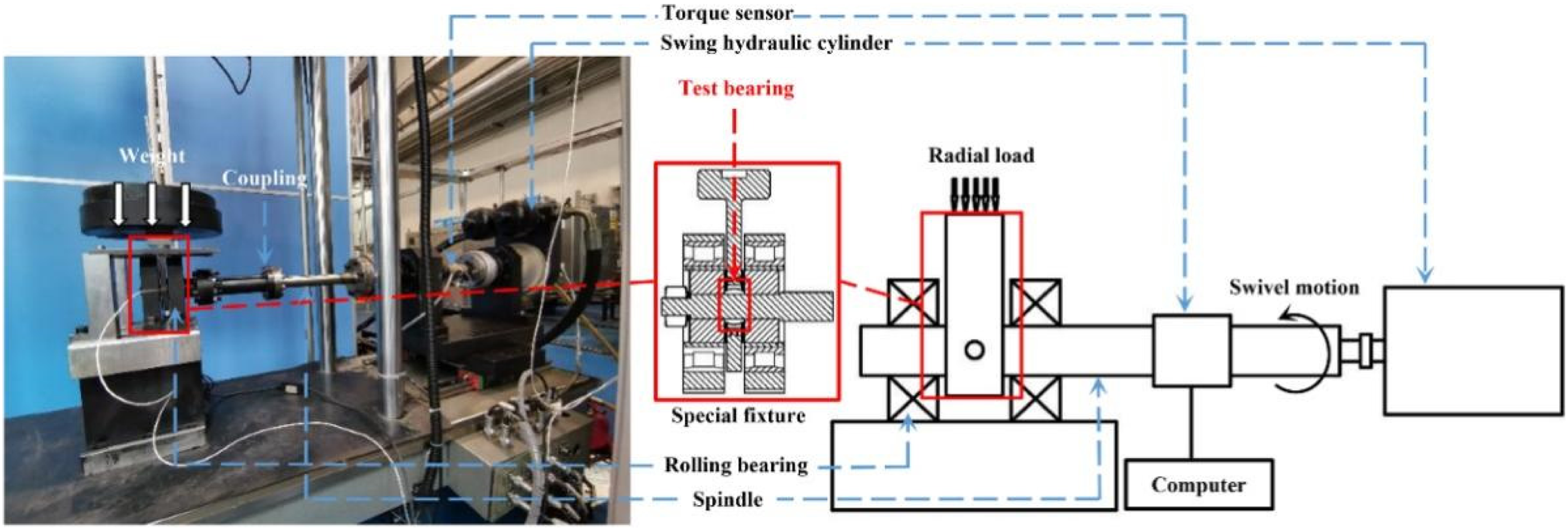
Life tester for the SPBs. 22
All tests were conducted in atmospheric conditions. The axial swivel motion angle of the bearing was ±10°. Because the bearings in the space motion parts work under a preload. Their motion mode is usually low-speed or intermittent motion. Combined with the previous work, light-load and low-frequency conditions were selected. Load had a more significant effect on the bearing. 22 Therefore, the radial loads applied to SPBs were 100 N, 200 N, 300 N, and 500 N respectively. The swivel frequency was maintained at 2 Hz. Moreover, the performance and life of Type-2 and Type-3 bearings were investigated at 100 N and 200 N. At least three repeated tests were carried out under each load condition. The criterion for bearing failure was set as follows: when the frictional torque and temperature signals changed suddenly and the torque value increased to 1.5–2.0 times of the average torque value of the steady state.
Characterization of the worn bearings
Bearing samples were cut using a wire-cutting machine after the life test. The samples were ultrasonically cleaned in anhydrous ethanol for approximately 15 min to remove oil and impurities. The surface morphologies of the SPBs were observed via an environmental scanning electron microscope (SEM, ZEISS, SUPRA55, Germany). Furthermore, the bonding structures of the self-lubricating coatings were examined via a Raman spectrometer (Horiba scientific, LabRAM HR evolution, Japan) with an excitation wavelength of 532 nm. The test range was 100∼3 000 cm−1. Finally, the element distribution in the typical wear zones was investigated via X-ray energy spectrometer (EDS, Oxford, Inca act, England).
Results and discussion
Service performance of Type-1 bearings
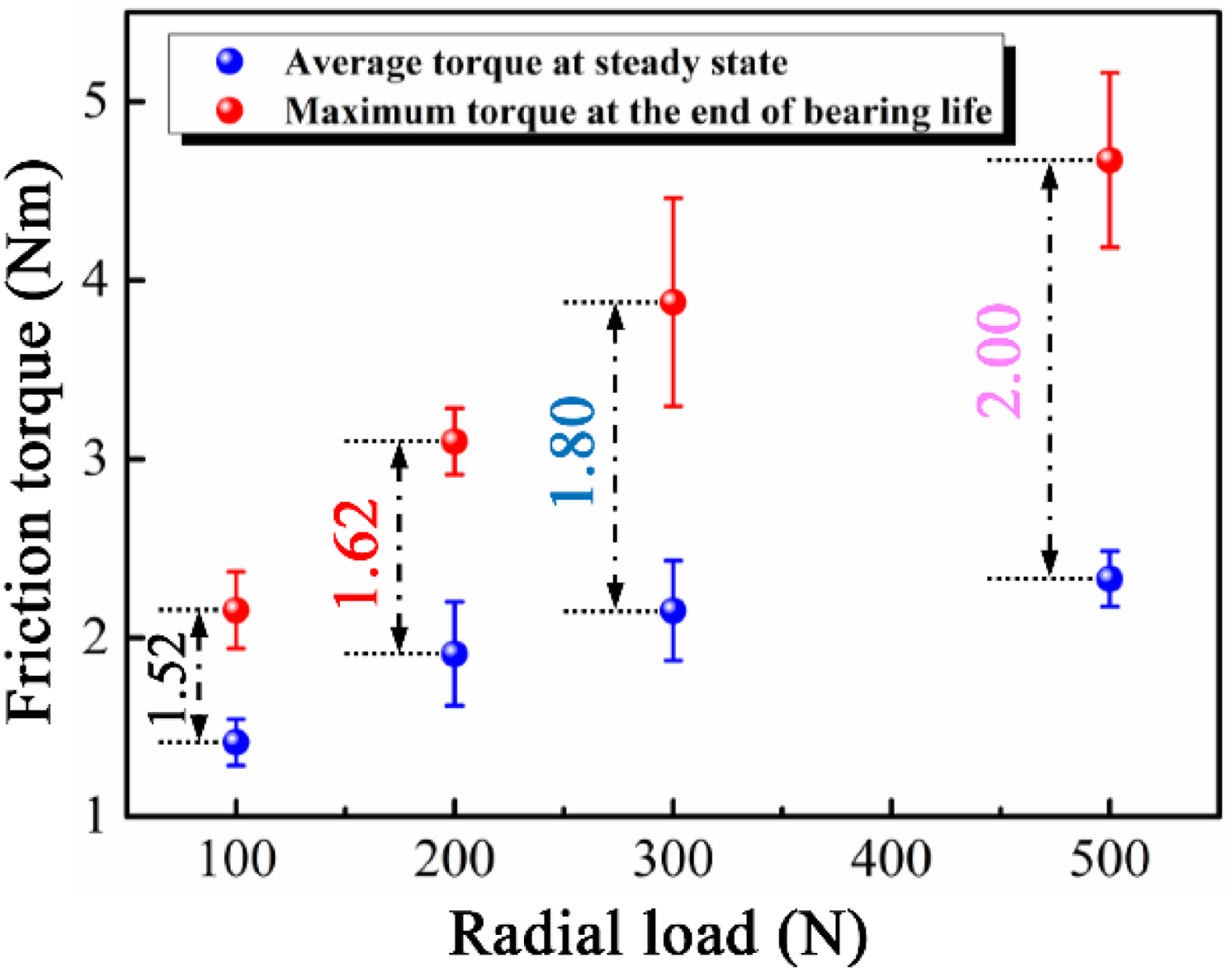
Figure 4 presents the service performance change curves of Type-1 bearings under different loads. The variation trend of the friction torque and temperature rise signal could reflect the evolution law of bearing performance. It is obvious that the macro signal of Type-1 bearings under different loads presented a “three-stage” characteristic of typical coated SPBs, which could be divided into “running stage,” “steady stage,” and “signal mutation stage.” 23 As shown in Figure 5, the maximum torque value during the signal mutation stage was approximately 1.5∼2.0 times of the average torque value at the steady-state stage through statistics. Therefore, Type-1 bearings had failed. Moreover, the average and the maximum friction torque increased gradually with the load. The average torque values during the steady-state stage were lower than 2.5 Nm. It indicated that the service performance of Type-1 bearings was obviously better than ordinary civil SPBs. 22 Bearings had the best performance and life at 100 N (in Figure 4(a) and (b)). More specifically, during the steady-state stage, the signals changed steadily and the average torque value was less than 1.5 Nm. The service life is approximately 148,000 cycles. Load significantly reduced the bearing life. The bearing life decreased to approximately 84,500 cycles when the load increased to 200 N. When the load is 500 N, the bearing life was only less than approximately 40,000 cycles. The life was lower than that of ordinary civil bearings under the same loads. The above results show that Type-1 bearings had better service performance, but their life had not been significantly extended.
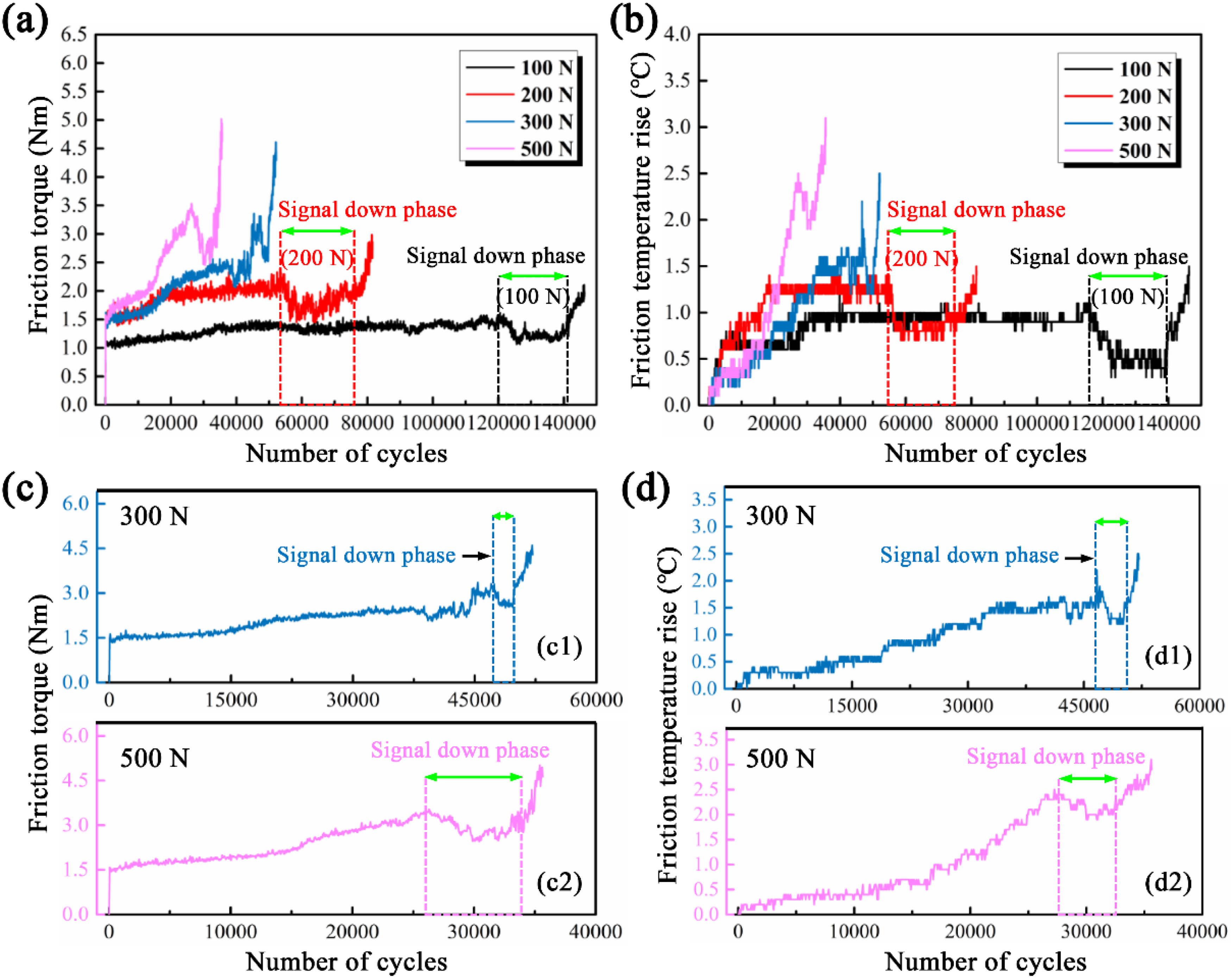
Life test results of type-1 bearings: (a) variation curves of friction torque and (b) friction temperature rise; (c) friction torque, and (d) friction temperature rise at 300 N and 500 N.
The average torque value of Type-1 bearings at different stages under different loads.
Interestingly, an obvious signal down stage occurred before the signal mutation stage of the bearings under different loads. A similar stage had never appeared in previous studies. As shown in Figure 4(a) and (b), torque and temperature rise had corresponding change characteristics. The signal down stage lasted longer at 100 N and 200 N (approximately 25,000 cycles at 100 N, and approximately 20,000 cycles at 200 N). The life of the bearings decreased significantly, and the fluctuation of the torque and temperature rise was gradually intensified with the increase of load. However, there was still an obvious signal downstage in the late stage (in Figure 4(c) and (d)). Even if it lasted for the very short cycles. The signal down stage avoided the unpredictable and sudden failure of the bearings. When the macroscopic signals decreased and maintained for a period of cycles, it could infer that bearing was about to fail. Therefore, we could use the special signal change law of Type-1 bearings during running to prevent the failure. Life test results show that Type-1 bearings had a “failure warning function.”
Service performance of Type-2 and Type-3 bearings
To investigate whether the bearing still has “failure warning function” after the coating strategy was changed. Subsequently, the life tests of single-side coated bearings (Type-2 and Type-3 bearings) were carried out at 100 N and 200 N. As shown in Figure 6, the service process of both types of bearings also conformed to the “three-stage” characteristic, indicating that they failed. The test results indicate that the life of Type-2 bearings was significantly better than Type-3 bearings. The maximum life of Type-2 bearings was approximately 146,000 cycles at 100 N, which was similar to Type-1 bearings. However, the maximum life of Type-3 bearings at 100 N was only less than 25,000 cycles. According to statistics, the life of Type-1 and Type-2 bearings was approximately 5.8 times that of Type-3 bearings. Besides, the average friction torque value of Type-2 and Type-3 bearings was higher than Type-1 bearings under the same load. The fluctuation of torque and temperature rise signals was also greater than Type-1 bearings. The above results show that the service performance of Type-1 bearings was better than Type-2 and Type-3 bearings. However, the life of Type-1 bearings was similar to Type-2 bearings, and Type-3 bearing was the worst. Inner ring coating was more effective in improving the bearings performance compared with the outer ring coating. The method of double-sided coating was obviously more advantageous through comparative tests.
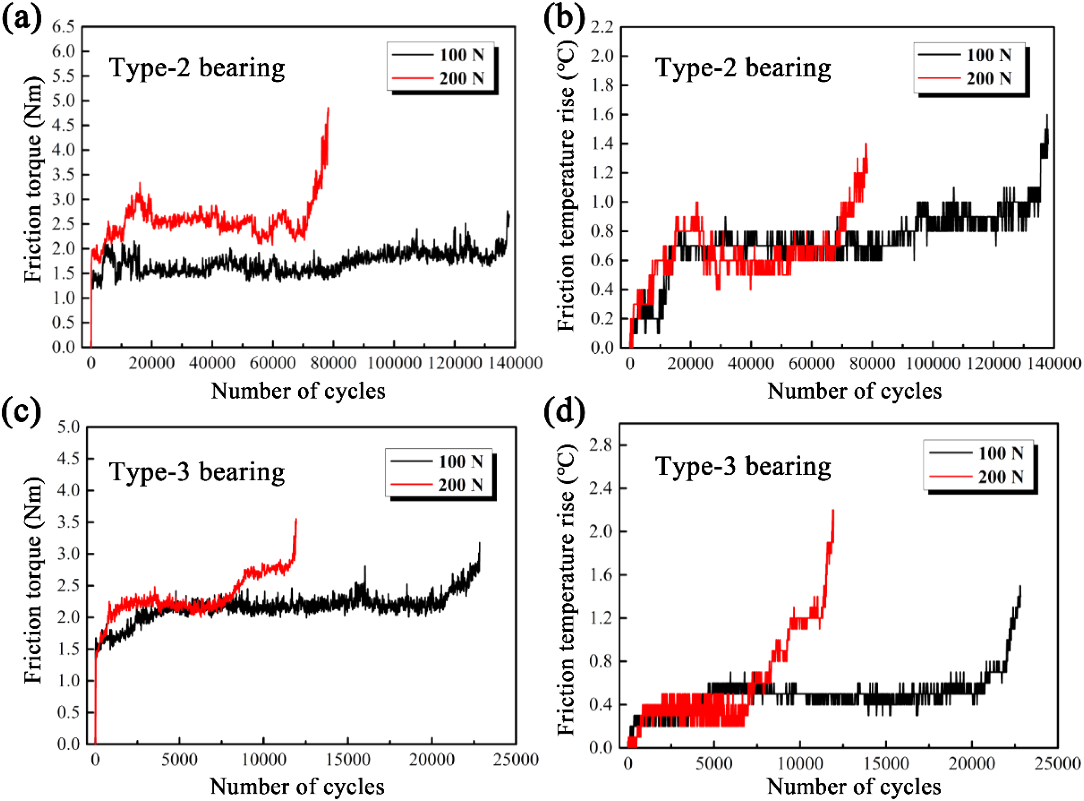
Life test results of Type-2 and Type-3 bearings under different loads: (a) variation curves of friction torque, and (b) variation curves of friction temperature rise of Type-2 bearings; (c) variation curves of friction torque, and (d) variation curves of friction temperature rise of Type-3 bearings.
Moreover, no obvious signal downstage was found during the whole life cycle of Type-2 and Type-3 bearings. As shown in Figure 6(a), a short signal downstage appeared during the running of Type-2 bearings at 100 N. However, as shown in Figure 6(b), no corresponding signal down stage was found in the friction temperature rise curve. It can be inferred that it was a normal signal fluctuation. Based on the above analysis, it can be further speculated that the signal downstage of Type-1 bearings might be caused by the interaction of inner ring coating and outer ring coating. To further investigate the formation mechanism of the signal falling stage, the microwear morphology and failure mechanism of three types of bearings are analyzed in the next section.
Wear failure behavior of type-1 bearings
To ensure the consistency of microscopic characterization, the most severely worn areas of bearings conditions were analyzed for each load. Figure 7 demonstrates SEM micrographs of the double-sided coated bearings (Type-1 bearings) and corresponding EDS analysis.
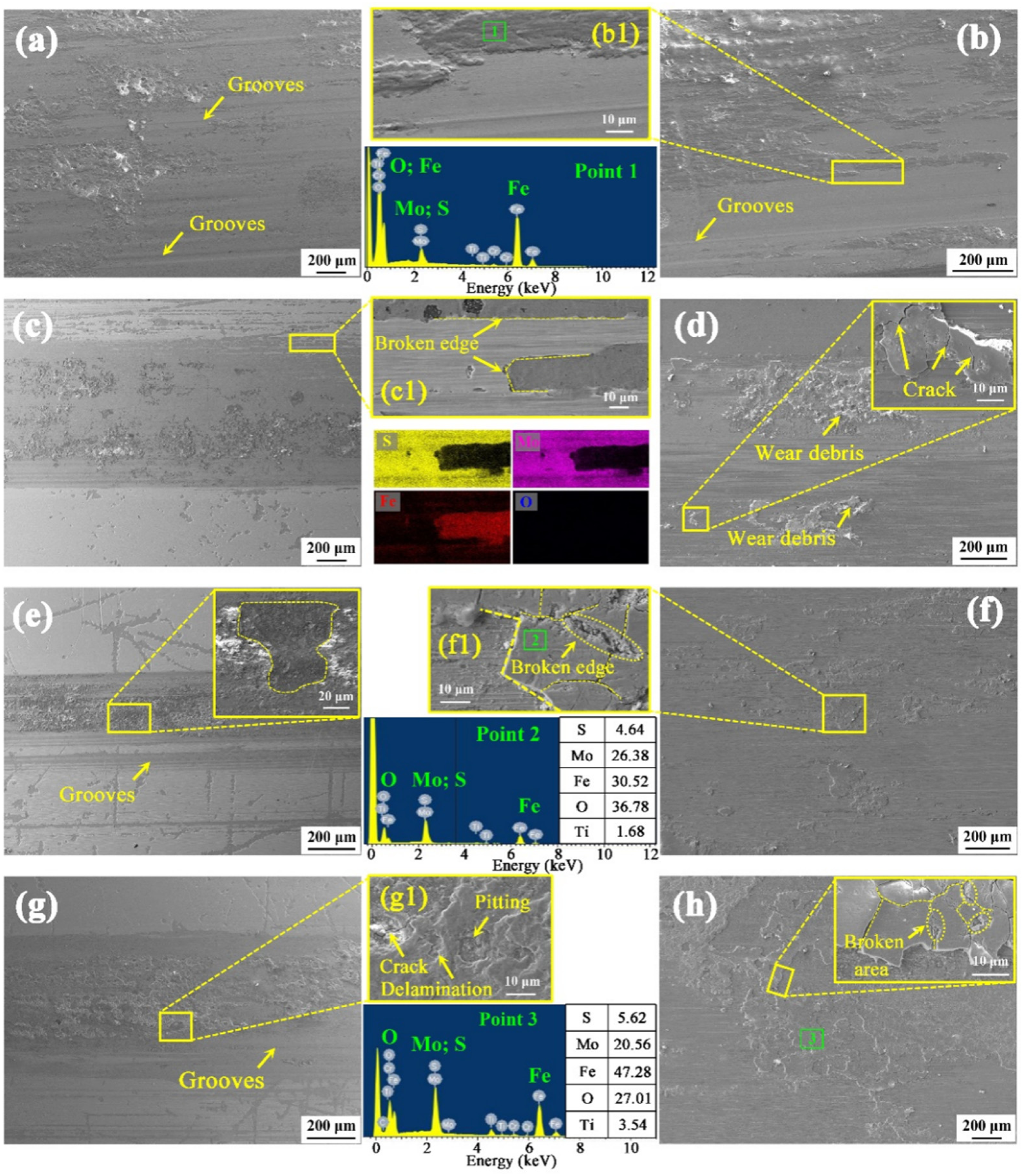
Wear morphology of type-1 bearing: (a) SEM images of inner ring, and (b) outer ring at 100 N; (b1) enlarged images of (b); (c) SEM images of inner ring, and (d) outer ring at 200 N; (c1) enlarged images of (c); (d1) enlarged images of (d); (e) SEM images of inner ring, and (f) outer ring at 300 N; (e1) enlarged images of (e); (f1) enlarged images of (f); (g) SEM images of inner ring, and (h) outer ring at 500 N; (g1) enlarged images of (g); (h1) enlarged images of (h).
A large area of metal substrate was exposed on the spherical surfaces of the SPBs, and severe damage occurred on the substrate. The above phenomenon further confirmed that the bearings failed. Firstly, as shown in Figure 7(a) and (b), a large number of deep grooves along the sliding direction were observed on the exposed substrate at 100 N. The same grooves were found on the bearing surfaces of other loads (in Figure 7(c), (e) and (g)). Therefore, severe abrasive wear was one of the main causes of bearing failure. Moreover, as shown in Figure 7(b), (d), (f), and (h), a lot of wear debris was distributed on the outer ring surfaces. The EDS results of point 1–3 indicated that the wear debris was mainly composed of a large number of O and Fe elements and a small number of Mo and S elements (in Figure 7(b1), (f1), and (g1)). Specifically, O content was approximately 27%∼40%, Fe content was approximately 30%∼50%, Mo content was approximately 20%∼25%, and S content was approximately 4.6%∼6.0%. It can be inferred that the oxidation products of the substrate and MoS2 were the main sources of abrasive particles. 43 Therefore, oxidative wear also occurred simultaneously. The third body (oxide) caused serious abrasive wear.
Then, as shown in Figure 7(d), (f), and (h), many cracks appeared on surfaces of the central wear area with the load increased, indicating that fatigue wear occurred. The delamination on the bearing inner ring surface at 500 N also proved this. The cracks and delamination gradually increased with the load, and fatigue wear became more severe (in Figure 7 (f1), (g1), and (h1)). Fatigue wear gradually dominated. Moreover, the repeated extrusion of the inner and outer rings led to secondary fragmentation of the transfer film on the outer ring surface. Broken areas of different sizes were formed on the surface of the transfer films under local stress (as shown in Figure 7(d1), (f1), and (h1)), which led to crack propagation. 44
As mentioned earlier, there are many thin sheets of wear debris adhered to the outer ring surface. To further analyze the formation of lubricating debris, the coating shedding area at the edge of the wear scar was observed. The inner ring coating had fallen off in the form of local pieces or blocks with regular edges (in Figure 7(c1)). This indicates that the coating was broken by an uneven stress before falling off. Combined with the existing studies,45,46 the coating experienced a process of “breaking–shedding–transfer–adhesion” under cyclic stress. Consequently, the lubricating debris were transferred to the surface of outer ring. A transfer film was formed. As shown in Figure 7(f1) and (h), EDS analysis of the transfer film indicates that Mo, S, O, and Fe were the main elements, further confirming that the transfer film on the outer ring surface came from the inner ring coating (a-C:H/MoS2 coating). 41 Besides, as shown in Figure 7 (e) and 7 (g), the pitting on the inner ring indicates the occurrence of adhesive wear. Adhesive wear seemed to occur under higher loads (300 N and 500 N). Because the inner ring coating was softer than the outer ring coating. As shown in Figure 4, the increase in load caused sharp rise in friction temperature, and plastic deformation occurred on the local surface of the coating. Therefore, the plastic deformation of the contact peak of the inner and outer ring coatings and the transient temperature rise caused the coating to soften and produced welding, forming the adhesive wear. 40 Some large and deep adhesive pits were formed after adhesive damage under shear stress (as shown in Figure 7(e1) and (g1)).
From the above discussion, with the increase of load, the failure mechanism of Type-1 bearings gradually changed from abrasive wear to fatigue wear and adhesive wear. Oxidation wear mainly caused the failure of the lubricating coating during the end stage. More importantly, relatively complete and large area transfer films were observed on the outer ring surfaces. To further analyze the composition of transfer films, which were characterized (in Figure 8), EDS results demonstrate that S, Mo, C, and O occupied the main area of the worn surface. Their distribution was relatively uniform. Moreover, combined with the Raman spectra, it can be inferred that the mixed transfer film after failure was mainly composed of MoS2, oxides of Mo and carbon. Although most of the transfer films oxidized and failed. They provided self-lubrication for bearings before failure. Self-lubricating layers on the spherical surfaces were gradually worn out with the service process of SPBs. The a-C:H/MoS2 coating of the inner ring was transferred to the outer ring surface and gradually formed a large area of complete mixed friction transfer film, which provided a certain lubrication for the bearing. 47 These provided an explanation for “signal down stage” of Type-1 bearings.
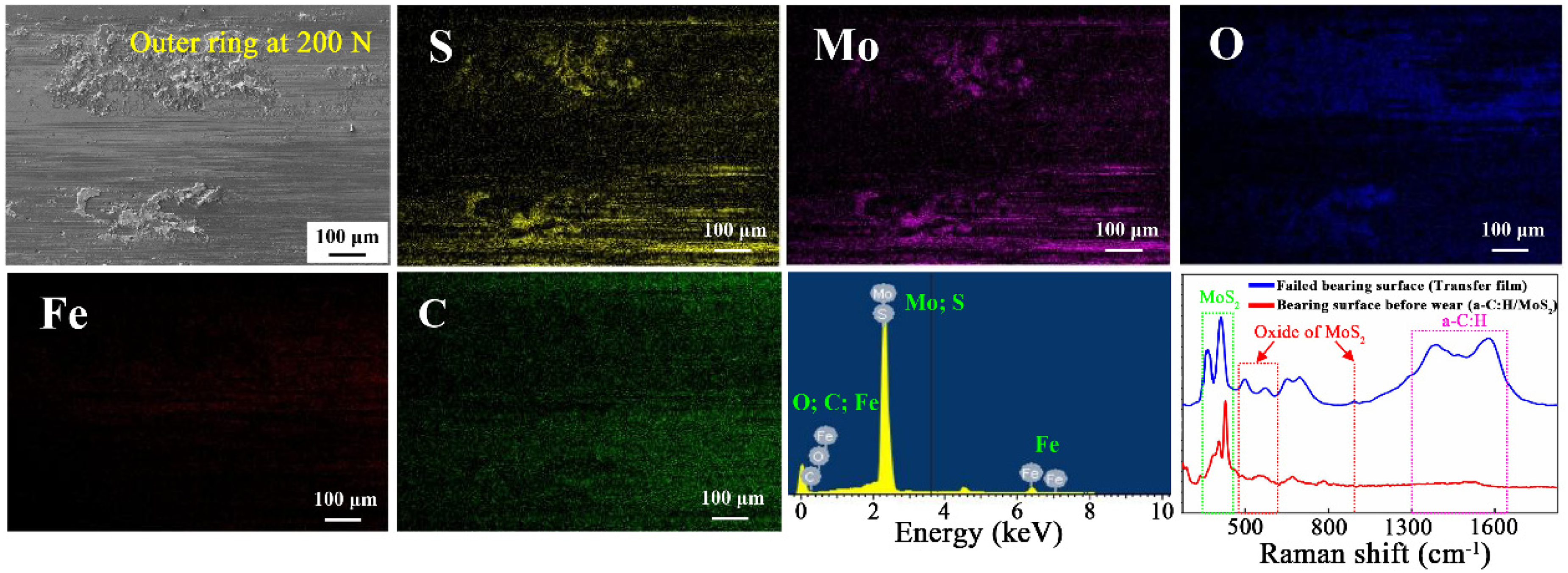
Characterization of the typical mixed friction transfer film on the inner spherical surface of the outer ring of Type-1 bearings at 200 N.
Wear failure behavior of Type-2 and Type-3 bearings
Figure 9 demonstrates the wear morphology of inner ring coated bearings (Type-2 bearings). In Figure 9(a), (b), (e), and (f), a large area of the metal substrate was exposed in the central wear area of the inner and outer rings at 100 N. At the same time, grooves, delamination, and crack propagation were discovered. These indicate that abrasive and fatigue wear mainly caused the bearing failure. According to EDS results, the increase of O content indicates that oxidation wear occurred in the local areas. The remaining lubricating coatings were still distributed on the surface of the inner ring, but they were oxidized and failed. Different from Type-1 bearings, there is no complete transfer film formed on the outer ring, and only a small amount of inner ring coatings was scattered on the substrate. In addition, the local spalling and delamination became more severe with the increase of load at 200 N (in Figure 9(c) and (d)). Adhesive wear and fatigue wear dominated. Correspondingly, EDS results show that the Fe content on the bearing surfaces was as high as 81.42% and 77.34% respectively. The O content was 12.95% and 19.07% respectively. The Mo and S contents were a little. The above results indicate that the inner ring coatings of the Type-2 bearing were completely removed, and there were no transfer films on the outer ring.
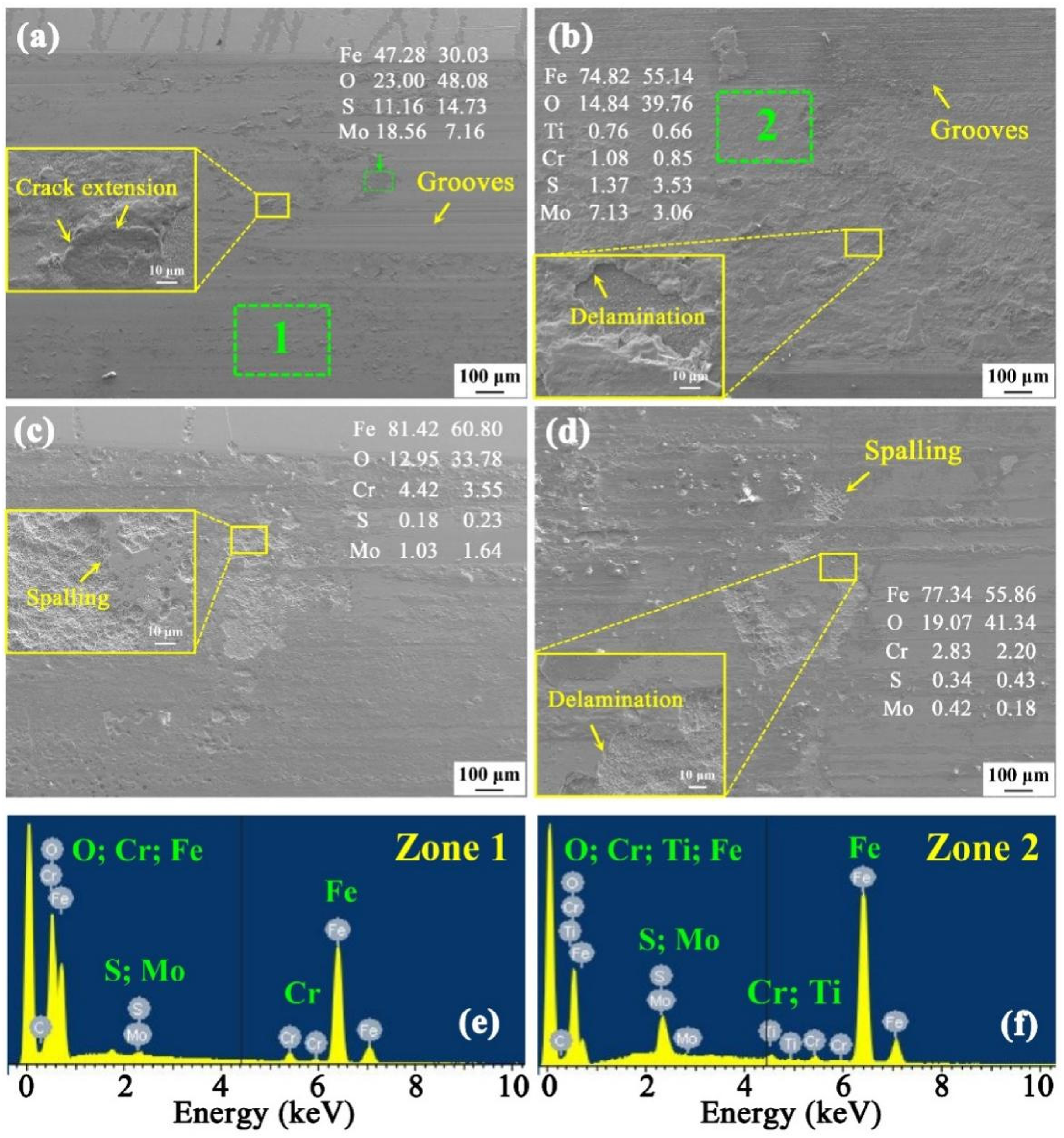
Wear morphology of Type-2 bearing at 100 N and 200 N: (a) SEM images and EDS analysis of the inner ring, and (b) the outer ring at 100 N; (c) SEM images and EDS analysis of the inner ring, and (d) the outer ring at 200 N; (e) EDS energy spectrum of Zone 1 of (a); (f) EDS energy spectrum of Zone 2 of (b).
Figure 10 demonstrates the wear morphology of Type-3 bearings (only the outer ring was coated) under different loads. As shown in Figure 10(a), (b), (e), and (f), a large area of the metal substrate was exposed in the central wear area of the inner and outer rings. Compared with Type-1 and Type-2 bearings, more severe damage occurred on the contact surface of Type-3 bearings. At the same time, the grooves and the delamination of the outer ring surface became more obvious with load. Therefore, the severe abrasive wear and fatigue wear mainly caused Type-3 bearing failure. Moreover, as shown in Figure 10 (a) and (c), a large amount of “black films” were distributed on the inner ring. EDS results verify that Fe and O contents were high on the surface of the “black films.” Therefore, this was the oxide film produced by the oxidation wear of the metal substrate, which did not have lubricity. 48 The above results indicate that there were no transfer films on the contact surfaces of Type-3 bearing. The substrate also suffered from severe abrasive wear and oxidation wear, and the bearing completely failed.
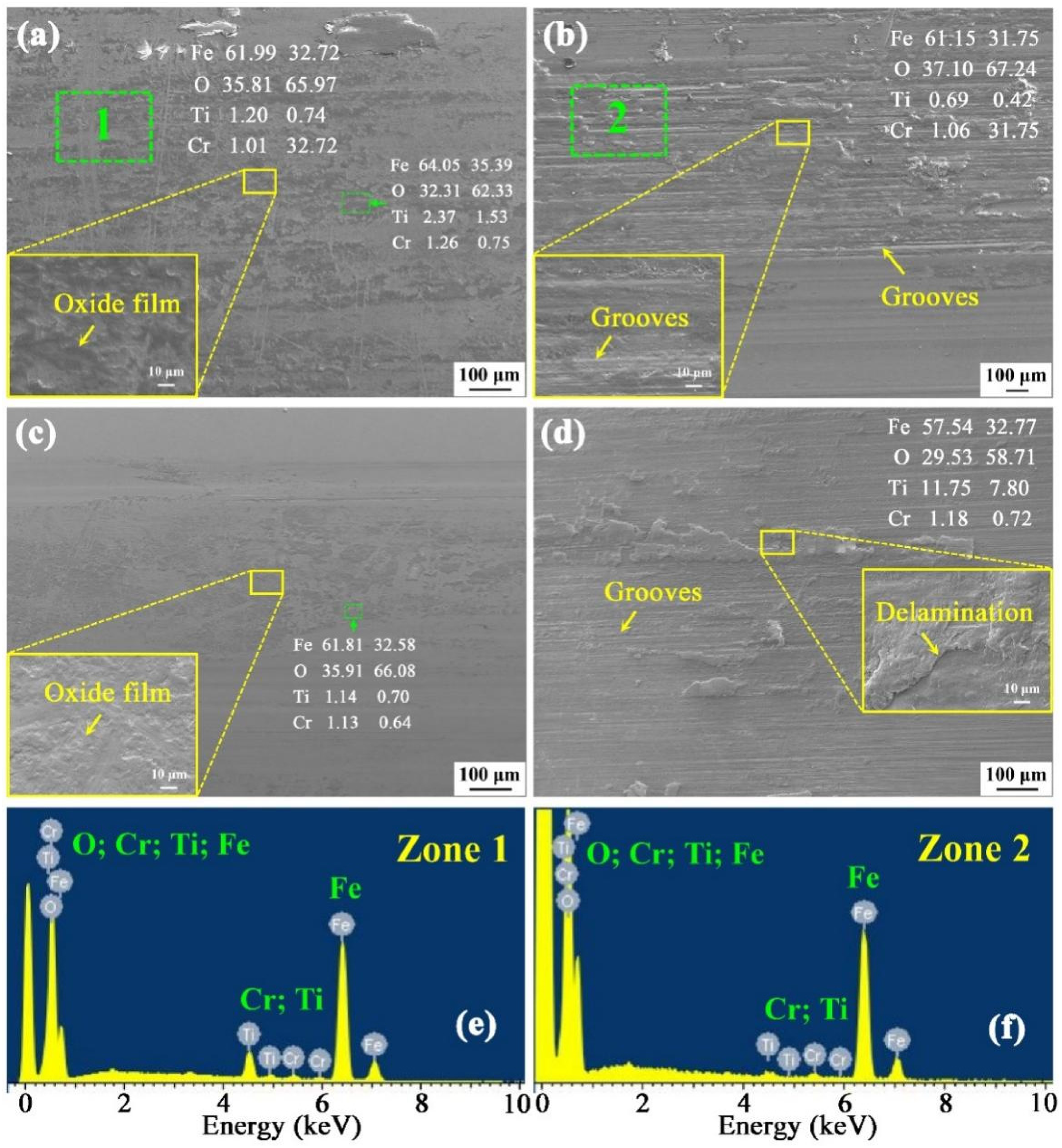
Wear morphology of Type-3 bearing at 100 N and 200 N: (a) SEM images and EDS analysis of the inner ring, and (b) the outer ring at 100 N; (c) SEM images and EDS analysis of the inner ring, and (d) the outer ring at 200 N; (e) EDS energy spectrum of Zone 1 of (a); (f) EDS energy spectrum of Zone 2 of (b).
Effects of self-lubricating coatings on performance enhancement of the bearings
From the above test results and discussion, it can be concluded that the large area and complete mixed friction transfer films on the surfaces of the bearing were the main reason for the appearance of the signal down stage. Among the three types of GE17E/HEK bearings, only double-sided coated bearings (Type-1 bearings) have the complete transfer film formed on the surface of the inner and outer rings. The previous tests indicate that the low sheer force of MoS2 and graphitization of a-C: H reduced the friction coefficient in the interface. 42 More specifically, the layered structure of MoS2 promoted inner ring coating to rapidly form transfer film. a-C:H film, as the foundation of the MoS2 film, further improved the adhesion and enhanced the bearing capacity of the inner ring coating.41,49,50 In our studies, the load of the bearing life tests was much higher than material tests. The test results confirm that a-C:H/MoS2 coating improved the service performance of the bearings (in Figure 4 and Figure 6). It can be inferred that the transfer film was mainly derived from the inner ring coating (in Figure 7). However, the signal down stage was not discovered during the whole life of the Type-2 bearings (in Figure 6(a) and (b)). Correspondingly, a complete transfer film was not formed on the surface of the inner and outer rings. It can be inferred that the complete transfer film could not be formed only based on the inner ring coating. The outer ring coating (a-C: H coating) further improved the adhesion of the transfer film when the a-C:H/MoS2 coating moved to the surface of the outer ring.41,43,51–53 Therefore, the transfer film mainly came from the a-C:H/MoS2 coating on the inner ring surface, and the a-C: H coating on the outer ring surface improved the adhesion of the transfer film. The interaction of the two coatings prevented the transfer film from wearing out too quickly.
In this article, double-sided coated was obviously a better method. The interaction of a-C: H/MoS2 coating and a-C: H coating resulted in the following beneficial effects for bearings: (a) new “failure warning function.” Large area and complete transfer film provided lubrication at the end of the bearing life, avoiding sudden failure; (b) enhancement of the performance and life. Self-coatings improved the tribological performance of the bearings and extended their life to a certain extent under light-load conditions. However, the current coating strategy limited the effect on improving bearing life.
Conclusions
In this article, a new coated self-lubricating SPB (type GE17E/HEK) was developed by applying high-performance lubricating coatings to the spherical surfaces. Whole life tests were carried out to compare and investigate the service performance and wear failure mechanism of different coated bearings under light loads. The conclusions are as follows.
Inner ring coating (a-C: H/MoS2 coating) played a major role in improving the service performance of bearings, whereas outer ring coating (a-C: H coating) had subsidiary effects. Therefore, double-sided coated bearing (Type-1 bearing) and inner ring coated bearing (Type-2 bearing) had better service performance. The load had a great effect on the service life of bearings. The life of the three types of bearings decreased significantly with the load. The large area and complete mixed friction transfer film mainly came from a-C: H/MoS2 coating on the inner ring, and a-C: H coating on the outer ring improved its adhesion. The transfer film could provide a certain lubrication for the bearing in the later stage of service, which further explained the generation of the signal down stage. Thus, the interaction of the two coatings provided “failure warning function” for Type-1 bearings. The wear failure mechanism of bearing gradually changed from severe abrasive wear to fatigue wear and adhesive wear with the load. Besides, oxidation wear was the main cause of transfer film failure.
Footnotes
Declaration of conflicting interests
The authors declared no potential conflicts of interest with respect to the research, authorship, and/or publication of this article.
Funding
The authors disclosed receipt of the following financial support for the research, authorship, and/or publication of this article: This work is funded by the National Nature Science Foundation of China (52122508, 52005511, 52205225), and the Pre-Research Program in the National 14th Five-Year Plan.