
Abstract
An air bearing system with active electromagnetic assistance is proposed, and its dynamic characteristics are numerically analysed. The system is based on herringbone groove hydrodynamic journal bearings. The air bearing system adopts electromagnetic force to assist in lifting the rotor and lowering the lift-off speed of the bearing and adjusting the dynamic stiffness. The characteristics of the bearings are examined using the two-way coupled fluid-structure interaction method for different operating environments. The fluid simulation is performed in ANSYS Fluent and coupled with the motion equations. The fluid-structure interaction analytical model is cross-examined with the published experimental results and is used to analyse the proposed system. The results demonstrate that the lift-off speed is lowered by 46.04% and that the electromagnetic force can compensate for the loss of stiffness at an altitude of 4000 m.
Keywords
Introduction
Hydrodynamic air bearings are widely used in high-speed turbomachinery.1–3 It holds the advantage of supporting oil-free and high-speed rotations. The hydrodynamic air bearing is simple in design and light in weight because no external lubrication system or pressurised gas is required. This allows for a compact rotor-bearing system design, which is suitable for mobile devices, particularly in aerospace engineering.4,5
Hydrodynamic air bearings may suffer from wear due to the contact between the bearing sleeve and the rotor, which may lead to system failure. 6 Some dry lubrication methods have been developed to address this issue for general applications. 7 However, the known lubricants cannot cope with extremely high working temperatures beyond 1100 oC, 8 while micro gas turbine engine rotors are constantly working at 1200 oC. In such applications, lifting the weight of the rotor can reduce wear and extend the life of the bearing.
Besides, the hydrodynamic air bearing is sensitive to the operating environment, as its performance is affected by the temperature, atmospheric pressure and gas properties. 9 Thus, when designing a rotor system with air bearings, a suitable working environment should be addressed. If the bearing performance is seriously compromised, the rotor dynamics characteristics are impacted, putting the stability at risk. Electromagnet (EM) assisted bearing system provides a means to adjust the loading of the rotor and improve its performance.
Researchers have developed various approaches to tackle the above-mentioned wear problems. Applying solid lubricant is a promising solution to extend the life cycle of the hydrodynamic bearing. Solid lubricants can be powders, films, or composites. Dellacorte et al.10,11 applied the PS304 coating to foil bearings and successfully achieved more than 100,000 start/stop cycles. They aimed at the temperature range from cryogenic to over 650 oC. Solid lubricants are sensitive to changes in atmosphere and temperature. Temperatures above 1100 oC still pose a challenge for the solid lubricant in the specific application of micro gas turbine engines. The ceramic matrix materials have been investigated for their suitability for use in high-temperature environments up to 1000 oC, 8 however, the availability of a suitable lubricant above this temperature range is limited.
The idea of combining the hydrodynamic air bearing with other components to reduce wear has been studied since the 1960s. Hydrostatic-hydrodynamic hybrid air bearing is one of the explored solutions. Hydrostatic air bearings hold the advantage of being contactless during the operation, and the grooves added to the hydrostatic bearing improve its threshold of instability. Fuller 12 conducted a thorough review on the hybrid air bearing back in 1969 and concluded some early research on the topic. Lund et al.13,14 developed the experiments and calculation model for the hybrid air bearing. They also studied the orifice feeding hole design and its effects on the stability of bearings. There were numerous studies on hydrostatic and hydrodynamic hybrid air bearings, which proved to be useful, but the disadvantage of requiring an external compressor is obvious.
The use of the EMs attracted researchers’ attention. Beek et al. 15 combined the EM with a hydrostatic thrust bearing, where the EM is used for preloading air bearings and achieving better running accuracy and higher bearing stiffness. Huang and Chang 16 developed a magneto-aerostatic hybrid bearing that used an axial passive magnetic bearing to reduce the axial vibration and increase the thrust bearing capacity. Morosi and Santos 17 studied a system in which permanent magnets were combined with a hydrodynamic bearing. The low-speed load-carrying capability of the hydrodynamic bearing was improved by carefully offsetting the magnets, but they also found that the magnets were difficult to control. In the development of active magnetic bearings (AMB), the combination of AMB and air bearings are popular. Jang et al. 18 developed the hydrostatic bearing and AMB hybrid system and successfully improved the high-speed stability of the system, but the AMB increased the complexity of the system. The combination of the hydrodynamic bearing and the active magnetic damper was studied by Looser and Kolar. 19 They improved the dynamic stability of gas bearings by introducing a self-sensing magnetic system.
This paper proposed a system that the herringbone groove hydrodynamic journal bearing (HGHJB) is assisted by EM. The EM force is applied for improving the performance of the HGHJB in two ways: by lowering the lift-off speed and by improving the bearing's dynamic stiffness. The EM force is used to assist in lifting the rotor and to reduce the lift-off speed. Lift-off speed is a crucial performance indicator of the technology. During start/stop operations, lowering the lift-off speed reduces the rotor's wear. The other function is to have an improved bearing characteristic to suit operating conditions. Adjustable stiffness and damping coefficients of the system can be achieved by delivering a constant EM force to the rotor and altering the eccentricity of the HGHJB. The control strategy of the system can be pre-defined according to the operational conditions, such as temperature and pressure. In contrast to the complicated and expensive AMB system, no feedback mechanism is required for control. Thus, the cost of the additional component is low and the added weight to the system is light. This paper explains the design of the system and its numerical analysis using the two-way coupled fluid-structure interaction (FSI) method developed using ANSYS Fluent and APDL. It combines the fluid and structure models, where the fluid model uses the finite volume method (FVM) to calculate air film pressures and the structure analysis model uses the finite element method (FEM) to compute rotor behaviours. 20 Through the fluid-structure interaction interface, the two models communicate data on fluid pressures and deformations using the dynamic mesh technique.
In the following section, the FSI method is introduced. The dynamic stiffness and damping coefficients are modelled using the FSI method and the results are verified against the published experimental results. The reduction of the lift-off speed and the adjustment of the stiffness of the HGHJB using the proposed system are investigated. The findings of this study are intended to expand the use of the HGHJB in industry and provide an alternative solution to hybrid air bearing systems.
The EM hydrodynamic air bearing system
The proposed system consists of HGHJBs and EMs. The structure is illustrated in Figure 1. HGHJBs are used to support the rotor, and two EMs are employed around the centre of gravity of the rotor to assist in lifting the rotor and improve the performance. The desired EM force and power supply can be obtained through calibration.
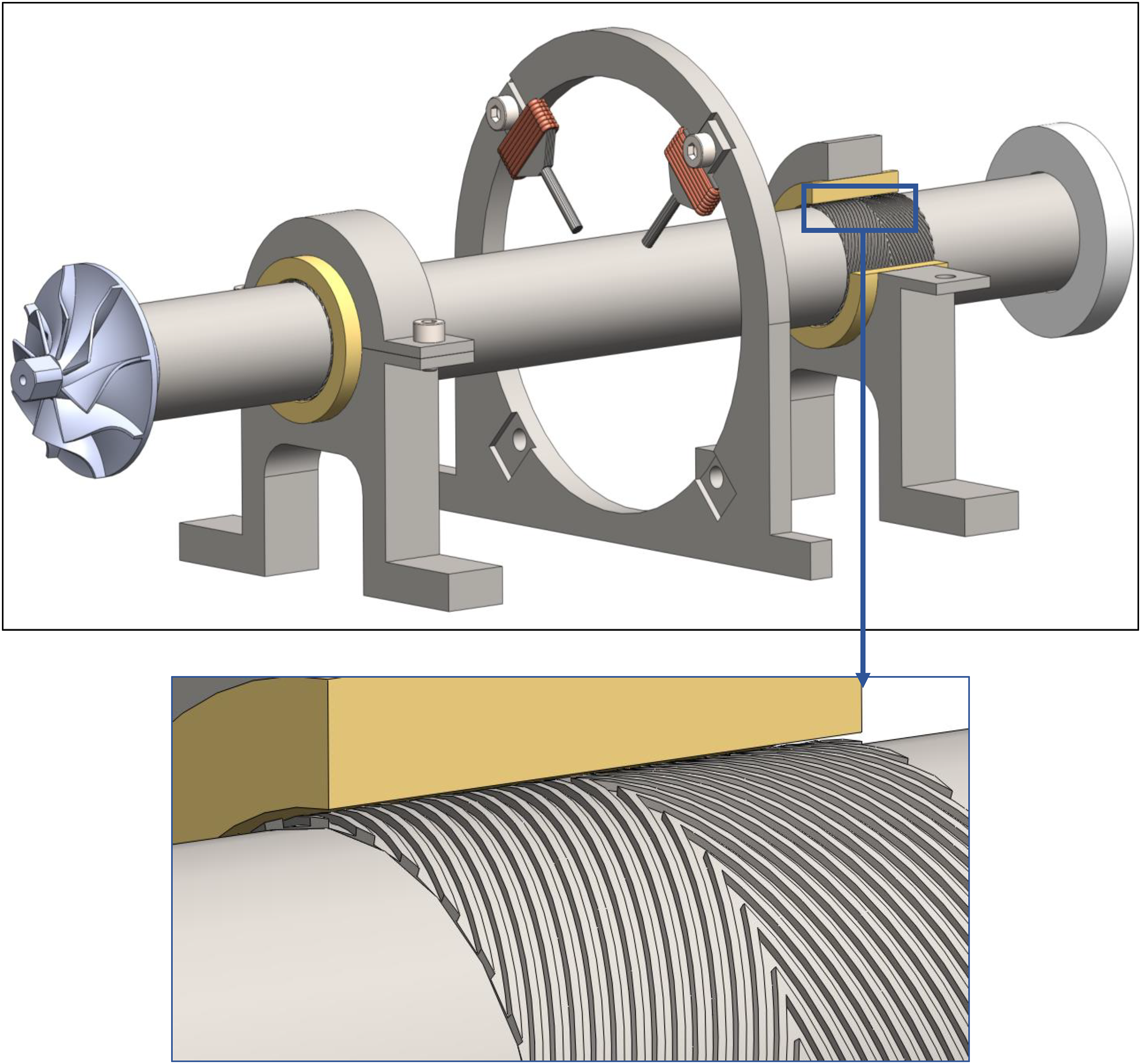
Conceptual drawing of the proposed air bearing rotor system.
The EM is designed in a probe shape, which is small and convenient to be placed. The flexibility of the design allows for a high degree of system integration. In Figure 1, the EMs are placed circumferentially around the rotor 90 degrees apart in angle. When both EMs are equally powered, the combined force is upwards against gravity.
The system can optimise the HGHJB in two ways: the EM force is applied to counter the gravity and lower the lift-off speed, and the EMs generate a constant force in response to operating conditions to compensate for HGHJB performance drop caused by changes in environmental pressure or temperature.
Numerical modelling of the HGHJBs
The FSI method
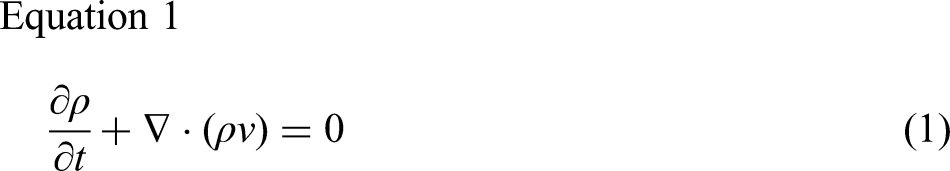
An FSI model has been developed for analysing the dynamic characteristics of the HGHJBs as well as the orbit of the rotor. The CFD model for compressible flow is based on the three conservation equations for compressible flow that are presented below. The conservation of mass equation, or continuity equation, can be written in Equation 1:
where
The equation of conservation of momentum in an inertial reference frame is described by:
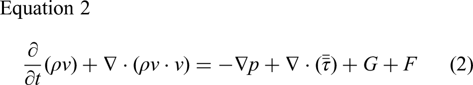
where p is the static pressure,
The definition of
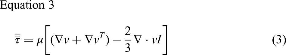
where
The equation of motion solved by transient dynamic analysis is
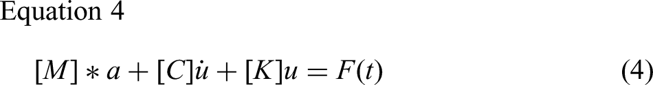
where
The conventional method of air bearing modelling is two-dimensional and simplifies the air bearing into a mass-spring-damper system. 21 The FSI approach makes no simplification in modelling the air film. It examines the interaction of the air film, rotor, and bearing sleeve, including fluid domain deformation, rotor position change, and sleeve geometry deformation due to pressure concentrations. Additionally, both the inertia and shear force of the fluid acting on the rotor surface is considered.
The CFD and the structure analysis models are running in parallel. The FLUENT generates the hydrodynamic forces and the simulation time and transfers them to APDL via the interfaces; APDL then transfers the rotor position and deformation calculated to FLUENT to update the fluid domain geometry. The data transfer happens at each time step, the data flow diagram is attached in Figure 2.
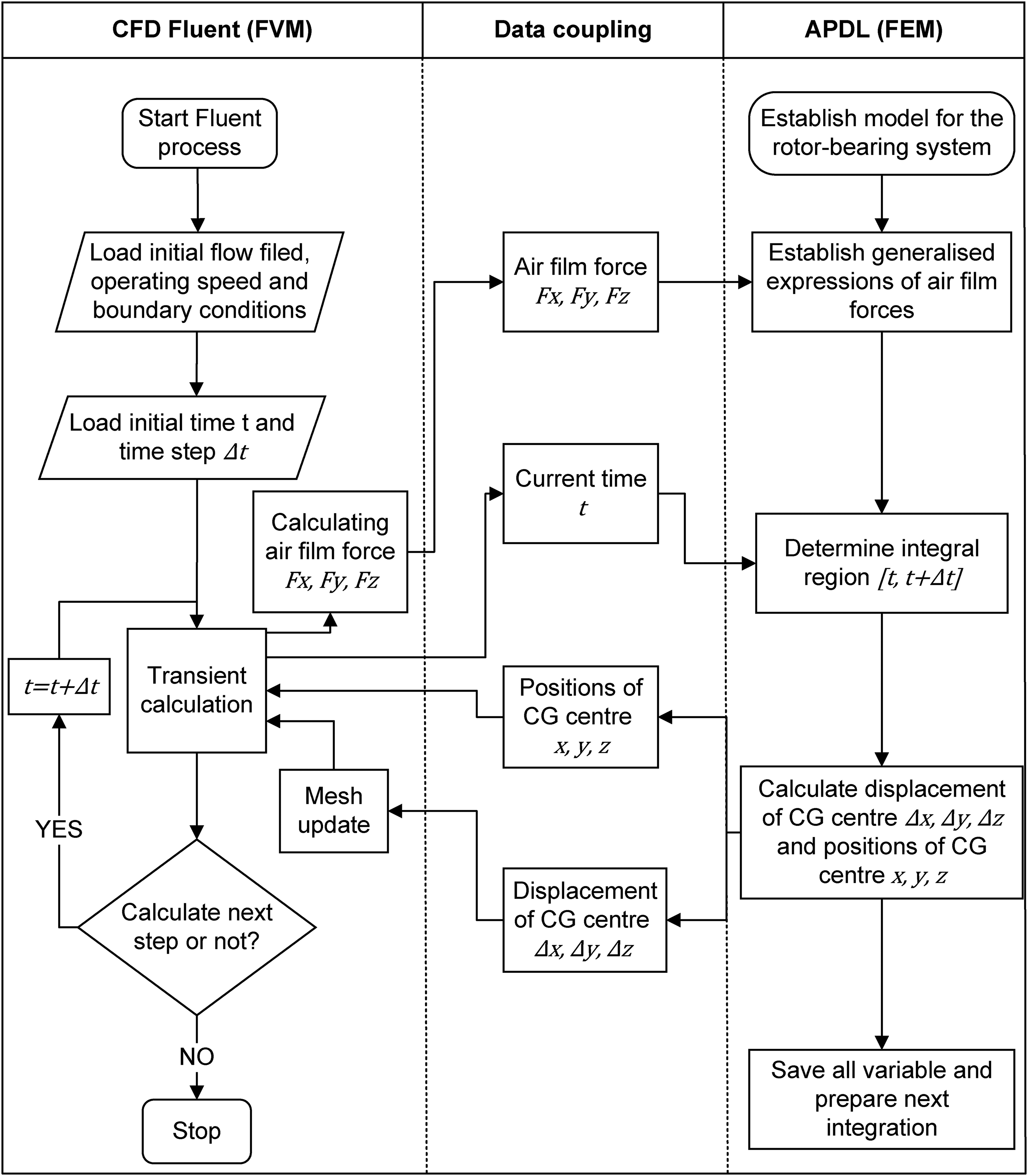
The flow diagram of the FSI coupling simulation process.
Model geometry and boundary conditions
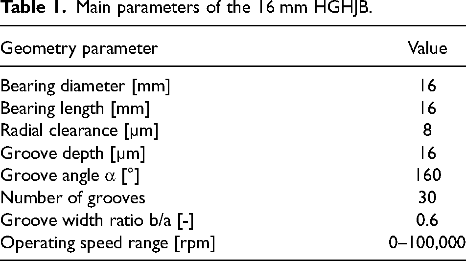
The tested rotor system employs two HGHJBs with a diameter of 16 mm. The length of the rotor is 176 mm, and the distance between the two journal bearings is 88 mm. The thickness of the thrust disk is 5 mm, and the diameter of the thrust disk is 28 mm. A turbine drives the test system, which is powered by compressed air. The specifications of the HGHJB are listed in Table 1 below, and the nomenclature of the groove parameters is shown in Figure 3.
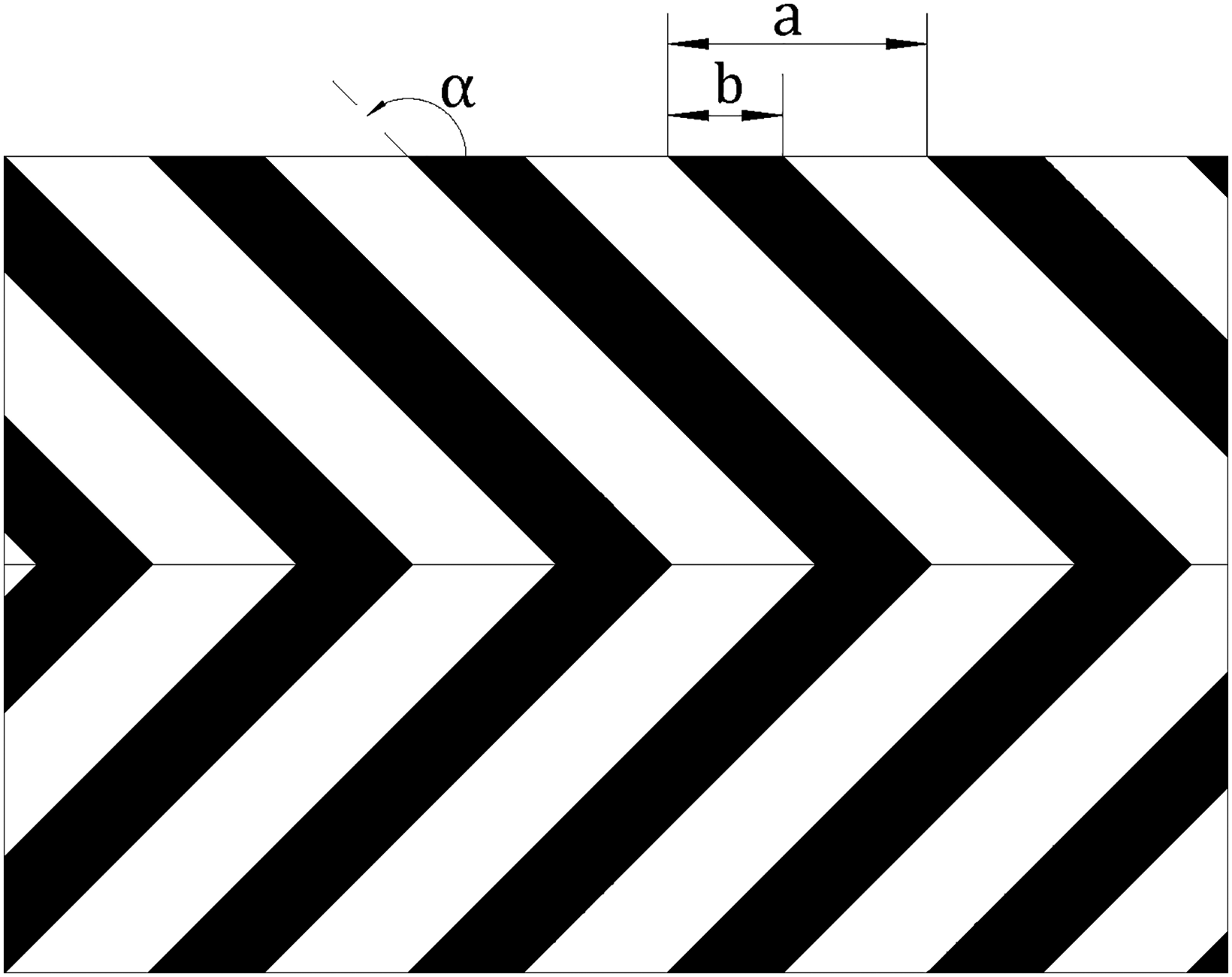
Nomenclature of the groove parameters.
Main parameters of the 16 mm HGHJB.
There are FSI interfaces between the inner bearing sleeve surface and the outer air film, as well as between the outer rotor surface and the inner air film surface. In the interaction between the sleeve and the air film, the main transferred information is the deformation in the bearing sleeve due to the fluid pressure concentration. After careful study of the pressure field, the deformation caused by the hydrodynamic pressure is found to be negligible. Hence the interaction interface connected to the sleeve is eliminated, and the outer surface of the air film model is fixed. The FSI interface between the rotor and the air film is critical in the simulation because it allows the rotor movement to be transferred to the fluid domain by imposing the displacement of the rotor to the deformation of the fluid domain. It also allows the hydrodynamic forces generated by the air bearing to be transferred to the rotor to limit its motion. The dynamic meshing used in the simulation is to re-mesh to accommodate the change of the rotor position, i.e., the thickness of the air film domain to account for the eccentricity.
The boundary conditions for the modelling are depicted in Figure 4, with the following details:
The inlet and outlet of the fluid domain are self-adaptive; the boundary condition is considered as pressure inlet but allows reverse flow when the pressure is built-up internally. The surfaces of fluid domains attached to the sleeve are set as fixed walls, whilst the surfaces of fluid domains connected to the rotor are set as FSI interfaces. The axial movement of the rotor is fixed.
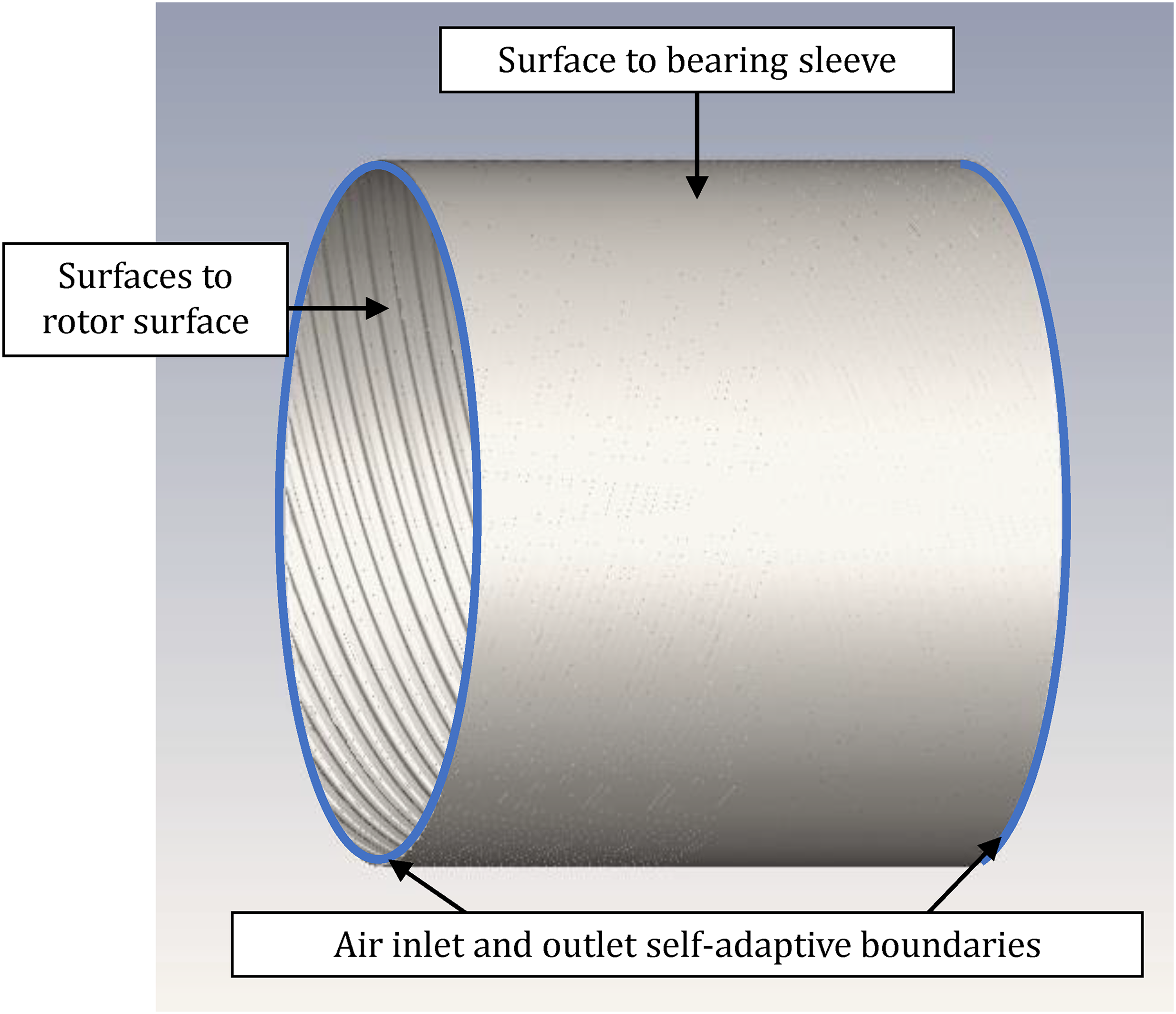
The boundary conditions of the fluid domain.
The air involved is regarded as compressible in the modelling, and the compression ratio is a variable in the energy equation. The initial temperature of the simulation is 300 K, with corresponding air density and viscosity; the heat caused by the rotor and the air friction can be passed to the sleeve. The rotor's initial position is concentric to the bearing sleeve. An example of the contour of pressure distribution is shown in Figure 5.
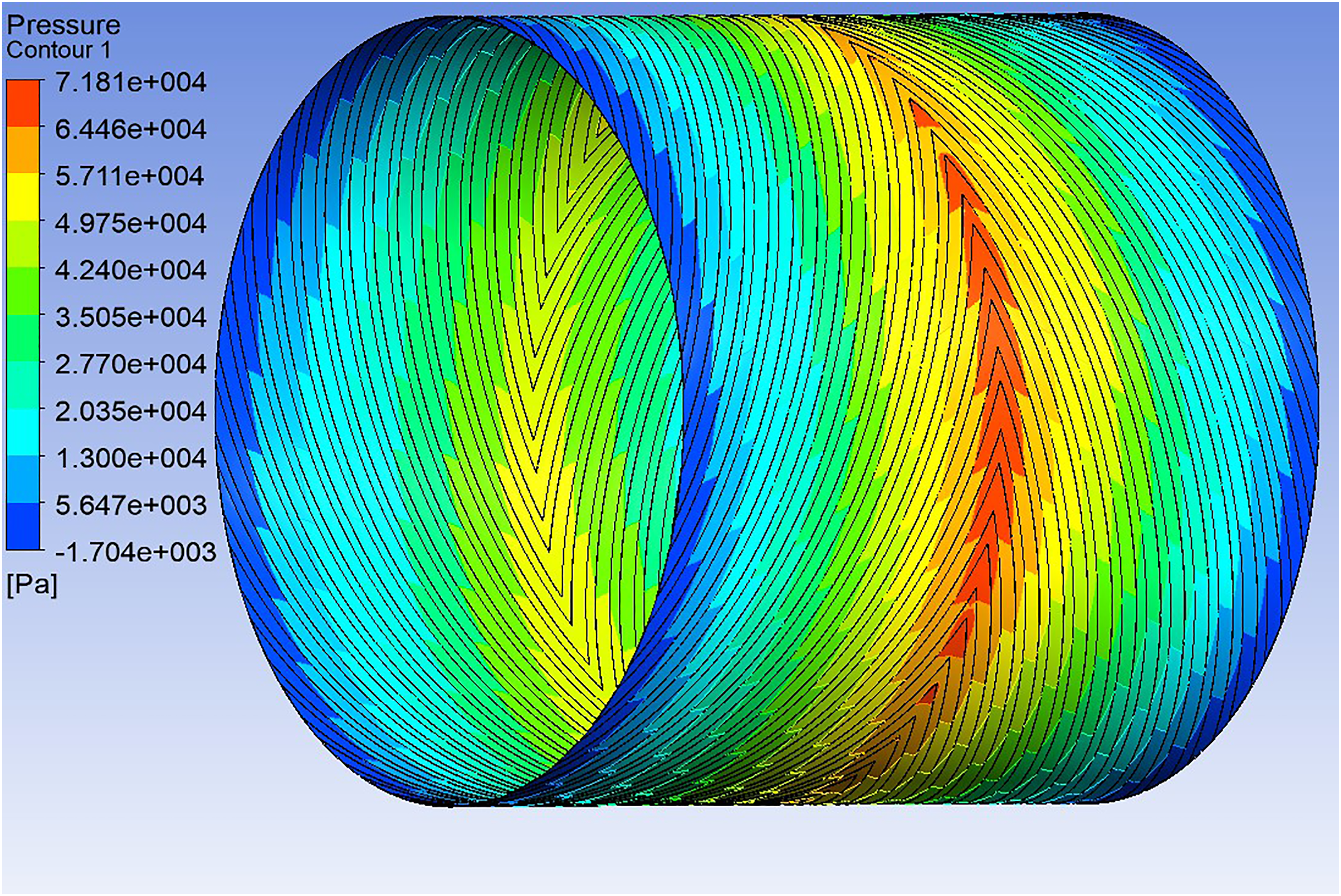
An example of the pressure distribution contour of the 16 mm HGHJB.
Development of the FEM and FVM model
In the simulation of air bearings, the meshing of the fluid domain inherently faces many challenges. The high aspect ratio of the air film geometry requires a large mesh element number to keep the element aspect ratio low. On top of it, the dynamic meshing model requires mesh elements with a high orthogonal ratio and low skewness. At the same time, the total element numbers should be kept low to make the transient simulation time reasonable. The structured hexahedron grids are generated to address the problems. The mesh grid is demonstrated in Figure 6, and the layered mesh elements are generated to fully capture the velocity gradient of flow.
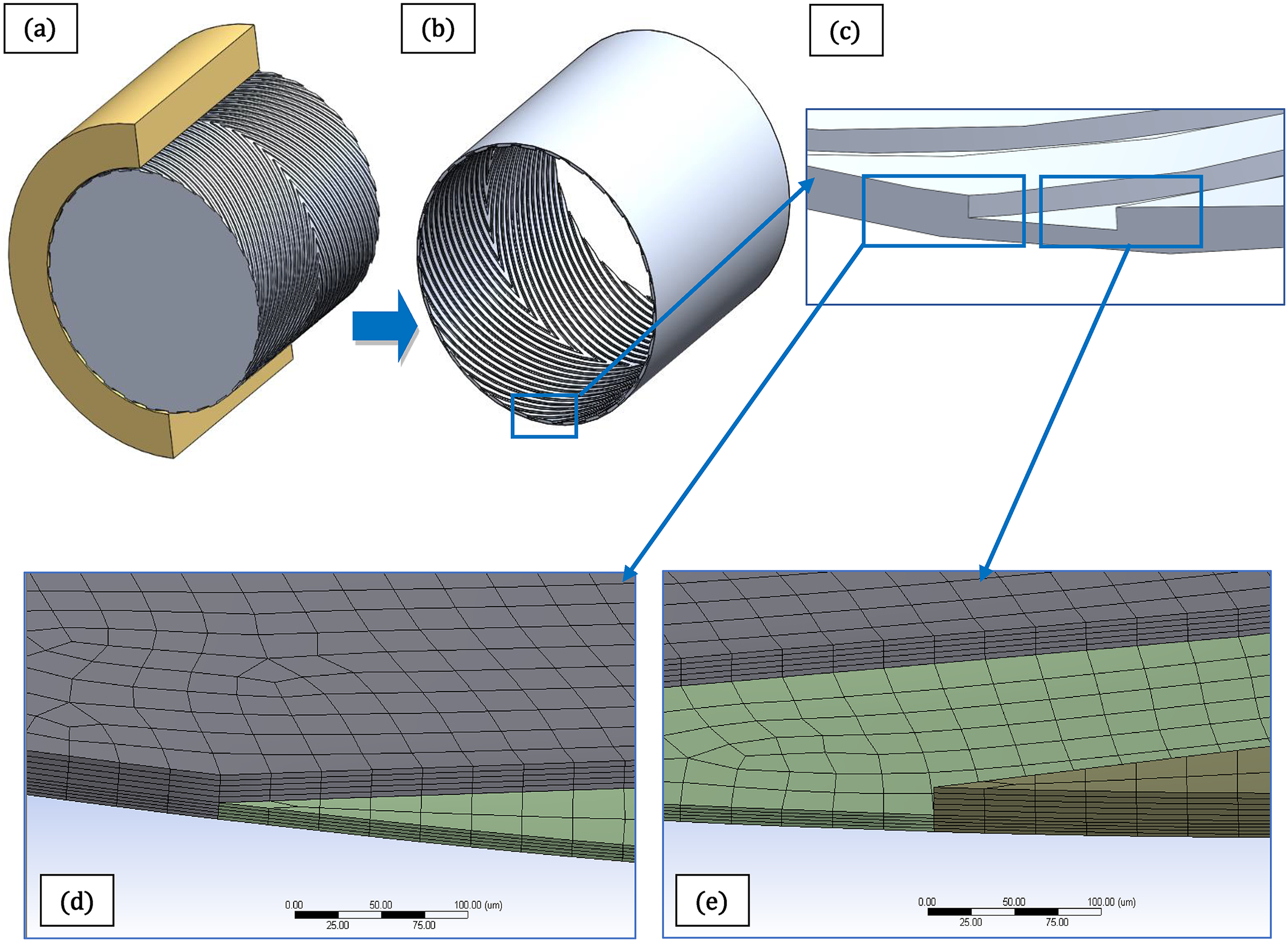
The mesh generated for the FSI simulation (a) the grooves and the sleeve; (b) the air film geometry for the simulation; (c) the larger image of the groove area; (d) the detailed mesh grid of the groove edge; (e) the detailed mesh grid of the groove edge.
FLUENT is used to develop the fluid model. When the mesh grid is imported, it is verified for orthogonal quality and aspect ratio to ensure that the mesh meets the solver's requirements. The Reynolds number of the model is calculated, and the flow is proved to be laminar. The energy equation is activated to enable the material density method to model the compressibility of air. Additionally, the thermal conditions of the domain's surfaces are set to the mixed method to account for both convection and radiation. Because the ambient temperature is usually lower than the temperature of the fluid domain when rotating, the thermal model mostly dissipates heat into the environment. The temperature rise is compared to experimental data to tune the thermal parameters. The simulation is transient and pressure-based, using a 1e-5 s time step.
For the FSI solution, the dynamic meshing function is enabled. The FEM model's computed rotor position change is transferred to the fluid domain via the mapping interfaces. The general grid interface (GGI) mapping algorithm is utilised, which projects the element sectors on both sides to a controlling surface. 22 The GGI mapping is shown in Figure 7.
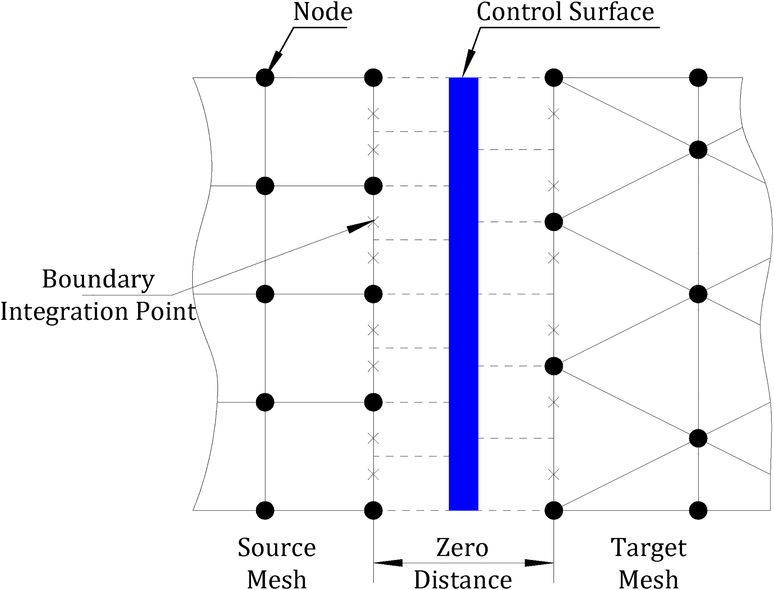
General grid interface mapping.
The FEM model is constructed in APDL, which is integrated into Workbench. Because the FEM mesh nodes do not need to be matched to the fluid model using the GGI mapping, the number of mesh elements is greatly reduced. To account for rotor deformation caused by rotordynamics behaviour, the Coriolis effect, weak spring, and large deflection functions are activated. The direct solver is employed, and the full Newton-Raphson option for nonlinear control is enabled.
Dynamic characteristic coefficients modelling
Stiffness coefficient
The relationship between the variation of hydrodynamic force and the disturbance of the rotor is nonlinear, but when the disturbance is sufficiently small, it can be approximated as linear.
23
When a small perturbation motion is generated around the equilibrium position, the expression for the force on the air film can be expressed as: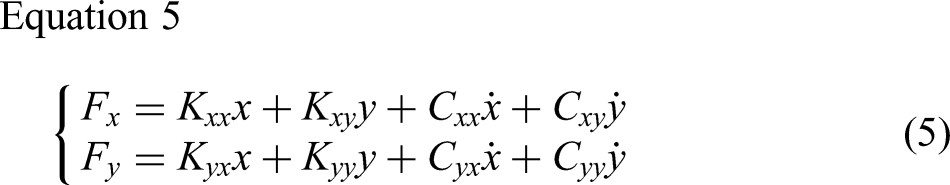
where
Convert Equation 5 to the matrix form as shown in Equation 6.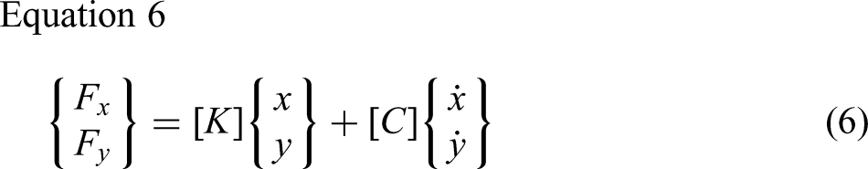
where
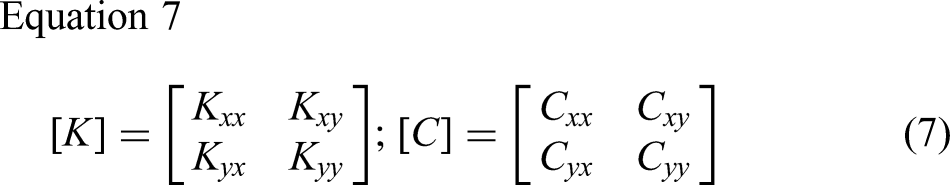
The influence coefficient method is adopted to model the stiffness of the bearing. The force vectors are applied on the bearing respectively to disturb the system. When the rotor reaches the equilibrium position with the constant external load, the values of 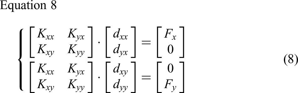
where in
The disturbance force is modelled as a sine wave with varying frequencies to determine the dynamic stiffness coefficient as the function of the excitation frequency. The amplitude of the sine signal is 1N. The disturbing forces are in x and y directions sequentially, and the trajectory of the rotor is monitored to determine the displacement of the rotor. The maximum displacement of the induced trajectory is recorded as the effective displacement
Damping coefficient
Another bearing characteristic that can be explored to verify the proposed model is damping. The damping coefficients are calculated numerically in this study using the harmonic excitation method. Here are two harmonic forces to consider: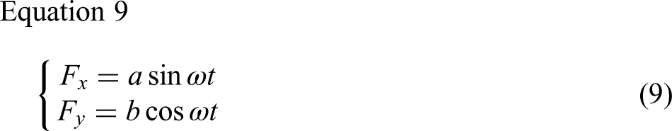
The motion of the rotor caused by the harmonic forces is monitored in the FEM solver. The motion equations are assumed in the following format: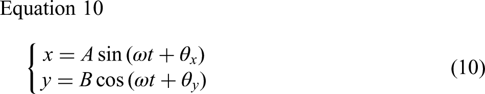
The damping coefficients are obtained by substituting Equation 9 and Equation 10 into Equation 6 and Equation 7: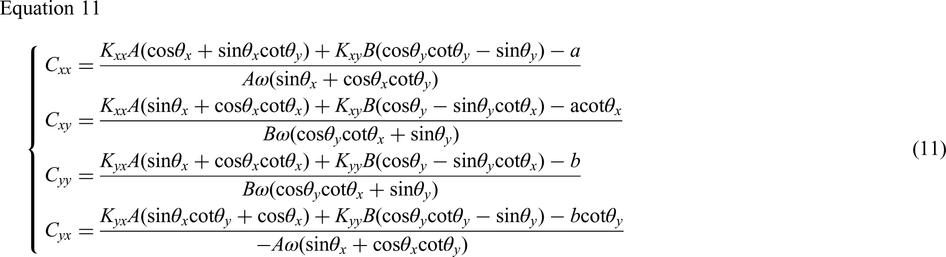
Verification of the model
The simulation results are compared with the experimental results published by Guenat et al., 24 concerning the dynamic characteristics of the HGHJBs to test the accuracy of the proposed model in predicting the dynamic stiffness of the HGHJBs. The basic bearing parameters are the same as the proposed bearing system in Table 1, while the rotor's main parameters are as follows: the rotor's length is 176 mm, and the distance between the centres of the two HGHJBs is 88 mm. The centre location of the rotor features an impulse turbine, while the two ends of the rotor serve as thrust bearings. More details of the test rig used in the experiment can be found in reference. 24
Figure 8 shows the simulation results in comparison with the experimentally determined coefficients at the speed of 100k rpm. 24 Coefficients are shown as a function of the sinusoidal excitation frequency. In the graph, the excitation frequency is divided by the rotating frequency for comparison. The measurement of the groove depth and the air film thickness was carried out at 5 axial locations, the measurement uncertainty was documented in the experimental results. In the model, the parameters related to air film thickness and groove depth are set to the maximum deviation dimensions. The results are shown in Figure 8, the average relative percentage error in the direct stiffness coefficients is 5.81%. When compared to experimental measurements, the simulated cross-coupled stiffness coefficients exhibit a similar trend, but with an average deviation of 0.59 MN/m. The direct stiffness coefficients have better agreement with the experimental data than the cross-coupled stiffness coefficients, while both show good agreement in the trend as frequency increases. Both the direct and cross-coupled damping coefficients agree well with the experimental results. The average deviation of direct damping coefficients is 45.66 Ns/m, whereas the average deviation of cross-coupled damping coefficients is 120.31 Ns/m. Both exhibit the same trend as the experimental data as frequency increases. The above results suggest that the model can be used to compute the dynamic coefficients of the HGHJB.

Verification of the simulation results against the published experimental results: (a) direct stiffness coefficients; (b) cross-coupled stiffness coefficients; (c) direct damping coefficients; (d) cross-coupled damping coefficients.
The reduction of the lift-off speed
The EM force assists in lifting the rotor and is intended to reduce wear by lowering the lift-off speed, which is determined using the FSI method described above. The purpose of the simulation is to determine the lowest speed that will keep the rotor floating. The rotor begins with an eccentricity ratio of 0, and the external factors are gravity, residual imbalance mass, and the turbine's driving torque. The simulations are running in loops, as indicated in Figure 9.
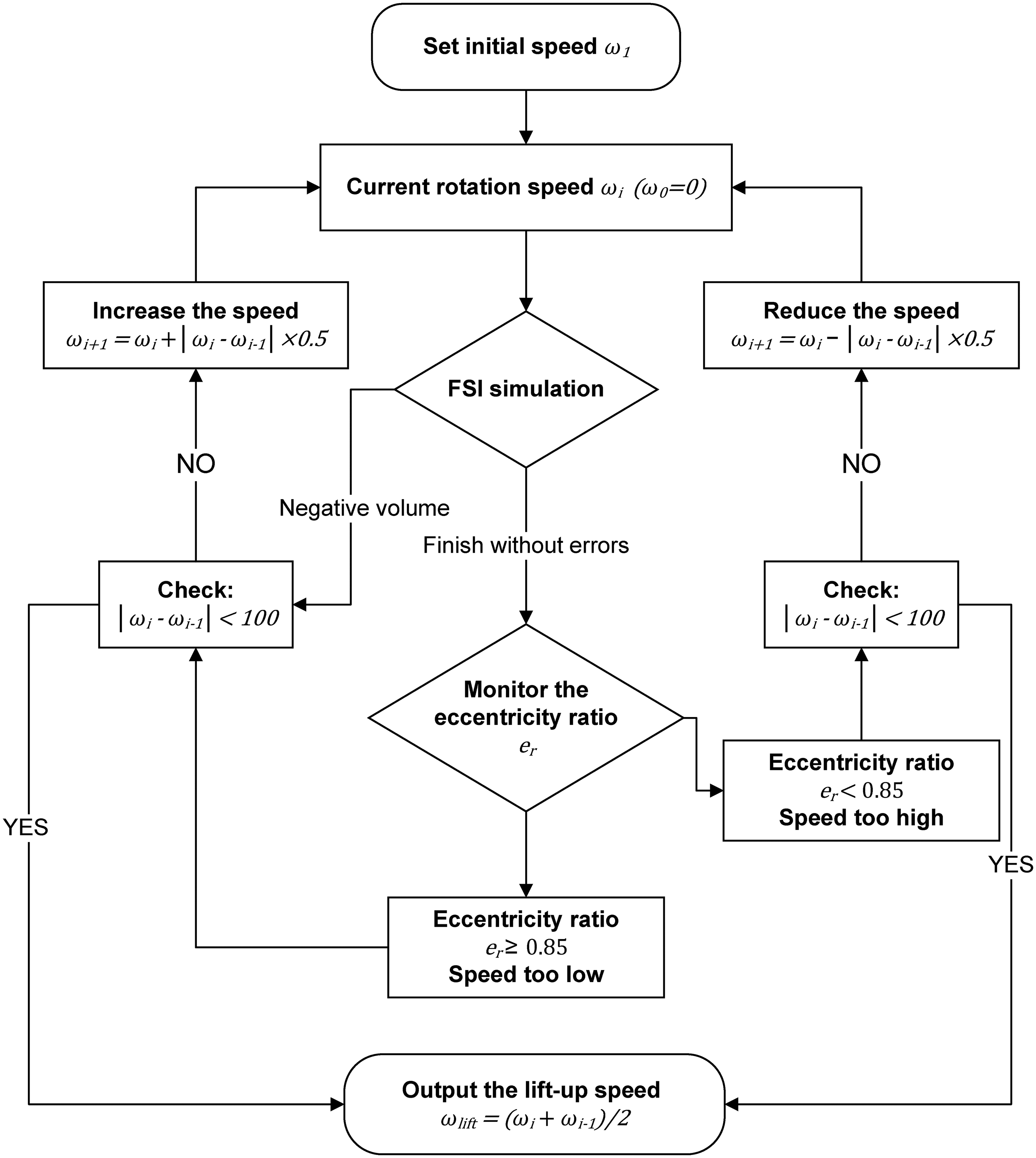
Simulation flow chart for calculating the lift-off speed with the model.
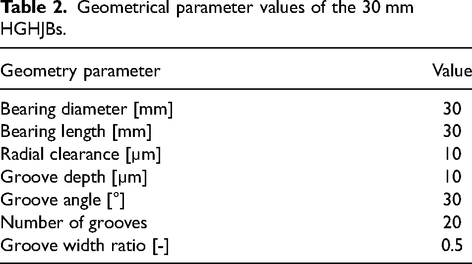
The HGHJB used in the simulation is 30 mm in diameter. The main parameters of the HGHJBs are listed in Table 2. The rotor is made of stainless steel and has a mass of 1.26 kg. The structure of the testing rig is demonstrated in Figure 15 (a), and the simulations were carried out using the same geometry. Each HGHJB features two pairs of grooves that cover 30% of the axial length of the bearing surface beginning at the two axial ends.
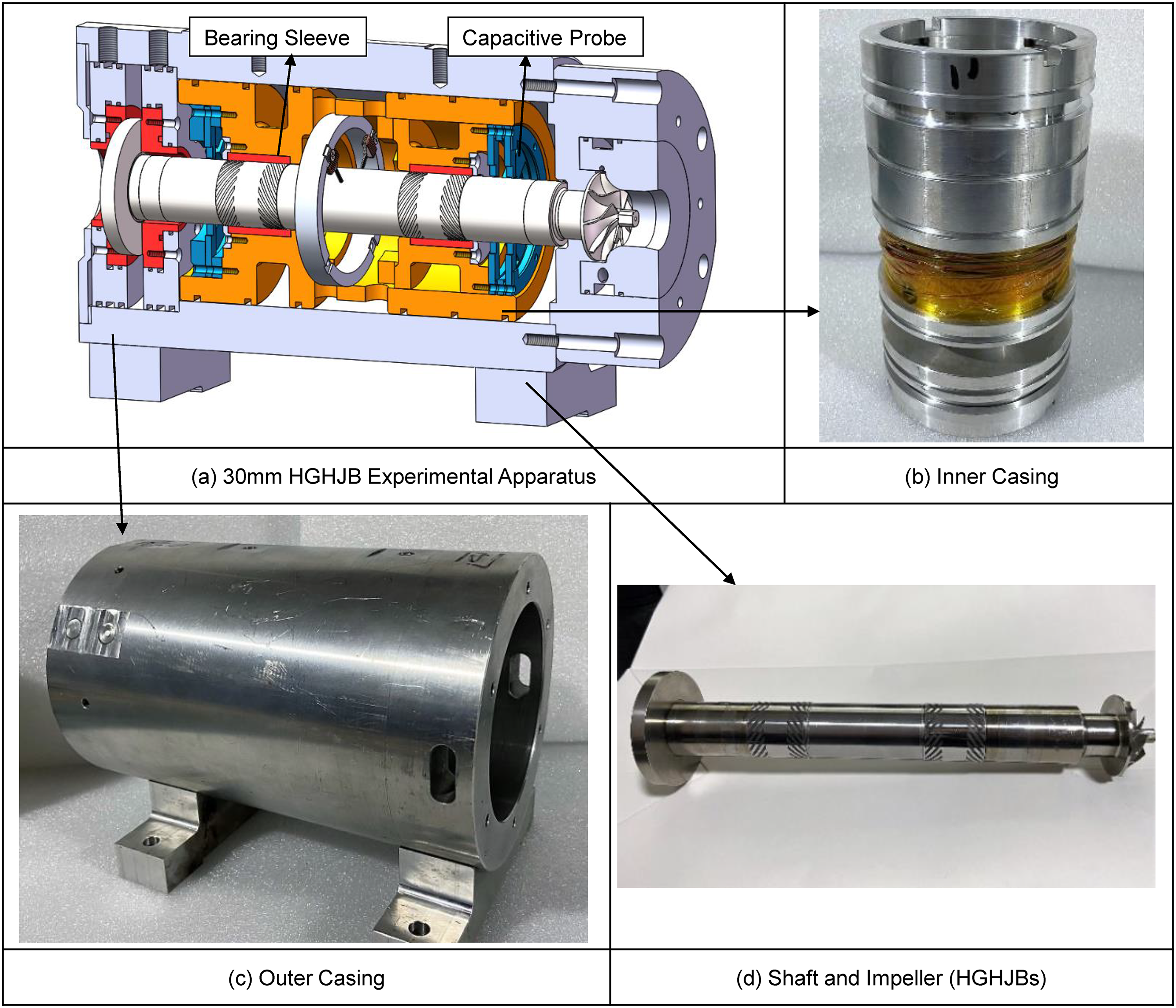
The experimental apparatus of the 30 mm HGHJB rotor. (a) 30 mm HGHJB Experimental Apparatus. (b) Inner Casing. (c) Outer Casing. (d) Shaft and Impeller (HGHJBs).
Geometrical parameter values of the 30 mm HGHJBs.
The simulation model generated a series of rotor orbits to assist in determining whether or not the rotor floats. The criterion for a rotor to be considered floating is an eccentricity ratio of less than 0.85. The orbits of the rotor without the effect of EMs are shown in Figure 10. The initial rotational speed for the simulation was 10,000 rpm, at which point the rotor maintained an orbit with a diameter of 6.12 µm, indicating that 10,000 rpm is higher than the lift-off speed. When the rotating speed was decreased to 5000 rpm, the rotor crashed onto the sleeve as shown in Figure 10(b). The rotational speed was then changed to 7500 rpm, 6250 rpm, 5313 rpm, 5469 rpm and 5391 rpm following the procedures shown in Figure 9 until the range was narrowed down to 100 rpm. The final lift-off speed was determined to be 5430 rpm.
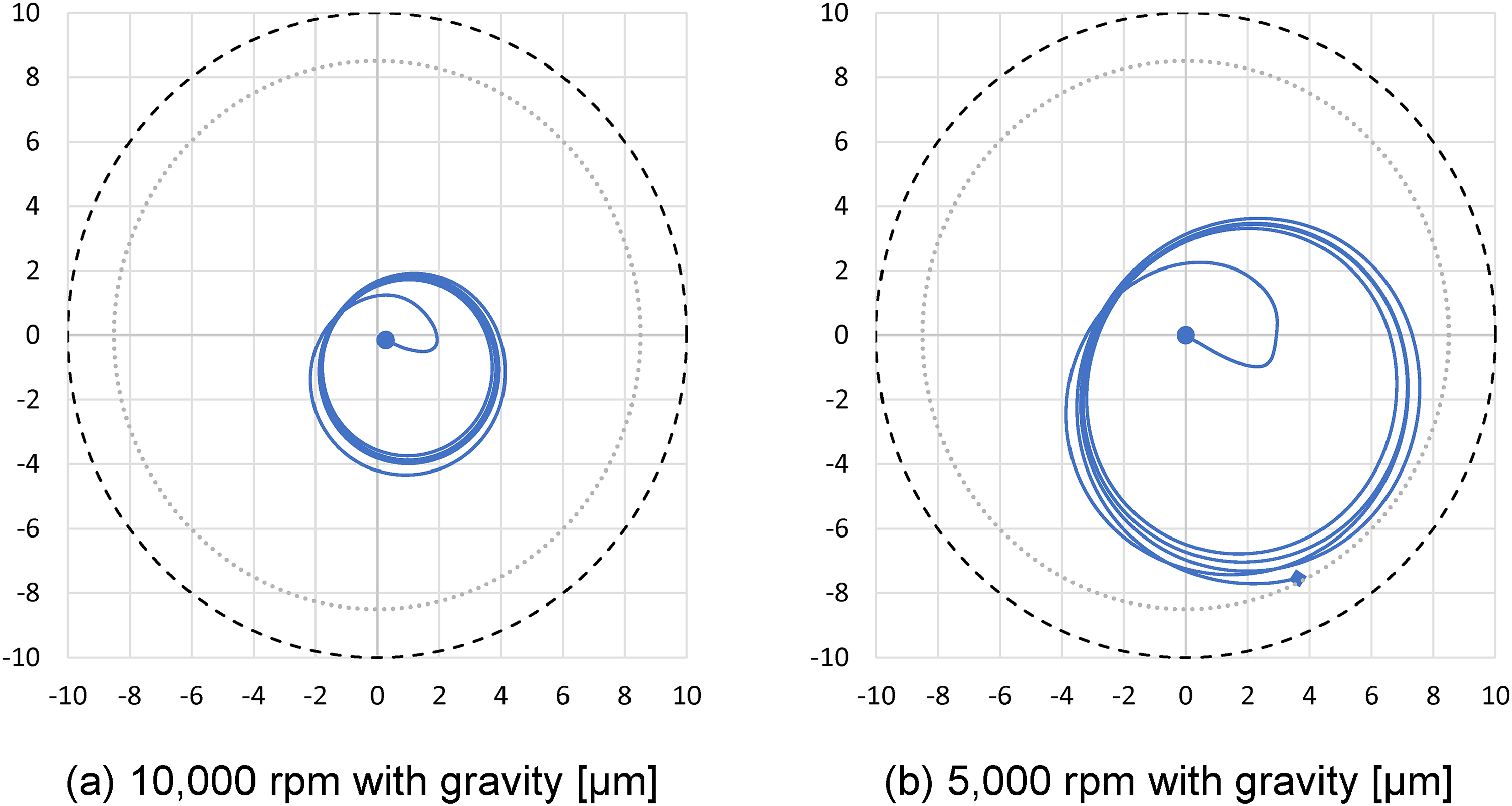
Orbits of the 30 mm HGHJB with gravity. (a) 10,000 rpm orbit; (b) 5000 rpm orbit.
Figure 11 shows the orbits of the rotor at 5000 and 2500 rpm, respectively, when the EM force was applied to counter the gravity. The rotor was only subject to residual unbalance mass and the torque during the acceleration. Following the same approach as the previous simulation, the final lift-off speed was determined to be 2930 rpm. The lift-off speed was reduced by 46.04% compared to the original 5430 rpm.
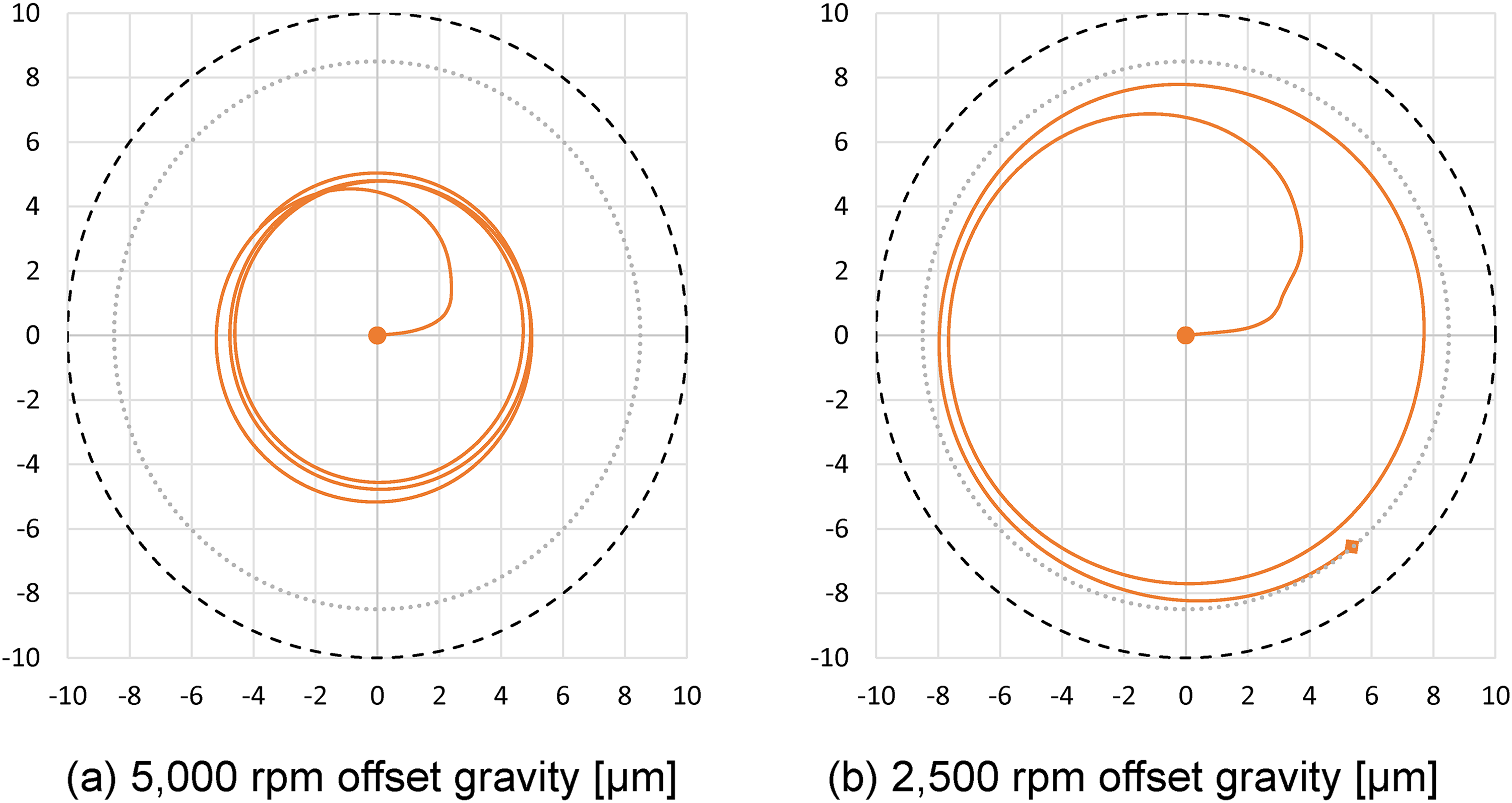
Orbits of the 30 mm HGHJBs offset gravity. (a) 5000 rpm orbit; (b) 2500 rpm orbit.
Design and test of the EMs
Experimental apparatus was developed to conduct tests at ambient temperature and atmospheric pressure. The shape of the EM is designed into a probe shape, and the cross-section of the probe is small. The EM force is designed up to 100 N. Shown in Figure 12 is the conceptual drawing of the EMs and the holder.
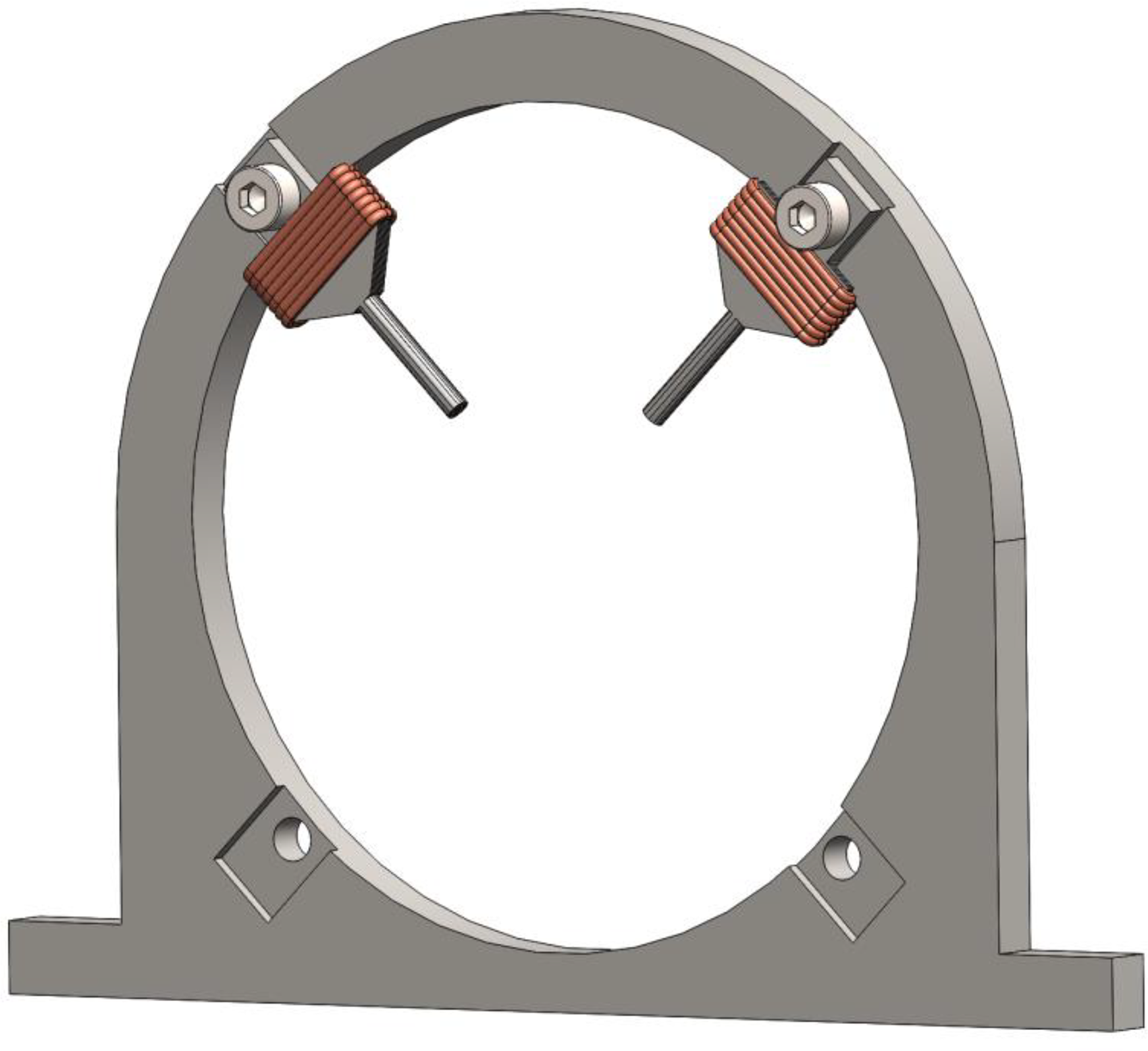
The conceptual design of the EMs and the holder.
A direct current power unit controls the EMs. The experiment setup depicted in Figure 13 is created to calibrate the magnetic force acting on the shaft. The shaft is held in place by two force sensors with shaft holders affixed to the top. The positions of the force sensors can be adjusted vertically and horizontally. The horizontal direction adjustment of the holder allows the change in the radial clearance between the shaft and the EMs. The rotor used in the experiment is a dummy rotor with the same material, weight, and diameter as the real rotor, but without the grooves.
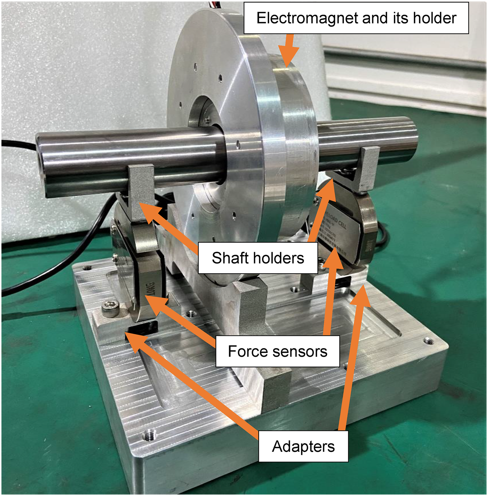
Test bench of the Ems.
In the tests, the combined EM force was applied in the same direction as gravity to test the EMs. The force sensors directly support the rotor, preventing relative movement between the EM and the rotor and maintaining the 500 µm clearance. As shown in Figure 14, when no current is applied, the gravity of the rotor is 13.3 N. When a current of 2.5 A was applied, an EM force of 13 N was generated equal to the gravity of the rotor to counter the shaft's gravity. Additionally, by delivering a 4.5 A current to the EMs, a maximum EM force of 77 N can be achieved.
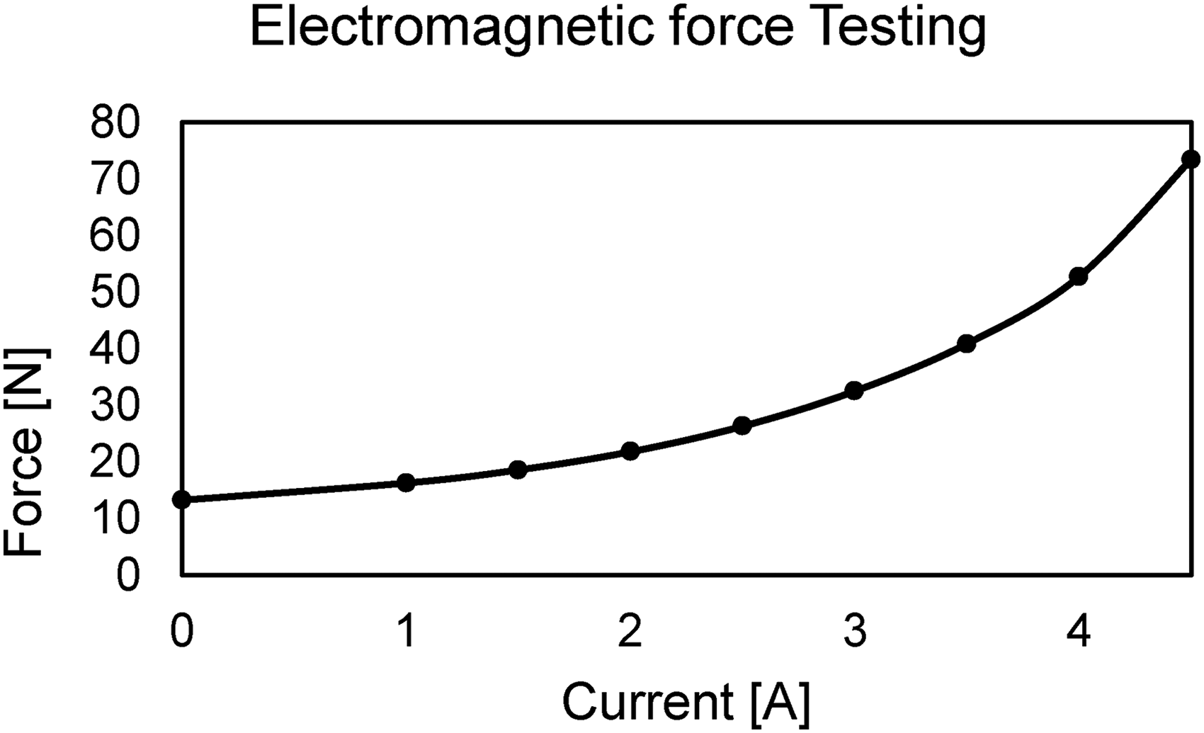
Em force testing result.
Experiments and discussions
The test rig is constructed in order to determine the lift-off speeds. Figure 15 outlines the main components and structure. There is a hydrostatic air thrust bearing and two HGHJBs supporting the rotor. The rotor is driven via a turbine by compressed air. The inner and outer casings are made of aluminium alloy and the bearing sleeves are made of stainless steel with DLC coating. The EMs are positioned around the axial middle of the rotor to provide lifting forces.
In the experiments, the lift-off of the rotor was monitored by the capacitive probes located near the HGHJBs. The EMs were activated prior to the rotor being driven by compressed air in each experiment. 2.5 A current supplied to the EMs was found to be the upper limit, as it would attract the rotor to the bearing sleeve. The lift-off speeds were monitored in both acceleration and coast-down processes, and the results were documented.
Experiments were carried out a total of ten times, with the results given in Figure 16. The average lift-off speed during acceleration is reduced from 6156.9 rpm to 3308.4 rpm with the EMs activated, a drop of 46.27% is achieved. Similarly, the average lift-off speed is reduced by 48.39% during coast-down from 5826.7 rpm to 3007.1 rpm. Compared to the 46.04% reduction computed by the FSI model, the difference is very small. When examining the percentage reduction in lift-off speed, the experiments and simulation model are in good agreement.

The experimental results of the lift-off speed of the 30 mm rotor. (a) 30 mm HGHJB testing with gravity. (b) 30 mm HGHJB testing offset gravity.
The average lift-off speed during acceleration is 6156.9 rpm without the EMs, which is 13.39% higher than the simulation results, and the average lift-off speed during coast-down is 5826.7 rpm, which is 7.31% higher than the simulation results. The average lift-off speeds in the acceleration and coast-down processes when the EMs are activated to counter gravity are 3308.4 rpm and 3007.1 rpm, respectively, which are 12.9% and 2.6% higher than the simulation results.
The discrepancies of the simulated and the experimental results range from 2.6% to 13.39%. There are a few possible explanations for the differences. There is some variation in the groove depth, but it is not considered in the simulation. With laser cutting precision errors, performance degradation in comparison to ideal groove geometry is unavoidable. Additionally, the surface conditions of the simulation and practical components are different, resulting in the simulation model being overestimated. However, the 46.04% drop in lift-off speed shown by the simulated percentage reduction is quite close to the experimental result. The lift-off speeds are almost equally overestimated in both conditions, resulting in a percentage improvement that maintains good accuracy. Overall, the modelling results agree with the experimental data.
Compensation for the loss of HGHJB performance
The HGHJB's performance may be compromised by the changes in atmospheric pressure, temperature, and viscosity. However, it is possible for the compromise to be compensated and enable machines with HGHJB to operate reliably in a variety of conditions, including high altitudes.
A study was carried out based on an operating environment of 4000 m above sea level in comparison with the performance at sea level. 4000 m altitude is the environment of Tibetan plateau, Pamir plateau and low-altitude flights. At such a level, the viscosity of the air decreases, resulting in the change of stiffness of the bearings. Such a change may result in a shift in the critical speeds, which may pose a threat to high-speed rotors due to their narrow safe operation speed range. EMs can be utilised to adjust the performance of HGHJB by altering the rotor's eccentricity ratios to keep the rotation stable.
A new test model was constructed with the rotor in the vertical position and the thrust bearing carrying gravity; the HGHJBs operate in a steady state with a constant rotational speed. The EM forces were applied in the x-direction as shown in Figure 17.
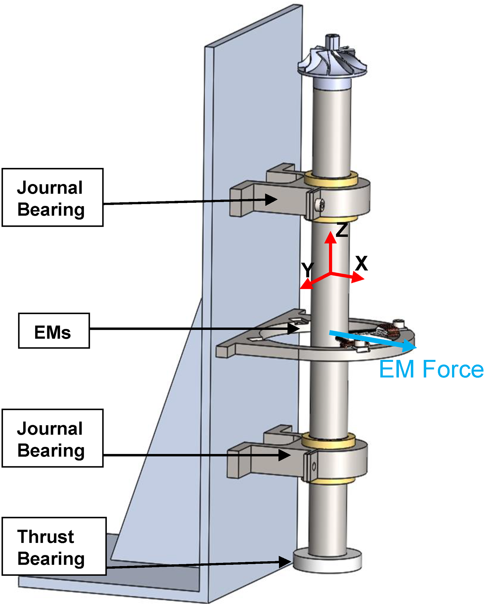
The schematic diagram of the vertical rotor orientation.
The simulation started by setting the rotor speed at 80,000 rpm, the temperature at 23°C, and the atmospheric pressure at 1 ATM to reflect the working environment at sea level. Then, the 4000 m condition was simulated using a reduced temperature of −10.98 °C and a reduced atmosphere pressure of 0.6166 ATM. The result indicates that the shaft operates at an eccentricity ratio of 0.03, which provided sufficient space for the EM to drag the rotor to a high eccentricity ratio. Then 9N, 18N, and 20N EM forces were applied to the rotor, and the stiffness coefficients were determined using the same simulation method.
The stiffness coefficients are studied in this case study. Due to the limited damping capability of the air film, 21 the HGHJB system requires an external damping structure to help stabilise the vibration. Considering the system's rotordynamics design, the stiffness produced by the HGHJB has a significant effect on the critical speeds, which cannot be compensated by external components. The results reported in Table 3 shows that both the direct and cross-coupled stiffness coefficients had dropped when the altitude increased from 0 to 4000 m. The direct stiffness coefficients dropped to 72.9% and the cross-coupled stiffness coefficients dropped to 52.9%. The decrease in direct stiffness coefficients is regarded as a performance loss, as they provide rotor lift and have a significant effect on critical speeds. The changes to bearing characteristics may cause the rotordynamics behaviour to deviate significantly from that achieved on the ground, and this could result in potential risks.
80k rpm HGHJBs stiffness coefficients.
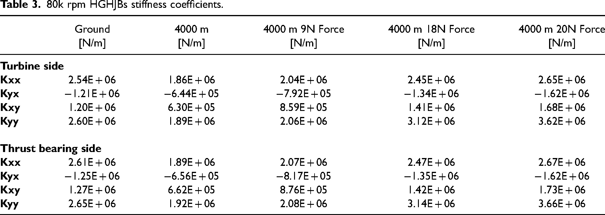
The results show that with a 9 N force, the direct stiffness coefficients recovered by 79.8% of their initial value at the ground, whereas the cross-coupled stiffness coefficients recovered by 68.5%. When the EM force is increased to 18N, the stiffness coefficients increase further; Kxx recovers to 96.5% of its initial value, Kyy exceeds 20.0% of the ground condition, and the average of the cross-coupled stiffness coefficients exceeds 13.7% of the ground condition. At 20N, the Kxx and Kyy are 4.3% and 39.23% greater than the original ground condition, respectively, and the average of the cross-coupled stiffness coefficients exceeds 36.9% of the original ground condition. It can be stated that the EMs considerably improve the performance of the HGHJBs.
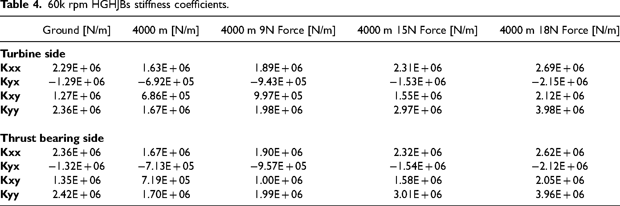
Similarly, simulations were performed at 60,000 rpm for the same circumstances. The results are summarised in Table 4. It shows that a 15 N force may completely compensate for the performance loss. In conclusion, the results prove that the EM compensates for the loss of stiffness coefficients at an altitude of 4000 m.
60k rpm HGHJBs stiffness coefficients.
Conclusions
A hydrodynamic air bearing assisted by the EMs is analysed. The performance was investigated using numerical simulation, and the results were compared with experimental ones. The research reveals that the system is capable of reducing the lift-off speed and adjusting the bearing characteristics. When the shaft is placed horizontally, the EMs can counteract gravity and reduce bearing wear during start/stops. The study finds that the lift-off speed is effectively reduced by 46.04% of the original. Furthermore, the dynamic stiffness was tuned with the EMs to compensate for performance loss due to the reduction in atmospheric pressure and air density. An EM assisted test rig has been built, and the control of the EM forces have been calibrated and verified in experiments.
Footnotes
Acknowledgements
This research was jointly funded by Innovate UK grant 104021 and Department for Transport UK T-TRIG 2019 Scheme. The authors are grateful for the support of Birmingham High Performance Turbomachinery Limited and Liyang Fospova High-speed Machinery Limited.
Declaration of Conflicting Interests
The author(s) declared no potential conflicts of interest with respect to the research, authorship, and/or publication of this article.
Funding
The author(s) disclosed receipt of the following financial support for the research, authorship, and/or publication of this article: This work was supported by the Department for Trasport UK, Innovate UK, Birmingham High Perfromance Turbomachinery, (grant number T-TRIG 2019, 104021).