
Abstract
Disc brakes wear during braking events and release airborne particulates. These particle emissions are currently one of the highest contributors to non-exhaust particle emissions and introduce health hazards as well as environmental contamination. To reduce this problem, wear and corrosion-resistant disc coatings have been implemented on grey cast iron brake disc rotors by using various deposition techniques such as thermal spraying and overlay welding. High thermal gradients during braking introduce risks of flaking off and cracking of thermally sprayed coatings with adhesive bonding to the substrate. Overlay welding by laser cladding offers metallurgical bonding of the coating to the substrate and other benefits that motivate laser cladding as a candidate for the coating of the grey cast iron brake discs. This study aims to investigate the effect of laser cladding on the thermal and thermo-structural performance of the coated grey cast iron brake discs. Therefore, thermal and thermo-stress analysis with COMSOL Multiphysics 5.6 software is performed on braking events of grey cast iron brake discs as non-coated – reference and laser cladding coated with stainless steel welding consumables. The Results demonstrated that surface temperatures were more localised, overall higher in the laser cladded coating with over three times the stresses attained of reference grey cast iron discs. The output of the simulations has been compared by tests found in the literature. Laser cladding presented higher reliability and braking performance, nonetheless requiring the evaluation of its thermal impact on other system components.
Introduction
Braking systems aim to controllably reduce the velocity of a body in motion, or completely stop it. In the case of vehicles, braking is constituted by a torque applied in the opposite direction to a wheel’s motion. This is done so through frictional contact in the tribological pad–disc interface, where a brake pad made of friction material applies pressure on the brake rotor surface. The kinetic energy is then transformed into thermal energy due to friction which, therefore, decelerates the vehicle. The dilemma which accompanies a braking action is, however, the consequence of particle emission. In the debris of worn material surfaces, particulate matter (PM) in the micrometre scale becomes airborne, 1 introducing a severe contamination hazard in urban environments known as non-exhaust emission (NEE). 2 These PMs originate in tyre wear, road surface wear, road dust resuspension and finally, brake pad and brake disc wear. 1
Air pollution has received an extensive focus throughout the last few decades from the European Union and the World Health Organisation (WHO). Much of the work has, however, been inclined towards ‘exhaust’ emissions instead, with hardly any legislation implemented for NEE. 2 This has left NEE with very little development, letting it contribute enough to reach almost half of road vehicle full-scale emissions. 1 As more sustainable vehicles are released on the market such as hybrid or electric cars, the dominating impact gradually begins to shift to NEE. In order to mitigate the issue of airborne PM, many techniques have been implemented. These include hardening, high-velocity oxygen fuel 3 or high-velocity air fuel for thermal sprays, powder welding, atmospheric plasma or flame spraying. 4 All of these offer a range of material deposition on substrates along with different forms of bonding techniques. Nevertheless, challenges, such as crack formations and flaking of coated layers, have demonstrated to occur during braking events. 3
Among other coating technologies, laser cladding (LC; also known as laser metal deposition) by using metal powder welding consumables offers metallurgical bonding of the coating to the substrate, high purity of coating, very low porosity level
5
and quite small thermal deformations of the substrate. It has been proven through pin-on-disc wear testing comparisons with a grey cast iron (GCI) disc that an LC Ni/carbide coating mass wear is halved, specific wear loss is quartered while there was no ‘substantial increase’ in wear from the pin neither.
6
Further, 30% of particle emission concentration is reduced, with an approximate half in ‘size partition of particles below
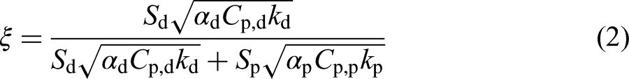
Thermal stress performance highly governs the compatibility and adhesion strength of coatings. Crack formations and flaking are consequences of thermal stresses, which surpass the coating adhesion bonding strength to the substrate. 5 A degree of expansion results from the increase in temperature of a rotor subject to braking conditions. When a rotor is non-homogeneous (as in the case of coatings), thermal expansion differences mean high thermal stresses are developed at the materials interface. 7 Consequently, the coating adhesion with the substrate is at risk of failure.
Various simulation techniques have been implemented in previous studies to predict thermal and stress performances of disc brakes. The variation in these methods is mainly governed by the scale of the analysis. This is relevant for example, on the mesoscopic scale, where a cellular automation approach developed by Müller and Ostermeyer 8 was used to predict plateau dynamics. The literature demonstrates that the effect of mesoscopic contact on macroscopic scales can be simulated numerically with time and length orders of magnitude specified by Wahlström. 9 As this study conducts a physics coupling finite-element analysis (FEA), it is also interesting to refer to Pan and Cai, 10 who demonstrate that heat flux due to friction can be translated into an area subject to a direct heat rate. The literature gap however lays in the fact that no research has been done to simulate the above-mentioned mechanical performance relevant to coated disc models.
The aim of the present work is to investigate the effect of LC coating of GCI brake disc rotors on the discs’ thermal and thermo-structural performance. This is done by simulation of the braking event for reference GCI – and LC-coated rotors by using COMSOL Multiphysics 5.6 simulation software. Regarding thermal stresses, this is highly relevant for the evaluation of predicted LC compatibilities under braking conditions. Stress magnitudes can be anticipated before the deposition process takes place, in order to establish a degree of bonding tolerance.
Method
In the present work, an FEA study was conducted to simulate a dyno bench test environment. This allowed for the validation process of the model, which represented a conventional uncoated (or homogeneous) GCI brake disc, simulated under the same conditions as the dyno performed by Wahlström. 9 A laser cladded coating was added to the same model subject to simulation, in order to identify clear comparisons. A physics coupling interface software was used in order to combine both heat transfers in solids with solid mechanics hence, able to obtain thermal stress data. These are obtained by firstly importing a computed temperature field model. 10 This is obtained through an FEA study performed by the implementation of a heat source, representing a frictional heat flux. The thermal implementation is specified as a region where the inward heat flux is directly acting, as opposed to specifying the sweeping commands of a frictional heat source. 11 Thermal data is then, automatically fed back into the study through a coupled software interface to compute thermal stress values.
The applied pressure on the rotor in the dyno test is a known parameter, which by multiplying by the pad contact area, determines the normal force applied. The need for calculating the inertial load received by the front vehicle axle dependent on its deceleration is therefore eliminated.
9
This facilitates the computation greatly given that only one simple expression must be specified. If we begin by stating the braking power as stated in equation (1)
10
that the disc receives


Simulation specimens and materials
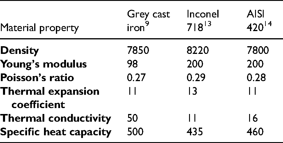
The proposed coating application consists of a nickel-based alloy buffer layer, with a martensitic stainless steel overlayer. These are deposited on a GCI substrate as the core material of the brake disc. Regarding material data, an approximation is made with a nickel-based alloy type Inconel 718, 13 and martensitic stainless steel type AISI 420. 14
Martensitic stainless steels in general offer relatively high hardness, moderate to high wear resistance and moderate to good corrosion resistance. 14 The function of the interface layer is twofold to act as a corrosion barrier by sealing the GCI rotor from potentially infiltrated moisture and other corrosive agents, and to prevent dilution of graphite from the substrate material with the martensitic stainless steel surface coat. This dilution would occur during LC of the martensitic steel overlay over bare GCI surface and substantially lower the quality of the cladding. However, by having a nickel-based alloy buffer layer with virtually no chemical affinity to carbon as opposed to martensitic stainless steel, the dilution is suppressed. Lower heat infiltration into the disc core is also achieved given that this interface layer acts as a thermal barrier that traps most of the heat at the surface of the coating. Following in Table 1 are the listed parameters representing relevant material properties implemented in the study.
Material properties for rotor sections. Grey cast iron, Inconel 718 and AISI 420 refer to the disc substrate, interlayer and overlayer respectively.
Implementation
The chosen FEA software is COMSOL Multiphysics 5.6. Other than its simplicity of use and the straightforwardness of configuration commands, the software provides the possibility of coupling different physics that are needed to be analysed, through a Multiphysics command. The benefit of this option associated with this study is the analysis of both heat generation in a disc brake rotor and its associated thermal stresses. Downsides include computational cost, which is why it is crucial to retail a simplified model 15 for mesh independence. Figure 1 displays the simulation routine implemented in the study.
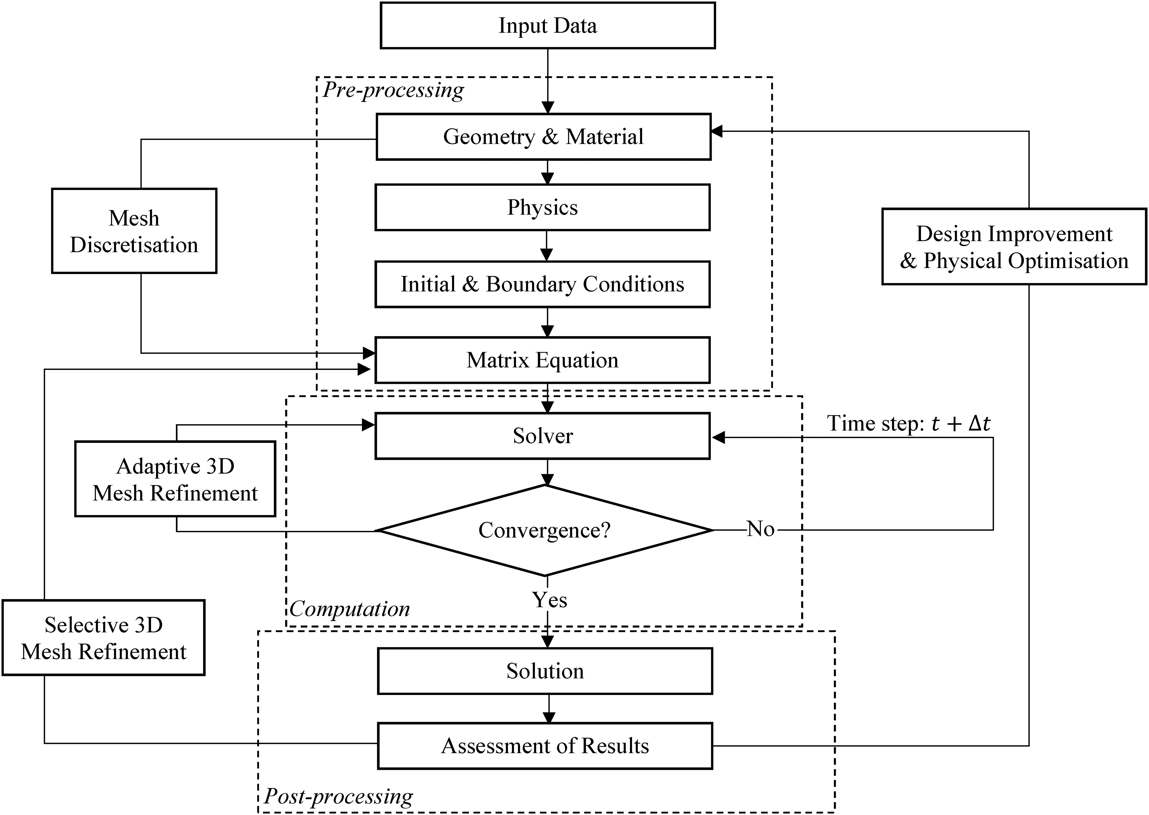
Overview of simulation routine.
Each routine was repeated for each model: GCI and LC. These consist of an identical geometry distinguished purely by the two
Furthermore, a
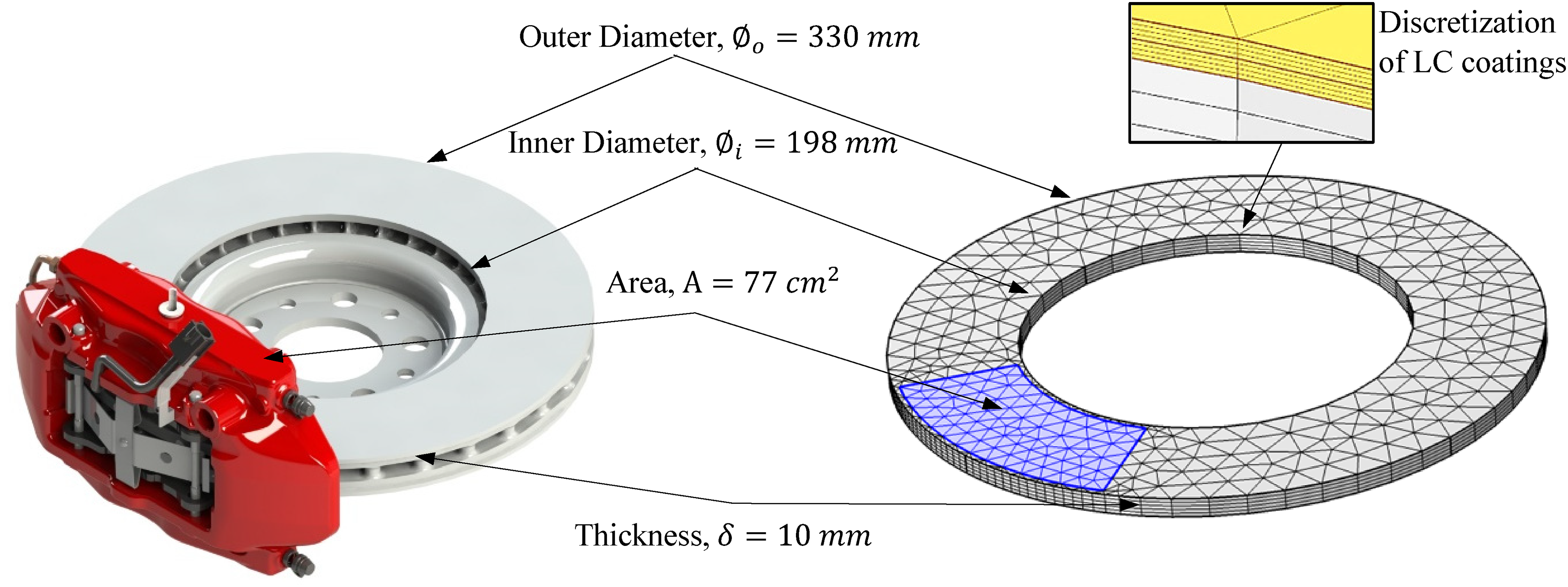
Disc brake assembly rendered on SolidWorks (left), finite-element analysis (FEA) disc model designed on COMSOL (right).
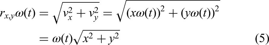
Each domain (bulk, interface and surface layer) is specified with its according material properties as specified in Table 1. The translational motion is specified as a local disc velocity vector 

An adaptive mesh refinement iteration is made of 11 sequences, where the computation is physics controlled. As well as this for post-processing, a selective mesh refinement is made to obtain mesh independence in the required regions of interest. Finer meshing is implemented in regions of high expected thermomechanical gradients, hence in the influx boundary region of frictional heat, 10 highlighted on the meshed model in Figure 2. Mesh refinement validation is achieved in three different regions of the model: the pad-to-disc contact, the region of circular sweep path of the pad and the disc thickness. The absolute percentage difference is brought down to <1% for each model, with every decrease in element size. Computational cost is hence minimised in exchange for the required accuracy of results. 11 A triangular mesh is established at the surface of the disc of the same fineness for both GCI and LC. Triangular elements are used given that results prove to follow experimental data with more comparable synchrony and magnitudes, as opposed to quadrilateral elements. 15 The thickness of the disc is swept and distributed between initially, an equally sized number of elements as shown right of Figure 2 (a zoomed-in section of the LC discretised coating is displayed). It was however found that by setting a predefined symmetric elemental growth where element separations decrease as boundary domains are approached, mesh independence was achieved more effectively. The number of elements is varied until mesh independent results are observed throughout the LC interior. An element ratio of 20 is set in each coating thickness distributed between 20 elements symmetrically. The GCI substrate is set to an element ratio of 100, where element separations decrease towards the interlayer and distributed between 40 elements. This configuration was found to optimise validation of the model, at the appropriate computational cost.
Hence, the combination of a 2D mesh (as triangular elements) with swept elements (along the disc thickness) instead of directly implementing 3D (tetrahedral) elements
15
provides the following benefits: reduces mesh detail where it is not required and provides adjustable interior accuracy of the model. This plays a significant role especially for the LC simulation due to its fine surface geometry of the coating layers and delicate interface regions. Computational cost of the LC simulation is hence greatly reduced given that a 3D element geometry would significantly increase the total number of elements needed to fully discretise the model. The computation is run for time increments of
Results
The first part displayed in this section presents the verification of temperature evolution and thermal stress evolution by comparison with results found in the literature. The second part presents thermal comparisons in the form of graphs as well as 3D temperature maps, followed by thermal stress comparisons also in the form of graphs and 3D thermal stress maps at LC coating interfaces.
Comparison with literature results
Physics validation was made with Pan and Cai's
10
measured stresses from a dynamometer by recreating the described model with the provided parameters. These consisted of a disc outer radius,
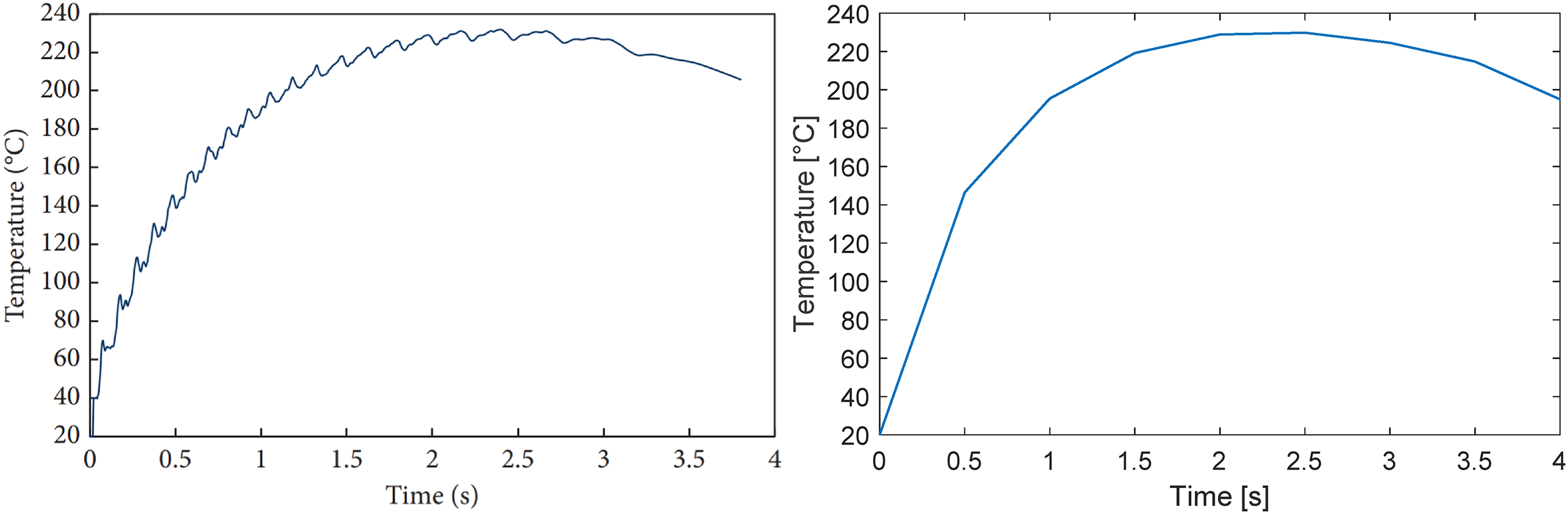
Temperature verification: Experimental temperature evolution retrieved from Pan and Cai 10 (left), re-modelled COMSOL simulation (right).
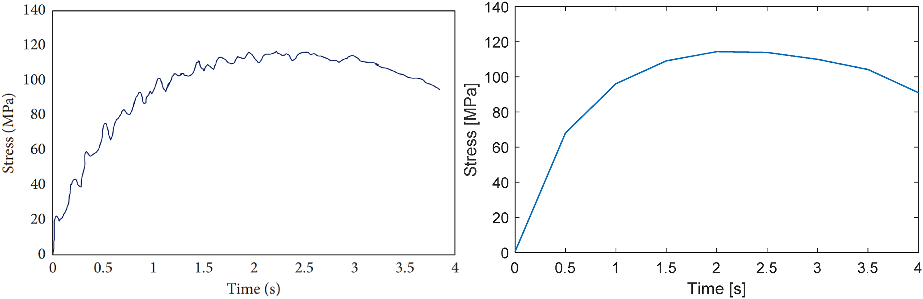
Thermal stress verification: Experimental thermal stress evolution retrieved from Pan and Cai 10 (left), re-modelled COMSOL simulation (right).
Results therefore demonstrate of being in line with literature data. This allows for verification of the GCI model, given that results from the literature are obtained from a GCI disc brake rotor. The selective mesh refinement was followed for a temperature evolution along a line at the effective radius travelling all the way through the thickness of the disc. The effective radius is determined as the centre of mass (or nominal contact pressure) of the pad appliance onto the disc. The thickness of the disc was distributed with the above-mentioned mesh combination. The displayed temperature variation is selected at a time instant of
Thermal analysis
The following plots display the heat evolution along the thickness line positioned vertically at the effective radius of the disc. This may be considered the disc thickness. The purpose of these results is beginning to evaluate how much heat is infiltrated into the disc and consequently, conserved in the LC coating. This data will then be fed back into the simulator to solve for solid mechanics of the model, in order to determine thermal stresses.
It is important here to take into account that these above plots from Figure 5 are the converged plots obtained from the iteration sequences previously performed for mesh independence. The plot for LC extends further due to the
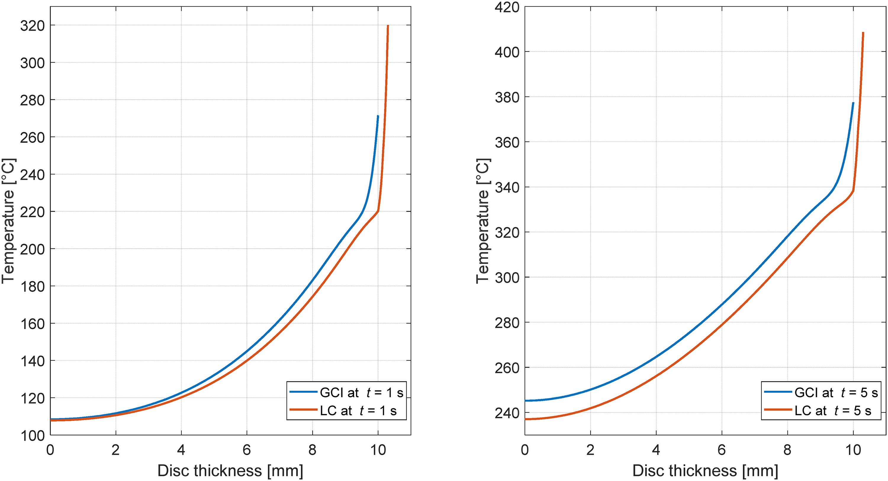
Temperature evolution along the disc thickness line. GCI and LC are presented after 1 s of braking (left) and after 5 s of braking (right).
On the other hand, right of Figure 5 is the thermal distribution at the instant of 5 s, therefore still within braking conditions. Peak temperatures reach
Following is a series of stretched volume plots in Figure 6, which are cut at their quarter sections to display the evolving temperature map across their surfaces as well as their interiors. Each column corresponds to time instants of 0.1, 1 and 5 s of braking, and are governed by the same temperature map as indicated in their legends, for clear comparison purposes between GCI (top row) and LC (bottom row). Due to the vertical deformation of the models, for LC (bottom row), the two coating layers can be observed outlined around the top of the disc.
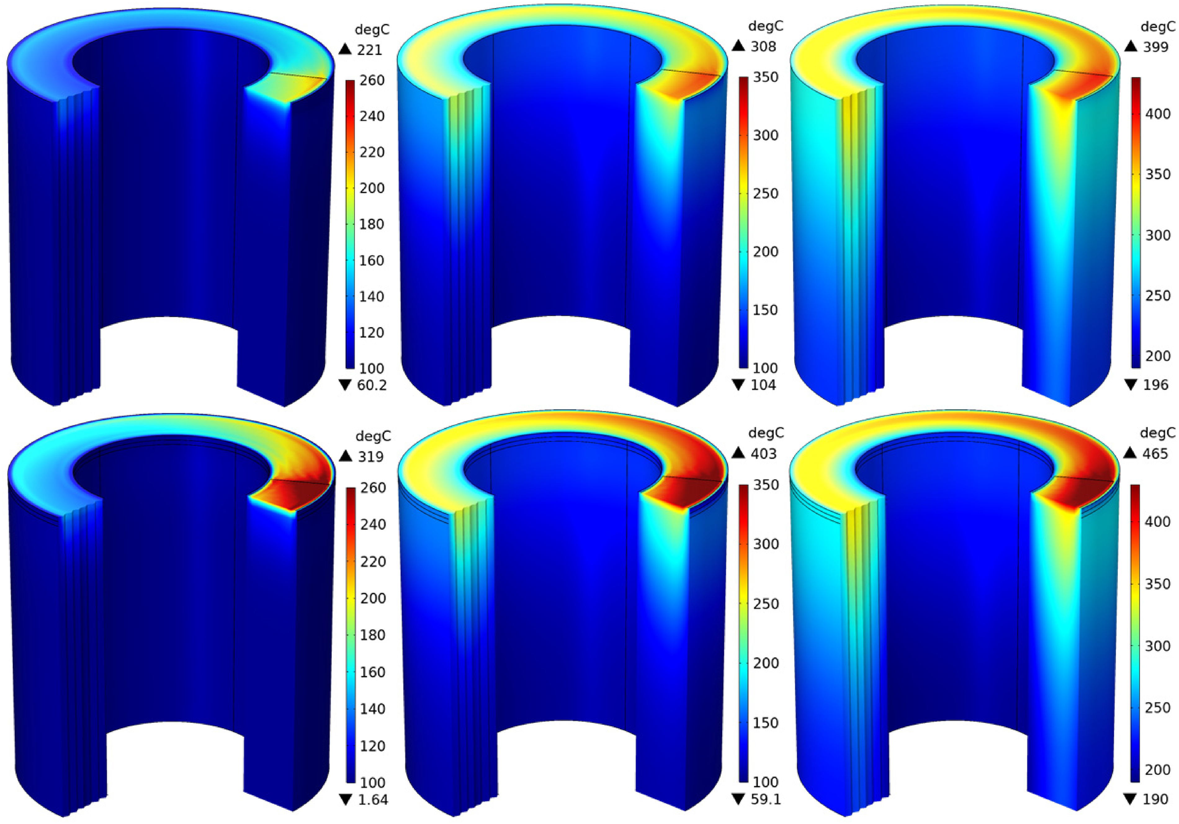
Cross-sectional displays of temperature contour maps for GCI (top row) and LC (bottom row). Time instances are 0.1, 1 and 5 s of braking, corresponding to each column, respectively. Legend units:
Results demonstrate of being in line with literature data.
9
–
11
It can be observed that higher temperatures are attained in the LC coating as opposed to the GCI surface. As expected, differences in material properties of each model constitute clear divergences in thermal behaviour. Thermal conductivity of GCI (


Stress analysis
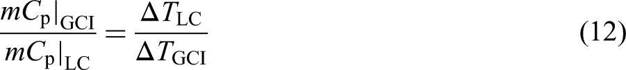
Figure 7, which displays the stress evolution along the thickness line, demonstrates a range of stresses distinguished between each model. Right of Figure 7 is the zoomed-in view where the coating sections can be identified from the horizontal axis.
Thermal stress evolution along the disc thickness line for GCI and LC, after 5 s of braking. The full disc thickness is displayed on the x-axis (left). The zoomed in LC coating thickness only, is displayed on the x-axis (right). Looking at ‘Coating thickness’ (right), interface of GCI substrate to Inconel 718 interlayer occurs at
The above plots from Figure 7 are obtained owing to computed temperature data previously displayed in Figures 5 and 6. These are plotted at a time instant of 5 s within a braking cycle, hence approaching maximum attained temperatures. Left of Figure 7 is the full disc thickness with corresponding thermal stress values along it. Visibly, substantial stresses are developed at a thickness of
Looking right of Figure 7, the LC coating thickness is displayed with zoomed-in peak data to clearly observe thermal stresses. The first LC peak (substrate to Inconel 718 interface) is at
Following are a sequence of stretched volume cut displays in Figure 8 for LC. These are cut at their half sections to observe development of stresses zoomed-in at the laser cladded layer interfaces. The sequence is taken for time instances of 0.1, 1, 3, 5, 6 and 10 s, respectively. Each of these hold a different colour range corresponding to the appropriate stress distribution map at that period in time.
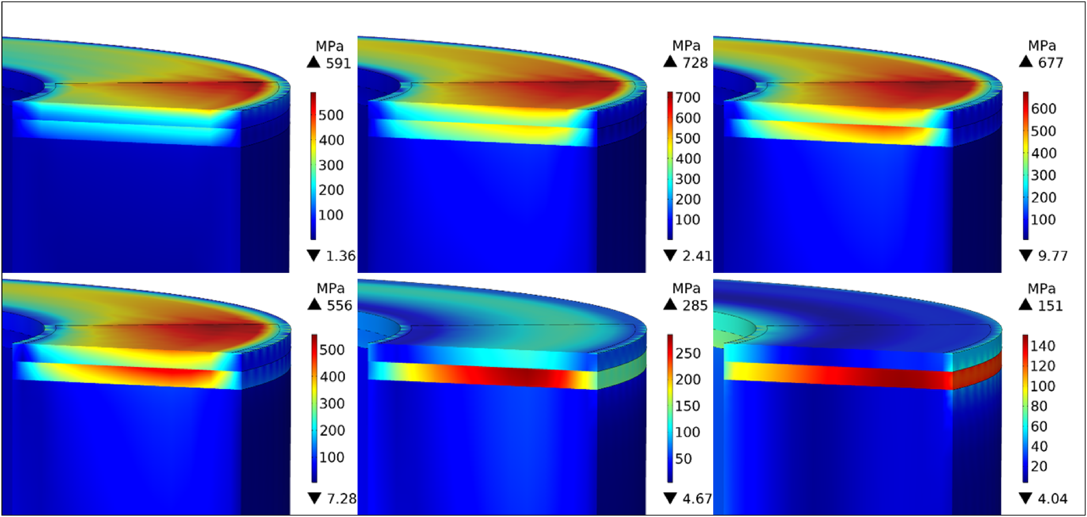
Cross-sectional zoomed-in coating displays of thermal stress contour maps for laser cladding (LC). Time instances are 0.1, 1 and 3 s of braking, from left to right sequentially (top row). Time instances are 5, 6 and 10 s of braking, from left to right sequentially (bottom row). Legend units: MPa.
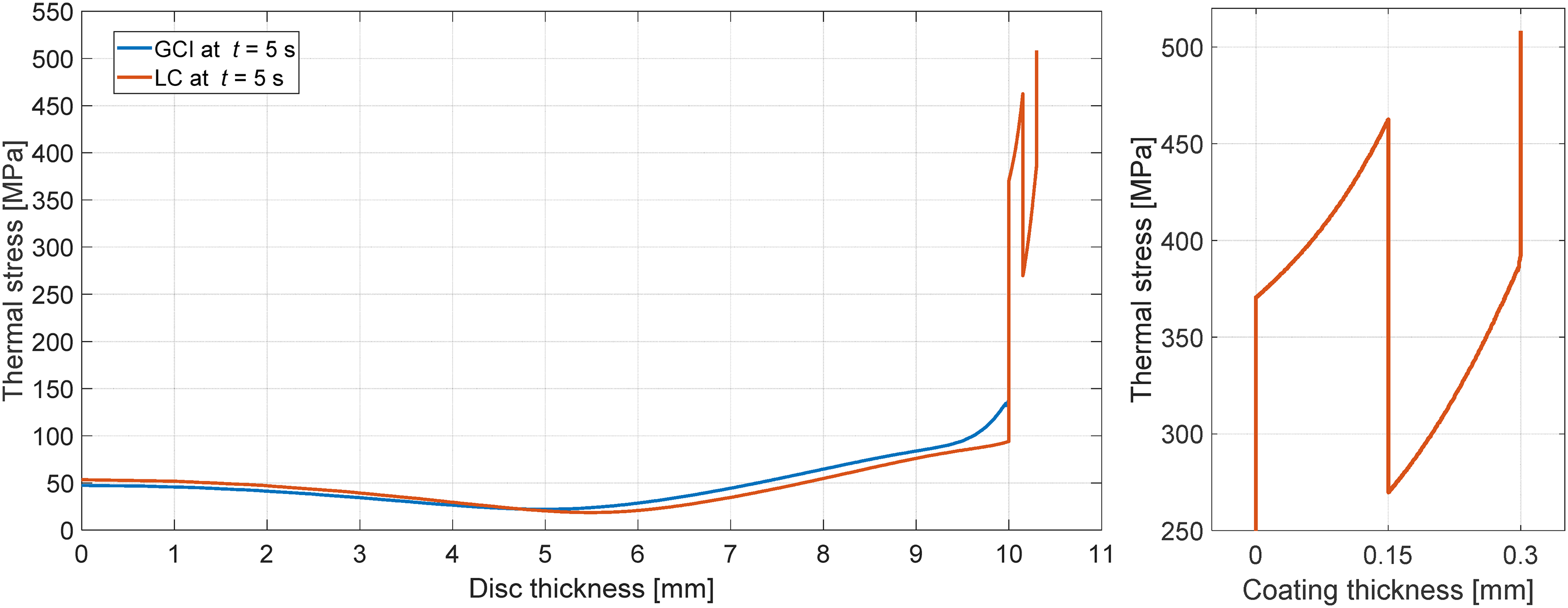
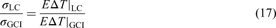
These final contour plots from Figure 8 show an evolution of interface stresses, which can be observed at interface regions with increase in time. The plot which represents a 5 s time instant, can be linked back to the plot displayed in Figure 7 for clarity. It is clear how at 6 s, when the brake pad has been released, surface stresses begin to decrease as the disc is undergoing cooling. Stresses are consequently stored in the interlayer where they require a longer period of time to dissipate. From the relationship below, it can be predicted that thermal stresses within the LC model will significantly surpass those of GCI:


Discussion
It is important to highlight that a braking power compensation was insured by adjusting the normal force applied to the LC rotor, in response to friction coefficient differences with GCI. This was in order to satisfy an equal rate of heat flux to both models, where differences were purely influenced by variations in heat partition coefficients. Therefore, a coherent comparison can be drawn from the obtained results of each model.
Regarding thermal performance, GCI does in fact seem to infiltrate more heat into the body of the disc as opposed to LC. It is also clear through the comparison that the coating creates an extremely localised temperature at the surface, observed by the steep gradient that peaks once the nickel-based alloy interlayer is reached.
Reasons for this high temperature peak at the LC surface relate back to the fact that the surface material, martensitic stainless steel has a lower thermal conductivity meaning it is less capable of diffusing heat across it, as well as the underlayer which introduces a visibly steep temperature gradient. This also demonstrates that the nickel-based alloy inter-layer performs as a thermal barrier resulting from its low conductivity and diffusivity. Therefore, as overall conduction is lower, LC stores more thermal energy at the upper surface where the pad–disc contact occurs. However, it is crucial to take into consideration that the coefficient of heat partition of the LC surface is
Now looking into thermal stress performance for LC, it is visible how significant peaks are developed at each interface layer of the laser cladded coating, whereas the remaining interior of the disc is not experiencing a significant stress magnitude. This compares very clearly to GCI that displays again a very gradual development of stresses reaching a maximum at the disc extremity. As has been expected consequently, boundaries of the laser cladded layers experience very high thermal stresses due to the fact that they act as constraints to each other, impeding their volumetric thermal expansion as their internal energy increases. Different rates of heat being received by different materials, each with different thermal expansion coefficients therefore introduces a very significant risk when it comes to the LC deposition. Due to its highest expansion coefficient value from the three materials and as the layer constrained by both its upper and lower interfaces, 5 the nickel-based alloy interlayer is therefore experiencing the highest level of thermal stresses. Therefore, the LC process must be done with extra care in the deposition procedure, in order to correctly align the thermal expansion magnitudes 5 to those which best satisfy the stress predictions at bonding regions.
In summary, the temperature field has demonstrated that LC is capable of generating much higher temperatures than GCI. Its higher friction coefficient introduces a stronger and more reliable braking performance and heat infiltration is minimised with respect to the range of overall generated temperatures. This combination of bonded materials brings about a different distribution of thermal energy as opposed to a conventional GCI disc model.
The stress field on the other hand has studied the constraint requirements that an LC model must be able to withstand for it to be successfully implemented. Hence, high developed stresses occur at the layer interfaces 15 which challenges the LC application process in optimising the metallurgical bonding and layer deposition. Accuracy techniques must be re-evaluated to determine a specific bonding tolerance that could be compared to modelled results.
An analysis of mechanical stresses must be conducted in order to determine load capabilities and the capacity of withstanding very high rotational shear stresses. Frictional forces which translate into rotational shear would, therefore, need to prove that the rotor compound is able to withstand the mechanical stresses associated with different stages of braking.
It is important to note that this project has analysed purely transient regimes, i.e. where inward and outward fluxes have been dominant in the studied time period. 16 The laser cladded performance should also be evaluated under steady-state scenarios such as in the case of a pin-on-disc tribometer where the input heat equals the output dissipation. 4 Time, gradient and steady-state level comparisons would offer another clear investigation into the reliability of the coating.
The research was also made to simulate an experimental performance made at room temperature, where the rotor was also set to perform at temperatures
Limitations of the study can be linked to a potential lack of surface topography detail. Therefore, as to what concerns surface texture, experimental iteration should be done to study the extent to which surface topography affects the tribological performance of braking. 17 If a significant influence is detected, such an effect would need to be implemented to improve the overall experimental validation of the model. Moreover, regarding parameters, a more accurate experiment would require evolving magnitudes of material data influenced by temperature changes. Thermal softening would provide the corresponding set of parameters for every temperature level such as a decrease in Young's modulus. As well as this, mean coefficient of friction values were used, inputted as constant parameters which were retrieved from experimental results.6,9 In a real case scenario, the friction coefficient evolves throughout a braking event in response to contact pressure variations and plateau dynamics. 9 Experimental recordings of friction coefficient values from pin-on-disc setups could be fed back into the simulation model even in the form of fluctuations for improvement. The FEA model would also benefit from more accurate and realistic convective heat transfer coefficient values. 18 Its validation would be optimised through a computational fluid dynamic study, by recreating the experimental setup. 16
Furthermore, it should be noted that for simplicity, heat flux distribution was assumed as being uniform. This limitation must be acknowledged given that non-uniformity due to transient regimes, constitute local hot spots in contact regions from focal heating.17,19 Considering plateaus to implement non-uniform contact pressures would provide a more realistic heat-flux distribution. 20 In addition, it must be said that maximum surface temperatures are also highly influenced by the heat partition coefficient which in reality, is not a static quantity. 20 It is dependent on temperature as well as contact pressure distribution, which evidently vary with time throughout a braking event. Given that dynamic modelling of the heat partition coefficient is particularly complicated, 21 simplicity was hence achieved using that proposed by Vernotte. 12 Hasselgruber, 22 Ginzburg, 23 and Charron 24 have also proposed different forms of determining heat partition coefficients which future simulations would benefit from.
Regarding the FEA model itself, there is no presence of the pad component. In consideration, its only influence is regarding the heat partition coefficient,
Therefore, the simulation model can be used for future optimisation and validation development, with the use of experimental data from LC rotors. By recreating the described scenario in a dynamometer test, full-scale experimental validation would be achieved.
Conclusions
Temperature and mechanical performance were investigated by the use of FEA modelling using COMSOL Multiphysics 5.6. A comparison was made between a laser cladded disc and a conventional homogeneous GCI disc. These models were primarily distinguished by the laser cladded model consisting of a material combination involving a nickel-based alloy interlayer and martensitic stainless steel overlayer surface. A highly simplified and computational cost-effective FEA model was delivered. The summarised conclusions were drawn as follows:
Meshing of the LC coating and GCI substrate is easily and effectively achieved, at reduced computationally cost, to validate interior temperature and thermal stress data of the FEA model, using the given mesh combination. The LC nickel-based alloy interlayer proves to act as a thermal obstructer to temperatures infiltrating the GCI substrate. Peak surface temperatures of LC attain 18% higher values as opposed to GCI, within the first second of braking. This peak temperature difference decreases over further braking time. The LC interlayer (Inconel 718) presents difficulty in effectively dissipating thermal stresses from its domain even after the brake pad is released from the disc. Peak thermal stresses of LC reach values which are 3.7 times those of GCI after 5 seconds of braking. For a 5 s braking event using an LC model, thermal stresses reach magnitudes superior to
Footnotes
Acknowledgements
The authors are grateful for the contributions provided by Fabrizio Girolimetti on simulation development.
Declaration of Conflicting Interests
The authors declared no potential conflicts of interest with respect to the research, authorship and/or publication of this article.
Funding
The authors received no financial support for the research, authorship and/or publication of this article.