
Abstract
Conventional conical hydrostatic bearings are compared with less conventional three-recess and four-recess designs for operation in hybrid hydrostatic/hydrodynamic mode. Design implications are discussed with reference to operation at either low or high speeds. Conical spindle bearings are chosen for this study because they offer a compact arrangement that allows both radial load support and axial load support. While there is wide availability of design data for separate thrust and cylindrical journal bearings, there are very little data for conical bearings. This paper reviews the design of conical bearings and extends from previous knowledge into hybrid performance at high speeds. It is shown that long narrow recesses provide larger radial load support compared to long wide recesses for higher speeds. Sample data are provided for design of single cone bearings and also for opposed cone bearings. The data provide for radial and axial loads applied in combination for a selection of cone angles. Data are also provided as a guide for flowrate in the concentric bearing state and for effects on temperature rise.
Introduction
Conical hydrostatic journal bearings can be employed for thrust bearings or for spindle bearings arrangements. Conical arrangements have advantages compared with separate journal and thrust bearings. Only two bearings are required for conical designs compared with two journal bearings and two thrust bearings for separate arrangements. This makes for economy of flow, economy of power and fewer parts. Furthermore, clearance is adjustable on assembly by adjustment of the axial location. However, accurate machining and accurate assembly of conical designs are required to ensure bearing alignment. The recesses for conical designs are relatively simple to manufacture by electro-discharge machining using a graphite carbon electrode suitably shaped that can be advanced axially into the bearing cones.
For brevity, the following research review is limited to publications on conical hydrostatic journal bearings, since there are hundreds of papers on other hydrostatic bearings.
Conical spindle bearings were applied by the author in 1967 for a precision grinding spindle used in an optical profile grinding machine.1,2 The spindle operated at 7000 r/min and was remarkable for its smooth running and precision grinding performance. Approximate load and flow equations for hydrostatic conical bearings were published by Stansfield in 1970. 3 Aston et al. computed load and flow using the lumped parameter technique.4,5 Ettles and Svoboda in 1975 investigated a double conical bearing for high speeds and commented on geometrical constraints limiting the cone angles that could be employed. 6 This unconventional design was basically a hydrodynamic conical bearing, although a degree of external pressurization was introduced to overcome insufficient radial load support. Rowe provided design procedures for hydrostatic conical bearings based on design maps derived for axial and radial loads applied in combination. 7 Sharma et al. provided results for capillary compensated conical hydrostatic bearings. 8 Rowe extended the design data in reference 7 using finite difference (FD) computer solutions for greater accuracy and range of application. Data and design procedures were made available for both hydrostatic and aerostatic conical bearings including complementary cone arrangements. 9 Zuo et al. published a new design of conical hydrostatic journal bearing where in-built restrictor lands introduce self-compensation. 10 It offers benefits of increased radial stiffness but introduces further complexity into the mechanical structure. Khakse et al. analysed non-recessed hydrostatic conical journals with hole entry, having either capillary or orifice restrictors. 11 The load performance was compared with and shown to be very similar to non-recessed slot entry cylindrical plain bearings as described in Rowe. 9 The unified design approach used for definition of the speed domain in Rowe 7 was confirmed by Bassani and Piccigallo in 1992, and gave comparable results for hybrid cylindrical plain bearings. 12
The design data for the conical hydrostatic bearings up to this point ignore hydrodynamic lift at high speeds. In practice, load support can be greatly increased as shown for cylindrical journals by taking advantage of hydrodynamic forces.9–12 The extra lift provides additional safeguard for radial overload and offers an increased range of application. This study advances previous work by exploring combined hydrostatic and hydrodynamic load support at high speeds, employing either four recesses or three recesses to maximize plain bearing land area where it is most useful. It is shown that long and narrow or thin-recess bearings offer excellent hybrid load performance compared with wide-recess bearings and also offer strong scavenging flow to offset hot spot generation. Optimization procedures allow hybrid loads to be maximized and make it possible to critically assess safe operating regions.
Bearing arrangements
Bearing configurations are compared in Figure 1(a) and (b). The conventional conical hydrostatic bearing with four wide recesses is shown in Figure 1(a). The proposed bearing with three narrow recesses is shown in Figure 1(b). Both types of bearing carry applied loads by means of an external pump and a constant supply pressure (a) A conventional four-recess conical hydrostatic bearing with wide recesses.
9
(b) A three-recess conical hydrostatic bearing with long thin recesses.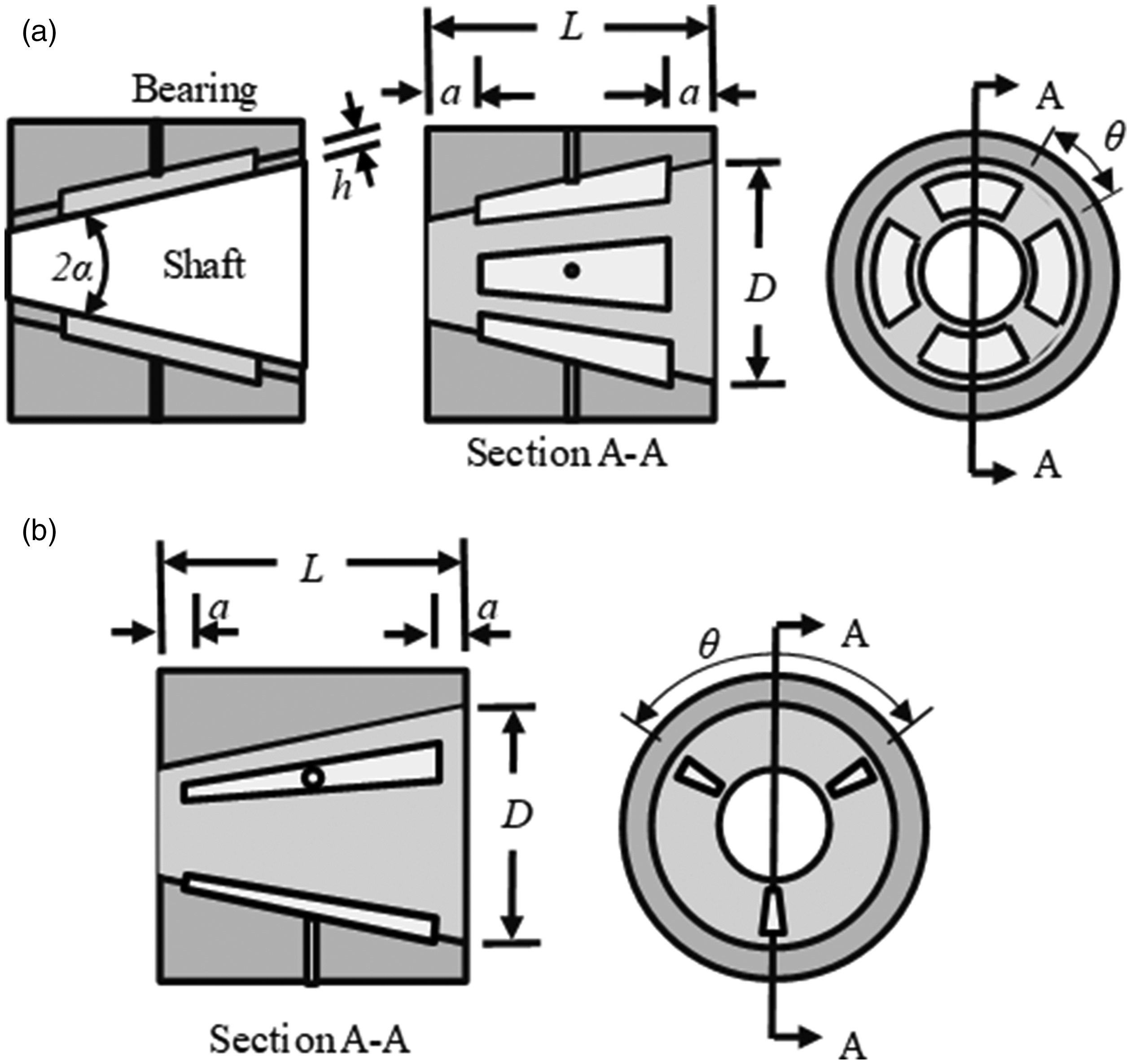
The design and operation of basic cylindrical hydrostatic bearings are well understood, and Rowe 9 provides detailed information on many aspects. The purpose of this paper is to establish basic principles and data for conical hybrid journal bearings operating at low to high speeds. It is also shown that a 4-recess bearing designed with long thin recesses offers hybrid performance almost as good as the 3-recess bearing with long thin recesses. Both designs offer much better load support than a conventional wide recess bearing.
The long thin recesses shown in Figure 1(b) lead to wide inter-recess lands. The wide inter-recess lands allow substantial hydrodynamic pressures to be generated. Another advantage is that the long thin recesses allow cooling flow to be distributed along the length of the bearing.
Possible configurations for opposed pad complementary-cone arrangements are illustrated in Figure 2. The two conical bearings at each end of the spindle should be well separated as shown rather than closely spaced. Close spacing is not recommended as explained more fully by Rowe.
9
Wide spacing allows either central application of radial loads or, as more usual, overhung application of radial loads. The advantage of a widely spaced arrangement is that a slight tilt allows the total radial load supported to be almost doubled. With closely spaced bearings, a slight tilt greatly reduces minimum film thickness. Initial alignment during manufacture is also simplified with widely spaced arrangements.
Alternative arrangements for overhung loads. (a) Best for zero-speed radial load capacity and (b) best for high-speed radial load capacity.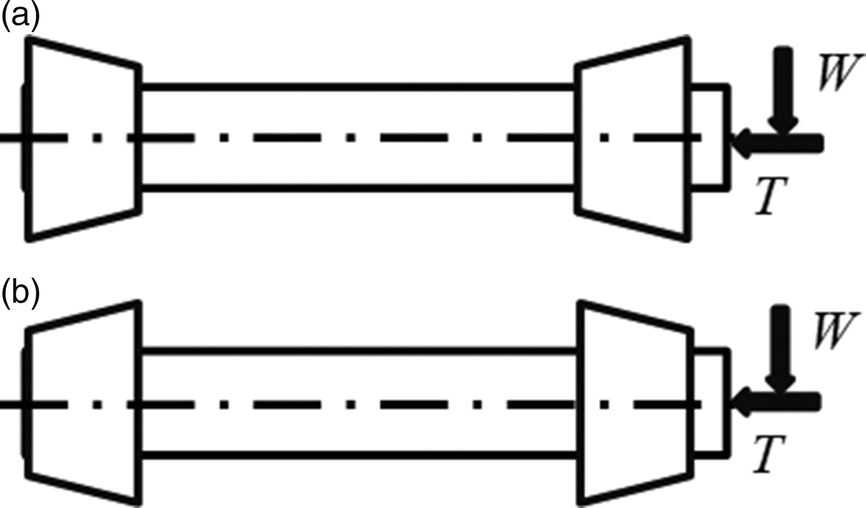
Data are given below for a single cone while progressing development of suitable parameters for hybrid operation. Subsequent data are given for opposed pad bearings. Data are given for the maximum radial load that can be supported on one bearing, while the maximum thrust load is for the opposed pair acting together. The designer must first specify the maximum radial and thrust reaction loads and then evaluate the radial reaction forces on each bearing. Specified radial and thrust loads must not be exceeded. Exceeding the specified thrust load reduces the radial load that can be supported and also reduces the minimum film thickness.
If axial thrust loads applied to the journal are very small in comparison with radial loads, a small cone angle is best. However, if applied thrust loads are large, it may be necessary to design for a larger cone angle. Data are provided for four cone angles covering a suitable range. It is considered that a semi-cone angle of 15° is large enough to satisfy most situations.
This paper documents the development of suitable hybrid conical bearings. It also provides computed data for supported loads. Four-recess bearings are compared with three-recess bearings for hybrid performance over a range of zero, moderate and high speeds.
Theoretical analysis
Finite difference solution of the pressure field
The basic equations for hydrostatic lubrication are well known and established. For this paper, it is therefore only necessary to give a brief description of the basic theory and computational stages involved. A form of the Reynolds equation for steady loading of the fluid bearing film allowing for varying diameter and speed along the length is
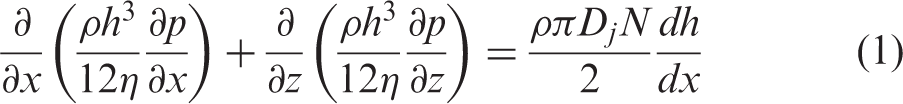
In parallel with solution of the bearing film pressures, it is necessary to solve the recess pressures. A finite difference (FD) technique was employed to solve the Reynolds equation, first solving the concentric film pressures using the concentric recess pressures as the internal boundary condition. Typically, a 150 × 40 FD grid was employed, denominating position nodes i = 1 to n g = 150 around the circumference and j = 1 to m = 40 along the length.
The FD equation employed for solution of the bearing film pressures has the form
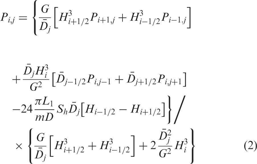
At high speeds and radial eccentricity ratios, hydrodynamic bearings cavitate. This is the situation where bearing pressures in the diverging film region initially become negative and then with further eccentricity the negative fluid film stresses collapse back to zero as the fluid film ruptures. This situation is accommodated in the computation using the usual approximation where negative pressures are set to zero.
After successive iterations of the pressure field, convergence is achieved. From the derived pressures, it is possible to sum the bearing flows through the whole bearing and also through each restrictor and recess.
The recess inlet pressures depend both on the resistance characteristics of the flow restrictors and the bearing film flow resistances from each recess. The subject of flow restrictors is fully described in Chapter 5 of Rowe.
9
For the purpose of solving the conical bearing, the subject can be understood as follows. The flow out from each recess must equal the flow in through the appropriate restrictor. The flow from the rth recess may be calculated by summing the individual dimensionless flows
Flow summation performed for the concentric shaft yields a value

The capillary factor
Flow summation from the rth recess performed for the eccentric shaft yields a value
During the iteration process, new values of recess pressure can therefore be derived with some manipulation by substituting the FD expression for

Successive iterations of film pressures and recess pressures leads to a stable convergence of the pressure, load and flow parameters until sufficient accuracy is achieved. Better than 0.1% is usually considered satisfactory. Following convergence of the pressure field, bearing flows and reaction forces are summed in the usual way.
Axial displacement ratio and radial eccentricity ratio
Radial eccentricity ratio is
When axial and radial loads are employed together, it is advisable to base design values conservatively, particularly for the cone having reduced film thickness. Axial displacement ratio of 0.2 for a complementary cone arrangement gives film thickness values of
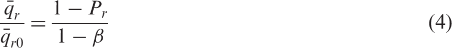
Concentric pressure ratio
Restrictors for hydrostatic bearings are generally designed so that concentric pressure ratio
Large variations from
Power ratio and speed parameter
It is not always realized that power ratio is a great simplification in bearing design allowing selection of suitable combinations of design variables such as speed, viscosity, clearance and landwidth ratio. It was shown by Opitz that the minimum power when varying viscosity for a particular speed is obtained when the power ratio
Power ratio K is closely related to the widely employed speed parameter
Running at speeds within the optimum range for hydrostatic operation yields increased bearing load support as seen in the results that follow. However, deliberately designing the bearing geometry for increased hydrodynamic load support and at the same time further increasing the power ratio reduces hydrostatic load support but increases total load support. Increasing the power ratio from
For a particular bearing geometry and concentric pressure ratio, an expression for concentric speed parameter can be determined from the parameter definitions given
9

Equation (7) is a convenient form for calculating required numerical values for
Adiabatic temperature rise
At zero speed, the adiabatic temperature rise of a liquid bearing lubricant can be found by assuming pressure energy is all converted into heat. The temperature rise depends on the supply pressure

Temperature rises with time if the heated lubricant is allowed to re-enter the bearing. Temperature rise with time can be prevented by cooling the lubricant in a cooler. Temperature rise can also be reduced if the liquid is cooled after passing through the restrictors and before passing through the bearing.
At speed, the heat energy is increased by frictional heating as the liquid passes through the bearing. The total temperature rise including the effect of supply pressure and frictional heating for a single pass through the bearing can be estimated very conveniently based on the power ratio K

For a typical zero speed bearing employing light oil as a lubricant, the maximum temperature rise of the oil passing through the bearing is
Flowrate
Concentric flow can be calculated based on a one-dimensional (1D) solution
3
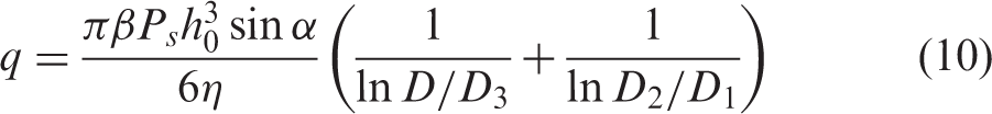
A 1D flow solution gives a reasonable estimate for circumferentially wide recesses and large
1D concentric flow solutions using equation (10) are the same for three- or four-recess bearings.
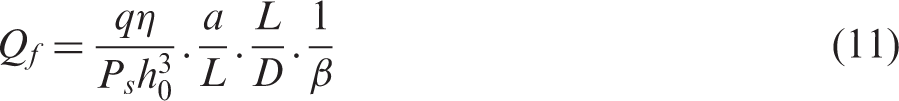
The flow through each restrictor is given by
Results
Hydrostatic performance at zero speed
Figure 3 shows pressure contours for a conventional conical hydrostatic bearing having four large recesses running at zero speed, where L/D = 1.0 semi-cone angle is Pressures: 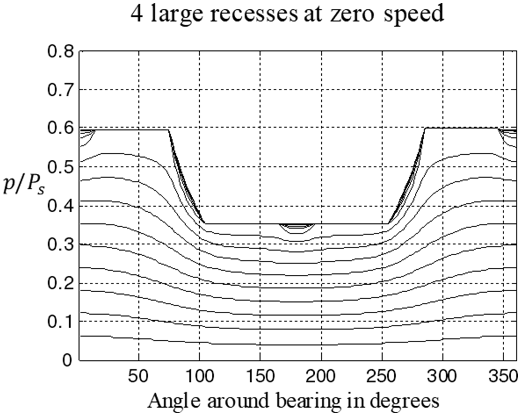
Figure 4 shows the load support at zero speed for the same large recess bearing. Zero speed corresponds to a power ratio Load support: 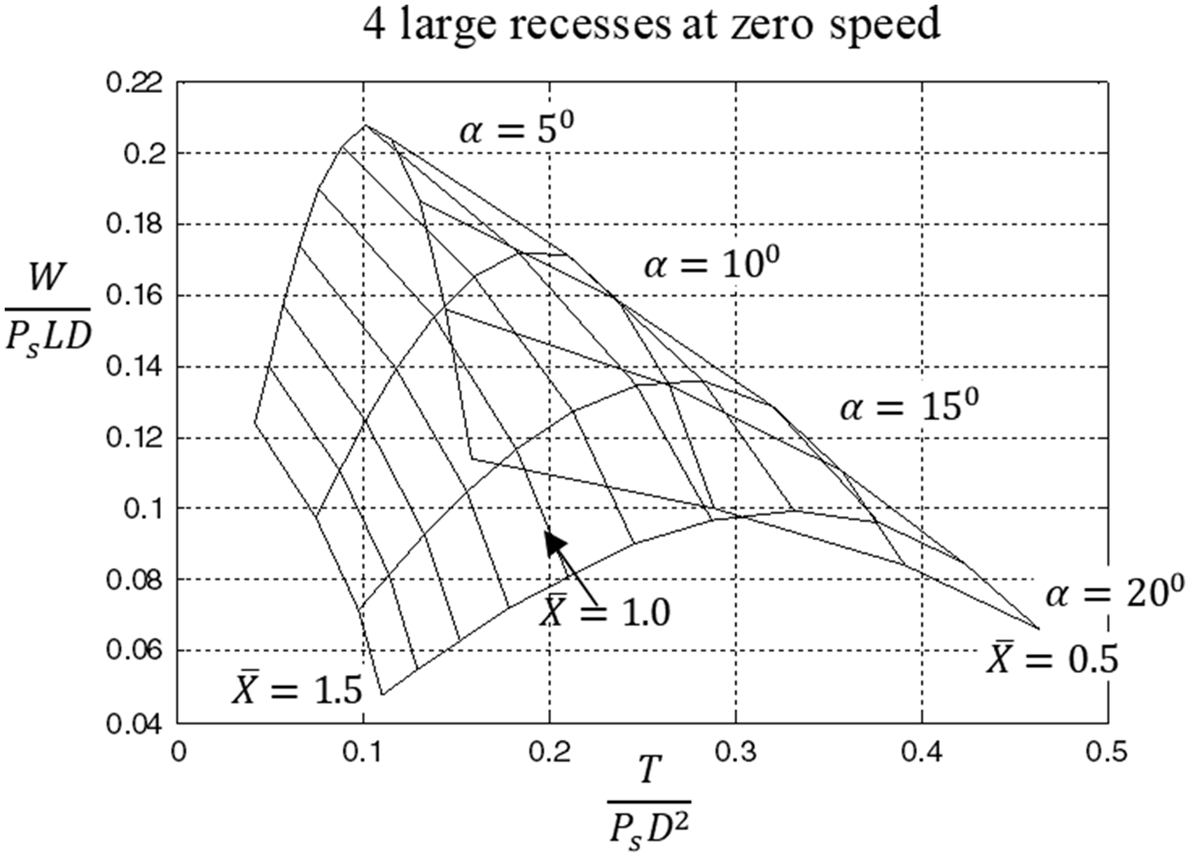
Figure 5 demonstrates that these changes provide adequate load support even at zero speed. Figure 5 is for the developed geometry with three thin recesses. Combining reduced axial land width Load support. 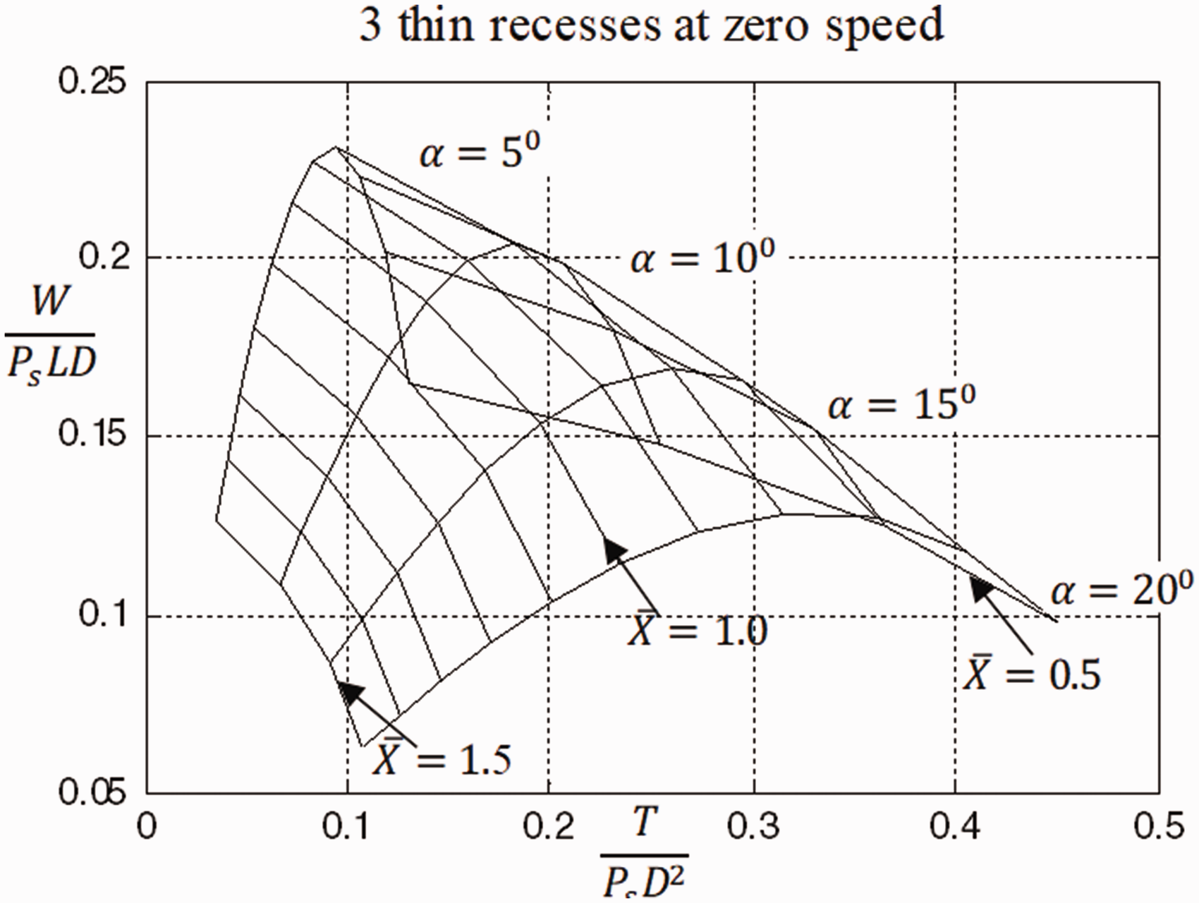
Since long thin recesses were so successful for the three-recess bearing, a similar change was tried for a four-recess bearing where the recess angle was reduced to Load support. 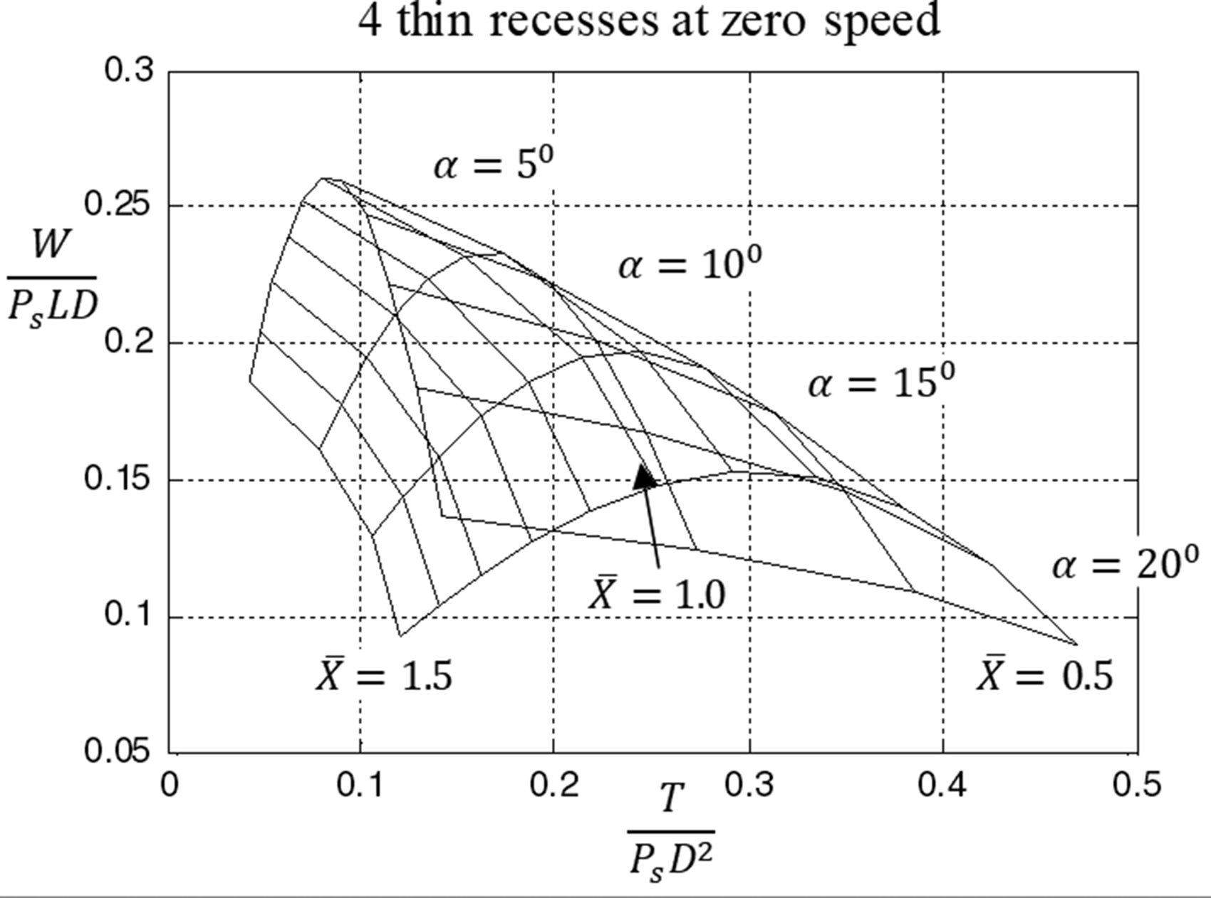
Hybrid performance at low to moderate speeds
The optimum power ratio K for purely hydrostatic load support lies in the range 1 to 3. The higher power ratio represents a speed nine times higher than the lower value. The value Pressures: 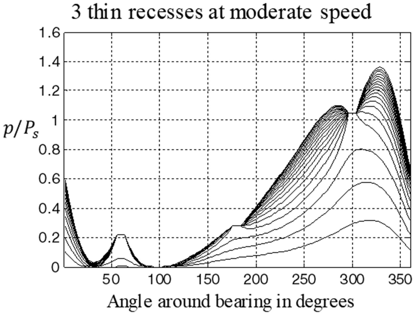
Although pressures are not shown for the four-recess bearing for the moderate speed condition, the maximum pressure supporting the load was found to be nearly 10% higher for the three-recess bearing than for the four-recess bearing.
Figures 8 and 9 show bearing support loads for the two hybrid bearings for Loads and ɛ: Loads and ɛ: 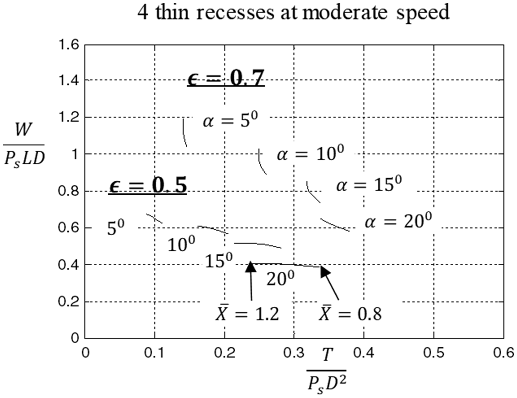
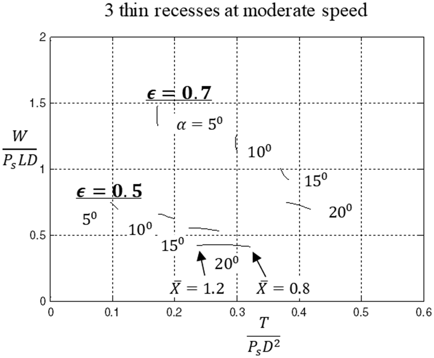
Figure 10 compares the effect of directing the radial eccentricity towards the middle of the inter-recess land Effect of φ: 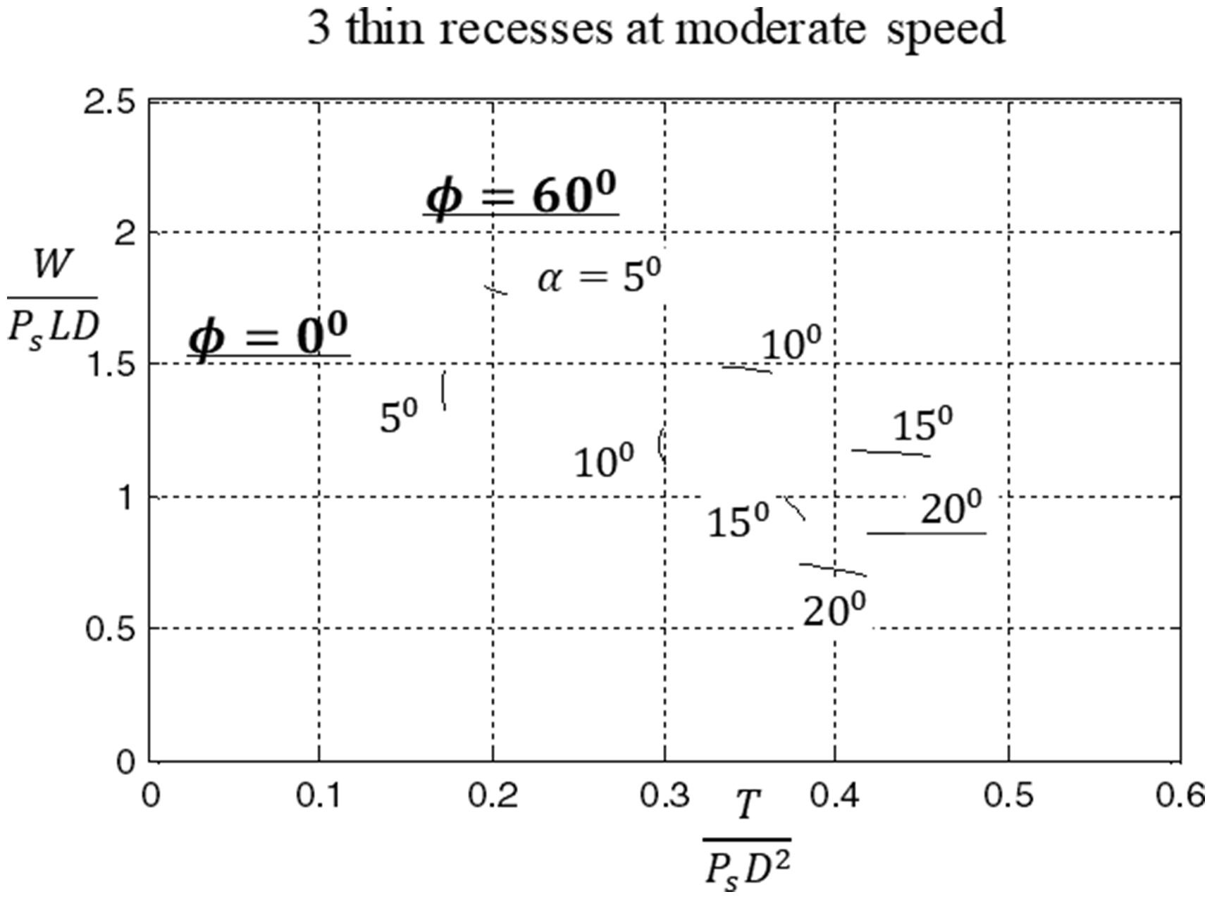
In practice, the direction of the line of eccentricity is usually unknown at the design stage. The attitude angle ψ between the direction of the applied load and the line of eccentricity varies both with eccentricity ratio and with power ratio as shown in Figure 11. For a large inter-recess land, Attitude angle ψ & ɛ 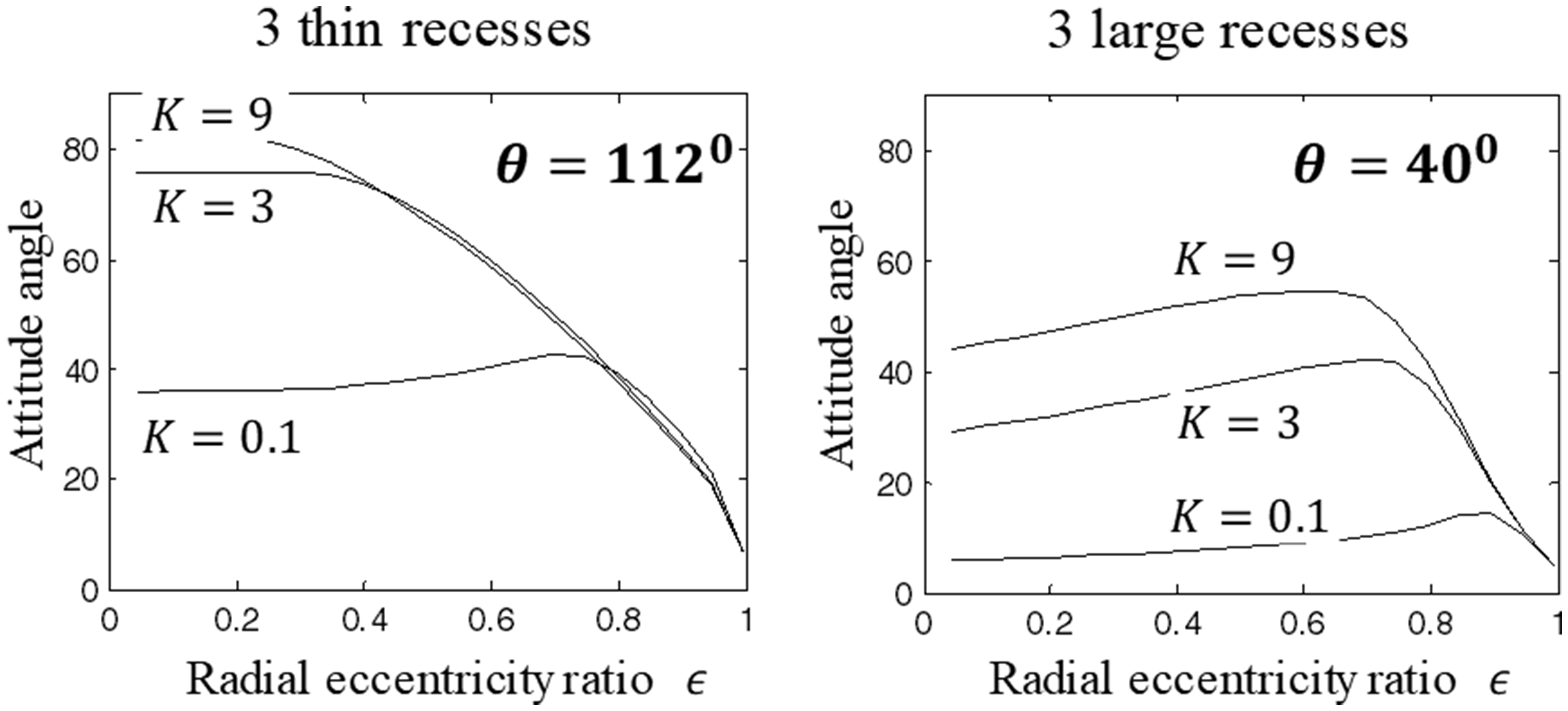
Figure 11 also shows a more conventional hydrostatic bearing with three large recesses where the inter-recess land
Hybrid performance at high speed
Previous experimental and theoretical research on conventional recessed hydrostatic journal bearings showed that hybrid bearings could operate at much higher values of power ratio than
At high speed, Pressures: 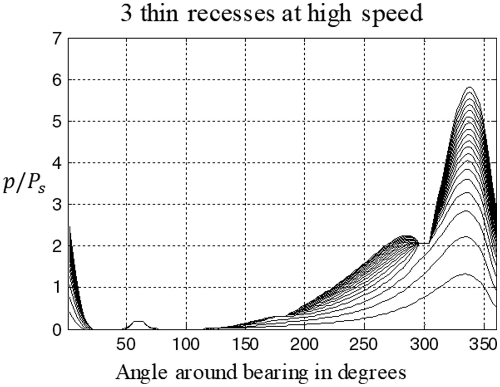
Figure 13 for the three-recess bearing at high speed compared with Figure 6 for the conventional zero-speed four-recess bearing shows that radial load support is almost quadrupled at Loads: Loads: 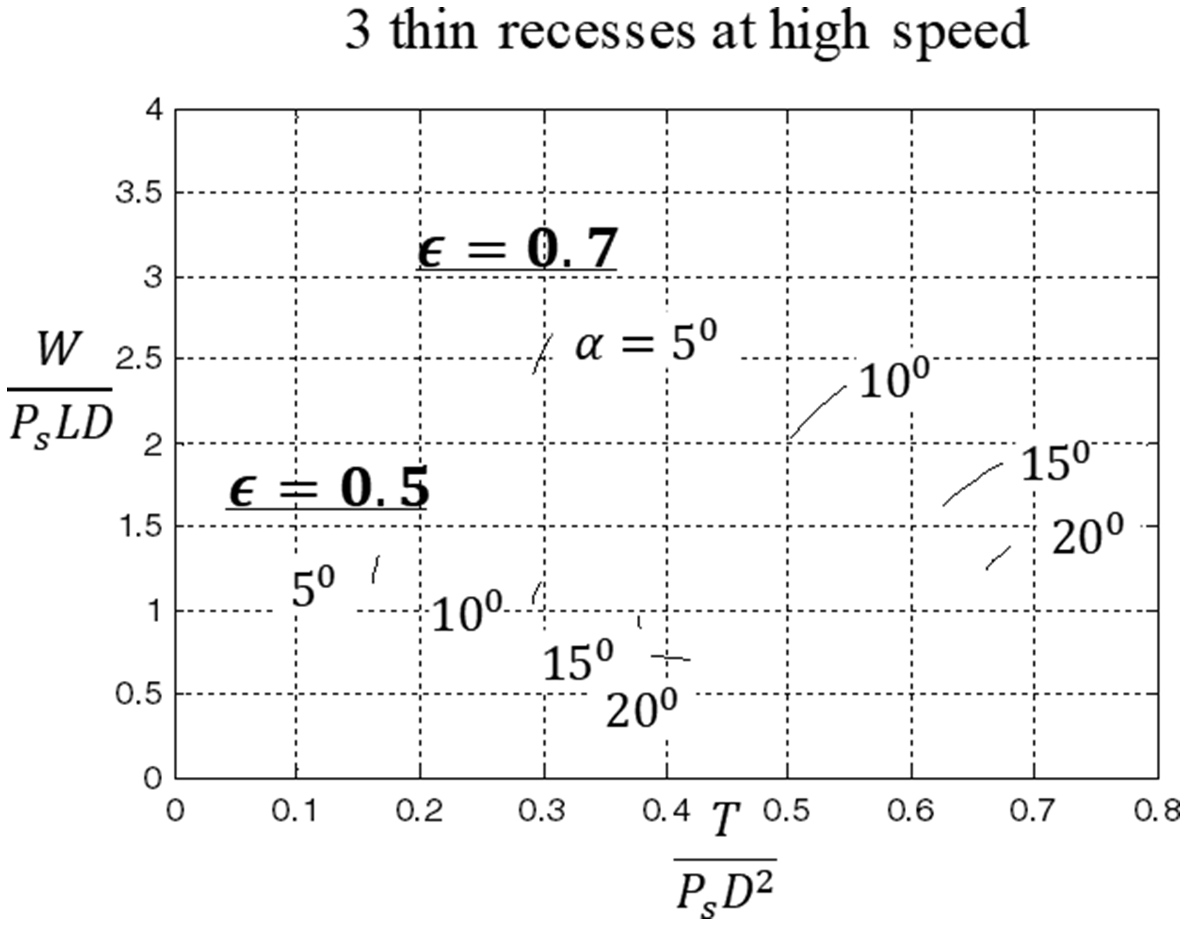
For even higher values of power ratio, where
Load support varies significantly depending on the eccentricity ratio, and also on the position of the recesses relative to the direction of the applied loads, as seen in Figures 9 and 10. Figure 15 shows that the difference between the minimum radial load support and the maximum radial load support is almost 80% at an eccentricity ratio Load support with 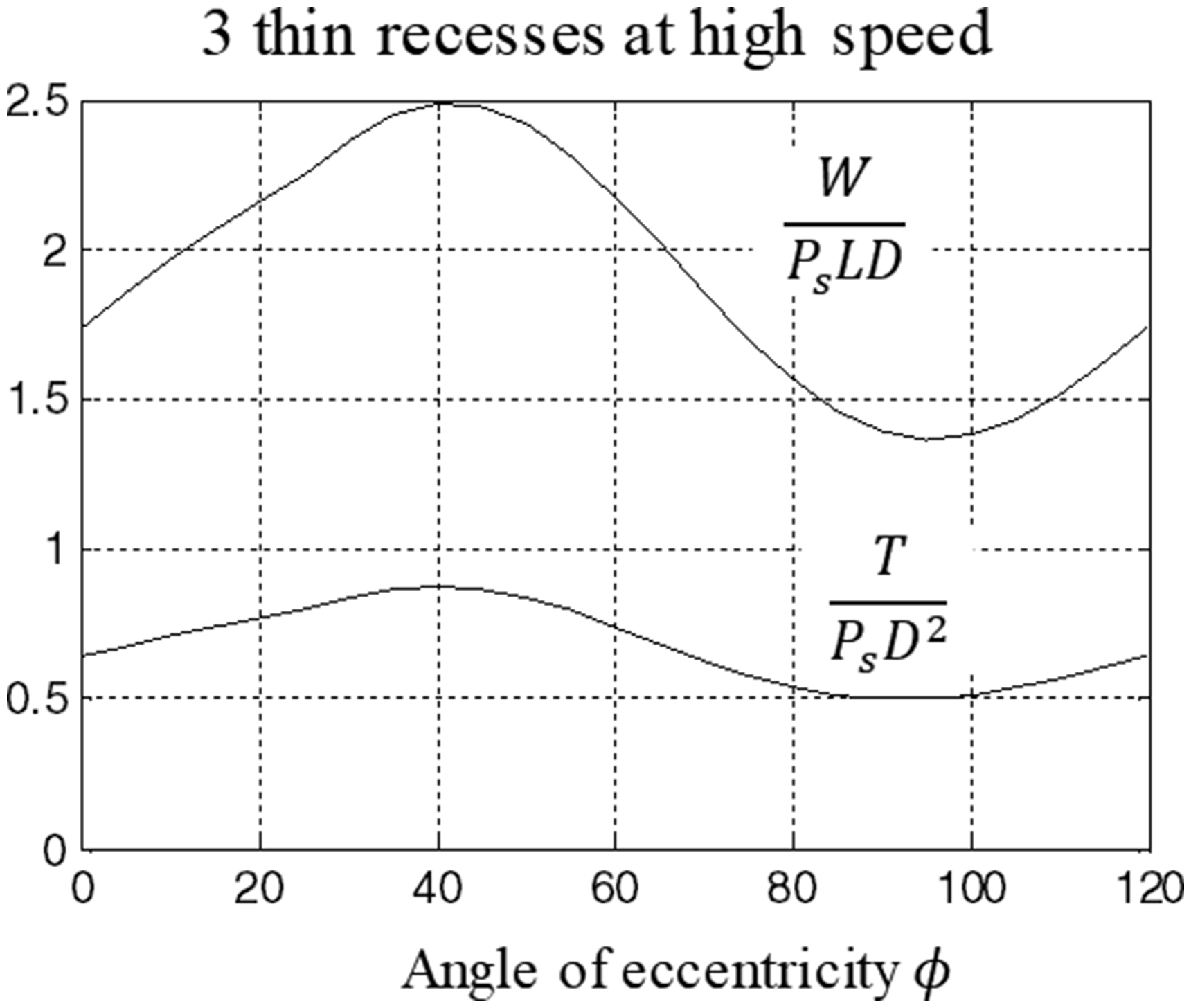
Load support for complementary-cone arrangements
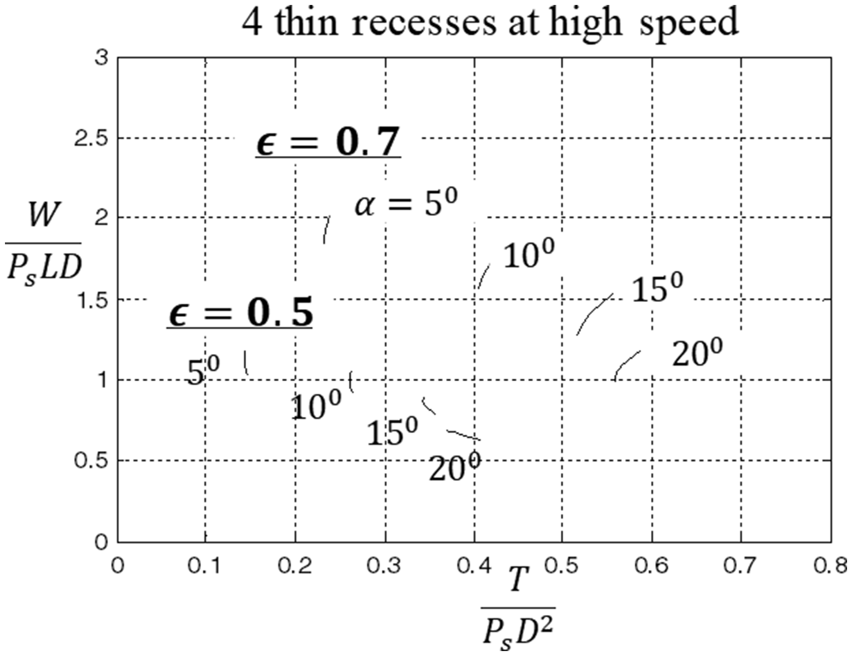
Two complementary-cone arrangements are shown schematically in Figure 2, where two conical bearings provide axial thrust loads acting in opposition. Complementary cone arrangements are convenient for spindles that have to support overhung loads as shown. The more centrally located bearing nearest the overhung load experiences the maximum radial load. The two conical bearings must be well separated so as to avoid excessive misalignment of the journal and bearings under the action of radial loads. Maximum radial load on the front bearing has to be supported based on the data provided in the above figures for a single cone bearing. However, the maximum axial load depends on the resultant axial support load for the two bearings acting in combination. With zero externally applied load, the resultant axial thrust due to the two bearings is therefore zero, and the resultant axial thrust loads are much reduced compared to the thrust loads for a single pad in the range Thin recess complementary cones: Thin recess complementary cones: 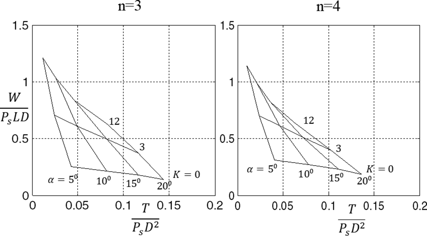
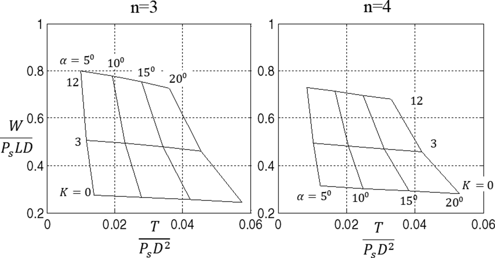
It can be seen that radial loads increase at the higher speeds corresponding to
While three-recess arrangements give slightly more load support than four-recess arrangements the difference is modest. Reducing the L/D ratio from 1 to 0.5 has the effect of reducing radial and axial loads.
Flowrate and flow factors
The main variables for the flow factor are the Concentric flow from 1D wide recess solution compared with accurate 2D thin recess solution: 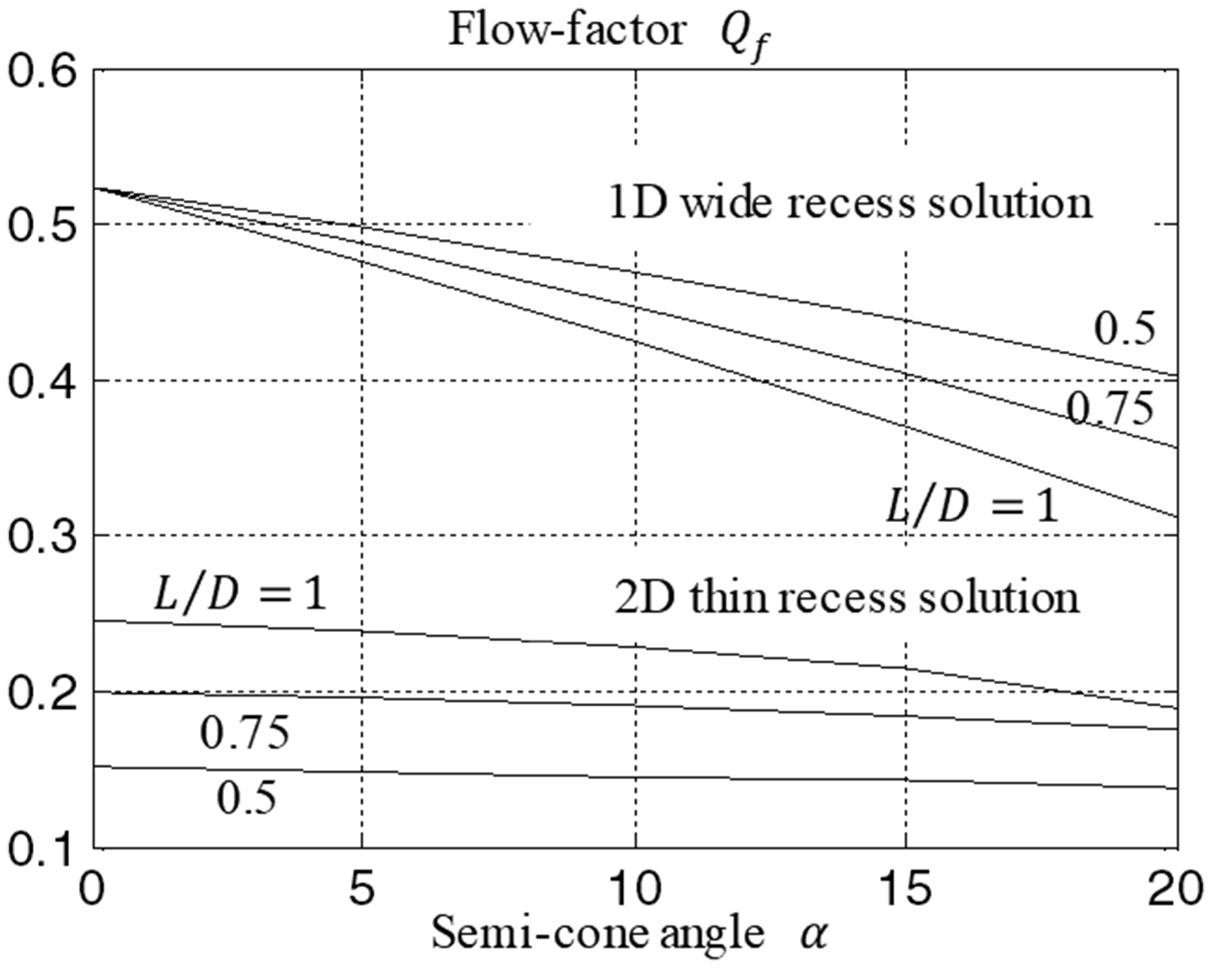
Flow factors are reduced in the 2D results due to pressure drop between the recesses and also to some extent due to eccentricity ratio. Figure 18 also gives concentric flow factors based on the accurate 2D solution for three thin recesses with
The flow factors for three and four recess bearings are increased as axial land width is increased, whereas actual values of flowrate q are reduced. This difference is a consequence of the definition of flow factor Concentric flow from 1D solution compared with accurate 2D thin recess solution: 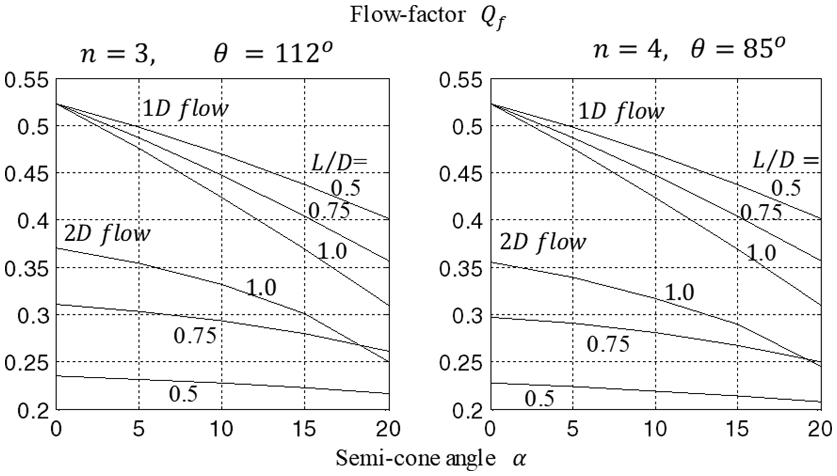
Conclusions
For high speeds, recessed conical hydrostatic bearings benefit from long and thin recesses as opposed to low speed bearings where wide recesses are usually employed. Three and four recess bearings employing long and thin recesses perform well throughout the speed range from zero speed to high speed.
Speed ranges can be conveniently defined by employing power ratio in the design process. Bearings operating in the range
Data provided reveal the benefits for radial load support from operating at high speeds.
Footnotes
Declaration of Conflicting Interests
The author(s) declared no potential conflicts of interest with respect to the research, authorship, and/or publication of this article.
Funding
The author(s) received no financial support for the research, authorship, and/or publication of this article.