
Abstract
In order to accurately predict the lubricant film thickness and generated friction in any tribological contact, it is important to determine appropriate boundary conditions, taking into account the oil availability and extent of starvation. This paper presents a two-dimensional hydrodynamic model of a piston ring pack for prediction of lubricant film thickness, friction and total power loss. The model takes into account starvation caused by reverse flow at the conjunctional inlet wedge, and applied to a ring pack, comprising a compression and scraper ring. Inlet boundaries are calculated for an engine cycle of a four-cylinder, four-stroke gasoline engine operating at 1500 r/min with conditions pertaining to the New European Drive Cycle. The analysis shows the two main sources of starvation: first, due to a physical lack of inlet meniscus and second, due to reverse flow at the inlet wedge significantly affecting the prevailing conditions from the generally assumed idealised boundary conditions. Such an approach has not hitherto been reported in literature.
Introduction
Concern for pollution levels and greenhouse gas emissions has resulted in increasingly stringent directives and legislation affecting the automotive sector. Therefore, power train efficiency is now the key objective to alleviate these concerns. 1 Frictional power losses account for nearly 20% of all the losses in passenger vehicle internal combustion engines, with the piston–cylinder system share of these being 40–45%.2–4 To be able to mitigate these losses, it is essential to have detailed predictive methods. With engine downsizing a greater emphasis is put upon increased power-to-weight ratio in order to maintain or improve upon engine performance. With increased in-cylinder pressures, particularly during the power stroke, the conjunctional gaps between the piston ring pack and cylinder liner diminish. This can result in higher instances of direct interaction of contacting surfaces, thus increased friction and wear.5,6 It is therefore essential to be able to predict the lubricant film thickness for any given set of design and operational parameters.
There have been many contributions in the study of piston rings-to-cylinder liner contacts, featuring the effects of conjunctional geometry, surface topography, lubricant rheology, operating conditions (gas pressure, load, speed and temperature) and even surface materials, coatings and any surface modification.7–22 The ultimate aim is to reduce friction and wear.
In most applications, the piston ring pack comprises two compression rings, an oil control ring and a scraper ring. A model is required to determine the oil transport between these rings, in particular the quantity of oil left on the liner surface in the wake of a leading ring. This constitutes the inlet meniscus for a trailing ring which crucially affects its prevailing regime of lubrication. This issue is particularly important during the power stroke, where there is reduced lubricant availability at the top ring, with its inlet boundary starved of lubricant at high in-cylinder pressures. One of the most widely used oil transport models is that of Tian et al. 14 It makes use of the average flow model of Patir and Cheng.23,24 A one-dimensional model was developed to predict the lubricant film thickness and generated friction. The model was then extended to the case of three rings, assuming that in the downstroke sense of the piston there would always be a sufficient volume of lubricant available for the oil control ring conjunction. The boundary conditions imposed for the inlet considered a wetting location at the leading edge of the ring. The usual Reynolds exit boundary condition was replaced by a non-separation film condition, where the squeeze film lubrication may be considered to be dominant. It was shown that the top compression ring is able to carry a quantity of lubricant to the region above the top dead centre (TDC) of the oil control ring during the compression stroke. This is due to raised pressure in the region below the top ring. Surface roughness was also found to contribute significantly to the mechanism of oil transport.
Using floating liners to directly measure frictional characteristics of piston–cylinder system, it was found that boundary and mixed regimes of lubrication are prevalent at TDC reversals.25–27 The same experimental results indicated that at the inlet there would be an insufficient supply of lubricant for the compression ring during the upstroke motion of the piston. Therefore, inlet starvation should be taken into account when predicting the frictional losses. There are two main sources of starvation. One is due to a physical lack of lubricant which requires modelling of oil transport, comprising the inclusion of the entire ring pack to estimate the quantity of available lubricant for any trailing ring. The other is starvation due to reverse (counter) flow at the inlet boundary.28,29 This requires a numerical or an analytical flow analysis to predict the inlet stagnation boundary, beyond which no reverse flow occurs and the build-up of contact pressure commences. Post stagnation point, it can be assumed that the remaining volume of lubricant contributes to the oil flow into the conjunction proper. Tipei30,31 provided an analytical method for this purpose, predicting the location of the inlet stagnation boundary. Using this approach, it is possible to determine where an inlet boundary condition should be placed in a numerical model, as opposed to assuming an idealised fully flooded inlet at the edge of the ring, which is often assumed. This assumption can lead to over-optimistic predictions of lubricant film thickness. The results with realistic boundary conditions would be closer in conformance with the experimental measurements. 32
This paper presents a method for predicting inlet lubricant availability for piston ring pack, including the effect of starvation. The model comprises the leading and trailing compression rings’ conjunctions, as well as the oil transport between them. Tipei’s potential flow model approach is used in order to predict the zero reverse inlet boundary and estimate the extent of starvation. This approach has not hitherto been reported in literature.
Numerical method
Reynolds equation in its two-dimensional form for a compressible piezo-viscous lubricant can be expressed as
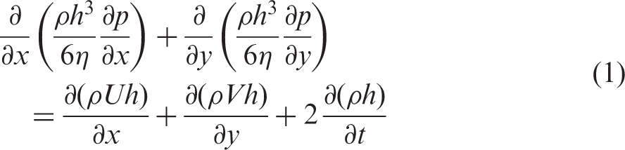
The above form of the equation includes flow in the direction of entraining motion, x, as well as side leakage, y. In the current analysis the side-leakage Couette flow is neglected as V = 0.
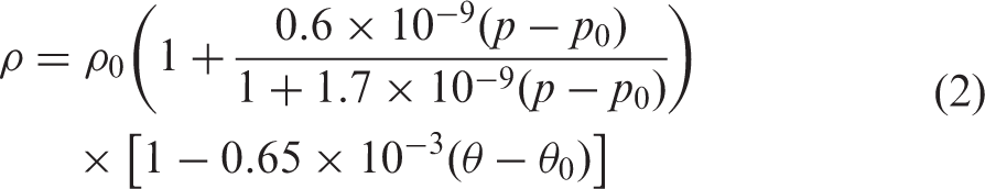
It is important to take into account the effect of pressure on the density of lubricant, especially in assemblies such as the piston ring pack. The Dowson and Higginson density model
33
is used

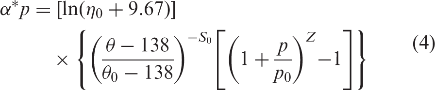
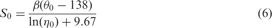
The constants Z and S0 are independent of both pressure and temperature

The minimum lubricant film thickness hm is obtained as
34

This equation does not take into account any localised deflection of the contiguous bodies in contact or their thermoelastic deformation. Bolander et al. 38 and Mishra et al. 39 show that the generated contact pressures in ring–liner conjunction are insufficient to cause any localised contact deflection. In practice, the rings can undergo modal behaviour as shown by Baker et al. 40 Since this analysis is based on a passenger vehicle, the effects of elastic deformation are not taken into account in the current analysis. 41
The ring profile is assumed to be parabolic
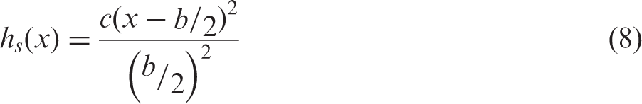
This approach can be adopted and any profile for either the top compression or scraper ring can be incorporated in the model. Extra rings such as the oil control ring can also be added. Since this study focuses on tackling the numerical solution for starvation and reverse flow, for proof of concept it is more suitable to use two identical rings.
The radial outward forces acting on the top compression ring, pressing it into the cylinder liner are

The gas force, Fg, acts behind the inner rim of the ring, where the combustion pressure, pg, is obtained from the combustion pressure curve in Figure 4

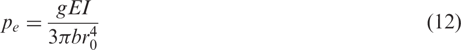
Assuming the ring has a rectangular cross section, the elastic ring tension force, Fe, is found as a function of the elastic pressure, pe as


In the current analysis, as in the majority of the reported studies, an ideal right circular cylindrical liner is assumed, thus the compression and scraper rings conform to the bore. In practice, the cylinder is out of round as described by Ma et al. 19 and Rahmani et al. 16
It is assumed that the hydrodynamic reaction and asperity contact forces act on the ring running face and equilibrate the applied ring tension and gas forces. The hydrodynamic reaction is obtained as
The Greenwood and Tripp42,43 method is used to calculate the asperity contact load within the conjunction
The roughness parameter (
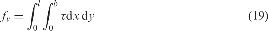
The total generated friction is

The boundary friction due to interaction of asperities is calculated as


The viscous friction is obtained as
Boundary conditions, starvation due to the reverse flow
Fully flooded condition is assumed in the majority of reported hydrodynamic analyses and has been used in the case of piston ring–cylinder liner conjunction.15,16,20,44 This assumes that a sufficient volume of lubricant would be available at the inlet of each ring in the ring pack. Hence, the edge of the ring is taken as the position of the inlet meniscus. Thus

Tipei 30 found that although the two-dimensional solution of Reynolds equation is applicable for practical problems, the justification of two-dimensional flow continuity condition is only valid for special cases. It was shown that only a fraction of the inlet-bound flow is actually drawn into the contact of the contiguous surfaces for any given geometry, load and speed, whilst forming swirl flows upstream of a stagnation point. The excess flow undergoes side leakage from the contact. 31
Reverse flow at the inlet and consequent starvation
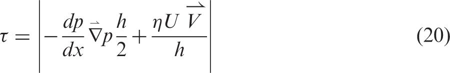
Figure 2 shows the total flow into the inlet wedge. Only a portion of this flow is entrained into the contact (Q2), whilst some of the flow reverses outwards (i.e. reverse flow, Definition of variables. Velocity and rates of flow distribution with counter flow.
30
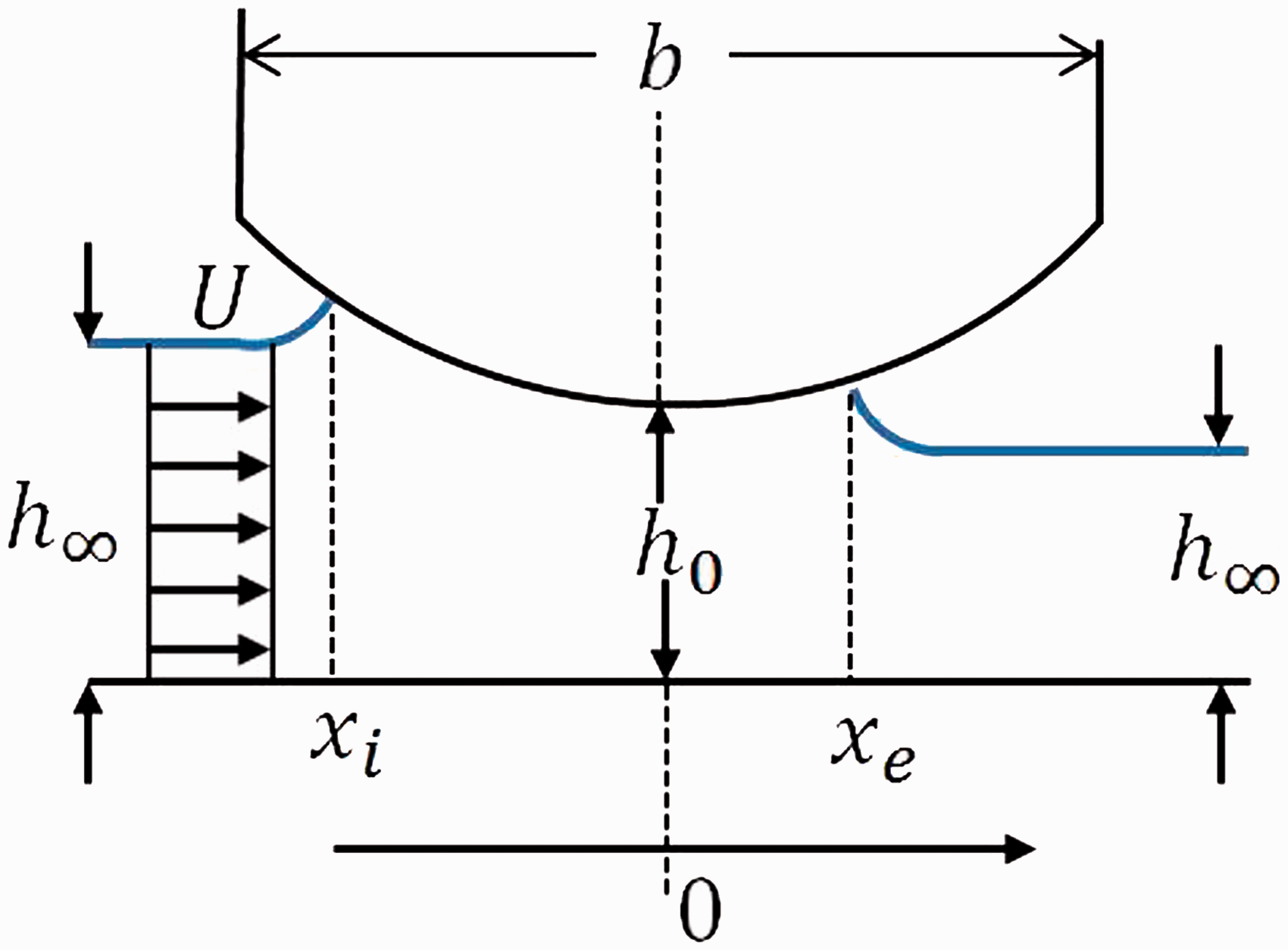
Figure 3 represents the inward flow motion, assuming upstream lubricant wetting of both the contacting surfaces. It can be seen that the flow field contains two inward bound vortices, generating a close streamline.
Flow in the inlet region.
30
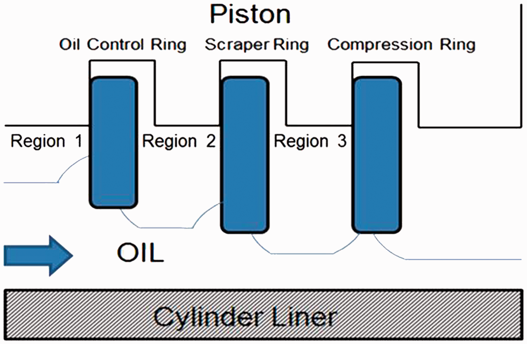
Schematic showing the flow of oil between the rings and liner for a downstroke.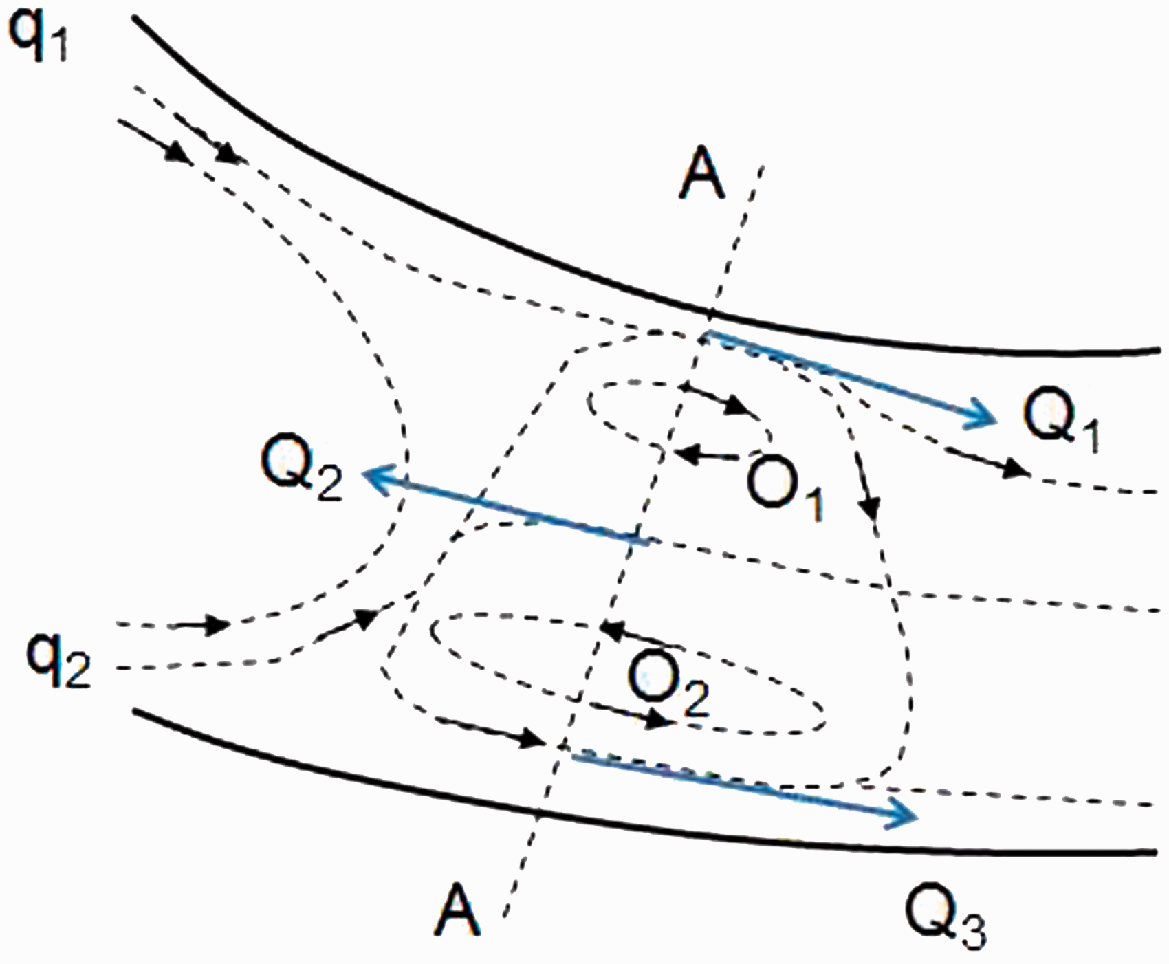
Tipei 30 provided a detailed explanation of the fluid film flow, depending upon the upstream flow dynamics as shown in Figure 3. The supplied fluid flow, q1 and q2, adhere to the surfaces, partially penetrating the load-carrying zone. The centre of the vortices, O1 and O2, lie on the contact normal A–A, which according to the theory of lubrication is the upstream limit for which the fluid film in Navier–Stokes equations can be simplified. Thus, one cannot assume that downstream of A–A the fluid would fill the gap entirely, or indeed neglect the velocity components normal to the surfaces. Using the method expounded by Tipei, it is possible to determine where an inlet boundary condition should be placed, as opposed to assuming an idealised fully flooded inlet.
Experimental studies on the effects of surface texturing in order to tackle starvation have shown that starvation occurs after each reversal, even when the contact is subject to fully flooded conditions. The change of direction makes the cavitated region of the outlet the new inlet region in the subsequent stroke.46,47 It was also observed that the region of starvation can occur for 5% of the stroke. However, this will be dependent upon the viscosity of the lubricant.
Outlet boundary conditions are also affected when modelling piston rings due to the effect of cavitation. The Reynolds (or Swift–Steiber48,49) outlet boundary conditions can be applied, which determine the location of the lubricant film rupture along the entraining x-direction of the contact. Assuming that cavitation occurs in the direction of fluid flow, where the pressure gradient diminishes, the cavitation pressure is taken to be half that of the cavity, although in most cases this is assumed to be at atmospheric pressure. It is also assumed that the lubricant flows between the air cavities, although the effect at the cavity–fluid interface is ignored. Arcoumanis et al.
50
conducted an experiment, which showed that predictions using the Swift–Steiber boundary conditions matched the experimental observations for the most of the engine stroke. Accordingly, the exit boundary conditions become
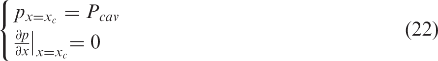
In the current analysis the cavitation pressure,
Prediction of the location of boundary condition at the inlet
The primary focus of the current analysis is the effect of boundary conditions on the generated frictional losses due to starvation. Tipei 30 showed that the justification for two-dimensional Reynolds equation under the continuity of flow condition is only valid for special cases, although it is applicable for practical problems. It was shown experimentally that not all of the lubricant is drawn between the two contiguous surfaces for a given conjunctional geometry (wedge shape), load and speed. In fact, only a fraction of the in-bound lubricant is drawn into the contact.51,52
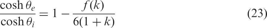
An analytical expression was obtained by Tipei
30
through application of Swift–Steiber boundary condition at the inlet and outlet of the contact (dp/dx = 0 and
Ring pack modelling: Starvation due to oil availability
Starvation occurs due to a physical lack of lubricant at any conjunctional inlet. The cylinder liner can be subdivided into three distinct regions according to the sources of lubricant supply (Figure 4). These are as follows:
Region 1: between the oil control ring positions at the TDC and the bottom dead centre. Region 2: between the scraper ring and the oil control ring positions at the TDC. Region 3: between the compression ring and the scraper ring positions at the TDC.
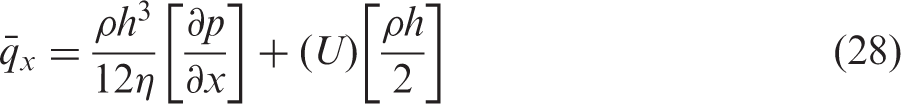
The available oil for a trailing ring is specified by the thickness of a lubricant layer,
Solution procedure
The following solution procedure is undertaken
At any crank angle position, determine which ring is the leading ring and which is the trailing one. For upstroke crank angles the top compression ring is the leading ring, whilst for downstroke motion the scraper ring is the leading ring. Apply Tipei’s conditions to find the inlet and exit locations for the leading ring. Solve Reynolds, film thickness and rheological state equations to calculate the minimum film thickness and friction due to the leading ring. The inlet position depends on the film thickness affected by the position of the stagnation point (i.e. the inlet boundary). There is an intermediate iterative loop to converge for the inlet position and lubricant film thickness. Using the results for the leading ring, the lubricant flow rate and thickness of film left on the free liner surface are determined. Apply Tipei conditions to determine the inlet and exit locations for any trailing ring. The same intermediate loop, as in step 3, is used for step 5. Use step 2 for any trailing ring.
These steps of calculation are carried out at every crank angle position. A simplified version is shown in Figure 5.
Condensed flow chart showing the solution procedure.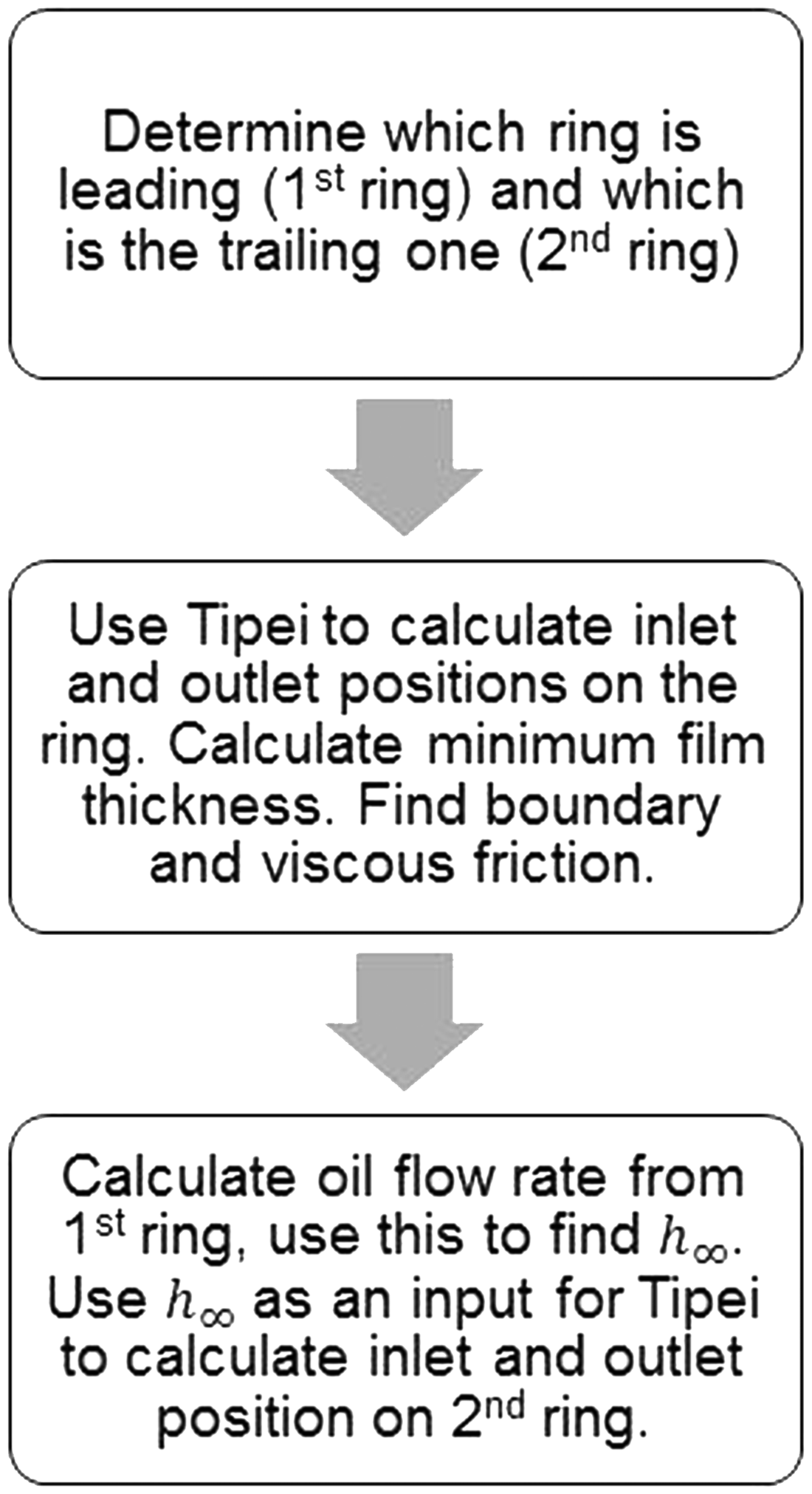
Results and discussion
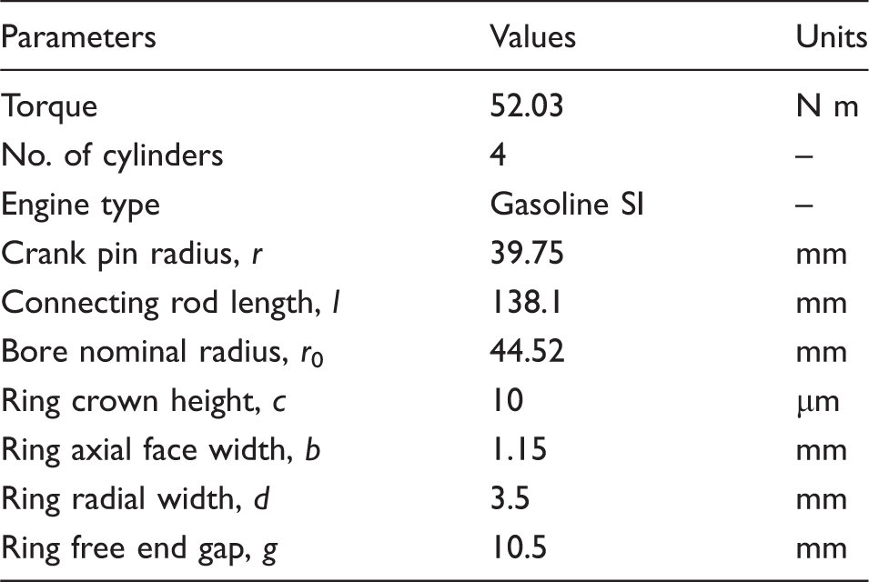
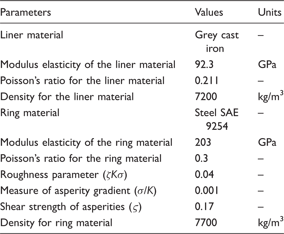
Engine data.
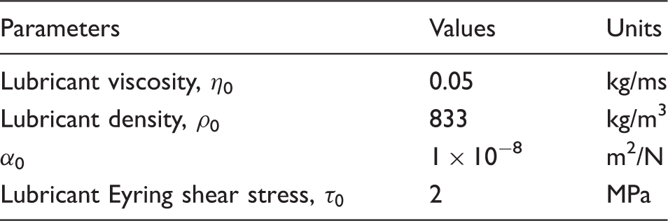
Lubricant properties in atmospheric pressure and 40 ℃.
Material properties and surface topographical parameters.
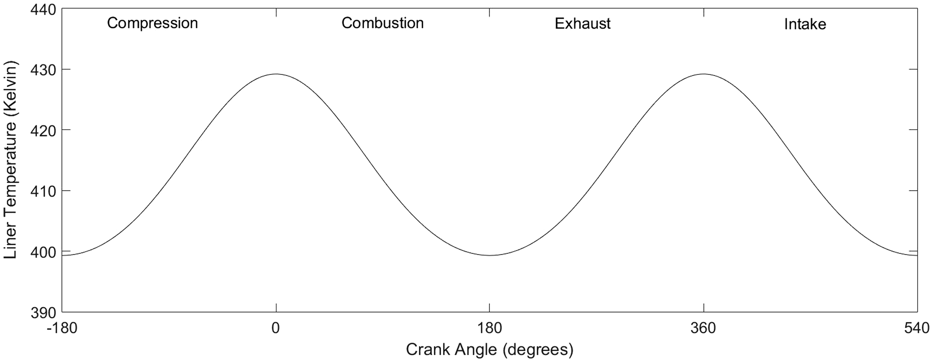
The variation in the minimum lubricant film thickness and total cyclic friction is predicted for both the top compression ring and a scraper ring of the same conjunctional dimensions. The crank angle Combustion pressure. Measured liner temperature.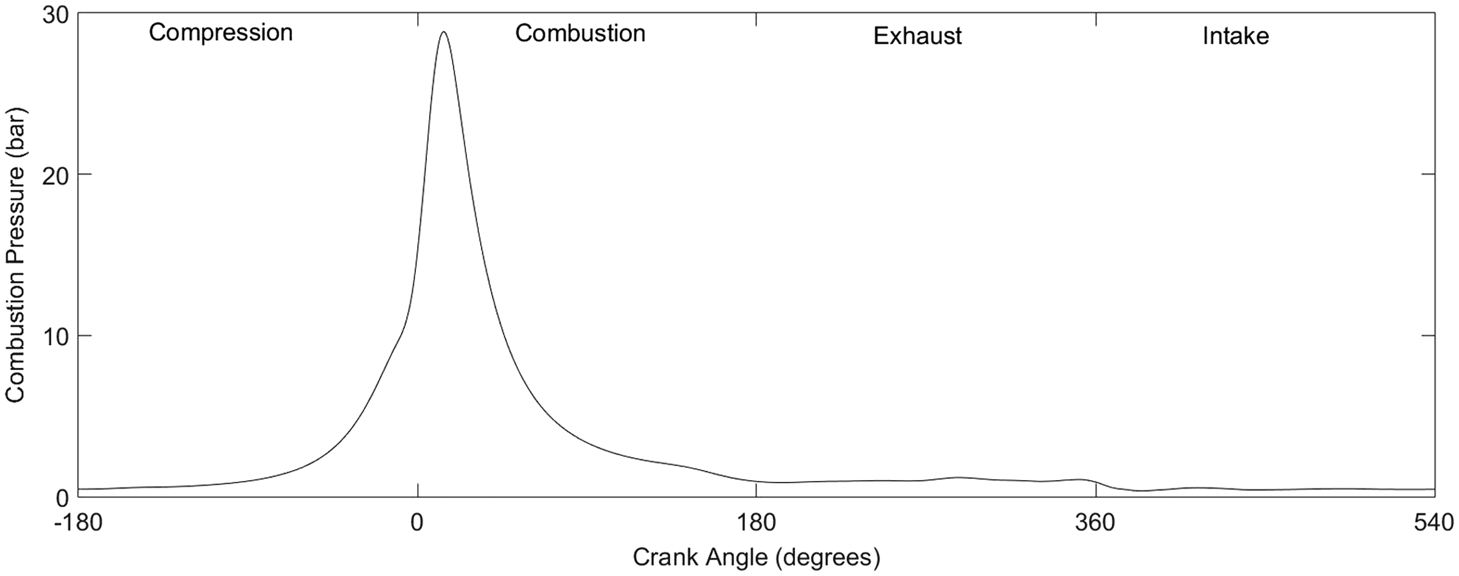
Application of zero reverse inlet boundary flow to the top compression ring
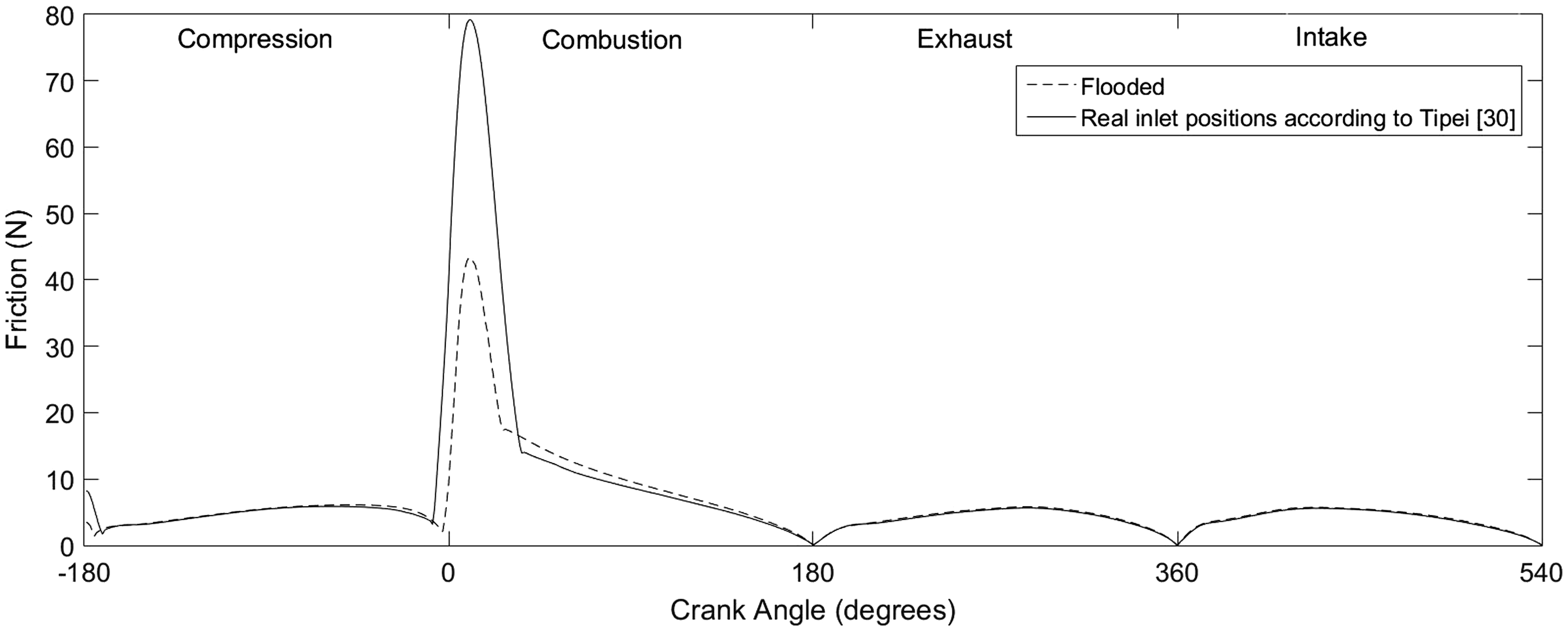
In order to understand the effect of starvation due to inlet counter flow prior to the stagnation boundary, the in-bound flow into the top compression ring–liner conjunction is analysed. Figures 8 and 9 demonstrate that there is a reduction in the film thickness and an increase in total cyclic friction when the zero reverse boundary condition is used. The most significant effect on generated friction occurs at the piston reversal at the TDC, in transition from compression to power stroke. There is an increase of 50% in friction. This is mainly due to an increase in asperity interactions. The straight line in Figure 8 shows the onset of asperity interaction (i.e. Cyclic variation of minimum film thickness. Cyclic total (combined viscous and boundary) friction.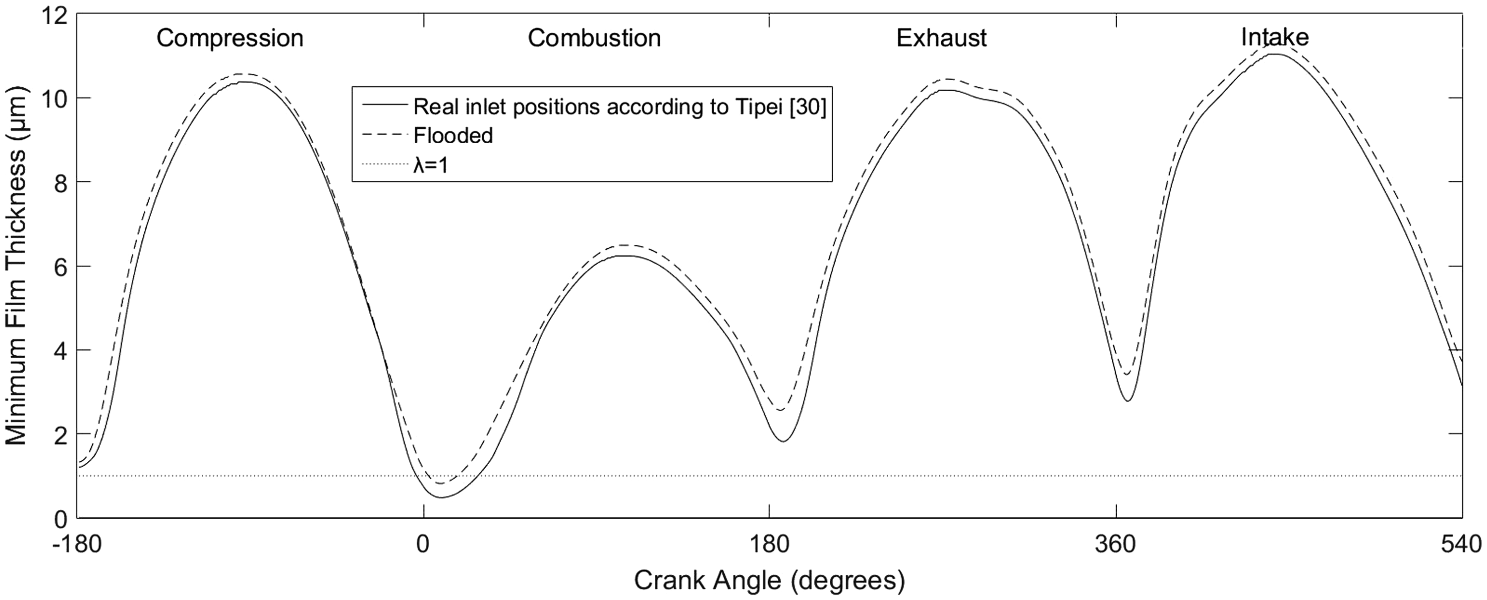
The ring pack model
It is possible to calculate the minimum lubricant film thickness and generated friction for a series of piston rings based upon lubricant availability on the free liner surface. Figure 10 shows the minimum film thickness for the top compression ring and the scraper ring, and the quantity of lubricant film available on the free liner surface Minimum oil film thickness. Cyclic friction.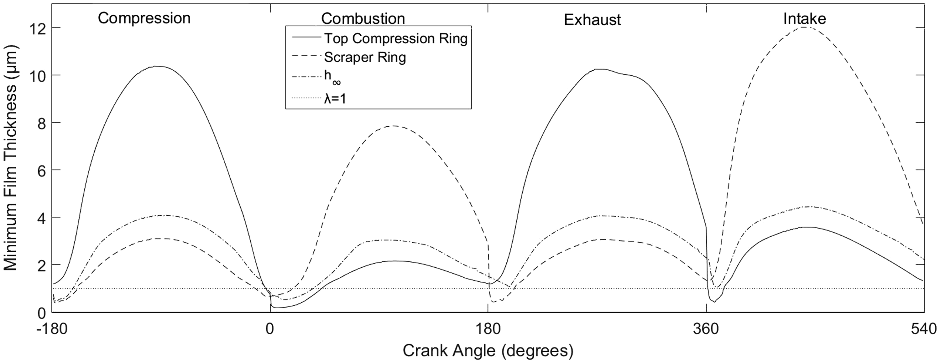
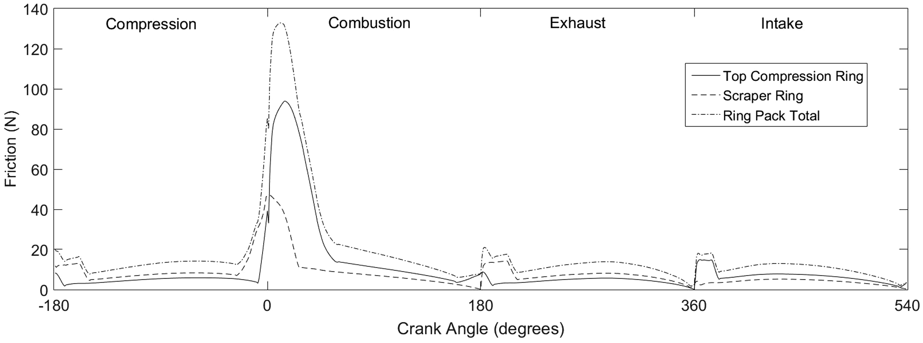
Figure 12 shows the total predicted power loss due to friction in the ring pack. It can be seen that viscous friction plays a dominant role in the compression, exhaust and intake strokes. Thus, an effective way of reducing friction in this conjunction would be to reduce the lubricant viscosity.
54
However, in the combustion stroke there is also a considerable contribution from boundary friction, thus power loss due to a thinner lubricant film and higher asperity interaction inside the contact. This finding conforms to previously reported experiments, where boundary interactions were found to be dominant in the combustion stroke.
27
Total power loss for the ring pack.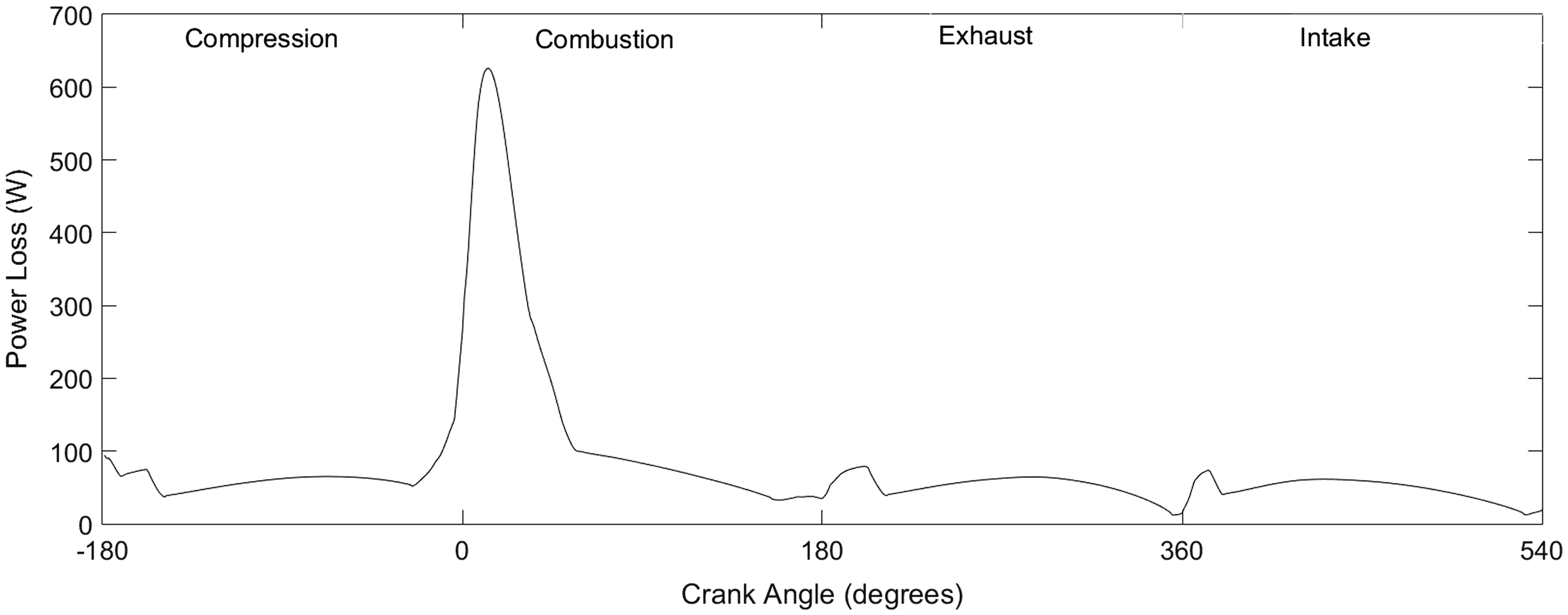
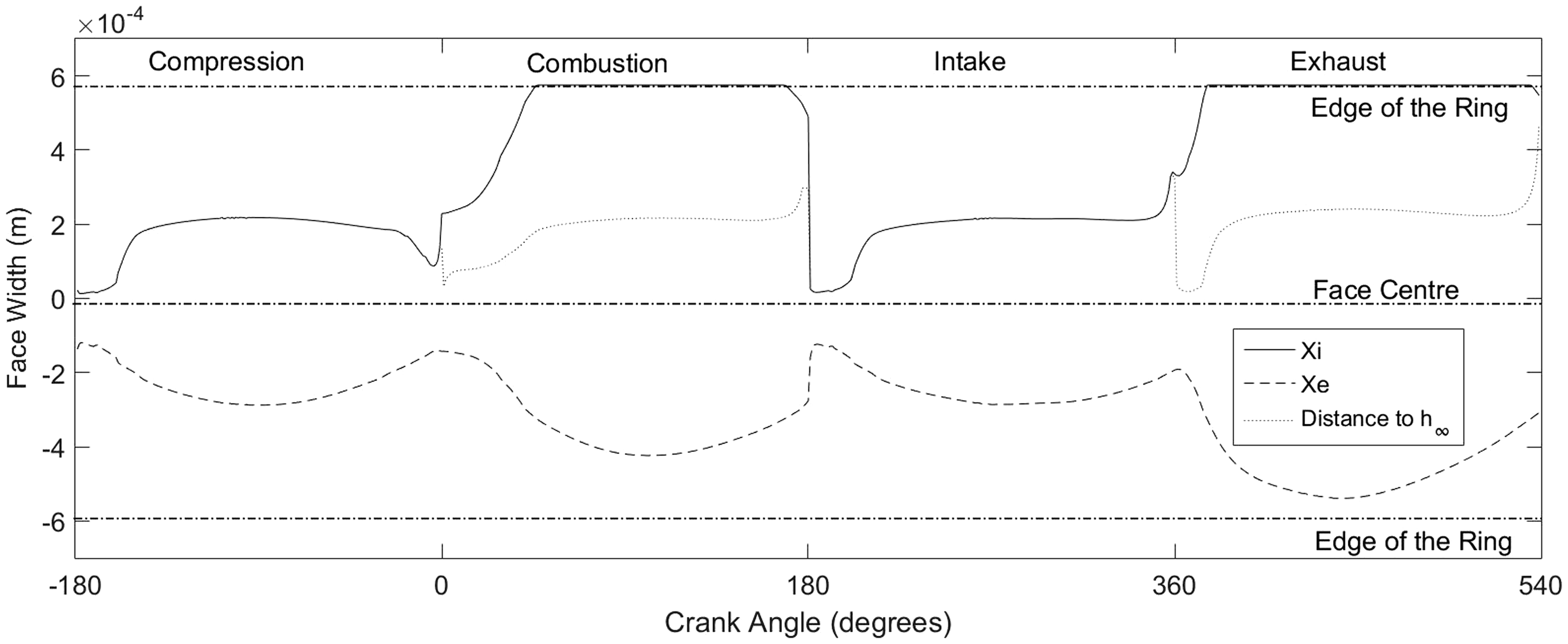
Figures 13 and 14 show the realistic inlet and outlet positions (as opposed to the generally assumed idealised ones) calculated for the top compression ring and the scraper ring, respectively. The dot-dashed lines in each figure represent the top and bottom land of the ring. It should be noted that for the fully flooded case the top or bottom land would be used as the inlet. However, this analysis shows that for both rings in both upstroke and downstroke motions there would be regions with insufficient lubricant availability to warrant an assumed fully flooded inlet.
Inlet and outlet locations of the top compression ring. Inlet and outlet locations of the scraper ring.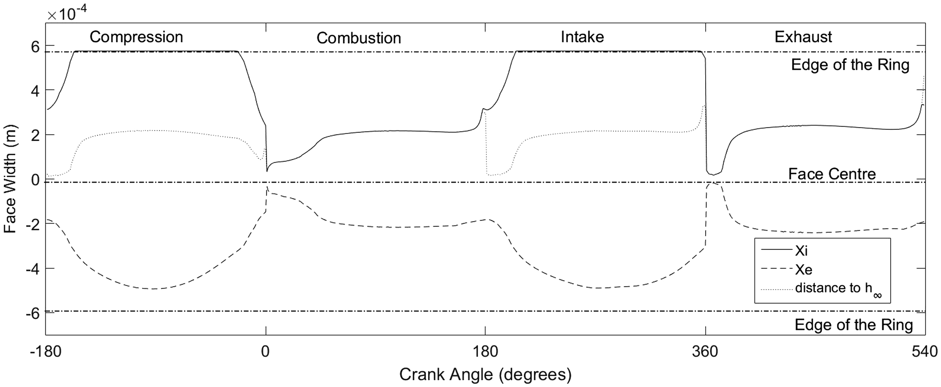
Concluding remarks
The paper presents a two-dimensional model of a piston ring pack comprising of a compression ring and scraper ring capable of predicting the minimum film thickness, friction and total power loss, taking into account two types of starvation. The analysis shows that by calculating the correct inlet and outlet boundary positions the available oil can be determined for system-level analysis of a ring pack, thus tackling both of the main sources of starvation. The first source is due to a physical lack of lubricant (i.e. a starved meniscus), whilst the second source is because of reverse (counter) flow at the conjunctional inlet. Such an approach has not hitherto been reported in literature for the analysis of a piston ring pack. By correct positioning of the inlet boundary at the flow stagnation point, it is shown that there is a reduction in the thickness of the entrained lubricant into the conjunction and thus an increased overall friction.
Footnotes
Declaration of Conflicting Interests
The author(s) declared no potential conflicts of interest with respect to the research, authorship, and/or publication of this article.
Funding
The author(s) disclosed receipt of the following financial support for the research, authorship, and/or publication of this article: The authors would like to express their gratitude to the Engineering and Physical Sciences Research Council (EPSRC) and AVL List for the financial and technical support extended to this research.