
Abstract
Reciprocating and low-speed sliding contacts can experience increased friction because of solid boundary interactions. Use of surface texturing has been shown to mitigate undue boundary friction and improve energy efficiency. A combined numerical and experimental investigation is presented to ascertain the beneficial effect of pressure perturbation caused by micro-hydrodynamics of entrapped reservoirs of lubricant in cavities of textured forms as well as improved micro-wedge flow. The results show good agreement between numerical predictions and experimental measurements using a precision sliding rig with a floating bed-plate. Results show that the texture pattern and distribution can be optimised for given conditions, dependent on the intended application under laboratory conditions. The translation of the same into practical in-field applications must be carried out in conjunction with the cost of fabrication and perceived economic gain. This means that near optimal conditions may suffice for most application areas and in practice lesser benefits may accrue than that obtained under ideal laboratory conditions.
Keywords
Introduction
Energy efficiency is progressively viewed as the most essential attribute for all machines and mechanisms. An important source of energy inefficiency is friction, which may be viewed as an energy sink. Therefore, except for some occasions where friction is crucial for fulfilling certain functions, such as in traction, braking or locomotion, its minimisation is an important design goal. The increasing scarcity of fossil fuels with the associated increase in cost and their adverse effect on the environment are key motivators in the drive to mitigate the effects of friction.
As friction occurs naturally, there have been many attempts since antiquity to minimise the required effort to overcome it, as well as forming an understanding of it. Amontons 1 described the underlying mechanism of friction as the interaction of rough surfaces, independent of their apparent area of contact. Later Euler 2 provided the first definition for the coefficient of friction and its relation to the state of motion. Coulomb 3 confirmed the findings of Amontons and Euler in distinguishing between static and kinetic states of friction.
The Amontons–Coulomb fundamental laws imply friction as an inherent property of surfaces; their topography and mechanical properties. However, by the turn of the 20th century it became clear that these fundamental laws do not apply to real surfaces which are invariably wetted either by an applied film of lubricant or their contact tribo-chemistry leads to the formation of an oxide surface layer when exposed to normal atmosphere.4,5 In fact, nature itself has made use of rough surface topography in the presence of a fluid to enhance load-carrying capacity and also reduce friction. One example is the combined action of fairly rough cartilage covered surfaces and synovial fluid in the endo-articular joints of all vertebrates through the mechanism of micro-elastohydrodynamic lubrication. 6 Therefore, nature’s own choice seems to run contrary to Amontons–Coulomb laws of friction. The perspective appears to be that of surface-lubricant as a system.
At the diminutive physical scale of surface asperities, boundary-active fluid species can adsorb to surface features, as well as being entrapped and entrained into the asperities’ interspatial valleys.7,8 Therefore, unlike the idealised dry friction, wet rough contacting surface topography can actually aid lubrication and reduce friction. The realisation of this point has gradually led to the introduction of engineered textured features on sliding surfaces. In fact, the use of various surface texture forms has been shown to improve tribological performance in Costa and Hutchings, 9 Etsion and Burstein 10 and Ronen et al. 11 among others. Numerical and analytical analyses have also led to the determination of ‘optimal’ texture form, geometry and distribution for sliding contacts, for example by Rahmani et al.12,13
The introduction of surface textures is most effective in circumstances when poor contact kinematics such as stop-start, reciprocating motion or low relative surface speed leads to lack of lubricant entrainment into the contact. These circumstances lead to boundary regime of lubrication. There are many such instances in various machines. For example, in internal combustion engines, piston motion reversals at top and bottom dead centres are accompanied by the momentary cessation of lubricant entrainment into the piston skirt and ring pack. Use of surface texturing, introduced in the vicinity of piston reversals, has shown to reduce frictional power loss, both analytically, 14 as well as through testing by Etsion 15 and combined studies by Rahnejat et al. 16 Other investigations include that of Yu et al. 17 for the effect of texturing during sudden changes of speed in mechanical face seals and that of Pettersson and Jacobson 18 for reciprocating ring/roller contact in hydraulic motors. It is suggested that the cavities formed by the introduced micro-structures can act as lubricant reservoirs or encourage micro-wedge effect (micro-hydrodynamics) for lubricant entrainment.15,16,19,20 The micro-hydrodynamic effect is analogous to the pressure perturbations in natural mammalian joints, 6 which improve the contact load-carrying capacity. 13 In fact, aside from this localised effect, surface textures have also been shown to expand the region in which hydrodynamic lubrication occurs. 21
The geometric form and distribution of texture features have also been investigated by many authors. The form largely depends on the method of manufacture/fabrication such as vibro-rolling, 22 ion reactive etching, indentation,23,24 abrasive jet machining, 25 photo-lithography, 26 anisotropic etching 26 and laser surface texturing (LST),15,16,27,28 the last of which has gradually become the process of choice. This is because LST lends itself to a greater degree of automation as well as a better control for application to curved surfaces such as cylinder liners 16 and piston ring face-width, 29 as well as fabrication of different texture geometries. Ryk et al. 29 introduced partial texturing on the compression ring’s flat chamfered face-width, noting this to be the most effective in reduction of friction in their engine tests. On the other hand, Howell-Smith et al. 30 noted that whilst texture features can act as reservoirs of lubricant and aid reduction of friction, they may also cause oil loss in piston cylinder system as well as breach the sealing function of the compression ring. This suggests that it is better to introduce these features on the stationary cylinder bore/liner in the vicinity of the top ring reversal. Their results show that indented liners with features resembling the cross section of a Vickers tool provide optimum performance in a high performance fired engine. However, laser-etched crescent shapes (analogous to a chevron) are more practical and cost effective to produce on curved concave surfaces and perform nearly as well as the indented features. Costa and Hutchings 9 also investigated a range of surface texture shapes, including chevrons under sliding conditions, where the largest improvement in generation of a hydrodynamic film was observed.
The current study combines numerical analysis and experimental measurement of chevron-shaped surface textures under sliding conditions. A numerical parametric study of the chevron shape design has been carried out, using improved chevron textures and distribution. The results are validated experimentally with the use of a reciprocating precision sliding bench-top test rig. The aims of the investigation are two-fold; firstly to further the fundamental knowledge of surface texturing and secondly, to demonstrate the design and development process for a suitable surface texture which can be used in real engineering applications.
Reciprocating sliding contact
Reciprocating or low-speed sliding contacts are subject to a transient regime of lubrication. Poor tribological conditions invariably occur at contact reversals, where lack of any relative sliding motion of the mating surfaces results in the momentary cessation of lubricant entrainment into the contact zone. This leads progressively to a greater number of ubiquitous asperities on the counterfaces coming into contact, leading to mixed or boundary regimes of lubrication. Such conditions are quite prevalent in many forms of contact, such as piston-cylinder system. 31 Sliding contacts operating in the mixed or boundary regimes of lubrication experience increased frictional power loss when compared to fluid regimes of lubrication such as hydrodynamics, thus the reason for the various applications of texturing to the contiguous surfaces,14–16 all of which have shown 2–4% reduction in in-cylinder frictional losses, ascertained through improved BMEP. A more direct method of measurement would be preferred as well as linking any reduction in friction to the prevailing regime of lubrication. A direct in situ method of measurement for cylinder applications has been through the use of a floating liner, which is dragged by the reciprocating piston relative to the bore surface by an infinitesimal amount. The floating liner is flexibly mounted to the cylinder bore through intervening load cells which directly measure friction. Such arrangements have been reported by Furuhama and Sasaki 32 and Gore et al. 33 for engine testing conditions, although not including surface textures. However, friction in the engine cylinder is dependent on the many physical interactions arising from variations in the combustion chamber pressure, heat generation and thermo-elastic deformation of contiguous solids. Therefore, a fundamental scientific study is preferred to focus on the effect of surface texturing under controlled laboratory conditions, at least in the first instance, prior to engine applications. Hence, development of a precision reciprocating slider on a floating base-plate analogous to a floating cylinder liner would be advantageous. The focus of this study is mixed lubrication conditions at low sliding speed, whilst traversing a textured region. These conditions were noted for the engine case in Rahnejat et al., 16 where the textured area was provided at the top compression ring reversal point.
A reciprocating slider bench test rig has been developed and described by Chong and De la Cruz et al.
34
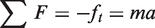
(Figure 1). A sliding thin strip slider with a face-width profile, representative of an engine compression ring is loaded against the flat plate, with a thin layer of lubricant applied. The plate is mounted upon precision, low friction bearings and is allowed to float, when dragged by the sliding strip. An electric motor is directly coupled to the loaded sliding strip via a low friction and almost backlash-free lead-screw drive. Piezo-resistive force sensors, positioned at either ends of the plate directly measure the inertial force of the floating plate, which is due to the generated contact friction as
The reciprocating slider test rig.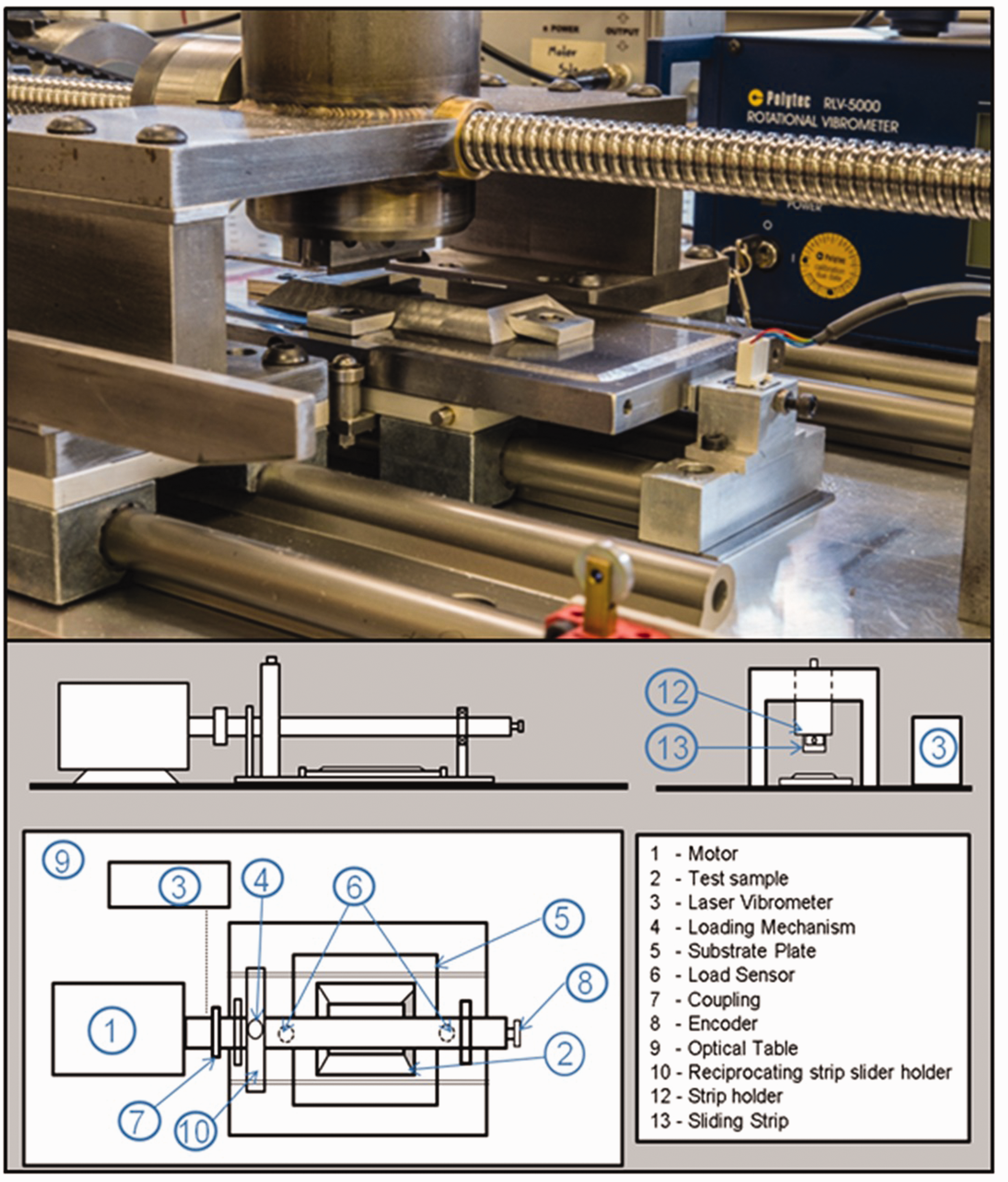
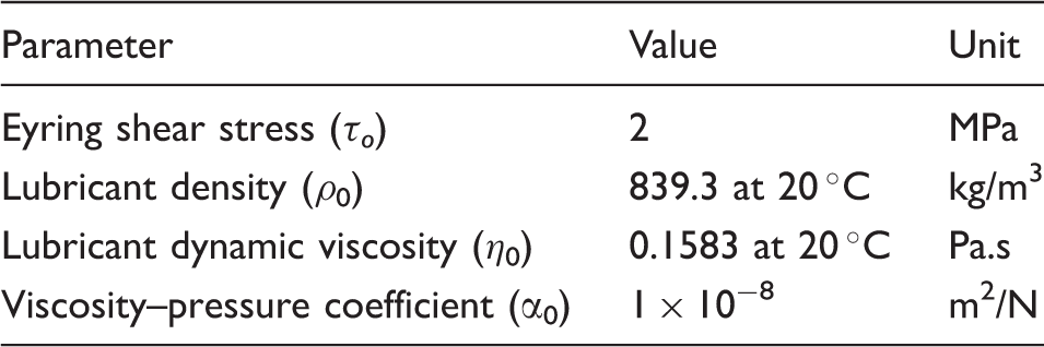
Base oil data.
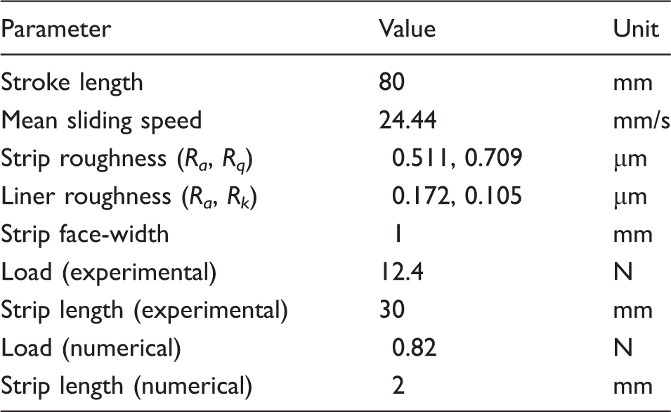
Strip and floating plate data.
Laser surface texturing
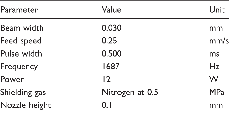
Chevron-shaped textures were laser etched onto a region of the floating plate as shown in Figure 2. A SPI 50 Watt fibre laser was used to create the chevrons. The laser parameters are provided in Table 3.
Measured 3D image of chevrons produced with the fibre laser. SPI fibre laser data.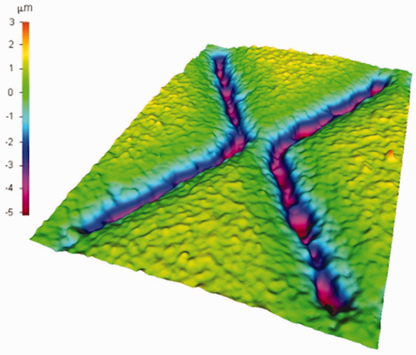
After the LST process, the plate is polished for a short period of time to remove any residual splatter or debris protruding from the surface. Figure 3 shows an image of typical laser-etched chevrons obtained through the Alicona infinite focus microscope with a measurement resolution of 1 nm.
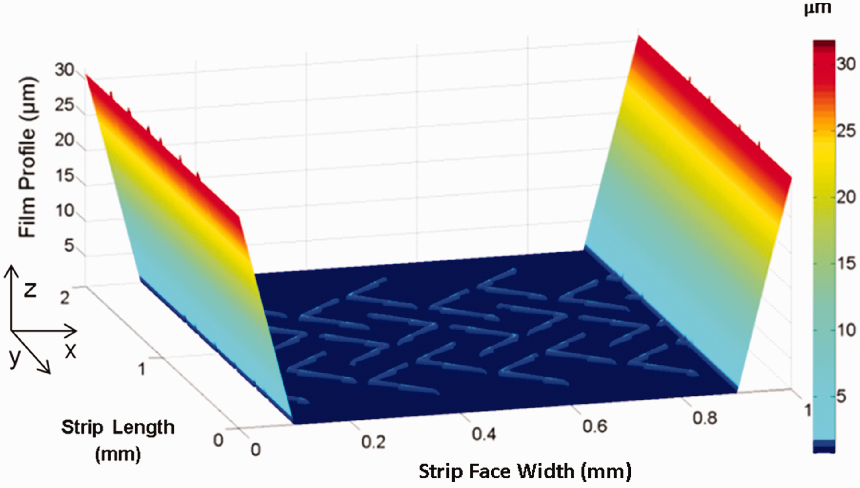
Image of a chevron and corresponding chevron depth profile.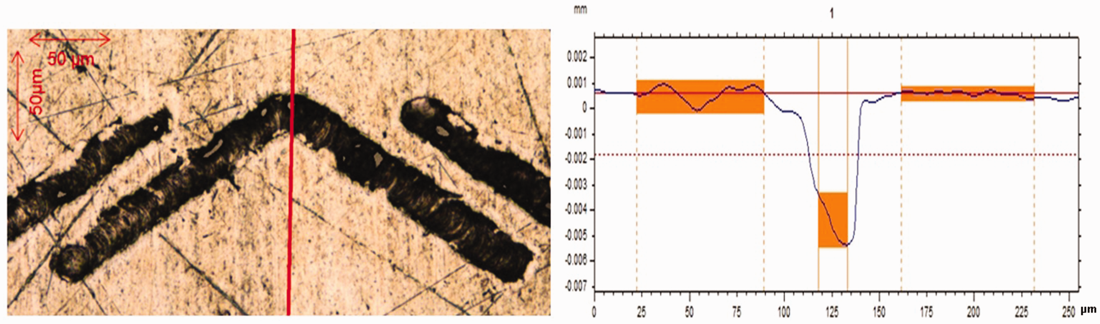
The surface roughness of the plate and the flat ring were measured (Table 2), as well as the chevron depth and the sliding strip’s face profile. The chevrons have a thickness-to-depth ratio of 0.11 (representative of an optimised ratio as demonstrated by Etsion and Sher 28 ), although some variation in the chevron depth is produced in the LST process.
The LST produces chevrons with a cross-sectional profile similar to that of a parabola (Figure 3), and are therefore, modelled accordingly.
Numerical analysis
Prior to laser texturing of any form, geometry and distribution of chevron-type textures onto the surface of the sliding plate, it is important to undertake numerical analysis of the contact. This is due to the fact that there can be numerous combinations of geometrical parameters and distribution patterns with different outcomes. Therefore, the numerical analysis can provide the range of values that it is expected to yield desired performance from the textured surface. This can be carried out at low cost in comparison to the manufacture of a sufficiently varied set of samples. Then, a parametric study can be undertaken to strive to optimise the texture pattern and form with respect to minimisation of friction. A limited number of cases, advised through numerical simulation, can then be physically tested.
Numerical method
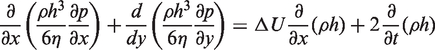
The reciprocating sliding contact is subjected to a transient regime of lubrication. Lubricant is entrained into the gap between the slider and the floating plate through the hydrodynamic wedge effect and carries the net contact load. At low speed of entraining motion or with cessation of sliding at or in the vicinity of motion reversal, there is insufficient film thickness. The film can then be interrupted by the interaction of counterface asperities, which also carry a small portion of the applied load, but contribute disproportionately to the generated friction. To obtain the hydrodynamic load-carrying capacity, the generated hydrodynamic pressures are obtained through solution of Reynolds equation. Assuming no side leakage flow in the transverse direction along the length of the thin strip slider, Reynolds equation becomes
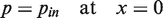
A fully flooded inlet is assumed as the surface of the floating plate is provided with a layer of free surface film ahead of the sliding contact as shown in Figure 4. In the case of an engine, a starved inlet boundary can be encountered, particularly in the upstroke motion of the piston as a free surface film may not exist on the hot surface of the bore/liner.
Contact configuration.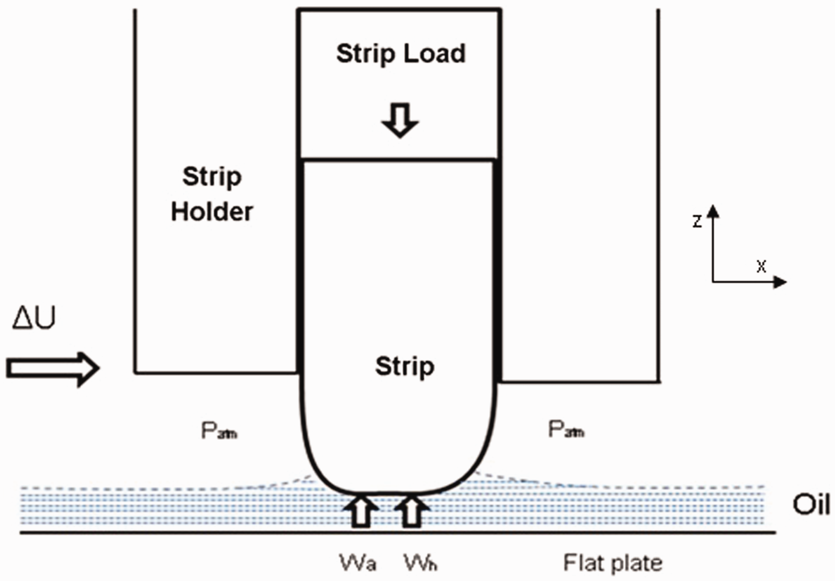
The outlet boundary conditions are those of Swift
37
–Stieber
38
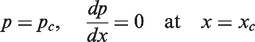
(Reynolds’ exit boundary condition) with an assumed atmospheric vaporisation pressure of the lubricant at the film rupture point. The current boundary conditions do not take into account the effect of cavitation beyond the lubricant film rupture boundary. Cavitation can affect the load-carrying capacity of the contact. Elrod’s
39
cavitation method can be used instead of the Swift-Stieber boundary conditions to take this issue into account. This imposes continuity of Couette flow beyond the film rupture point. Even a better approach is to use a mass-conserving multi-phase approach with open exit boundary conditions such as that described by Ausas et al.
40
who used this approach for the study of textured surfaces in journal bearings. They showed that cavitation plays an important role in load-carrying capacity and generated friction. Shahmohamadi et al.
41
also used this approach for the study of lubrication for piston compression rings but for untextured surfaces and with the inclusion of thermal effects. Shahmohamadi et al. showed that in the case of ring-bore contact, cavitation occurs mostly at mid-stroke piston positions where the results of their computational fluid dynamics analysis diverged from that with non-mass-conserving approaches. In a detailed study of various boundary conditions in piston compression ring conjunction, Arcoumanis et al.
42
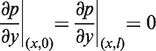
concluded that the Swift–Stieber boundary condition agreed better with their experimentally measure conditions. Based on these finding, the current analysis uses the Swift–Stieber exit boundary conditions. The inlet pressure at the front face of the strip is also set to the atmospheric pressure. Only a segment of the whole strip’s width in the y-direction (direction of lubricant side-leakage) is included in the model to keep the computational time to an acceptable level. The applied load for the section of the contact considered for numerical analysis is shown in (Table 2). Hence, the computational boundary conditions are
The generated pressures at such low loads are insufficient to induce significant piezo-viscous action of the lubricant. This is also noted by other investigators.35,36 For completeness of the method, piezo-viscous effects are retained. Furthermore, due to short testing times, isothermal analysis is undertaken at the laboratory temperature of 20 ℃ as explained in the “Experimental results” section.
Therefore, for an isothermal solution only the piezo-viscous behaviour of the lubricant needs to be considered. According to Roelands
43
where p is the hydrodynamic pressure
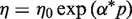
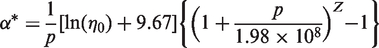
And the pressure viscosity index is
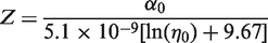
The lubricant viscosity at atmospheric pressure 
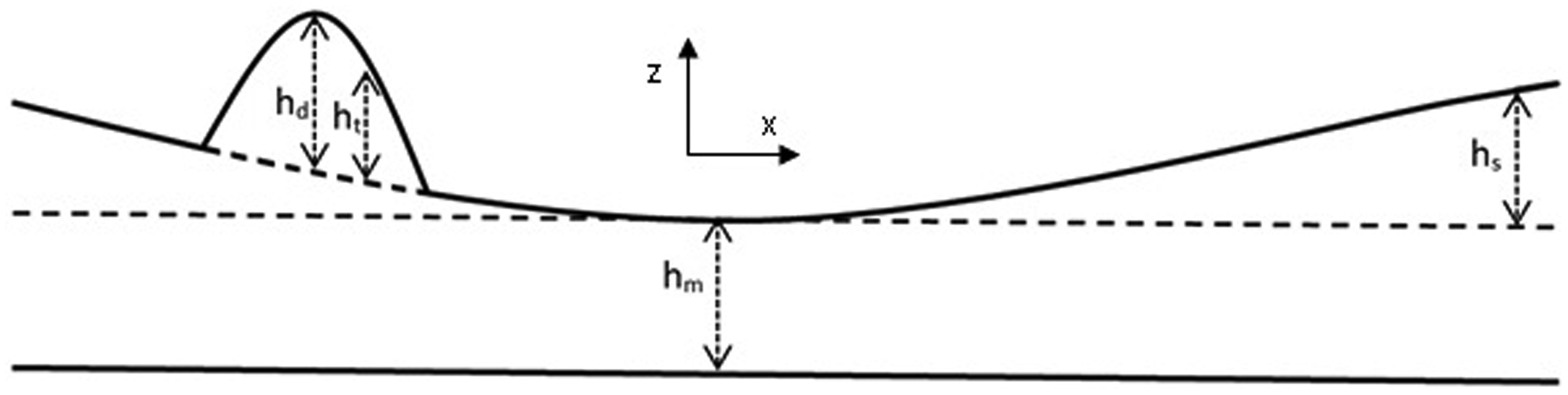
The film shape is described as (Figure 5)
Film shape for rough contact with surface texture.
Face profile of the sliding strip
The strip’s face-width profile hs is measured, and is modelled as only varying in the x -direction (direction of entraining motion). The axial strip profile is an important factor for the entrainment of the lubricant into the conjunction through hydrodynamic inlet wedge effect. 6 Therefore, sliding rings often have profiled edges such as small relief radii or chamfers.
For the purpose of numerical analysis, the strip profile was measured using an Alicona Infinite Focus Microscope; with a measurement resolution of 1 nm. From the measurements taken, the strip slider profile in Figure 6 is created using the following set of equations
Film shape with chevrons.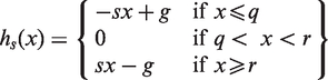
Numerical reconstruction of laser textured chevrons
The surface features are modelled so that their inclusion angle, the perpendicular (length), width and thickness can all be readily altered. These are based on the measurements using the infinite focus microscope. Additionally, inter-spacing between chevrons in a row, y (in the transverse direction) and the separation between rows of chevrons, x (in the direction of sliding) were taken into account, as well the commencement and termination points of the textured region.
The laser surface texturing process produces a chevron with a cross-sectional profile similar to that of a parabola (Figure 3). Therefore, the chevrons were modelled with a parabolic profile as shown in Figure 7.
A schematic of a chevron-based pattern.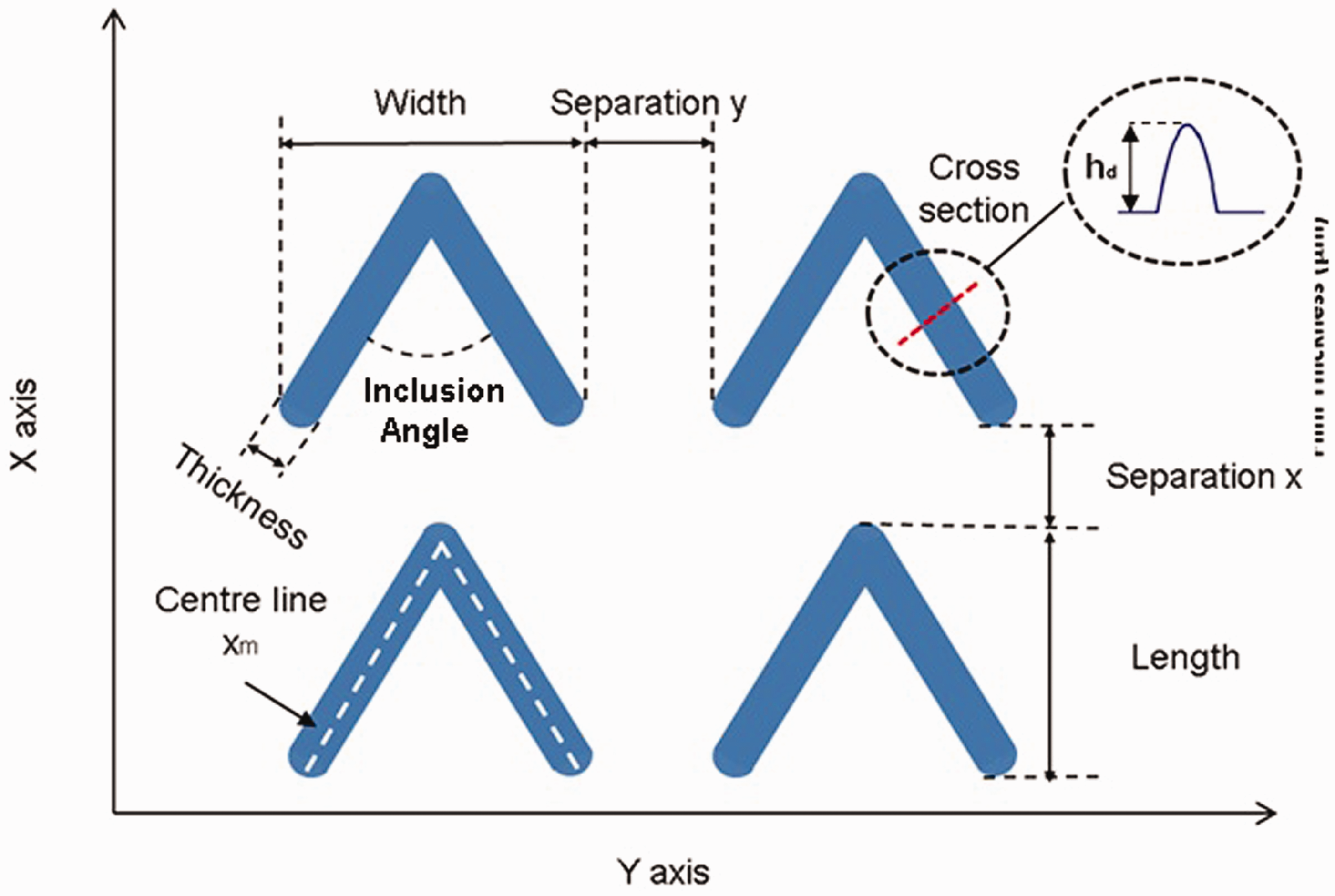
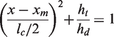
If lc is the thickness of a chevron, hd its depth at its centre line location and xm the position of the centre-line of the chevron cross-sectional width, then a chevron profile can be described as
Contact forces
The thin sliding strip is subjected to an applied load F. This force is opposed by the generated contact force contributions as a result of hydrodynamic pressures and the share of load carried by direct asperity interactions, thus
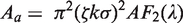
The share of load carried by the asperities can be written as
46
The dimensionless group 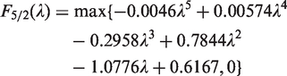
Greenwood and Tripp
46
model is applicable to surfaces with Gaussian distribution of asperities. For such surfaces the statistical skewness parameter
Method of solution
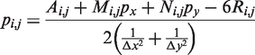
Reynolds equation is discretised using finite difference method, including density and viscosity as functions of generated pressure for the sake of completeness of the method, although the generated hydrodynamic pressures are insufficient in this instance to significantly alter the lubricant rheological state. Thus

The relaxation factor γ is problem-dependent and an optimum value which provides rapid convergence is usually obtained after some numerical tests.
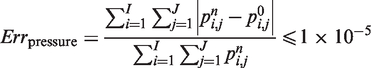
Convergence criteria
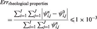
A two stage convergence process is sought. The first criterion is based on the convergence of generated hydrodynamic pressures and the lubricant rheological state as
Also
The second criterion is load balance for instantaneous quasi-static equilibrium, where the contact load must equate the applied load to the sliding strip
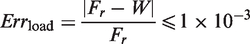
If this criterion is not met, then the minimum film thickness is adjusted as
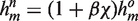
Finally, a typical analysis cycle requires an initial guess as the nominal minimum clearance.
Friction and power loss
In the mixed regime of lubrication, anticipated in the case of contact of the sliding strip against the flat floating plate, two sources contribute to friction; viscous shear of the lubricant entrained into the conjunction and any direct interaction of counterface asperities.
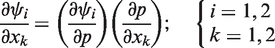
At any time the viscous shear of a lubricant film h can be obtained as:
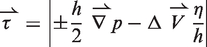
The gradient is defined as 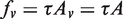
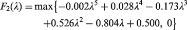
Under the mixed regime of lubrication, boundary friction must also be taken into account.
It is assumed that boundary friction comprises two contributions; one is as the result of direct contact of asperities in the form of their adhesive junctions, which must be broken in order to sustain the sliding motion. If the pressure-induced shear strength of asperities is ξ, then the direct asperity friction is obtained as: 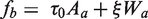
For a ferrous oxide layer
50
Thus, the total friction is obtained as

The total power loss from the conjunction friction is

Results of numerical analysis
Figure 8(a) and (c) shows the pressure distribution for the contact of the thin strip sliding on an un-textured surface and that for a textured surface with chevron features, respectively. Pressure perturbations are evident in the case of the latter, with magnitudes well in excess of the average pressure of 0.15 MPa. These perturbations are as the result of micro-hydrodynamics, induced by the wedge effect at the inlet to each chevron feature as shown in Figure 8(d), which is not evident in the case of the nominally smooth plate (Figure 8(b)). The initial pressure spike at the contact inlet in both cases is caused by the pressure-induced Poiseuille shear flow with the commencement of entraining motion. There is a less pronounced Poiseuille shear at the contact entrance in the case of the textured surface on the account of a shallower pressure gradient due to a larger volume of lubricant. Note that in the case of the untextured surface, the viscous pressure falls gradually back to the atmospheric value at the diverging section of the strip as the profile of the central portion of the strip is flat and hence there would be no contribution due to any changes in the conjunctional profile as is the case for a parabolic profile.
6
Pressure distribution and film shape for smooth (untextured) and textured surfaces.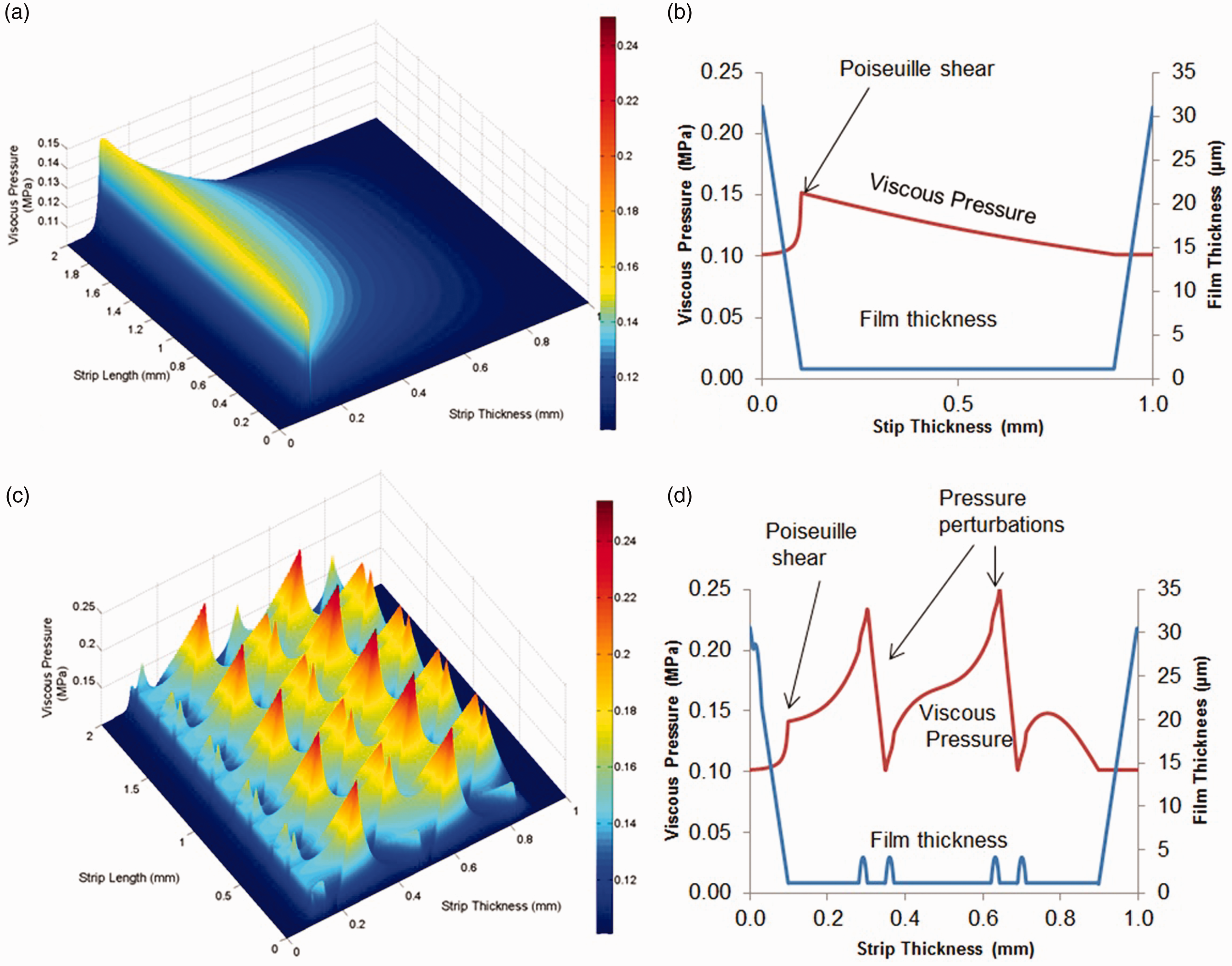
The results in Figure 8 confirm the enhanced load-carrying capacity of the contact with the introduced textured features in almost the same manner as that noted for rough articular cartilage. 6 The pressure distribution in Figure 8(d) is as the result of combined micro-hydrodynamics of individual chevrons as well as the effect of their collective effect. This collective effect of texture forms; chevrons or dimples, is as the result of interactions of their individual micro-hydrodynamics as noted by Brizmer et al. 52 Therefore, the distribution and spatial disposition of the textures as well as the geometry of individual features play an important role in lubricant film formation, load-carrying capacity and generated friction, a parametric study of which is an important undertaking.
Numerical parametric studies
Test matrix for parametric study.
The first parameter considered is the chevron depth. Feature depth has been reported as a key parameter by Ryk et al. 53 The thickness of chevrons is also considered, so that the reported ‘optimal’ height-to-width ratio reported by Ronen et al. 11 can be investigated. It has also been reported by Etsion et al. 54 that the texture density has a significant effect on the tribological performance of the contact. The chevron inclusion angle is also considered to be of interest for the investigation. In effect, chevrons represent a form of cross-hatched surface which is often a process of choice for cylinder liner technology. Spencer et al. 55 have shown the influence of cross-hatch angle to the horizontal (direction of side-leakage flow) to be optimum at 28°–30°.
The distribution or the pattern of the chevrons was also deemed worthy of investigation. A study by Wakuda et al. 25 indicated that the surface texture distribution can affect the tribological properties of the contact.
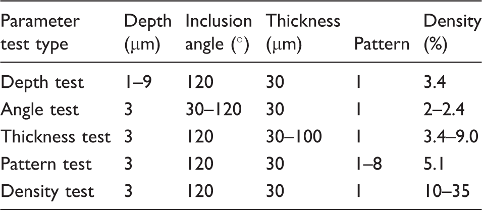
The improvement in friction for a range of the chevrons with different depths is shown in Figure 9(d). The chevron depth has a clear effect on the percentage reduction in friction. A depth of 3 µm indicated the maximum predicted friction reduction. Table 4 shows that these analyses were carried out with a chevron thickness of 30 µm, representing a height-to-width ratio of 0.1.
Results of numerical parametric studies.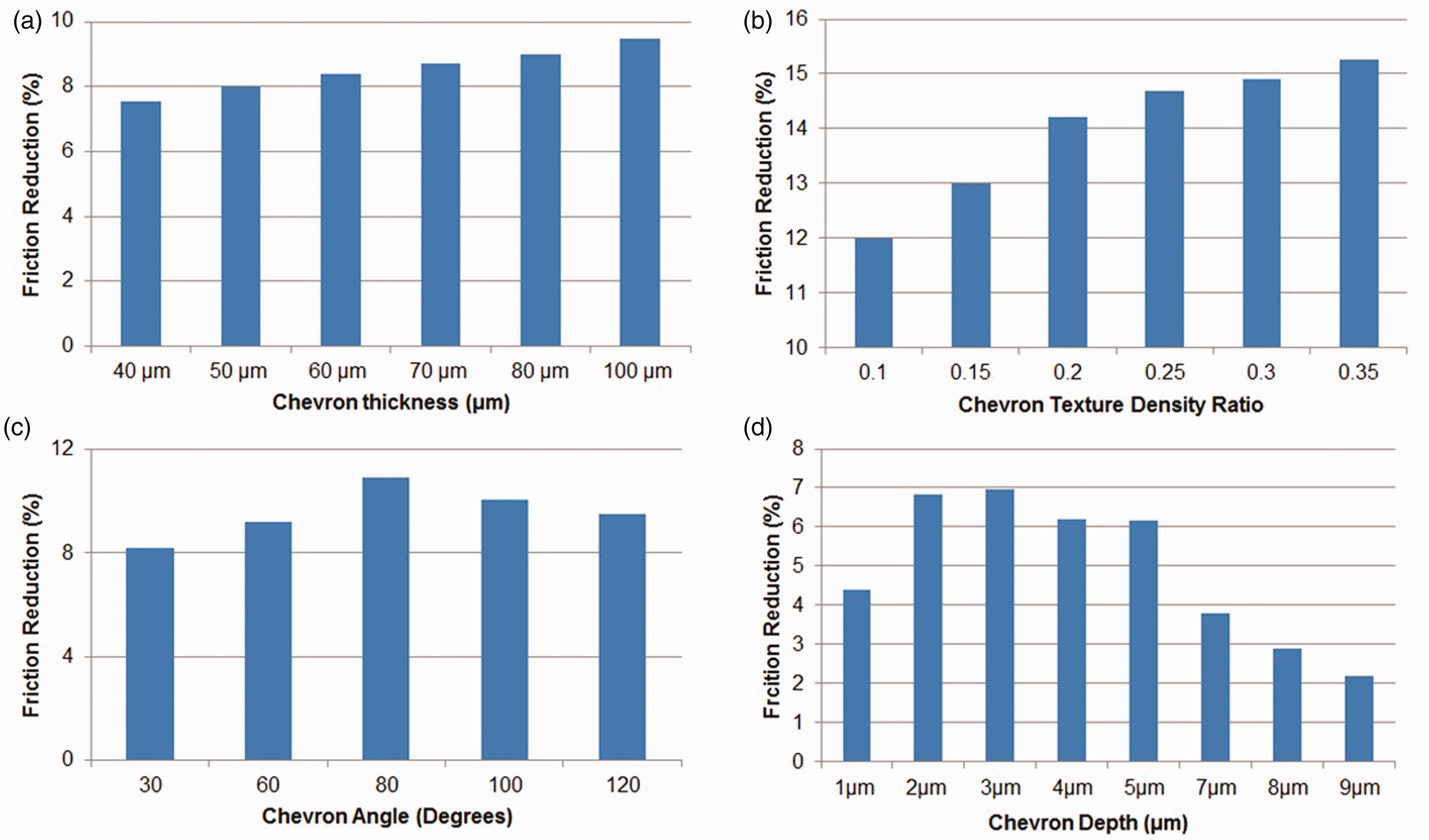
The results for the variation of chevron thickness are also shown in Figure 9(a). The chevron depth was kept at 3 µm for all other analyses. Therefore, the depth-to-thickness ratio only varies in the range: 0.03–0.075.
The effect of chevron inclusion angle is also presented in Figure 9(c). An angle of 80° was found to give the greatest reduction in friction. If chevron texture is to be regarded as being analogous to the usual cross-hatch honed cylinder liner surfaces, then the equivalent cross-hatch angle (measured with respect to the direction of side leakage, y) would be 50° in this case. The analysis by Spencer et al. 55 for the case of cross-hatched cylinders indicated an overall better performance for a cross-hatch angle of around 30°. However, this is dependent on the sliding speed and the depth of the grooves. Furthermore, the current analysis assumes a nominally smooth land/plateau between the chevron features, which is not the case in Spencer et al. 55 A more detailed analysis, including the effect of surface roughness would be required.
As well as the individual chevron properties such as the chevron depth, thickness and inclusion angle, there are also other group-type parameters of interest such as the texture density and pattern. Group parameters are defined as properties which are dependent on a combination of two or more chevrons. The next part of the parametric study is concerned with these group parameters and their effects upon generated friction. Increasing the texture density leads to a greater improvement in friction. In applications such as the piston compression ring–cylinder liner contact, blow-by is a real problem. Increasing the texture density could increase the amount of lubricant passage through the ring and thus contribute to blow-by, power loss or lubricant degradation. Therefore, one should be cautious when applying textures with a high density to a surface in such applications.
The results in Figure 9(b) show that chevron density has a key effect on the percentage improvement in friction. As the chevron texture density increases the generated friction is reduced as it would be expected because of a larger reservoir of lubricant entrapped. The textured density is limited by the chevron shape and size.
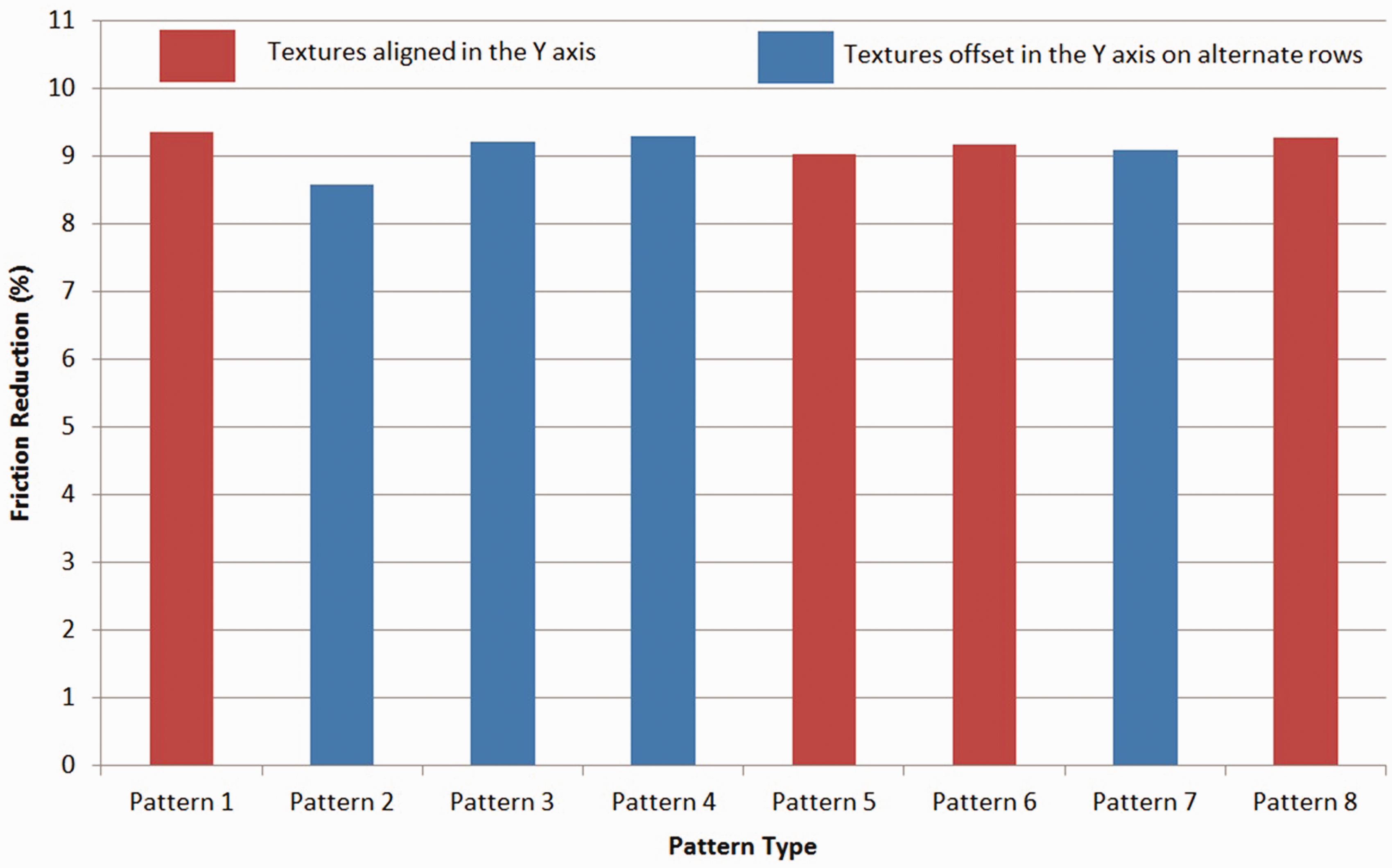
The pattern of the chevrons on the plate can also be varied in many ways. The range of patterns to model can of course be almost in-exhaustive. However, to fit within the parametric study it was decided to vary the orientation of the chevrons with respect to the direction of sliding as well as any row of chevrons’ staggered with respect to a preceding row by half of a chevron’s length. Figure 10 shows eight different patterns modelled. Pattern 1 corresponds to that presented by Costa and Hutchings.
9
As can be seen, all patterns comprising individual chevrons of identical geometrical attributes promote micro-hydrodynamic effect as already noted and described in the case of Figure 8(c), but not in a similar overall manner under the same operating conditions (load and sliding speed). The position of the strip width of 1 mm is also shown in all the figures. Three particular patterns; identified as 1, 4 and 8 in Figure 10 provide an improvement in friction in comparison with the others (Figure 11), although the difference in friction between all the patterns is less than 1%. This small difference, however, may be regarded as quite significant if it can be attained for applications such as compression ring-to-cylinder liner system. Pattern 8 replicates the counter-pose of successive rows of chevrons, with a preceding row facing the direction of sliding motion whilst the following row opposes the same. The philosophy behind these counter-posing rows of chevrons is that the one ahead of the sliding strip would form a convex meniscus directing the entrainment flow to the centre of the contact, whilst the other at the rear of the contact would contain the otherwise outward wake flow due to any side leakage. This pattern was used with curvilinear chevrons by Howell-Smith et al.,
30
where a full numerical analysis and engine test data showed 2–4% friction reduction over a range of engine running conditions.
Chevron textured patterns and micro-hydrodynamic effect. Predictive studies for various textured patterns in Figure 10.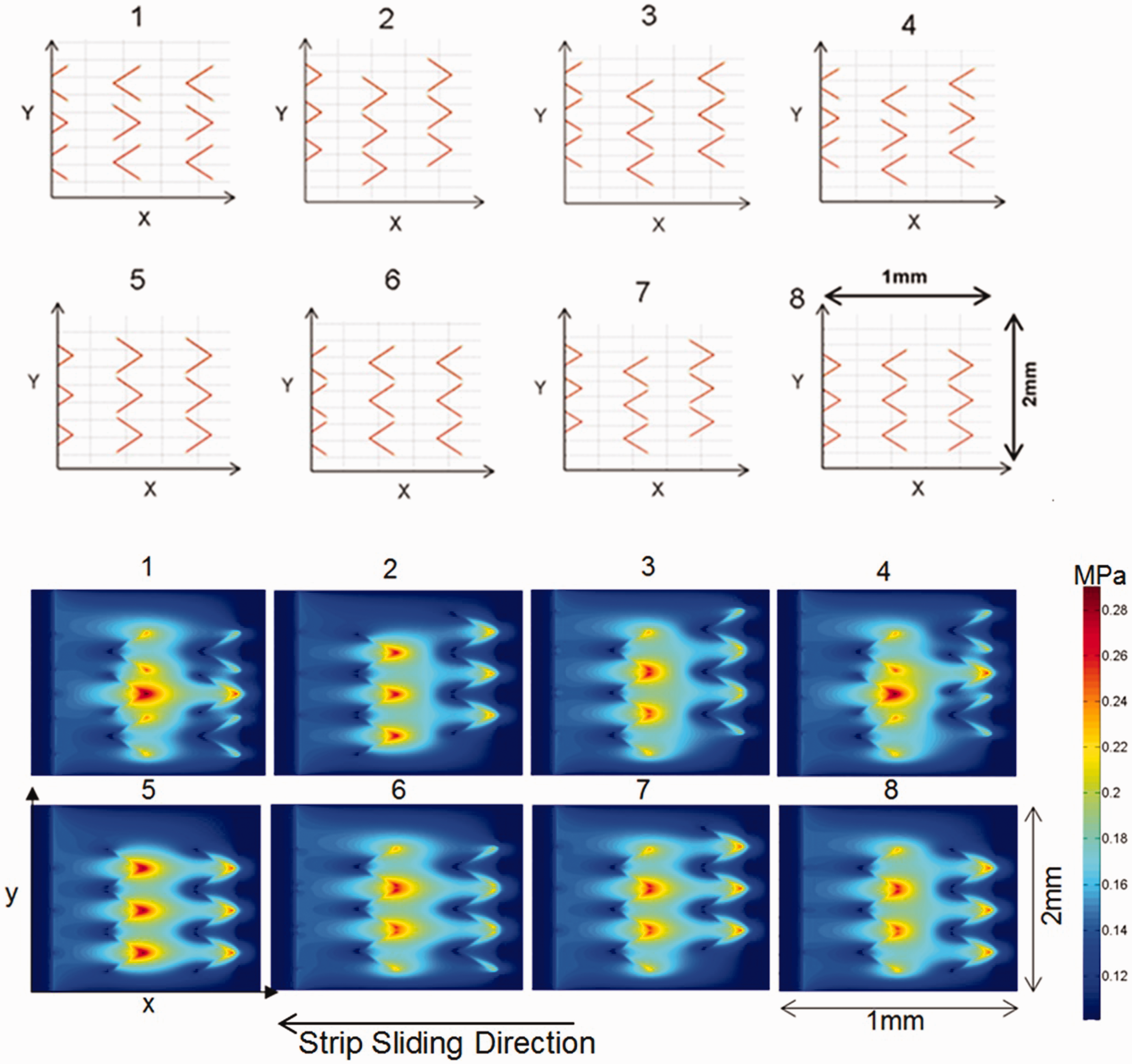
Experimental results
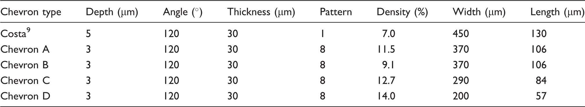
With the results of the aforementioned parametric analysis, it was decided to create four types of chevron textures. The chevron parameters chosen for this purpose are: a chevron thickness of 30 µm (as the variation on the generated friction was caused by increasing density rather than any other effect, see section ‘Numerical parametric studies’). Furthermore, by keeping the laser beam width for a chevron leg thickness of 30 µm the production time of the samples was significantly reduced. A chevron depth of 3 µm was chosen to adhere to the aforementioned height-to-width ratio of 0.1, noted to be an optimum ratio by Etsion and Sher. 28
Although the results of parametric study for the chevron inclusion angle indicated an optimum values of 80° (representing a 50° equivalent cross-hatch angle), it was decided to opt for an inclusion angle of 120°. The main reason for this was that the ultimate motivation for this research is to use the eventual configuration from the current study for use in advanced cylinder liner technology of high performing engines. Additionally, it has been noted in practice that features with shallower cross-hatch angle perform better in engine applications which, as noted above, has been confirmed by the numerical predictions in Spencer et al.
55
Different distributions of chevrons are used (Table 5, Figure 12).
Distribution of chevrons left to right, top row: Patterns A and B, bottom row: Patterns C and D. Predicted reduction in friction with the patterns made for testing. Chevron parameters.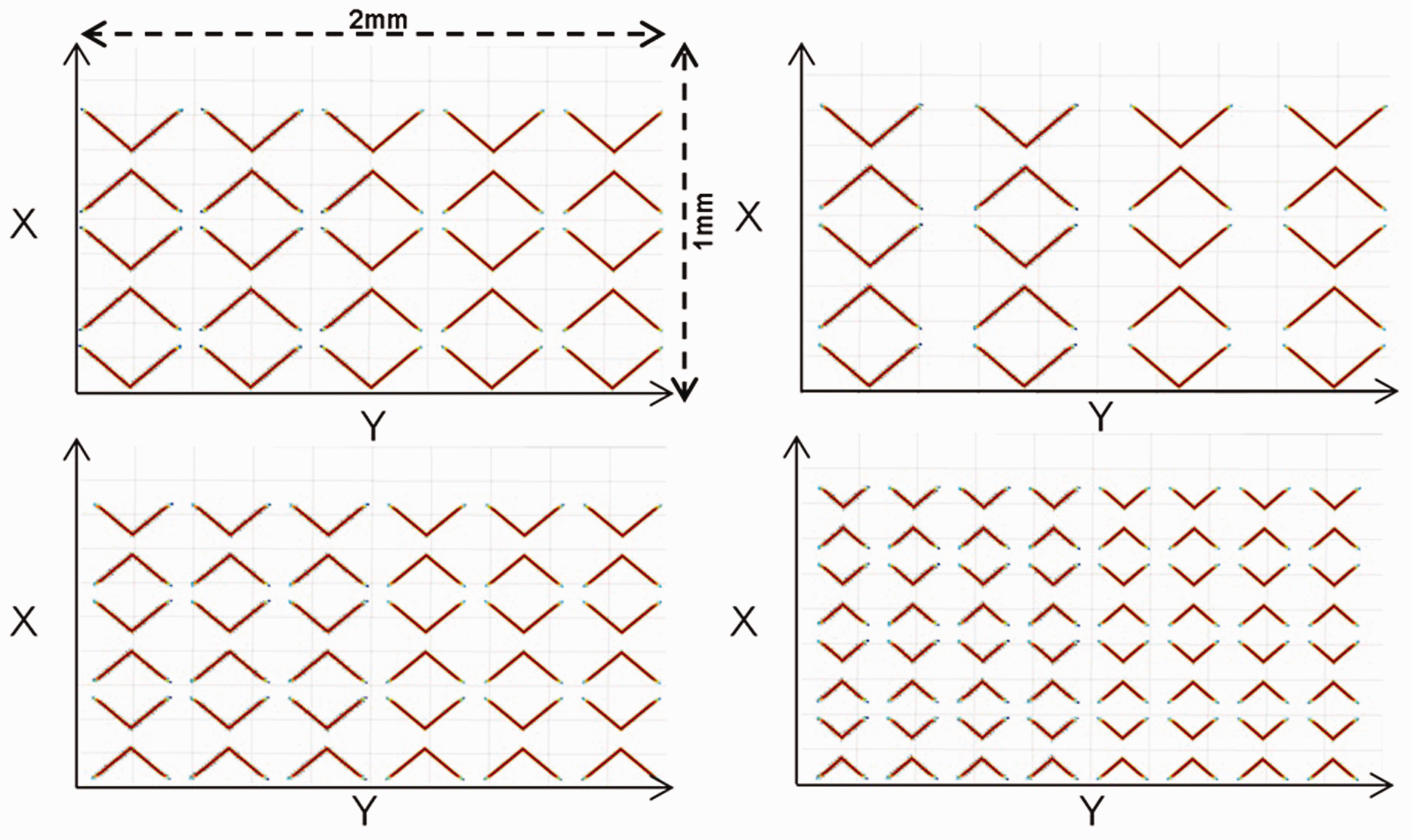
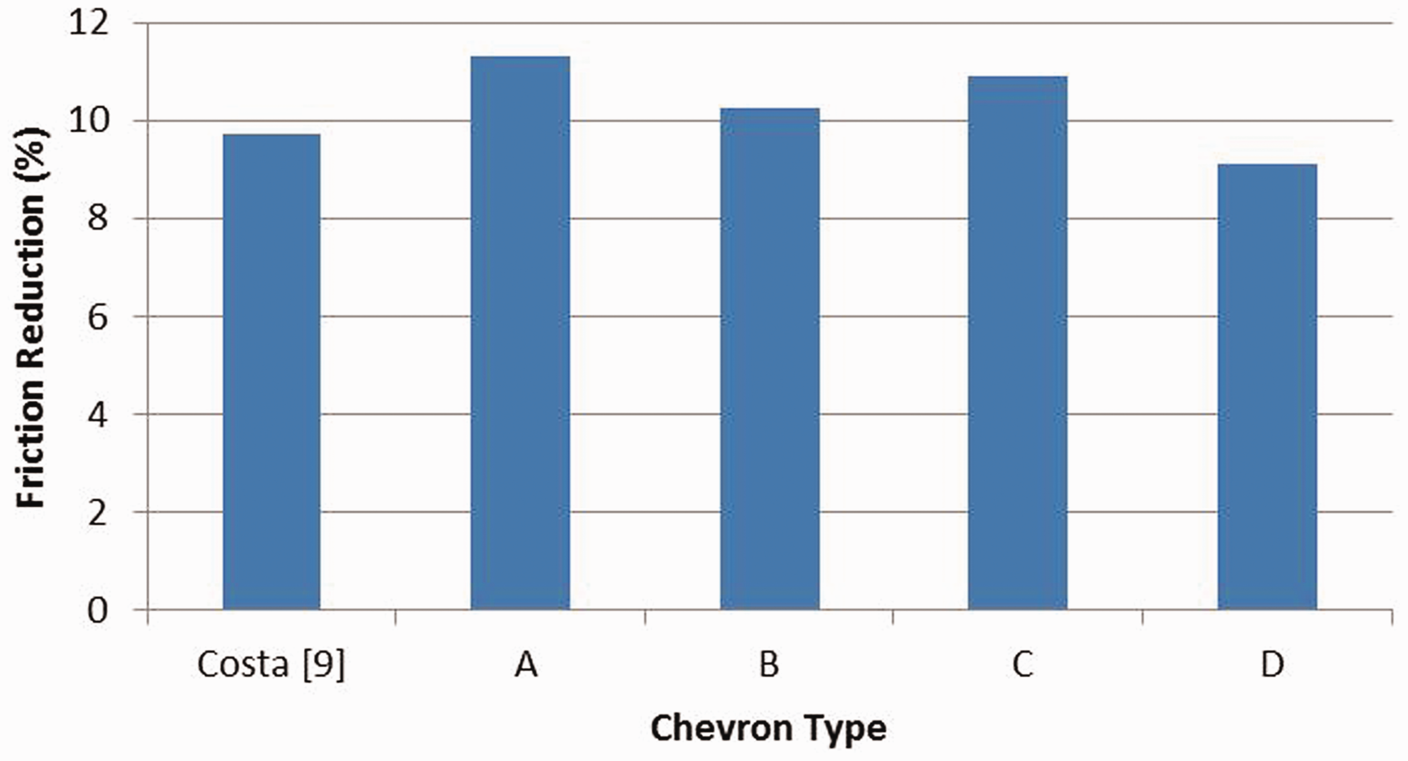
Numerical simulation of these various patterns yields the percentage reductions in friction with respect to an un-textured nominally smooth surface.
The new chevron patterns show reduction in friction of around 4% with respect to the original pattern based on that of Costa and Hutchings. 9
All the new patterns and that in Costa and Hutchings 9 were manufactured and subjected to testing (see Appendix 2 for the test protocol) using the precision slider rig, described in section ‘Reciprocating sliding contacts’.
The initial step was to validate the numerical analysis, thus gain confidence in the result of parametric analysis. This comparison is shown in Figure 14(a). The region containing the chevron textures is highlighted in the figure. A reduction in predicted as well as measured friction is noted as the sliding strip enters the textured region. A sharper drop in friction is noted in the case of measured results at the onset of textured region. This indicates that in practice a lesser Poiseuille shear exists at contact inlet. This means that there must be a greater volume of lubricant in the inlet region of the contact than the just flooded condition assumed in the numerical analysis. Nevertheless, an overall good agreement is noted between the numerical prediction and that measured.
Prototype testing of the various manufactured laser etched chevron patterns in Figure 12: (a) Validation of numerical predictions; (b) Bench marking of various patterns.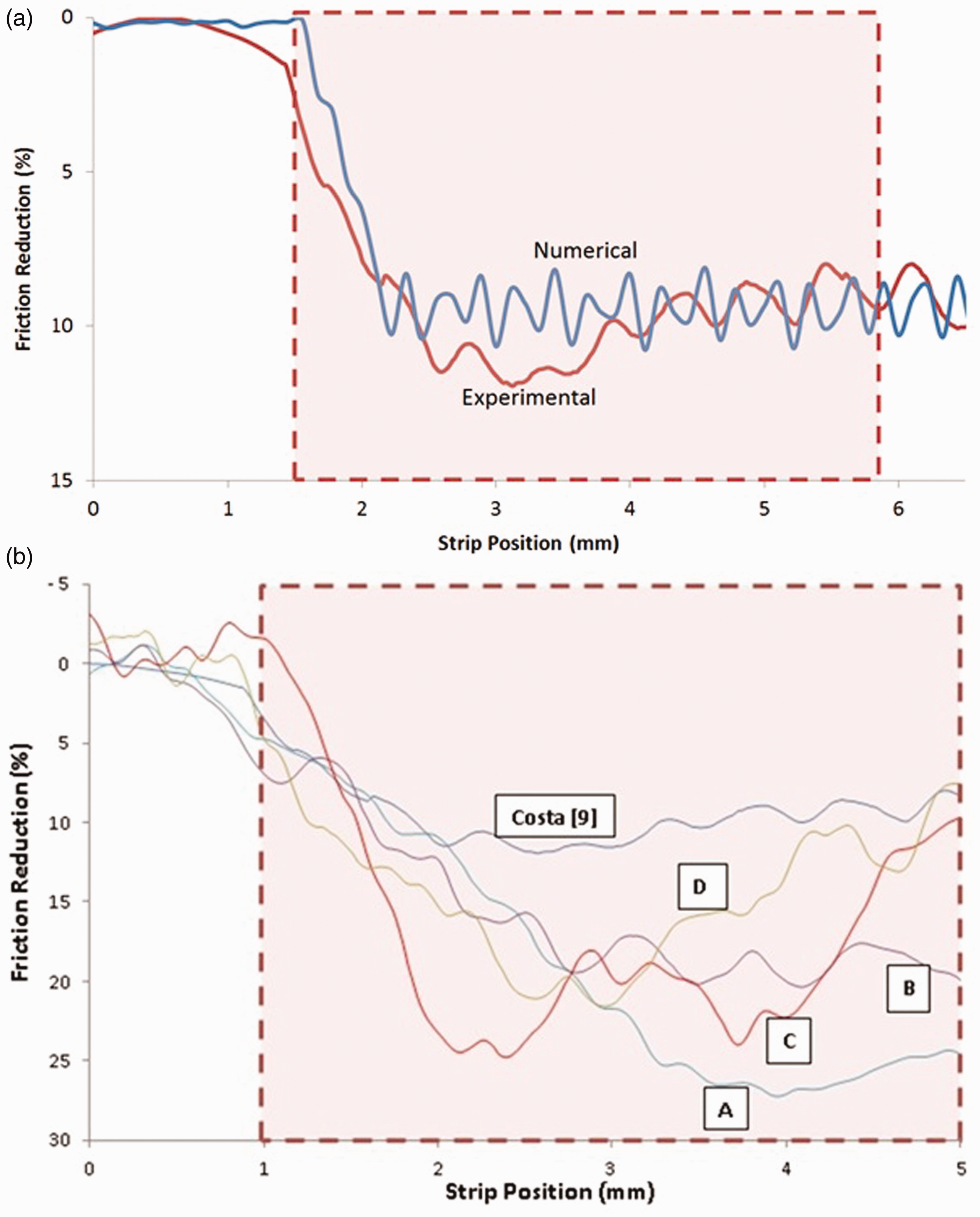
The next step was to measure friction for the various patterns in Table 5. The results are shown in terms of friction reduction with respect to an un-textured surface in Figure 14(b). All textured patterns show significant reduction in friction relative to an untreated surface. There is a difference in an initial drop in friction between different textured patterns at the onset of entry into the textured region. As already noted, this is mainly due to Poiseuille shear on the account of encountered inlet pressure gradient in the presence of identical measured sliding speed (thus almost the same nominal Couette shear) and load (see also ‘Concluding remarks’).
Concluding remarks
It is shown through numerical analysis and precision measurement that for low sliding motion textured surfaces of suitable geometry, pattern and distribution can induce micro-hydrodynamic pressure perturbations, thus enhance lubricant film thickness. This leads to a reduction in generated conjunctional friction. It is also shown that various texture geometrical attributes and distribution can be used to ‘optimise’ the prevailing regime of lubrication, thus reducing friction. It is clear that a choice of these pertinent parameters depends on the application in mind and the operating conditions such as sliding speed and conjunctional load. Therefore, ‘optimisation’ would be application dependent.
In particular, the study shows that lubricant retention in the created micro-reservoirs as well as pressure perturbations at the inlet conjunction can result in differing extent of effective micro-wedge effect, which is also crucially dependent on the supply of the lubricant at the contact inlet. In practice, such as in light-to-medium loaded reversal region of piston–cylinder liner contact in transition from compression to power stroke, supply of inlet meniscus to the contact cannot be controlled on the account of high surface temperatures in the combustion chamber. There is also modal deformation of contiguous surfaces, such as the piston compression ring and the cylinder liner 45 which deviate from their ideal circumferential conformity. Therefore, unlike mechanical seals and rings where entrance wedge geometry can be controlled to a certain extent as well as a fully flooded inlet, optimisation to the degree of minutiae in cylinder technology would be cost inefficient so long as any significant reduction can be achieved in line with the cost of manufacture. The study shows that texturing has the potential to meet the practical requirements, but as shown by Howell-Smith et al. 30 not to the extent indicated under controlled and relatively ideal laboratory conditions.
Footnotes
Acknowledgements
The authors thank the EPSRC and all the partner organisations in the Encyclopaedic project, in particular in this instance to Capricorn Automotive.
Conflict of interest
None declared.