
Abstract
Background and objective:
The Shape-Memory Alloy (SMA) or smart alloy stent can be used in the upper respiratory system by reducing problems such as changing the shape according to the actual conditions of the body compared to other stents.
Methods:
In this study, the behavior of 2 types of SMA stents with different metallurgical properties was studied using the Finite Element Method (FEM). Tracheal geometry was obtained from CT images of a healthy man. Then, a computational model of a real human trachea was selected to analyze the deformation of the trachea after implantation of the prosthesis. Finally, it was analyzed under the maximum average static pressure of the entrance to the trachea using the Fluid-Structure Interaction (FSI) approach. A mesh based on unstructured elements for air and structured elements for the tracheal wall was created to perform simulations using ANSYS software.
Results:
The deformation of the stent was compared and analyzed with the deformation of the healthy trachea in the absence of the stent. The results presented that the most deformation in the trachea before stenting is up to 8.3 mm. The behavior of SMA2 with a deformation of 5.8 mm was more consistent with the deformation conditions of the trachea for real body conditions without the presence of a stent.
Conclusions:
As much as the deformation is reduced by the degree of stress concentration at the connection point of the stent to the trachea, the risks of stent displacement and patient suffocation are avoided.
Introduction
Stents with SMA are usually tubes inserted into part of the upper respiratory system to allow airflow and keep the airway open after the tumor is removed. The superelastic properties of SMA, which can be closer to the viscoelastic behavior of tissue, reduce the risk of stent damage to the body. Therefore, respiratory problems, including stent displacement and, as a result, airway obstruction, can be significantly reduced. The trachea is a very deformable tube that changes volume during sneezing, coughing, and normal breathing. It is composed of a muscular membrane and cartilaginous rings that go posteriorly and longitudinally toward the trachea region. The major task of the cartilaginous frames of the trachea is to keep the trachea open despite intrathoracic pressure through respiratory reflexes. 1 Wall pressure and smooth muscle contraction create tensile and bending stresses in the cartilage to regulate airflow and adjust airway diameter. Therefore, how prosthesis implantation affects tracheal response and a clear comprehension of how this process works are challenging and essential. Only some investigations have been performed on the manner of the stent and trachea in various breathing states. This is particularly important for patients who have to undergo surgery. Understanding the processes of breathing, coughing, and sneezing in the healthy trachea after stent implantation is vital to designing more compatible prostheses. Tracheal and laryngeal stents are hollow or solid absorbable or non-absorbable ducts of different materials, sizes, and shapes whose function is to open the passage of the trachea. Although patients regain about half of their primary breathing ability after implanting the prosthesis, other challenges, such as coughing problems, may occur because the stents enhance the stiffness of the airway wall. 2 Silicone prosthesis increases the risk of mucosal occlusion. Those have thine internal diameter because of their thick wall. 3 For this reason, a good comprehension of pathological tracheal flow and health and distinctive characteristics of stents with tracheobronchial SMA through FSI analysis is important to modify clinical results.
Most of the previous numerical studies investigated the airflow design using ideal or approximate airway geometries. 4 A large region of the respiratory system with a thin blood surface is exposed to aerosols in the inspiration air. If inspiration pollutant particles are toxic, the interaction of aerosols and the respiratory system may cause serious risks and damage to human health. 5 Numerical simulation can provide critical quantitative flow information using geometric samples extracted from computed tomography (CT) images. A C-shaped trachea may enable more air inflow into the left bronchus and reduce right lung breathing. 6 Significant differences appear in the respiratory system during human growth. Understanding respiratory airflow in different age groups is important in treating respiratory disorders at certain ages. 7 A few are considered precise airway geometry obtained from Magnetic Resonance Imaging (MRI) and CT. 8 The characteristics of inhaled flow in a lung airway have been numerically studied. 9 The airflow velocity ratios through the inner branches are the same as their main branches. 10 The lower bronchi have 2 trunks, with the axial velocity being more robust. With the enhancement of the Reynolds number, the airflow in the hub, lower, and left central bronchus increases; that is, the flow changes to the left and down.11,12 The velocity map was developed using in-silico modeling. 13 By considering the slow incompressible three-dimensional flow in the branches, which represents the 3 to 6 generations of the human respiratory system, the airflow fields, and microparticles transfer under natural breathing conditions. Not all of these studies consider airway deformation.14,15 The deposition efficiency of aerosol particles in bifurcated airways during the exhalation phase has been investigated using single-branch tube models with different branch angles for symmetric and asymmetric branch geometries. 16 The deposition pattern in the model can be determined experimentally in different parts of the model. 17 The outcomes demonstrate that the inlet velocity profile greatly affects the airflow patterns, pressure drop, and mass distribution in the symmetrical model. There may need to be more than 3 generation airways to study bifurcation flow in pulmonary disease airways, and an airway model of 4 or more generations is necessary to obtain better predictive results. 18 So far, various studies have been done regarding the FSI to consider tracheal deformation. 19 The results indicate sensitivity to geometrical features. In addition, the results of strain levels obtained from tissue analysis are significant because these strains can induce inflammatory responses at the cellular level, thereby damaging airway tissues. 20 Until now, the implantation of a respiratory prosthesis has been modeled. Boundary conditions for respiratory reflexes are applied at the inlet and outlet surfaces. 21 Also, the FSI investigation of a human trachea has been studied to consider wall stresses, airflow patterns, and deformations under pathological and physiological states. 22 Deformation of airway walls is considered to analyze airway wall stresses and airflow patterns in first-generation lower airways in a realistic lung geometry.23 -25 There is an enhancement in the stiffness of the tracheal wall at lower temperatures. 26 In most of these researches, separated tracheal cartilage is treated as a linear elastic material. Regarding the smooth muscle of the human trachea, many previous studies have dealt with its stiffness, flexibility, and elasticity and the effect of temperature on biomechanical index relationships. 27 Nowadays, the performance of smart stents is of interest due to new medical applications. Considering the lack of conducting and presenting documented numerical research related to the role of metallurgical and mechanical properties of materials in the performance of stents, the purpose of this investigation is to use the FEM to study the biomechanical behavior of a new type of stent designed from SMA. This novel stent with different biomechanical properties will be used considering real severe respiratory conditions, including sneezing, for use in the tracheal region under loading with FSI boundary conditions.
Materials and Methods
Properties of SMA
Auricchio’s macroscopic model to explain the superelastic behavior of SMA is based on Helmholtz’s thermodynamic free energy. Where the strain consists of 2 parts: the change of state and the other is linear elastic. In the current study, the properties of SMA for stents were defined as a subprogram based on Auricchio’s theory according to Tables 1 and 2.
28
In these tables,
List of parameters related to the properties of SMA1 material.

List of parameters related to the properties of SMA2 material.

The Geometry of the Studied Upper Respiratory System
In this section, the modeling review and its characteristics are mentioned first, and then the grid study and validation results obtained are analyzed. The geometry used in this research is a collection of digital medical images in DICOM format, and it is related to a 31-year-old human, which was taken at the MRI Radiography Center and transferred to Mimics software. The first step of making a model is to retouch it. Then, the optimal value of the lower and upper threshold limits of the images must be selected. According to the investigated geometry, which includes the nasal inlet to the end of the trachea, the air interval is given to the software. All air areas in the body can be identified by adjusting this interval. Figure 1 presents the CT images of the upper respiratory system in the Mimics software domain. The green zone indicates the airway in the respiratory system.

3D image processed by Mimics software.
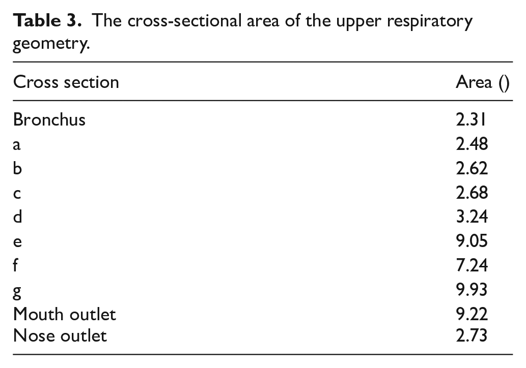
Figure 2 presents an example of the partitioned upper respiratory system according to the previous study. 29 The subject provided informed electrical consent to have data from his medical record used in this research based on previous research. The study was approved by Teb Karan Aran Far Company Human Research Ethics Committee in Iran (Ref No: RS141220). The incompatibility of the properties of the stent wall with the real conditions of the human body leads to patient dissatisfaction. These maximum average static pressures are based on the highest respiratory rates in the sneeze reflex. When investigating critical states, it is customary to consider the most severe respiratory peak states. 29 In some cases, displacement of the stent occurs after severe respiratory reflexes such as sneezing and, as a result, suffocation of the patient. The main goal of this research is to replace the properties of the stent with the properties of the SMA material. Table 3 presents the cross-sectional surface of the geometry presented in Figure 2.

Characteristics of the upper airway: (A) geometry and (B) anatomical segmentation.
The cross-sectional area of the upper respiratory geometry.
Governing Equations and Grid Generation
In the current study, the air was assumed to be incompressible and viscous. 29 Mass conservation (equation (1)) and momentum (equation (2)) equations are the governing equations in the human respiratory system for turbulent airflow. These equations are:


Where,
Where in this equation,

In this real model, the maximum average static pressure entering the larynx is 7 kPa (section b in Figure 2A), and it exits the larynx at 7.8 kPa (section c in Figure 2A). In patients who develop cancer in the larynx area (bc zone in Figure 2A), the surgeon inevitably removes the cancerous larynx from the body and replaces it with a stent. The airway walls were considered smart walls based on Tables 1 and 2. In the present model, the fixed boundary conditions for the mouth and end of the trachea are where the flow rate exits and enters, respectively. In the numerical model, the flow rate entrance is from the end of the trachea, and the FSI boundary condition is applied to the smart walls in contact with the airflow. Figure 3 demonstrates the mesh characteristics of the stent shell and the airflow domain. It has been tried to use structured elements in this geometry as much as possible. The boundary layers are meshed with hexahedra elements. The grid independence diagram is presented in Figure 4. The number of grids after checking the grid-independent is approximately 843 k elements. This diagram is based on the pressure parameter (P) and wall shear stress (WSS). Pressure and WSS parameters remain constant within the acceptable range of 843 k to 982 k elements. Figure 5 presents the model validation diagram. The trend of velocity profile variations in the trachea of the current study is very similar to the experimental study of Ball et al. 30 The reason for their complete non-compliance can be attributed to the difference in geometries.

Grid generation: (A) 2.5 mm thickness shell of the stent and (B) mesh of the airflow inside the shell.

Grid independence diagram based on pressure and WSS indexes.
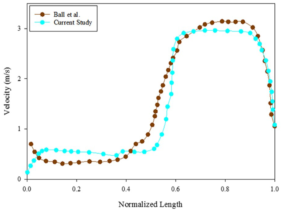
Validation diagram with a laboratory study using the hot-wire method of Ball et al. 30
As mentioned, the mechanical properties of the shell have been introduced to ANSYS software based on Tables 1 and 2. ANSYS allows the user to define geometry properties differently from the software default. In this study, ANSYS 2023 R1 was used due to its optimal computing power in the field of medical applications such as stent analysis. Figure 6 presents the contour of WSS alteration. The highest value of this parameter occurs in the inlet collar connecting the stent with the larynx, and its value is approximately 10.5 Pa. The WSS is one of the most important index outputs from CFD. It is very difficult to calculate the WSS in vivo. The WSS changes in the current study are very close to Koombua and Pidaparti 19 study, which can be another proof of the correctness of the present simulation.

The contour of WSS variation.
Result and Discussion
SMA or memory alloy stents with unique features will have favorable biomechanical and clinical applications. Entire mechanical hysteresis loop, good radial mechanical strength, maximum radial resistive mechanical strength, high state strain, less stress in the critical points of the stent, high strain, or, in other words, the length of the superelastic deformation zone, maximum displacement, the formation of a high percentage of martensite in the structure of the stent, the absence of the stent in the elastic range and also in the safe range of the stent against failure are among the features of smart alloy stents.
Figure 7 presents the Von Mises stress applied to the stent shell. The highest tension is created at the connection between the stent and the trachea, and its value varies from approximately 74.8 kPa for SMA1 to 83.1 kPa for SMA 2. Therefore, it is very important to pay attention to the surgical method of placing the stent in the patient’s body due to the concentration of stress created at the connection face of the stent. On the other hand, when the stent is exposed to long-term cyclic loads caused by breathing, it may undergo fatigue deformation at the connection face of the stent.

Von Mises stress obtained for: (A) SMA 1 and (B) SMA 2.
Figure 8 presents the deformation contour of the stent shell. The most considerable deformation value varies up to approximately 15.8 mm for SMA1 and 5.8 mm for SMA2 in the middle of the stent. If this deformation is the same as the deformation of the trachea in real conditions, it can be expected that the performance of the stent will be optimal. Therefore, the amount of stress concentration at the connection point of the stent to the trachea will be reduced, and the risks of stent movement and suffocation of patients will be avoided.

Deformation contour obtained for: (A) SMA 1 and (B) SMA 2.
Figure 9A presents the deformation diagram obtained to investigate the deformation of SMA 1 and SMA 2 along the length of the stent. As mentioned, the most significant deformation is in the middle of the stent. Figure 9B presents the deformation contour in the trachea for real body conditions without the presence of a stent. This figure indicates that the maximum deformation created in the trachea before stenting is up to 8.3 mm, based on the previous study. 29 Therefore, the behavior of SMA 2 with a deformation of 5.8 mm is more consistent with the deformation conditions of the trachea for the real conditions of the body without the presence of a stent. Then, the stent can be expected to have a more suitable and favorable function with the body. The hybrid configuration contour of velocity, pressure, turbulence, WSS, deformation, stress, and strain can be seen in Figure 10 for the stent with SMA 2 material. In this figure, the brown portion displays the location of the stent, leading to a better understanding of stent performance. This hybrid contour of the stent with the real model can exhibit the behavior of the stent in vitro in the human upper airway. According to this figure, the highest pressure occurs in the larynx and trachea, with a value of 8.9 kPa. The highest instantaneous speed occurs in the pharynx, with a value of 129 m/s. The greatest deformation in the downstream region of the prosthesis is obtained with an amount of 5.8 mm. The highest amount of stress and strain occurs in the larynx, with values of 83 kPa and 0.23, respectively.

Deformation diagram obtained for: (A) SMA1 and SMA2 during stent length and (B) deformation contour in the trachea for real body conditions without the presence of a stent. 29

Contours of pressure, velocity, WSS, deformation, stress, and strain for SMA2: (A) pressure, (B) pressure with cross-section, (C) streamline, (D) velocity vector, (E) WSS, (F) turbulence intensity, (G) stress, (H) strain, and (I) deformation.
Accurate knowledge of stent deformation is necessary to analyze the adverse and dangerous effects of stent displacement and suffocation in the upper respiratory system. The most muscular respiratory reflexes of the body occur during coughing and sneezing. In this study, airflow indexes, such as pressure and velocity, were obtained in the stent for larynx implementation in the upper airway. After that, the indexes of the wall, including stress and deformation, were calculated. Medicine is the first field in which memory alloys found many applications. The reason for this is the suitability of body temperature for the performance of smart alloys. Research on the respiratory system has always been of interest to researchers from various attitudes.31,32 The scope of the current study investigates the behavior of the 2 smart stents in the most severe respiratory sneeze reflex. It would be crucial to analyze the stent’s behavior under different respiratory conditions (normal breathing, coughing, physical exertion), compare it with other materials, and investigate material fatigue and degradation, which are critical aspects for the long-term success of the prosthesis suggested continuing investigating the behavior of smart stents. The present study includes strengths such as smart stent investigating in real body geometry conditions, which have yet to be studied numerically in the human trachea. The highest pressure appears in the trachea during the sneeze reflex. Therefore, it is important to examine this zone from a special position.
Conclusion
It is very difficult to simulate the behavior of smart stents for reasons such as the completely nonlinear behavior of the material, the intricate geometry of the respiratory system and the large deformation. The model presented in this study has the ability to predict the biomechanical behaviors of smart stents for use in the upper respiratory system based on the 3D FEM model using ANSYS software. The highest tension is created at the connection between the stent and the trachea. It is better if the SMA deformation is closer to the tracheal deformation. This will reduce the stress concentration at the stent-tracheal junction. In addition to making the patient feel more comfortable, the risks of stent displacement will be reduced. The normal tracheal deformation is 8.3 mm (Figure 9B). Therefore, SMA 2, with a deformation of 5.8 mm, is more compatible with the behavior of tracheal deformation than SMA 1, with a deformation of 15.8 mm. This research can provide a suitable way to determine the biomechanical behavior of stents used in the upper respiratory system, considering the effects of those metallurgical and biomechanical properties.