
Abstract
The spinal diseases commonly faced by people in the 19th century included intervertebral disc degeneration, tuberculosis and congenital defects that resulted in neurological impairment and global disability. To address these issues, cervical spine surgery was performed. Modern techniques currently used in spine surgery include interbody devices, pedicle screws, artificial discs and bone grafts. The postoperative complications clinically reported during follow-up include nonunion and implant subsidence, which remain significant drawbacks. The objective of this study is to develop a 3-dimensional finite element model of the C2-C7 cervical spine and validate it against existing experimental studies. The loading conditions considered for this study include a compressive preload of 50 N and a 1 Nm moment applied to the C2 vertebra, with the C7 vertebra fixed at the bottom. In this study, the biomechanical alterations of 4 different cage morphologies were analysed using finite element analysis. Valeo cages with 4 distinct designs were implanted at the C5-C6 level, and physiological motion at the surgical site was studied. Cage subsidence and migration, which can lead to adjacent segment disc degeneration, were also examined. Subsidence was primarily attributed to higher stress encountered in the cage, so stress distribution within the cages was evaluated. Additionally, stress distribution in the anterior plate and screws was analysed. The study concludes that introducing anterior plate and screw fixation helps prevent cage subsidence. Physiological motion at the surgical level was reduced compared to the intact model. Adjacent disc stress was also evaluated and found to be lower than in the intact model.
Introduction
Cervical spine problems include disc degeneration, disc herniation, spondylotic myelopathy and ossification of the ligaments.1 -3 ACDF (Anterior Cervical Discectomy and Fusion) surgery is performed to address these cervical issues. 4 The intervertebral fusion cage and anterior fixation are primarily used in ACDF surgery to maintain stability and restore intervertebral disc height on both the anterior and posterior sides.5,6 The post-surgical effects of ACDF surgery, such as subsidence, construct failure, misalignment, nonunion or pseudoarthrosis, are attributed to load sharing and stress transfer through the cage and anterior fixation plate.7,8 ACDF surgery is reported to be the most effective surgical approach for cervical spondylotic myelopathy, particularly in cases with severe intervertebral disc degeneration. Its efficiency is better in terms of cervical spine reconstruction and stabilisation, as well as decompression of the spinal cord caused by disc degeneration. Overall complication rates range from 13.2% to 19.3%. The occurrence of pseudarthrosis in ACDF surgery varies based on the levels of fusion. For single-level fusion, pseudarthrosis rates range from 0% to 4.3%. Readmission rates following ACDF surgery are 5.1% after 1 month and 7.7% after 3 months. 9 The prominence of anterior cervical plates can affect the surrounding tissues, causing postoperative dysphagia and oesophageal injury. 10 Anterior cervical discectomy and fusion is regarded as the best and most effective treatment for cervical myelopathy and radiculopathy.11,12 Multilevel surgeries present more challenges compared to single-level procedures . 13 In the fusion segment, after fixing the cage, there may be a possibility of abnormal range of motion in the adjacent segments. The abnormal and increased motion in the adjacent level to the fusion segment propagates adjacent segment disc degeneration.14,15 In ACDF surgery, the commonly used materials are titanium, PEEK, or a combination of both, which may provide better properties. 16 The cages currently available come in various shapes and sizes. The shapes of the cages include trapezoidal, rectangular and wedge-shaped designs.17 -19 The morphology of the cage plays a crucial role in the fusion process. Bone growth determines the success rate of fusion. Researchers have conducted studies on cervical cages that may be used for ACDF surgery.
Silicon nitride is an effective bio-ceramic material. Its toughness and strength make it a desired biomaterial for the implant. 20 The silicon nitride is found as a best biomaterial because it provides good toughness and the strength as an implant. The major advantage of Si₃N₄ is that it provides better osteoconductivity,21 -23 bacteriostasis and lack of subsidence of the cage in the cervical spine. 24 It improves radiolucency, wear resistance, 25 and supports the spinal fusion of the cage with the vertebra. This bioceramic material enhances the structural stability and bioactivity of the implant.26,27 The metallic biomaterials used in implant design include cobalt-chromium alloys and titanium, while the biopolymers include UHMWPE and PEEK. Silicon nitride exhibits higher compressive strength compared to other biomaterials.28,29 Its fracture toughness is greater than that of oxide bioceramics. 30 Additionally, silicon nitride has a low coefficient of friction and superior wear resistance. 31 Compared to metal implants, it provides better imaging properties with MRI or CT techniques. 32
When compared to titanium and PEEK as implant materials, silicon nitride promotes an environment conducive to bone tissue healing. However, its major disadvantages include low energy dissipation and higher manufacturing costs. 20 Currently, silicon nitride is used in implant devices for the cervical and lumbar spine.
Finite element analysis is an effective tool that provides valuable insights in biomechanical studies. It allows the investigation of scenarios impractical for human clinical studies. For example, it can evaluate intradiscal stress in the implant after cage placement and the range of motion in individual functional spine units.
In existing interbody fusion cages, common issues include subsidence of the fusion cages into adjacent vertebrae, adjacent segment intervertebral disc degeneration, and migration of the fusion cage.
This study aims to evaluate the biomechanical alterations following the placement of 4 different interbody fusion cages in the cervical spine at the C5-C6 level. The primary objectives are to:
1. Establish a finite element model of the cervical spine from the C2-C7 levels and simulate the model with different cage geometries at the C5-C6 level.
2. Compare the stress distribution in the cages and the anterior plate with screws for all physiological motions.
3. Analyse the adjacent disc stress for each cage.
4. Measure the subsidence of the cage for all geometries.
Materials and Methods
Intact FE model
An intact model of the cervical spine from C2 to C7 was generated using image processing software, based on a subject considered to be a 35-year-old male. The images were imported into Mimics 10.01 (Materialise Inc., Leuven, Belgium) for the reconstruction of the vertebrae. The thresholding option was used to differentiate the soft tissues from bone. After region-growing, the irregular surfaces were modified without compromising the geometry.
The geometry of the vertebrae was then exported to reverse engineering software, Geomagic Design X 16.0 (Geomagic Inc., North Carolina, USA), for smoothing operations. The irregular solid model was converted into a surface model using Geomagic’s smoothing functions. The meshing of the vertebrae, intervertebral discs and ligaments was performed using HyperMesh-21® software (HyperMesh, Altair Engineering®, USA). Element types and material properties were assigned as part of the preprocessing for the finite element model. The meshing of the surface model was completed in HyperMesh.
The anterior and posterior sides of the vertebrae were separated. The intervertebral disc was divided into the annulus fibrosus and nucleus pulposus, and the disc was covered with vertebral endplates on both the anterior and posterior sides.
The implant was designed using SolidWorks. Anterior plates and screws were modelled, with 4 screws inserted into the C5 and C6 vertebrae. At the surgical level (C5-C6), a cage was inserted. The surface and finite element model are shown in Figure 1.

Surface model Intact cervical spine C2-C7 and cage implant model, (A) frontal view of the intact cervical spine, (B) lateral view of the intact cervical spine, (C) frontal view of C2-C7 with implant at C5-C6 level and (D) lateral view of C2-C7 with implant at C5-C6.
Design of cage with anterior fixation for C5-C6 level and finite element modelling
At the C5-C6 level, the first cage model, Valeo II C, has a length of 14 mm, a width of 12 mm and a convex height of 6 mm. It is named Valeo M-1 and was inserted into the surface model. The second cage model considered, also Valeo II C, has a length of 14 mm, a width of 12 mm and a height of 8 mm. It is named Valeo M-2.
The third cage model, Valeo II C, has a length of 16 mm, a width of 14 mm and a convex height of 6 mm. It is named Valeo M-3. The fourth cage model, Valeo II C, has a length of 16 mm, a width of 14 mm and a height of 8 mm. It is named Valeo M-4.
For all 4 models, an anterior plate and screws were inserted. The individual dimensions are provided in Table 1. The anterior and posterior heights of the plate are also mentioned in Table 1, as shown in Figure 2. The geometry of the plates and screw with dimensions were provided as Supplemental Materials.
Dimensions of the Valeo cage with dimensions.


Meshed model: (A) frontal view of C2-C7 with implant at C5- C6 level, (B) lateral view of C2-C7 with implant at C5-C6, (C) Valeo M-1 cage at C5-C6 level, (D) Valeo M-2 cage at C5-C6 level, (E) Valeo M-3 cage at C5-C6 level and (F) Valeo M-4 cage at C5-C6 level.
The cervical spine finite element model in this study includes the C2 to C7 vertebral bodies, posterior structures, intervertebral discs, vertebral endplates and 5 major ligaments. The cage was inserted at the C5-C6 level. The vertebrae, intervertebral discs, and cage were modelled using first-order solid tetrahedral elements. The interaction between the cage and vertebra was defined as frictional surface-to-surface contact with a coefficient of friction of 0.3.33,34 The geometrical model of the intervertebral disc was modelled using Pooni et al. 35 The annulus and the nucleus were modelled as separate entities and the material properties assigned were shown in the Table 2. The interaction between the bone graft and the cage was defined as surface-to-surface contact with a coefficient of friction of 0.07. 36 The ligaments used in this study include the anterior longitudinal ligament (ALL), capsular ligament (CL), posterior longitudinal ligament (PLL), ligamentum flavum (LF) and interspinous ligament (ISL). The geometry of the ligaments was constructed based on values from the literature, 37 and they were modelled using tension-only link elements.
Material properties and element details of components of the developed FE model.

In the surgical simulation, the anterior longitudinal ligament and the intervertebral disc were completely removed at the C5-C6 level. The components were divided to assign material properties, as shown in Table 2. The cage material was assigned as silicon nitride, while the anterior fixation components were modelled using titanium plates and screws.38 -40
Following a convergence test, it was determined that a 0.5 mm element size was optimal. 41 The accuracy of the convergence test for the finite element model was found to be 3%. 41 The meshed model of the cages is shown in Figure 2.
Loading and boundary condition
The meshed model was imported into ANSYS 18.2 (ANSYS, Inc., USA). The 6 physiological motions in this study were simulated using 6 loading conditions of the cervical spine. The finite element model was validated against both experimental and finite element studies. 42
A compressive load of 50 N was applied to the C2 vertebra, along with a 1 Nm moment in the sagittal, axial and frontal planes to simulate flexion, extension, left lateral bending, right lateral bending, left axial rotation, and right axial rotation.43,44 The nodes on the inferior surface of the C7 vertebra were constrained.
Results
Range of motion
The intersegmental motion was analysed for all levels of the cervical spine following the placement of the cage at the C5-C6 level. At the C2-C3 level, the range of motion was studied and compared with the intact model. It was observed that with the Valeo M-1 and Valeo M-2 cages, the motion was reduced by 17.4% and 21.7%, respectively, during left axial rotation. For the Valeo M-3 cage, motion during right lateral bending was reduced by 16.1%, and for the Valeo M-4 cage, motion during right axial rotation decreased by 20.8%. At the C3-C4 level, the range of motion was also compared with the intact model. The Valeo M-1 and Valeo M-2 cages reduced motion by 16.7% and 22.2%, respectively, during left axial rotation. For the Valeo M-3 cage, motion during right lateral bending was reduced by 15.6%, while for the Valeo M-4 cage, motion during left axial rotation decreased by 16.7%.
At the C4-C5 level, motion during right axial rotation was reduced by a maximum of 27.8% across all models. At the C6-C7 level, for the Valeo M-1 cage, motion during flexion was reduced by 19.4%. For the Valeo M-2 cage, motion during left lateral bending was reduced by 17.4%. For the Valeo M-3 cage, motion during left axial rotation was reduced by 13.8%, and for the Valeo M-4 cage, motion during right axial rotation decreased by 15.6%. In summary, across all levels, motion was reduced for all physiological motions in comparison with the intact model. The physiological motion for the 4 cages was compared with the intact model, as shown in Figure 3.

Comparison of range of motion for Valeo M-1 cage, Valeo M-2 cage, Valeo M-3 cage and Valeo M-4 cage with the intact model.
Range of motion in the surgical level C5-C6
In the cage fixed level C5-C6 the motion was analysed in that the left lateral bending the motion was reduced by 56% for the Valeo M-1 cage. In the left axial rotation, the Valeo M-2 cage, the motion was reduced by 54.5%. In the Valeo M-3 cage in the right lateral bending the motion was reduced by 57.1%. In the Valeo M-4 cage in flexion motion was reduced by 60%. The surgical level range of motion is shown in Figure 4.

Surgical level range of motion compared with intact model.
Stress analysis for the Valeo cage
The stress analysis of the cage was analysed for the Valeo M-1 in the left lateral bending the stress is around 650.4 MPa and in the flexion the stress was 120.8 MPa and it is less when compared with the other physiological motion. For the Valeo M-2 in the left lateral bending the stress is around 830.4 MPa and in the flexion the stress was 95.5 MPa and it is less when compared with the other physiological motion. For the Valeo M-3 in the right lateral bending the stress is around 1853.9 MPa and in the flexion the stress was 293.2 MPa and it is less when compared with the other physiological motion. For the Valeo M-4 in the right lateral bending the stress is around 724.8 MPa and in the flexion the stress was 119.9 MPa and it is less when compared with the other physiological motion. The stress analysis in the cage is shown in the Figure 5. The average stress values of the cages were given in the Figure 6.
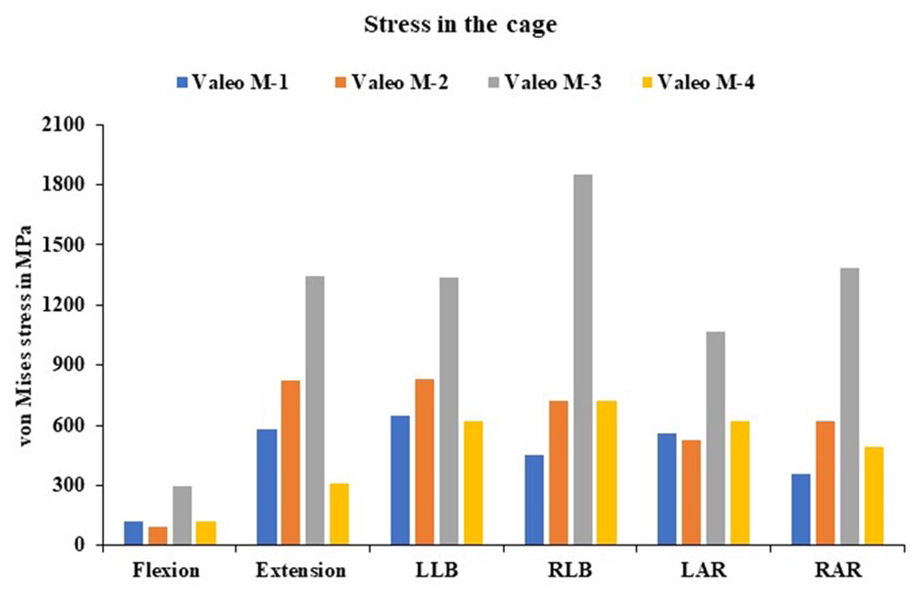
von Mises stress values in the cage for Valeo M-1 cage, Valeo M-2 cage, Valeo M-3 cage and Valeo M-4 cage.

von Mises stress in the Valeo cage.
Stress analysis in the anterior fixation
The stress analysis for the anterior fixation was analysed for all the cage models; the stress was varied from 577.1 for the Valeo M-2 model and 336.5 for the Valeo M-4 model in extension motion. The lesser stress values were seen for flexion in the Valeo M1, M3 and M4 and its stress is around 100.4, 85 and 70.87 MPa. In the left axial rotation for the Valeo-M2 the stress is 177.8 MPa. The stress analysis in the anterior fixation is shown in Figure 7. The average stress values of the anterior fixation with screws are given in Figure 8.
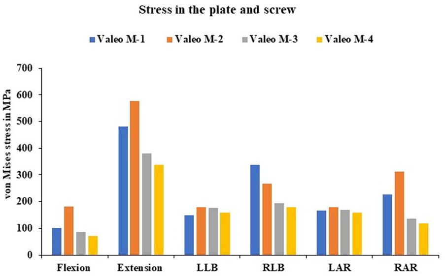
von Mises stress values in the plate and screw for Valeo M-1 cage, Valeo M-2 cage, Valeo M-3 cage and Valeo M-4 cage.

von Mises stress in the anterior plate and the screw.
Adjacent side disc stress analysis
The intervertebral disc stress in the superior adjacent disc C4-C5 level were studied in all the cages. We found similar results: the stress values were reduced varied from 79.7% to 71% during the flexion motion when compared with the intact model. In the inferior adjacent segments C5-C6 level, we observed the stress values are higher for all the cage and it varied from 49% to 154% during the left axial rotation; the values look higher when we compare with the intact model. The adjacent side intradiscal pressure is shown in Figure 9.

Intradiscal stress at adjacent segments C4-C5 and C6-C7 level.
Subsidence of the interbody cage
The subsidence was studied for all the physiological motion for the different geometry cages. The Valeo M-1 cage subsidence was 0.3 mm during extension which is a higher value and 0.1 mm during the axial rotation. The Valeo M-2 cage subsidence was 0.3 mm during flexion, right lateral bending and left axial rotation and 0.1 mm during left lateral bending. The Valeo M-3 cage subsidence was 0.4 mm during extension and 0.1 mm during flexion. The Valeo M-4 cage subsidence was 0.4 mm during extension and 0.1 mm during left lateral bending, right axial rotation. The subsidence of the cage is shown in Figure 10.

Subsidence in the cage at the C5-C6 level.
Discussion
The author Igarashi et al, studied the age at which the cage subsidence will occur in that they took 78 patients, the age was from 30 to 79 years, and in the results, they found there is no correlation between the age of the patient and the cage subsidence. 45 In a retrospective study, age groups of 18 to 70 were considered in that there is no significant correlation between the patient age and the subsidence of the cage. Hamada and Abou-Zeid.46,47 Nakanishi et al, 48 in this study, considered 42 patients and found there is no relation between the cage subsidence and the age of the patients. Bone mineral density between the end plate and the vertebral body plays a major role in the estimation of the intervertebral cage subsidence. Jin et al 49 and Lim et al 50 proposed that mechanical loads, when compared to the thickness of the vertebral endplate, cause failure. From this analysis we found the bone mineral density is inversely proportional to the interbody fusion cage subsidence.51,52 These finite element simulation findings demonstrate the influence of the material composition and the geometry of the cage for the cervical spine. A s-type dynamic cage was developed with titanium and PEEK material to find the best shape of the cage with bone graft because a higher stress in the cage will cause subsidence.53,54 In the ACDF surgery, after the cage is fixed between the vertebrae, a micromotion may exist between the vertebrae, and due to that the fusion rate may be failed so in order to control the motion and promote the fusion rate it is necessary to provide anterior fixation screw and plate system. In the recent studies it was reported that after the anterior plate fixation will promote a higher fusion rate.55,56 Bartels et al 57 demonstrated that the incidence of the cage subsidence is higher in the C6-C7 level when we compared with the other fusion level. Barsa and Suchomel 56 et al reported that in the superior level the contact area is high when compared with the inferior level contact area so due to lower contact are may cause subsidence of the cage. Yang et al 58 also reported the smaller diameter of the cage will impact a higher subsidence of the cage. Recent studies reveal that cage subsidence, a major complication after ACDF surgery, manifests in both the postoperative and final follow-up periods. The factors involved were the intervertebral non-union of the cage, adjacent segment disc degeneration and loss of the lordosis. 58
Ceramic materials are known for their strength and durability. Also, it has distinct failure characteristics. The Weibull modulus assesses the diversity in strength, with higher values implying a lower risk of failure. Additionally, factors such as microstructure, loading rate, temperature, and environment significantly influence the risk of ceramic failure. Apart from flexural and compressive strength, fracture toughness is also an important part of the materials.
Due to localised deformation, the growth of cracks propagates as a key failure as an antisymmetric mode before evolving into symmetric patterns. Furthermore, residual stress within the material can intensify the failures. The failure starts with surface exfoliation, where layers of material peel off.
Under compression and high temperatures, the characteristics of silicon nitride need to be investigated for thermal and mechanical stability because of its long-term reliability in high-stress environments. 59
The range of motion across the surgical level C5-C6 was studied, and the results show that in all 4 cages, it exhibited less motion when compared with the intact model. 60 The stress distribution in the cage was studied in that we found a higher stress is seen in the Valeo M-3 model in all the physiological motion. Whereas in flexion the cage exhibits much less stress when compared with all the other physiological motion. The stress distribution in the anterior plate and the screw was studied in that we found in extension motion the stress was higher for all the cages. The major problem after the cage implant is the increase of the adjacent segment disc degeneration due to the restricted mobility in the surgical level and the hypermobility in the adjacent level. Therefore, we conducted a study on the stress in the adjacent segment disc after the cage was implanted. In the C4-C5 superior adjacent level, we observed a higher stress in both the left and right axial rotation. In the C6-C7 level the inferior adjacent segment disc stress was higher in the left axial rotation. In all the other physiological motion the intervertebral disc stress is less when compared with the intact model. The subsidence is the very important factor which leads to the cage dislocation migration and cage sinking. In all 4 cages we found the micromotion, which is less than 0.5 mm. So, the cage subsidence is very less in the cages. In all the cages initially, the subsidence was high, so we introduced anterior fixation with screws to prevent the subsidence in the interbody fusion cage.
The limitation of this study is that we assumed a simplified model, and the material property for the FE model was modelled as linear isotropic elements. The fibres in the annulus fibrosus were not considered in our study.
Conclusion
The finite element study is conducted to evaluate the biomechanical alteration of the 4 different design Valeo cages during ACDF surgery. In the present study, the 4 differently designed fusion cages were selected, and the concept of the design was studied. The factors that are studied here are the physiological motion at the surgical level in that we found the motion is much less when compared with the intact model. The stress distribution across the cage was studied for all the 4 different constructs. The subsidence in the cage was studied, and we found in all the models it is less than 0.5 mm. We confirmed it will not allow the cage to sink or migrate because of this micromotion. The adjacent side disc stress was also studied, and we found it is less when compared with the intact model, so here we confirmed that after the implantation of the cage, there will not be any adjacent segment disc degeneration. The variously designed cages may exhibit different biomechanical behaviour in the human cervical spine after the ACDF surgery. In this work the authors are doing a framework using finite element study and finding the best design that reduces the subsidence of the cage. This will help the surgeon’s community to choose the appropriate design for the patients.
Supplemental Material
sj-docx-1-bec-10.1177_11795972251321307 – Supplemental material for Biomechanical Evaluation of Cervical Interbody Fusion Cages for Anterior Cervical Discectomy and Fusion With Variations in Morphology: A Finite Element Analysis
Supplemental material, sj-docx-1-bec-10.1177_11795972251321307 for Biomechanical Evaluation of Cervical Interbody Fusion Cages for Anterior Cervical Discectomy and Fusion With Variations in Morphology: A Finite Element Analysis by Pechimuthu Susai Manickam, Raja Dhason, Ryan Bock, Sonny Bal, Sandipan Roy and Shubhabrata Datta in Biomedical Engineering and Computational Biology
Footnotes
Funding:
The author(s) received no financial support for the research, authorship, and/or publication of this article.
Declaration Of Conflicting Interests:
The author(s) declared no potential conflicts of interest with respect to the research, authorship, and/or publication of this article.
Author Contributions
Conceptualization: RB, SB; Methodology: PSM, RD; Software: PSM; Writing – Original Draft: PSM; Writing – Review & Editing: PSM, SR; Supervision: RB, SB SR, SD; Funding acquisition: RB, SB.
Supplemental material
Supplemental material for this article is available online.
References
Supplementary Material
Please find the following supplemental material available below.
For Open Access articles published under a Creative Commons License, all supplemental material carries the same license as the article it is associated with.
For non-Open Access articles published, all supplemental material carries a non-exclusive license, and permission requests for re-use of supplemental material or any part of supplemental material shall be sent directly to the copyright owner as specified in the copyright notice associated with the article.