
Abstract
Sandwich structures with an asymmetric configuration are employed to introduce in-plane loads as well as to connect them with other structural components. Understanding their failure mechanism is crucial to ensure the safety design of aircraft. This paper investigates experimentally and numerically the mechanical behavior of asymmetric sandwich panels (ASPs) under compression. Quasi-static tests are conducted to obtain the buckling loads, post-buckling behavior, and load-bearing capacity of ASPs. A non-linear finite element (FE) model is developed to elucidate their damage behavior and failure mechanism. Numerical predictions are compared with test results to validate the FE model and failure analysis. The results demonstrate that the presence of a tapered region significantly influences stress distribution and failure initiations. A parametric study is also conducted to investigate the effects of the tapered angle on the compression response of ASPs. The reported results can provide a reference for the optimal design of ASPs.
Keywords
Introduction
Composite materials offer an efficient solution for meeting the requirements of lighter and more robust products due to their exceptional mechanical properties. Due to the advancement in manufacturing technology and reduction of cost, composite sandwich structures have gained extensive utilization in aircraft components, including wings and tail booms.1,2 Composite sandwich structures comprise two primary components: face sheets and a core. The face sheets are fabricated using fiber-reinforced composite materials. The core is typically constructed by honeycomb or polymethacrylimide (PMI) foam 3 to enhance the bending resistance and absorb energy during impact. Additionally, composite sandwich structures also possess the ability to bear substantial in-plane loads.
The abrupt change in material properties across the interface between the face sheet and core of conventional sandwich structures produces large interlaminar stresses under mechanical and/or thermal loads, which may cause delamination. To solve the delamination problem, functionally graded (FG) materials have become one of the options for the core or face sheets and received great attention.4–9 In what follows, attention is mainly paid to conventional sandwich structures with homogeneous skins and cores due to space limitations.
Numerous studies have been conducted over the past few decades to investigate the failure behavior of sandwich structures. Namdar and Darendeliler 10 investigated the post-buckling behavior and failure mechanism of woven fabric and unidirectional tape laminates under compression. Yalkin et al. 11 compared the tensile and compressive performance of various foam core modifications and developed a strategy to enhance these properties in sandwich structures through foam core division. Nieh et al. 12 examined the failure mechanism of sandwich structures with varying skin thicknesses and debonding lengths.
Due to the high costs and limited availability of experimental data, the finite element (FE) method is widely employed to investigate the progressive damage and failure behavior of sandwich panels. Mostafa 13 investigated the progressive failure behavior of sandwich panels under three-point bending. They identified the susceptibility to shear failure resulting from debonding between the skins and core caused by the insertion of semi-circular shear keys. Moslemian et al. 14 examined the stability and failure behavior of sandwich panels with various types of core and preset defects under compression, successfully predicting the loads associated with crack propagation. Recently, Birman and Kardomatea 15 gave an excellent review on current trends in research and applications of sandwich structures and pointed out that accurate modeling of sandwich structures required sophisticated methods to account for the three-dimensional (3D) effects.
The above-mentioned studies mainly focused on sandwich panels with a symmetric configuration. How to introduce in-plane loads into the sandwich panels remains a challenging task. Traditionally, potted inserts are utilized to introduce loads into the sandwich region or connect the sandwich to other structural elements leading to stress concentrations and fiber breakage around the inserts. 16 To overcome the limitations of inserts, the technology of asymmetric sandwich panels (ASPs) has been developed as a suitable solution for introducing loads into the sandwich region. When composite sandwich structures are subjected to compression loads, instability becomes one of the failure modes. Our preliminary research 17 showed that ASPs could still bear significant loads after buckling. The ultimate failure of ASPs was resulted by the combined effects of buckling, core shear, skin delamination, skin/core debonding, and stress concentration at the junction region. Therefore, it is crucial to study the post-buckling and failure mechanisms of ASPs to optimize their design in practical applications.
Asymmetric sandwich panels exhibit stress concentration around the tapered region due to their complex geometric shape. Fink and Einzmann 18 proposed an optimized design to enhance the buckling resistance of ASPs. Yan et al. 19 examined the influence of preset debonding defects and their size on the load bearing capacity and buckling modes of ASPs. Castanié et al. 20 investigated the mechanical response of ASPs under shear, compression, and combined loads experimentally and numerically. Magnucki et al. 21 developed a model for the expanded-tapered sandwich beam incorporating the shear effect and extended the broken-line hypothesis to a model for sandwich structure.
Previous studies, including the one in, 17 have not been able to establish the sequence and correlation of different damage occurrences in ASPs under uniaxial compression due to the complex nature of the failure mechanism. To ensure the safe design of ASPs, it is essential to investigate the post-buckling behavior and failure mechanism of these structures. Specific ASP specimens are designed and manufactured to establish the sequence and correlation of different damage occurrences in ASPs under uniaxial compression. Quasi-static compression tests are conducted. Both strain gage and 3D Digital Image Correlation (DIC) are employed to capture the details of structural deformation. Ultrasonic C-scan is utilized to detect damage on the face sheet. Simultaneously, a full-scale nonlinear FE model is established to investigate the intricate details of the failure mechanism. The simulated and test data are compared to validate the findings. Present failure analysis reveals the sequence and correlation of different types of damage and explores the influence of the tapered angle on the compression response of asymmetric sandwich panels.
Experimental details
Asymmetric sandwich panel specimens
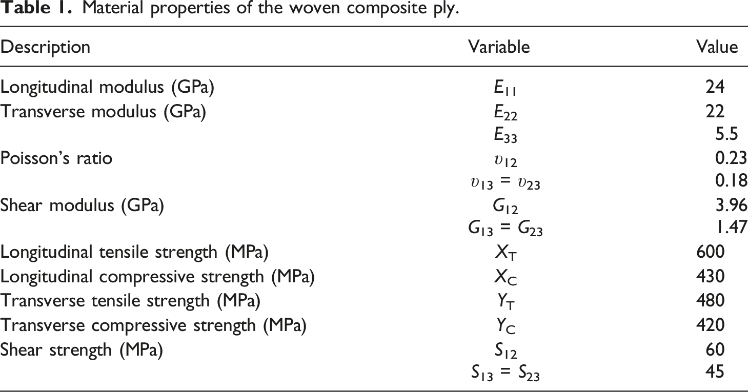
Material properties of the woven composite ply.
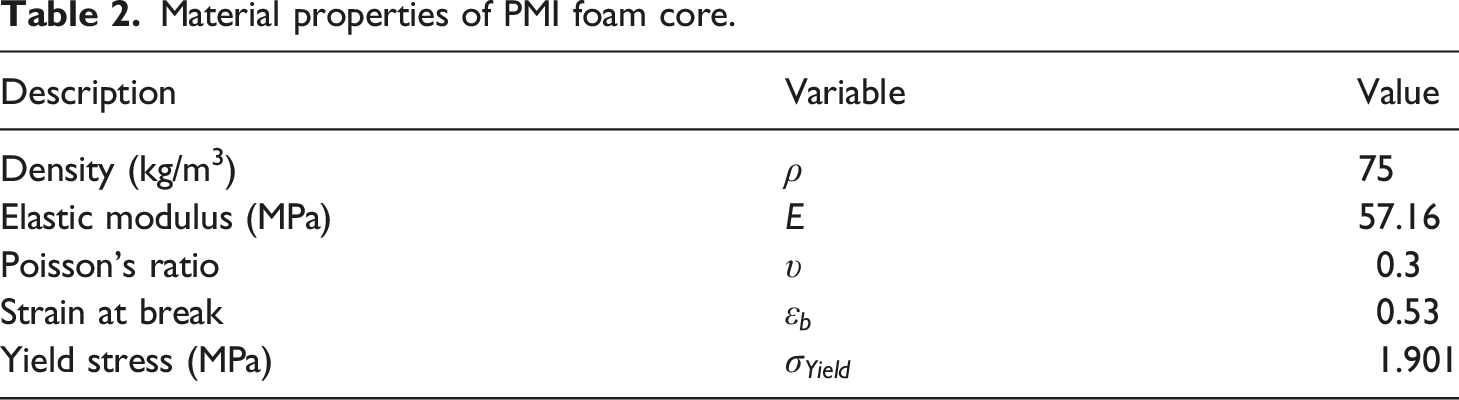
Material properties of PMI foam core.
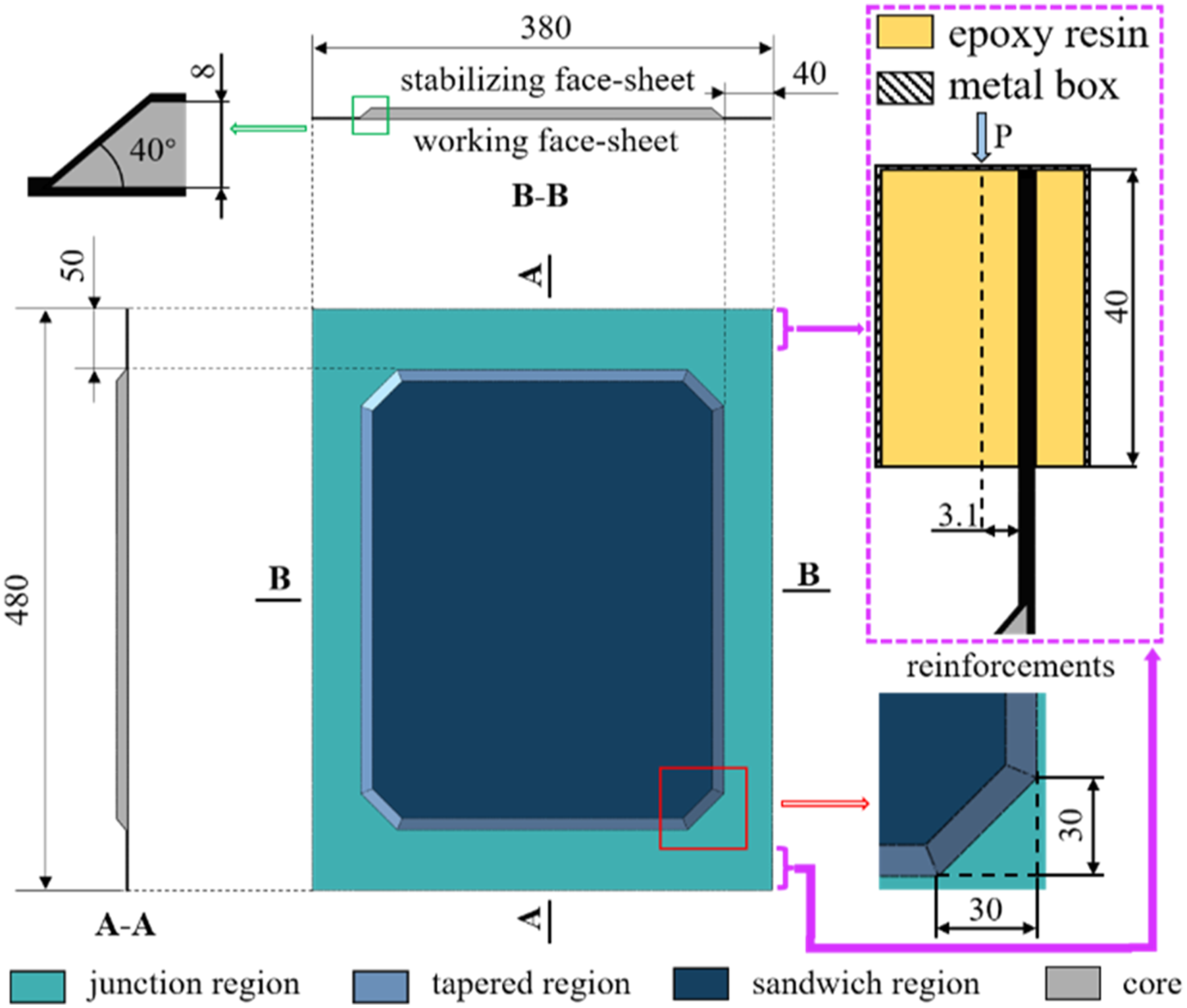
Schematic diagram of ASP specimen. (Geometric unit: mm).
Axial compression test set-up
The test setup employed for conducting uniaxial compression tests on ASP specimens is illustrated in Figure 2. Knife edge supports are placed on two side edges of the specimens to ensure the simply supported boundaries, starting 10 mm away from the top (constrained) edge to the bottom (moving) edge. The metal boxes at the top and bottom edges are securely fastened to the end supporting blocks affixed with knives by using bolt connections. The assembly is then placed in the MTS hydraulic testing machine to perform the quasi-static uniaxial compression test with the displacement loading rate (i.e., the speed of the loading end) of 0.5 mm/min. (a) Test setup for conducting uniaxial compression test of ASPs; (b) boundary conditions and details of FE model. (Geometric unit: mm).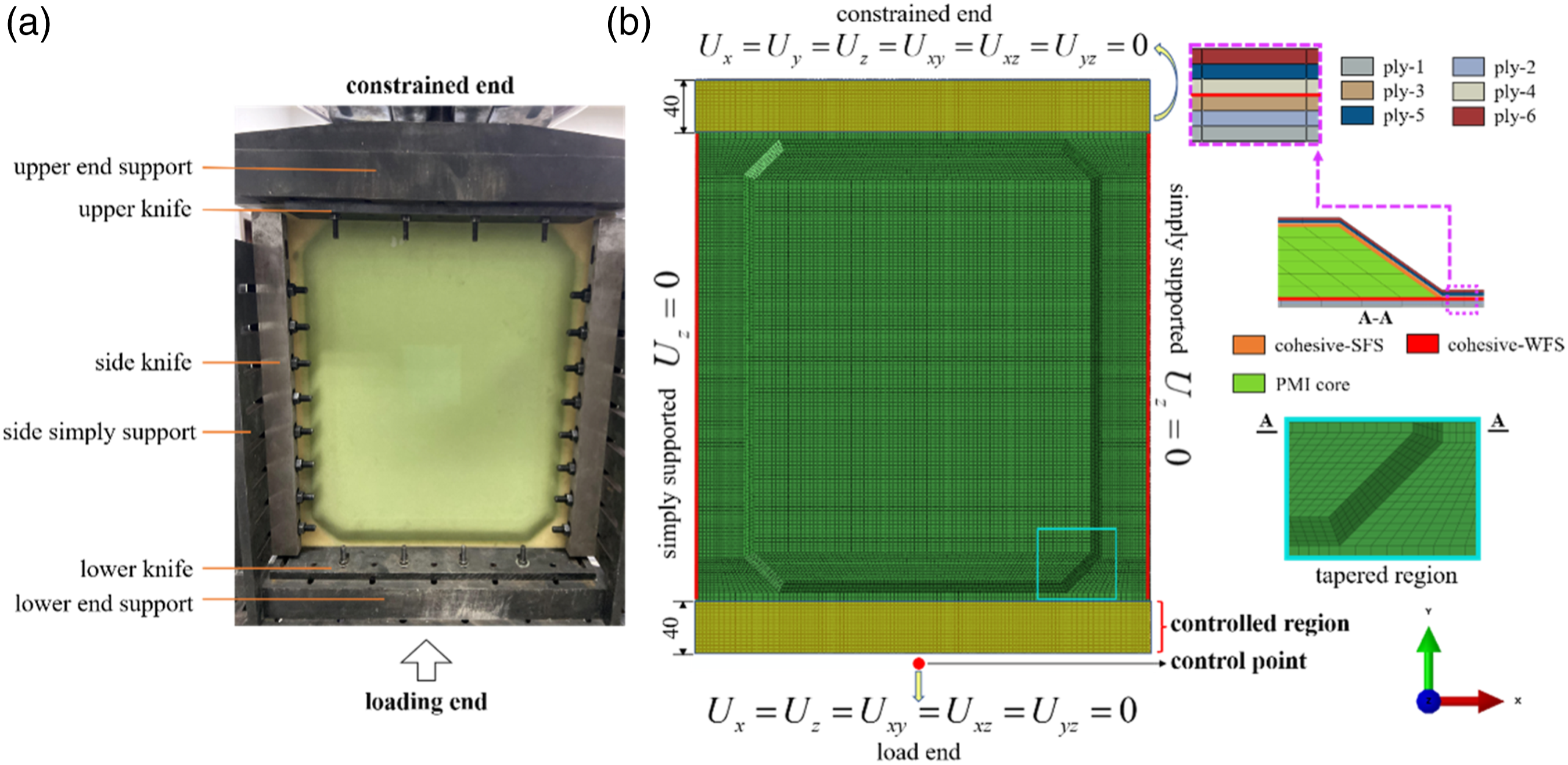
Conventional strain gages are employed to obtain strain distributions on Specimen-1 and Specimen-2, while ARAMIS 3D Camera Systems (DIC measure system manufactured by GOM) 22 is utilized to monitor the complicate mechanical behavior on Specimen-3.
Numerical analysis
Damages in the face sheets, PMI foam core, and the face-core interface are considered in the finite element (FE) analysis. And an energy-based approach is employed to simulate the damage evolution.
Progressive failure in composite
Damage onset
The damage initiation of the face sheet is determined with Hashin criterion modified for woven fabric laminates 23 and is defined by equations (1)–(4). Matrix damage is ignored, 24 and only the fiber damage in longitudinal and transverse directions is considered.
Fiber Longitudinal Tension Failure Mode (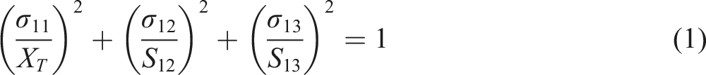
Fiber Longitudinal Compression Failure Mode (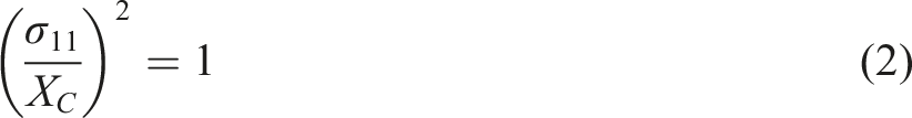
Fiber Transverse Tension Failure Mode (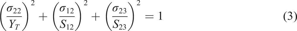
Fiber Transverse Compression Failure Mode (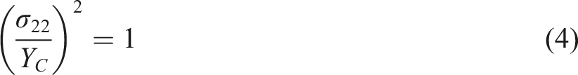
In equations (1)–(4),
Damage evolution
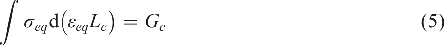
σ
eq
,
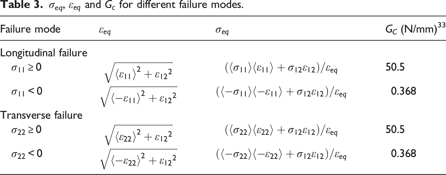
The damage variables 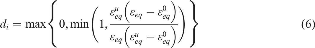
Element deletion is activated once both
The properties of degraded materials are given by.
Delamination
The traction-separation constitutive model is employed to describe the mechanical behavior of the cohesive interface between face sheet and the core, namely,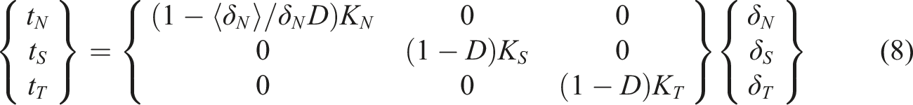
The quadratic nominal stress criterion is applied to predict the interface damage onset.
25
The criterion is given by.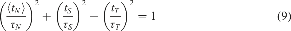
The damage evolution behavior is controlled by a bilinear softening law and can be determined by effective fracture toughness, defined using the BK criterion
26
as
Adopting the bilinear degradation law yields the damage variable D as follows,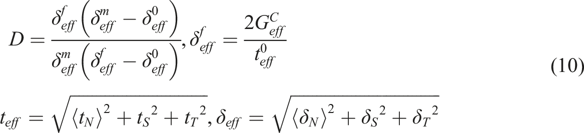
Cohesive properties used in numerical study.
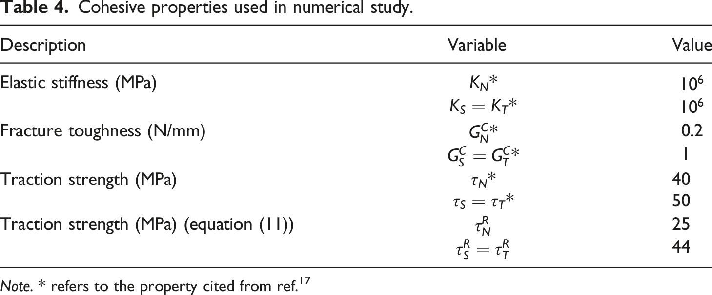
Note. * refers to the property cited from ref. 17
PMI foam core failure
The crushable foam constitutive equation
29
is employed to describe the elastic-plastic behavior of the core. The yield surface and flow potential of the crushable foam model with isotropic hardening depend only on the uniaxial compression behavior,
30
hence, the nominal stress-nominal strain curve of PMI foam is obtained by uniaxial compression test and shown in Figure 3. Nominal stress-nominal strain curve of PMI foam under uniaxial compression.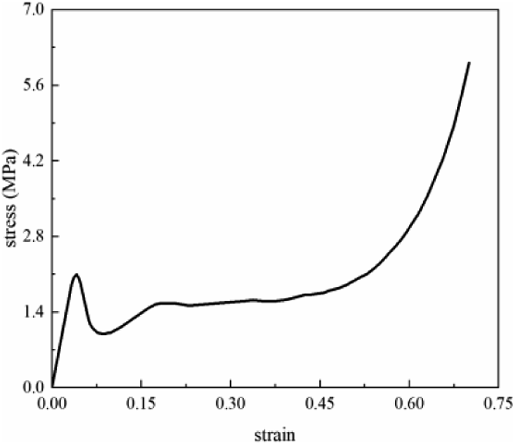
Since the core mainly bears shear load, shear damage is the main failure mode of the core.
17
Hence, shear damage model
31
is applied to predict the failure of PMI foam. The criterion for shear damage onset is given by.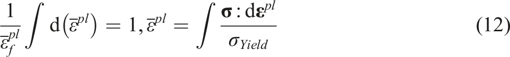
Finite element model
A VUMAT subroutine is developed within the ABAQUS/Explicit platform to analyze the mechanical behavior of sandwich panels subjected to compression. The non-linear FE model employs the exact geometric dimensions as the test specimens. As illustrated in Figure 2, the reinforced region at the constrained end is entirely fixed, while at the loading end, the control point constrains all degrees of freedom (DOFs) except for the translational DOF along the loading (y-axis) direction. The translational DOF along the out-of-plane (z-axis) direction of the two side edges is constrained. A separate mesh layer is applied to each ply of woven composite. The composites and core are discretized using C3D8R elements, while the face-core interface is modeled by COH3D8 elements with zero thickness. Moreover, a fine mesh is employed in the tapered region as shown in Figure 2(b).
Results and discussion
The damage mechanisms and failure of ASPs under uniaxial compression are analyzed using experimental observations and simulation results. And the influence of the taper angle on the mechanical behavior of ASPs is further investigated.
Experimental results and numerical predictions
The experimental strain-load responses of Specimen-1 and Specimen-2 are shown in Figure 4. The serial numbers in brackets represent the measuring points in the WFS. The sign change in slope can serve as an indicator of buckling.
17
Initially, the strains in WFS and SFS exhibit a linear increase with the applied load. After buckling, the strain-load curves in the SFS become non-linear. On the contrary, the curves for the measuring points in the WFS remain approximately linear. These results are consistent with the findings reported in reference,
17
confirming the validity of the conducted tests. Moreover, despite the back-to-back positions of the strain gages, noticeable variations are observed in the measured strains at identical points on both WFS and SFS before buckling occurs, such as strains at points 18 and 53. Although the variations in simulated strains at points 18 and 53 are less noticeable than the experiment ones, the simulated strain-load curves correlate well with experiment data, indicating that the deformed configuration is well predicted by the developed FE model. Strain-load curves and gage locations: (a) strain-load curves and (b) locations and serials numbers of strain gages. (Geometric unit: mm; the serial numbers in brackets mean the measuring points in WFS).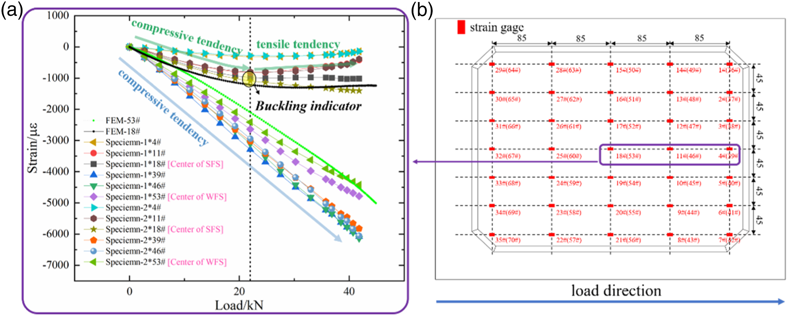
The out-of-plane displacement distribution of Specimen-3 on the WFS, obtained through 3D DIC measurement and numerical simulation, is depicted in Figure 5. The buckling mode of the ASP exhibits a half-wave pattern in the middle. The maximum out-of-plane displacements of the buckling mode of Specimen-3 are 9.065 mm in the test and 10.428 mm in the simulation. With the further increase of displacement load, the specimen experiences failure, accompanied by a noticeable bulge at the tapered region. Experimental out-of-plane deformation at (a) buckling and (b) failure; simulated out-of-plane deformation at (c) buckling and (d) failure. (Geometric unit: mm).
Figure 6 displays a comparison between the simulated and experimental load-displacement curves. Initially, the load-displacement curves exhibit linearity. With the increasing load, the curves deviate from linearity due to buckling, displaying enhanced nonlinearity as the load approaches the failure point. The ratio of the failure load to the buckling load is approximately two, indicating that ASPs can still bear a substantial load after buckling. The simulated results correlate well with the experimental data, with only 5.9% differences in buckling load and 2.9% differences in failure load. Additionally, the slight decline in the slope of the load-displacement curves during the post-buckling stage demonstrates the achievement of the “Buckle-Free” design, a concept proposed by Wu et al.,
32
for the test specimens. A comparison between the predicted and experimental load-displacement curves.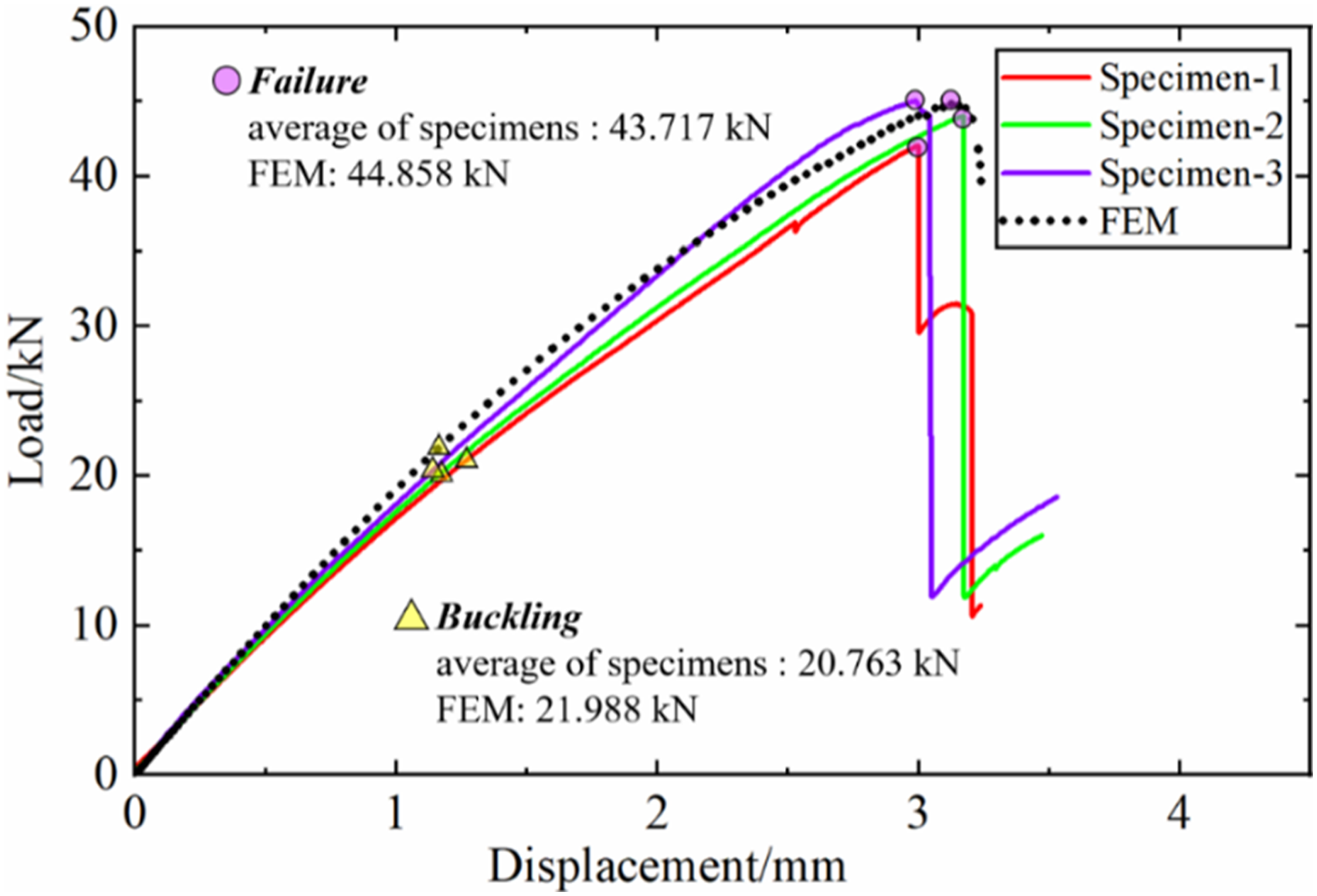
Figure 7 presents the failure modes observed in Specimen-2 alongside the corresponding simulated modes using the non-linear FE model. Extensive fiber breakages along the crack propagation direction indicate that fiber failure is the primary failure mode in the woven fiber-reinforced face sheets. Moreover, the crack propagates across the width direction on the WFS, forming a continuous fracture zone in the C-scan image. Localized damage is observed in the tapered region of the SFS. The crack exhibits a discontinuous pattern on the SFS. Additionally, the extent of longitudinal and transverse fiber breakage in the SFS of the junction region is comparable, as shown in Figure 7(b). In contrast, the transverse fiber breakage is significantly more severe than the longitudinal fiber breakage on the left side of the WFS, while the opposite trend is observed on the right side of the WFS, as shown in Figure 7(a). In summary, the dominant fiber failure mode shifts from longitudinal fiber to transverse one along the width direction of the specimens. Figure 7(c) demonstrates that the simulated results of the WFS can accurately capture the changes in fiber failure modes along the width direction. Failure mode of specimen-2 on (a) working face-sheet and (b) stabilizing face-sheet; failure mode of non-linear FE model on (c) outer-most ply on working face-sheet and (d) outer-most ply on stabilizing face-sheet; (e) C-scan on working face-sheet.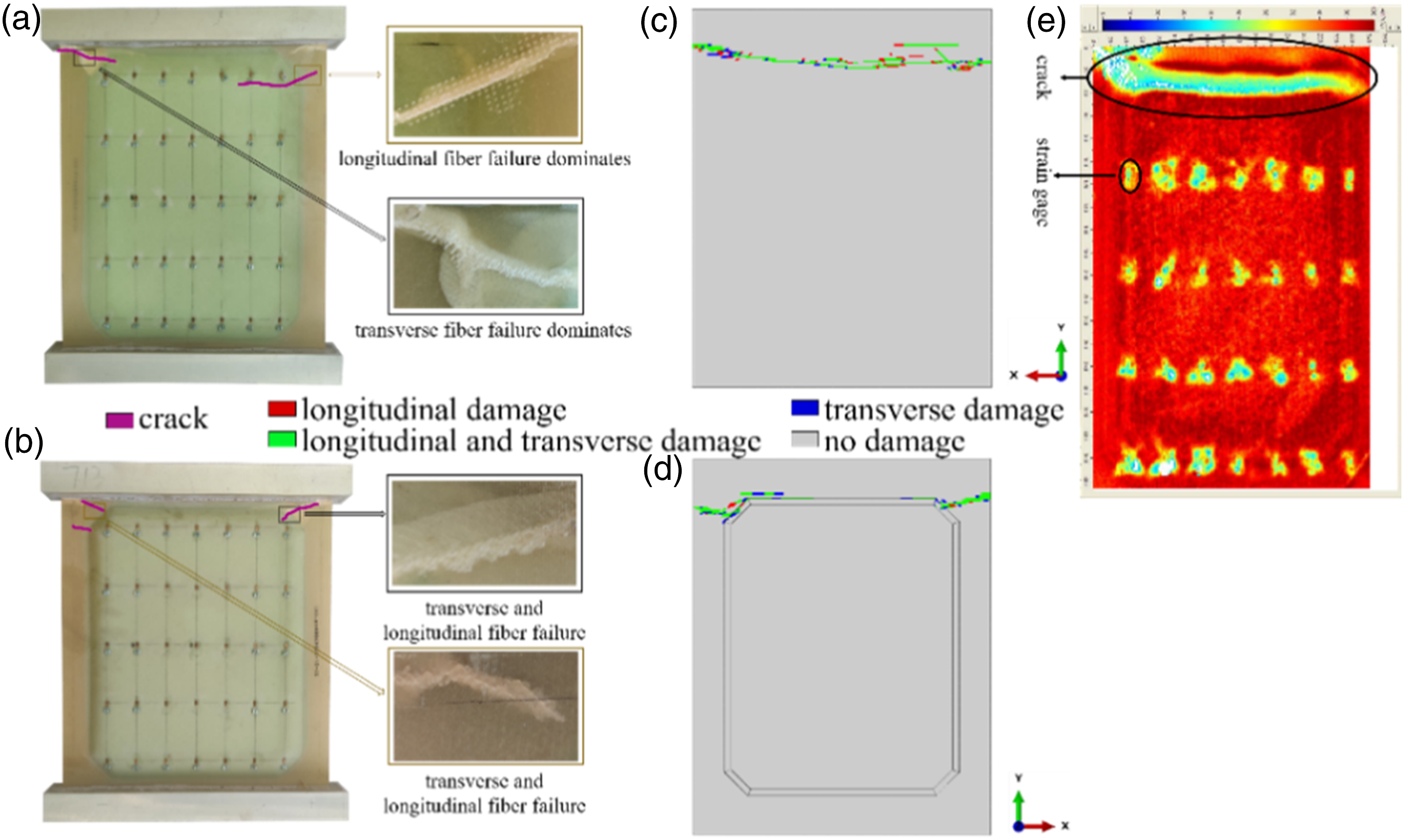
Failure mechanism analysis
Figure 8 depict the progressive damage processes on WFS and SFS, where symbol F represents the applied force, and the ply number in WFS and SFS is shown in Figure 2. Figure 8(a) shows the damage of WFS when F is 32.25 kN. The damage first occurs at ply-3 precisely on the boundary between the tapered and junction regions. The stress concentration resulting from the tapered region leads to the initiation of damage. Figure 8(d) shows the damage of SFS when F is 35.89 kN. The damage first occurs at ply-5, specifically at the boundary between the tapered and junction regions. A continuum crack along the width of the WFS in ply-2 is observed when F is 41.19 kN, as shown in Figure 8(b). The later initiated crack in ply-2 propagates faster than the one in ply-3. Comparisons of the damage initiation and crack propagation reveal that ply-2 bears the highest load among all plies. Figure 8(e) shows damages on SFS when F is 42.12 kN. Damages occur on both right and left sides of ply-6, but damage appears only on right side of ply-4 and ply-5. This observation suggests that the outermost ply of SFS bears greater loads than the remaining plies of SFS once damage occurs in ply-5. The failure state of WFS and SFS is illustrated in Figure 8(c) and (f), respectively. Each ply of WFS exhibits a continuous crack across the width of the ASP specimen, whereas such a continuous crack does not exist in the plies of SFS. This fact indicates that the WFS carries more load than the SFS. Damage on WFS when (a) F = 32.25 kN; (b) F = 41.19 kN; (c) failure; damage on SFS when (d) F = 35.89 kN; (e) F = 42.12 kN; (f) failure.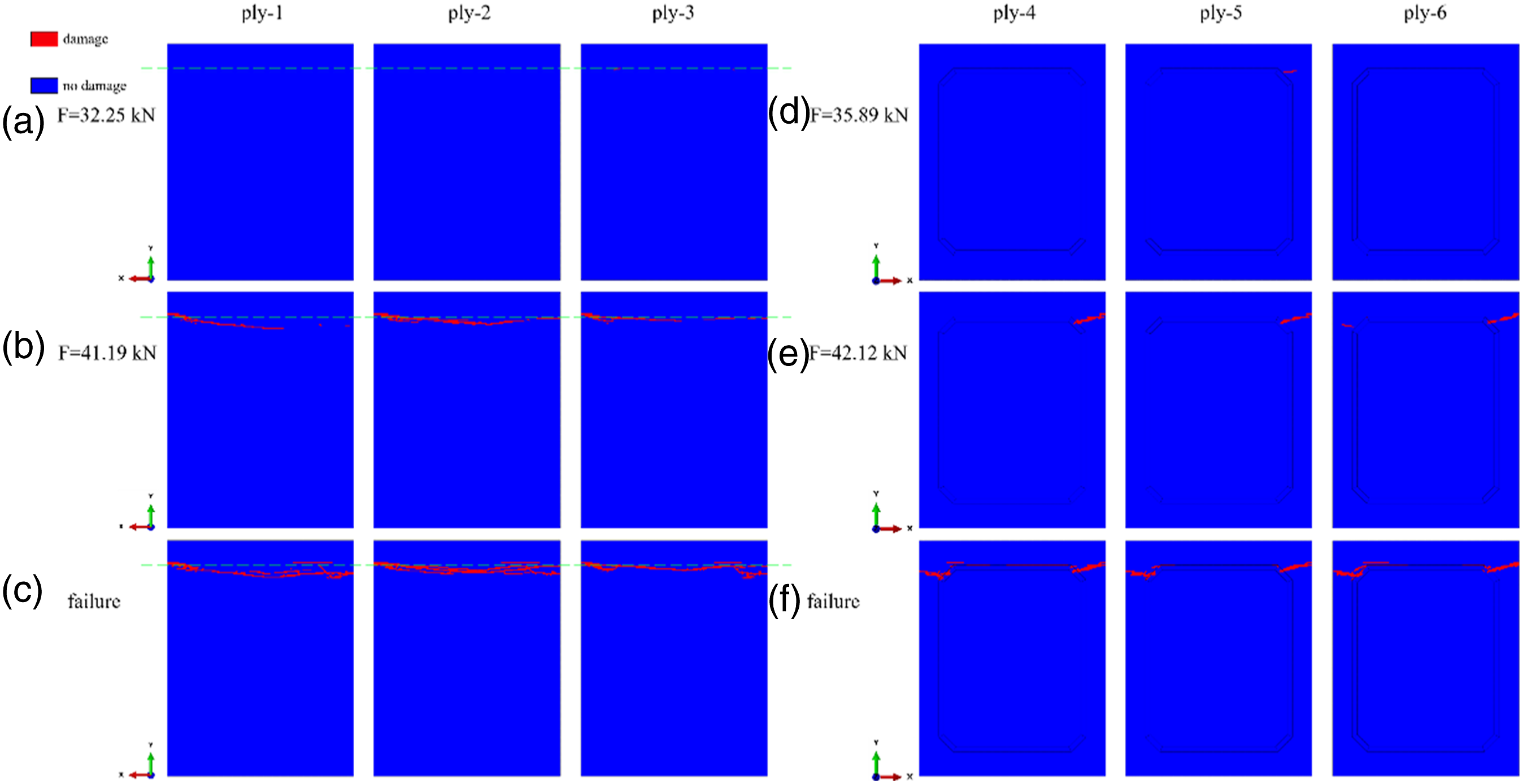
Figure 9 illustrates the simulated delamination occurrence at the face-core interface. Significant delamination is observed at the WFS-core interface under 42.12 kN load. As the load approaches the ultimate failure load, extensive delamination accumulates at the WFS-core interface within the tapered and sandwich regions, but relatively fewer damages are observed at the SFS-core interface. Figure 10 illustrates that damages predominantly accumulate in the core chamfers prior to the failure of sandwich structure, and the propagated crack connects the damaged areas in the two chamfers along the width direction. Delamination at the face-core interface (a) F = 42.12 kN; (b) F = 44.59 kN; (c) failure. Damage of PMI core when F is 44.59 kN from the view of (a) working face-sheet side; (b) stabilizing face-sheet side.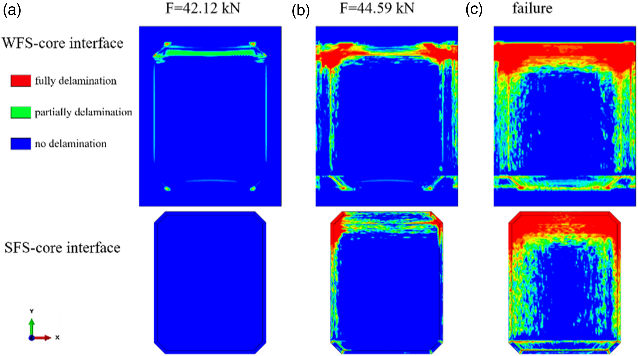
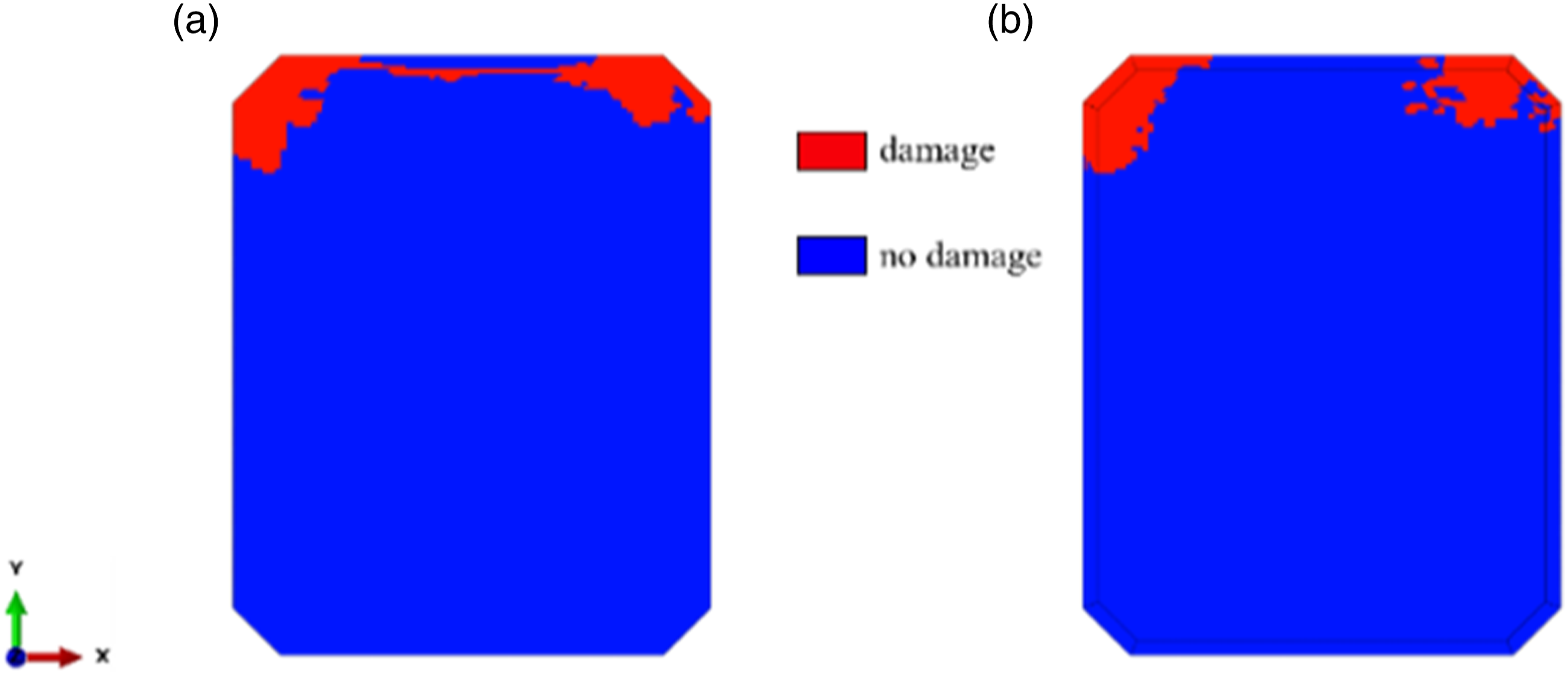
In summary, the uneven shape of the SFS and tapered region results in unequal load distribution between SFS and WFS. The damage is initiated in the innermost ply of WFS (ply-3) within the tapered region, leading to delamination at the WFS-core interface. Once delamination is initiated, the load is concentrated more in the undamaged area, which causes damage to the core and the junction region in SFS. These damages make the WFS carry a greater part of the applied load, intensifying crack propagation in WFS. The propagation of the crack in WFS worsens the delamination, which causes further damage to the core. The mutual influence process, i.e., the interaction among the damage in WFS, delamination, and damage in the core, can be described as the Damage Propagation Enhancing Loop (DPEL). The DPEL intensifies failure on each ply of WFS, ultimately triggering the complete crack formation and structural failure.
Parametric study
The effects of the tapered angle on the compression response of ASPs are numerically investigated based on the developed FE model and analysis. Two additional tapered angles, namely, 20° and 60°, are comparatively examined. The normalized buckling and failure loads (
Figure 11 illustrates the impact of the tapered angle on Normalized loads of ASPs with different tapered angles obtained by simulations.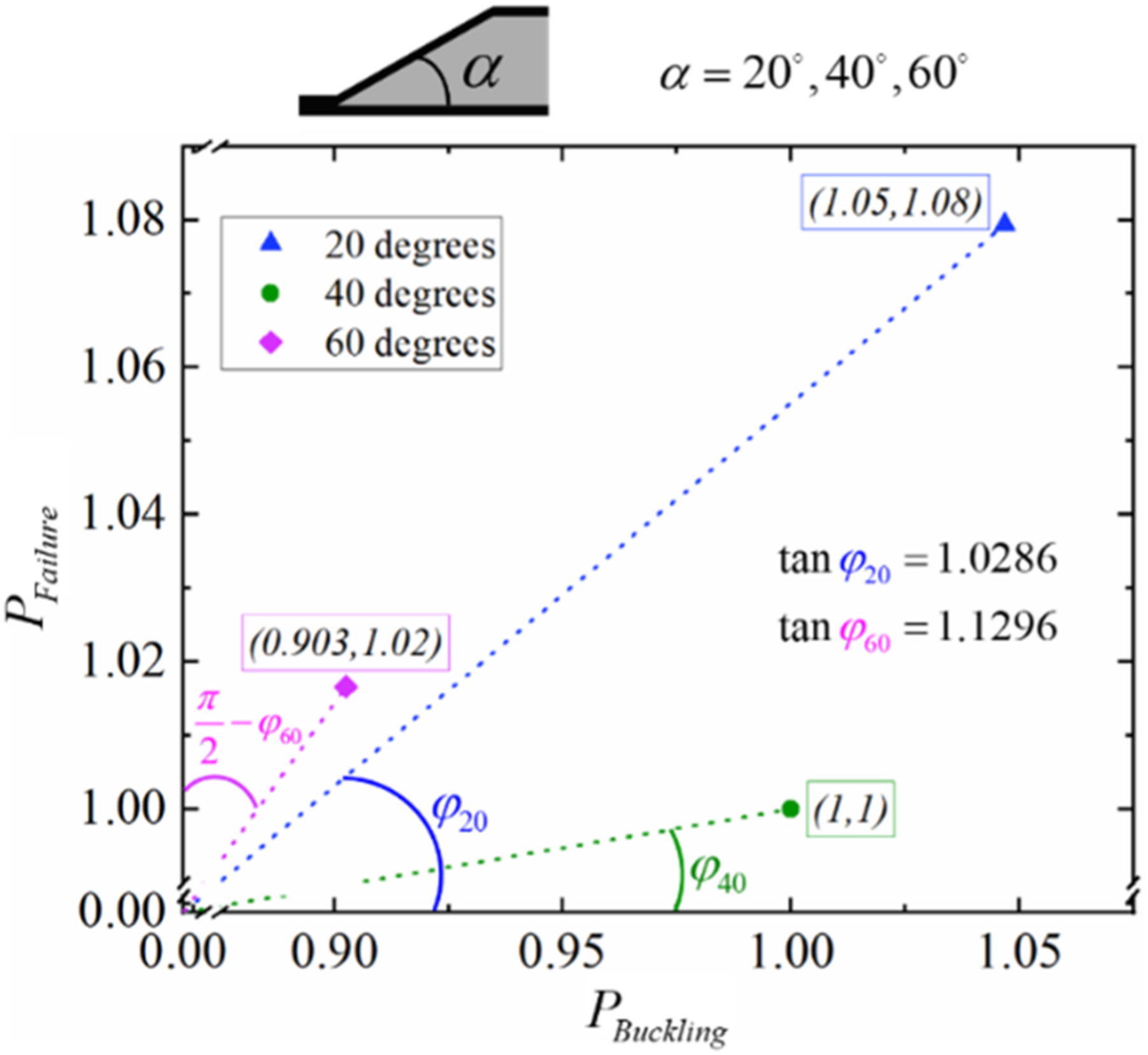
Conclusions
The mechanical behavior and failure mechanisms of asymmetric sandwich panels under uniaxial compression are comprehensively investigated. Quasi-static uniaxial compression tests are conducted. Experimental observations show that global buckling occurs in the asymmetric panels with a half-wave deformed configuration. A non-linear FE model is then developed to address details of the failure mechanisms. Consistency is attained comparing simulation and test data. According to the simulation, transverse cracks occur firstly in the middle ply of the working face sheet (i.e., the flat face sheet), underscoring the significance of the middle ply concerning the overall load capacity of asymmetric sandwich panels. Severe cracks are well captured in each ply of the working face sheet, indicating the failure of every single ply of the working face sheet leads to the final failure of the entire asymmetric sandwich panel. Furthermore, the sequence and correlation of delamination, face sheet and core failure modes, described by the proposed Damage Propagation Enhancing Loop, are revealed based on the developed FE analysis. Finally, the influence of the tapered angles on the mechanical responses of the panels under uniaxial compression is analyzed. Results show that an optimal tapered angle exists in order to output the high performance of the asymmetric sandwich panel. In this study, a tapered angle of 20° carries greater loads regarding the specimen configuration. And asymmetric sandwich panels with a tapered angle of 60° present better post-buckling performance.
Footnotes
Acknowledgements
The authors would like to gratefully acknowledge Fesher Aviation Component (Zhenjiang) Company Limited, China for supplying the test specimens.
Declaration of conflicting interests
The author(s) declared no potential conflicts of interest with respect to the research, authorship, and/or publication of this article.
Funding
The author(s) disclosed receipt of the following financial support for the research, authorship, and/or publication of this article: This work was partially supported by the National Key Basic Research and Development Program of China (Grant No. 2021YFF0501800); the National Natural Science Foundation of China (Grant No. 12002157), The Fundamental Research Funds for the Central Universities (No. NT2022001); and the Priority Academic Program Development of Jiangsu Higher Education Institutions.