
Abstract
This paper reports on the production and evaluation of a new class of “Z-axis” composite sandwich panel where the core consists of a dense array of vertically-aligned, 3 mm long E-glass fibre composite “beams”. The E-glass fibre bundles were aligned using electrostatic charging. A procedure was developed to retain the orientation of the short-fibre bundles whilst they were impregnated and cured with an epoxy/amine resin system. The skins were manufactured from 4-ply carbon/epoxy prepregs with a layup sequence of (0,90)s. The out-of-plane compressive strength of these Z-axis composites was found to be 25.2 and 15.2 times greater than equivalent sandwich panels made with Nomex® and aluminium honeycomb cores respectively. Their compressive strength was found to increase in proportion to the density of the core. Buckling and fracture of the vertically-aligned Z-axis composite were the predominant failure modes observed. The shear and flexural properties of the Z-axis composites were comparable to equivalent honeycomb sandwich panels manufactured from Nomex® and aluminium honeycomb cores.
Introduction
A sandwich composite panel consists of a lightweight core bonded to two stiff and strong reinforced outer skins. The skins are responsible for resisting the in-plane and bending loads whilst the function of the core is to resist out-of-plane compressive and shear loads. In applications where the sandwich panel is subjected to hydrostatic or compressive loading, the properties in the through-thickness or “Z-direction” are important [1]. A schematic illustration of selected designs of cores is shown in Figure 1.
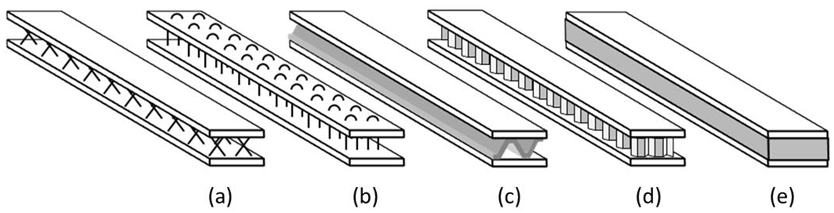
Schematic illustration of selected sandwich composites with specific core designs. (a) X-core Z-pinned core. (b) Stitched core. (c) Truss core. (d) Honeycomb core. (e) Foam core. Items (a) and (b) are sometimes used with a foam core.
Common materials that are used as the core include hexagonal honeycomb structures made from aluminium or Nomex® [2] as they offer high specific shear stiffness and strength [3]. The honeycomb structure provides a continuous path for shear loads to be transferred throughout the core. Polymeric and metallic foams are also used as the core in sandwich structures. Polymer-based foams tend to have a lower density than the honeycomb structures and offer excellent energy absorption characteristics. However, their specific compressive strength and stiffness are typically lower than the honeycomb structures [4]. Reinforcing fibres have been used as an alternative to honeycomb and foam-based cores. One such example is the “X-core” sandwich panel where elongated Z-pins were inserted through both skins prior to cross-linking the resin [5]. Cores have been manufactured consisting of Z-pins or combined with a foam where the X-core/foam panels are slightly heavier but exhibit better compressive properties [6]. The compressive properties were observed to be a function of the volume fraction and orientation of the Z-pins [5,7].
Stitching has also been used to introduce through-thickness reinforcement in preforms prior to impregnation and cross-linking of the matrix [8]. In a more recent development, the stitching process was modified to form a sandwich panel core consisting of composite columns [9]. The compressive strength was observed to increase linearly with the density of the stitched column. The stitching technique has also been adapted for the production of sandwich panels. For example, corrugated glass fabrics were stitched to the face-sheets [10–12]. Trusses have been used to form the core [13] and they have been reported to have similar compressive strength, for a specified density, when compared to aluminium and Nomex® honeycombs [3,14].
Other examples of innovation in the design of sandwich cores include shear-keying [15], tube-reinforced foam [16], composite rods [17], polymer/resin pins [18–20] and hybrid divided cores [21].
The current paper reports on a method to manufacture a new class of sandwich composite where the core consists of a dense array of vertically-aligned 3 mm long E-glass fibre bundles. The alignment of the E-glass was achieved using electrostatics and this class of sandwich design was termed “Z-axis composite”. Details of the experimental methods that were used to manufacture the Z-axis preform are described along with the procedures that were used to bond and impregnate the vertically-aligned short-fibres. The flatwise compression, flexural and transverse shear properties were evaluated and compared with sandwich composites manufactured using equivalent Nomex® and aluminium honeycomb cores. A brief description of the theory for the electrostatic-based levitation of short E-glass fibres is presented. The flatwise compressive strength of these Z-axis composites was found to be approximately twenty-five and fifteen times greater than equivalent sandwich composite panels made using Nomex® and aluminium honeycomb cores respectively.
Experimental
Materials
The resin systems selected had to fulfil a number of criteria. In the first instance, it was necessary for the vertically-aligned short-fibre preform (on an adhesive-backed cellulose paper) to be bonded to the composite skin. The selection criteria for this resin system was that it needed to enable the spatial orientation of the vertically-aligned fibres to be secured to the skin relatively rapidly. The other options considered were: (a) photo-curable resins; (b) conventional resin films that are used to bond honeycombs to composite skins; (c) the primary resin system that was used to impregnate the short-fibre preform; and (d) rapid-curing thermosetting resin systems. The two resin systems that were selected were Araldite-Rapid and Scotch-Weld 9323 where their pot-lives are approximately 5 and 120 minutes respectively. Both these resins are in the form of a relatively high-viscosity paste and hence, the probability of them wicking down the short-fibres was remote. The wicking of the resin will not be an issue if the same resin system, as that used to secure the vertically-aligned fibres, is also used to impregnate the short-fibre preforms. Araldite-Rapid was convenient because of its relatively short pot-life and rheological properties. Scotch-Weld 9329 was used to demonstrate that: (a) the Z-axis composite could be manufactured using high-performance structural adhesive with a relatively long pot-life; and (b) the mechanical properties of the sandwich composite could be optimised by the choice of adhesive. The primary resin system that was used for impregnating the vertically-aligned short-fibre preform was LY3505/XB3403. This resin was used as it has been characterised extensively by the authors previously with regard to its thermo-mechanical and spectral properties [24], impregnation characteristics [25], susceptibility to moisture ingress [26] and its cross-linking behaviour [27].
Sandwich panels
In the first series of experiments, Araldite-Rapid, a 2-part resin (Huntsman Advanced Materials, UK), was used for bonding the Z-axis preforms and the honeycombs to the carbon fibre composite skins. In subsequent experiments, the Z-axis preforms and the honeycomb were bonded using a high-performance adhesive (Scotch-Weld 9323, 3M, UK) [30].
The same epoxy/amine resin system, (LY3403/XB3503, Huntsman Materials, UK), was used to impregnate the array of vertically aligned short-E-glass fibre bundles [31].
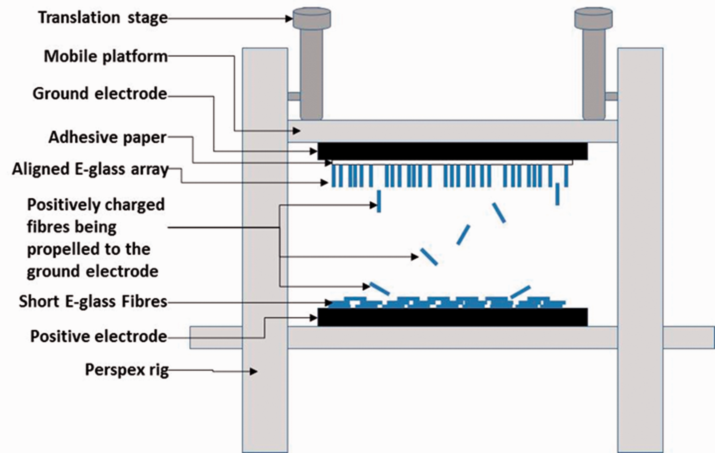
Schematic illustration of the electrostatic rig for producing the Z-axis E-glass fibre preforms.
The electrical potential was applied in cycles of 4 minutes, with a dwell period of two minutes without the applied voltage. This allowed the charge on the short-fibres to dissipate between cycles. This procedure was observed to increase the number of short-fibres leaving the positive electrode when the electrical potential was reapplied. During production involving longer cycles, some chaining was observed where the fibres were linked together as opposed to being deposited on the adhesive layer. A ground-electrode was used to discharge the rig at the end of the dwell period and then an insulating rod was used to dislodge any fibre chains. This resulted in a dense layer of vertically-aligned short-fibres on the adhesive layer. The number of cycles used was dependant on the spatial density of short-fibres that was required for the core.
After the desired fibre volume fraction of the short-E-glass fibres was deposited on the adhesive-backed cellulose paper, it was demounted from the rig. In the first series of experiments, a thin layer of an epoxy/amine adhesive (Araldite-Rapid) was applied to a pre-abraded and de-greased surface of the 4-layer cross-ply carbon fibre composite skin. The free-ends of the vertically aligned short-fibre array on the cellulose paper was positioned carefully on the composite skin with the adhesive layer. A flat steel plate was placed on the top along with a 2 kg weight to apply a lateral force during the bonding operation. The adhesive was permitted to cross-link for thirty minutes at ambient temperature. Once the short-fibres were bonded to the carbon fibre composite skin, the cellulose paper was removed. Photographs showing the production of Z-axis composites are presented in Figure 3(a) to (d). An optical micrograph of a short-E-glass fibres is shown in Figure 3(e) where the chopped (as-manufactured) fibre-ends are seen to be near parallel.
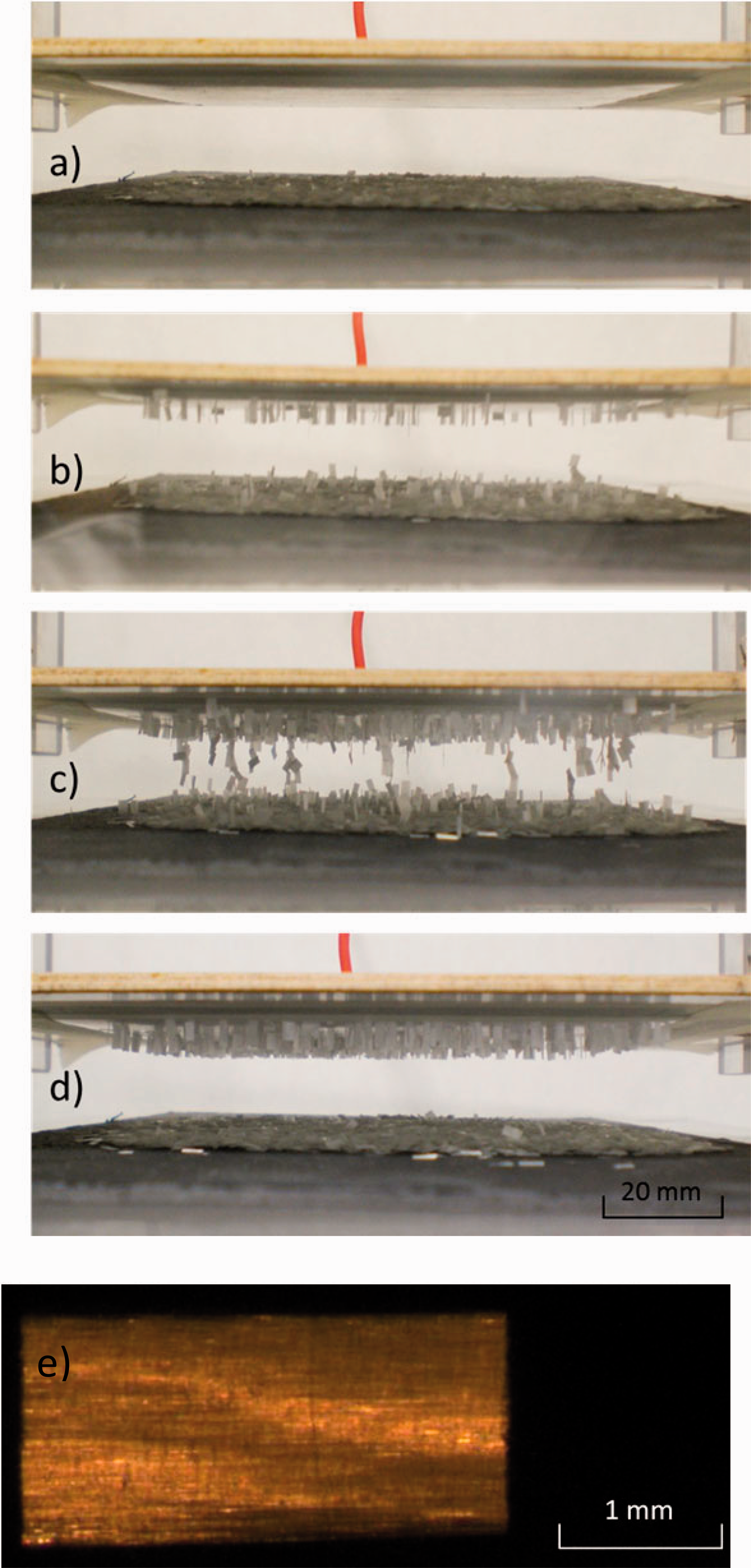
Photographs illustrating the production of the Z-axis preforms using an electrostatic field for deposition of the short-E-glass fibres. (a) A specified mass of pre-dried short-E-glass fibres is positioned on the positive electrode. (b) The application of an electrical potential results in the short-fibres being attracted to the grounded electrode. The adhesive paper retains the spatial orientation of the short-fibres on it. (c) Illustration of fibre chaining with prolonged application of the potential. (d) End of the production cycle where an array of vertically-aligned short-E-glass fibres are produced. (e) A magnified micrograph of a single short-E-glass fibre bundle.
Test methods
Results and discussion
Levitation of short E-glass fibres using electrostatics
A schematic illustration of the levitation of a short-E-glass fibre, under an applied electric field, is shown in Figure 4. The following section presents a brief description of the mechanism responsible for the levitation of the E-glass fibre. A summary of the relevant equations is also discussed.
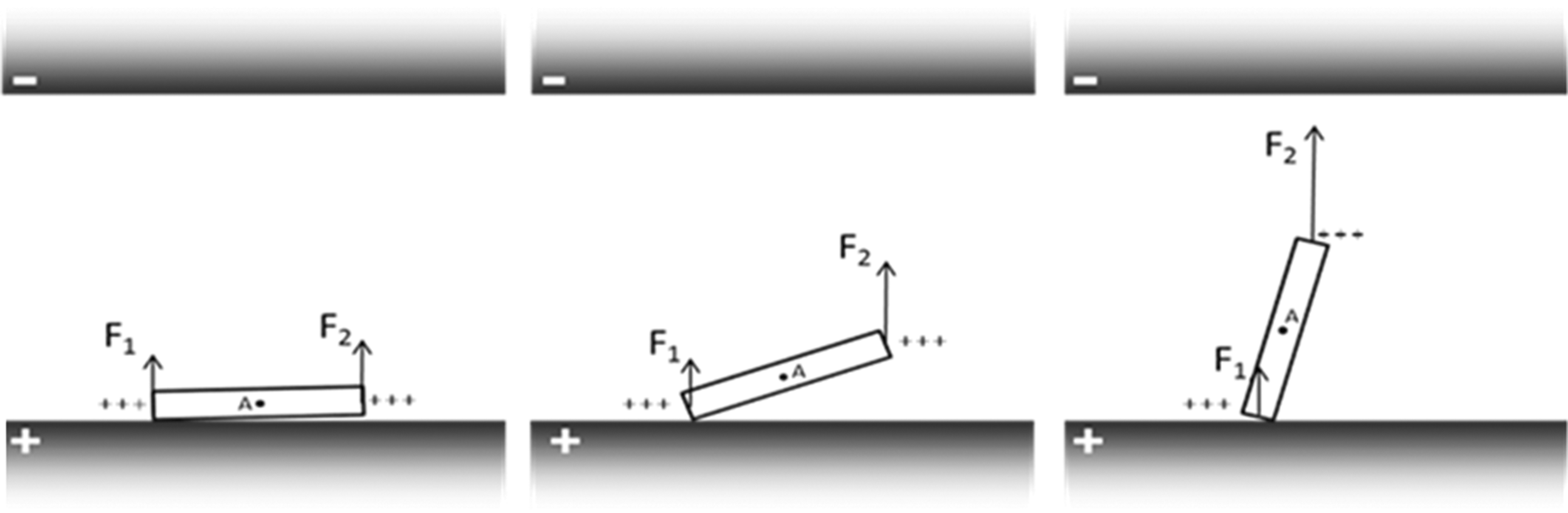
Schematic illustration of the electrostatic orientation of an E-glass fibre bundle. The accumulation of charge is non-uniform due to end-face topology of the chopped fibre-ends, the distribution of the binder within the bundle and its position (resting on other short-E-glass fibres – not shown). When an electric field is applied, the accumulation of charge is greater at one end and hence the magnitude of the force F2 is greater than F1. Hence, an initial orienting torque around point-A. The end of the fibre is lifted towards the grounded electrode.
E-glass is a dielectric material and its electrical conductivity and static dielectric constant are 10−14 S/m and 6.13 respectively [36]. The corresponding characteristic time-constant for charge dissipation, the ratio of permittivity to the conductivity, is 36.78 x 10⁴ s. In general, the composition of the sizing and binder formulations used on the fibres are proprietary. The antistatic agents used in the binder are generally meant for dissipating the static free-charge on the bundle in a significantly shorter time [37]. In the current study, the higher conductivity of the binder due to the presence of antistatic agents, along with other additives, aids in the flow of charges from the positively charged bottom electrode to the short-E-glass fibre bundles. Polarisation-induced bound charge also appears on the dielectric E-glass fibres. The polarizability in a static DC field is proportional to the electric field strength and it is greater for materials with larger dielectric constant. However, the polarization-induced surface bound charge density (
The following section gives a mathematical interpretation of the electrostatic charging and the effect of forces on the fibre bundles.


The electric field due to a continuous volume charge distribution
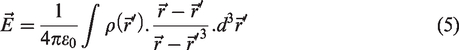
If a continuous charge distribution
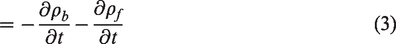
In the case of a charged fibre bundle with a charge distribution

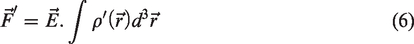
‘V’ and ‘d’ are the potential difference and the electrode separation respectively, with a uniform field ‘V/d’ in between. Therefore, the charge distribution of the fibre bundle determines the resulting motion. Due to inherent inhomogeneity in the binder distribution and the topography of the chopped end-faces of the fibre bundles, the charge distribution at the ends will be asymmetric. Therefore, the ends of the bundle will experience unequal forces (F1 and F2) of attraction towards the grounded electrode. The resulting torque induces rotation about the end with lower charge density until the bundle stands vertically on the bottom electrode. Subsequently, the bundle levitates vertically and adheres to the adhesive-backed cellulose paper on the grounded (top) electrode. The torque can be expressed as

δQ1 and δQ2 are the fractional charges at either ends of the bundle of length L and θ is the angle between length L and F2. Therefore, the bundle experiences rotation about the end with lower charge (δQ1) until it is aligned along the field. As the bundle stands vertically with the δQ1 end in contact with the bottom electrode, the force of attraction on the δQ2 end increases according to the Coulomb’s inverse square law, as it is closer to the top grounded electrode. In Figure 4, if the sum (F1+F2) acting along the same direction towards the top grounded electrode exceeds the weight ‘mg’ of the bundle, then it accelerates towards the top grounded electrode in a vertical fashion. Here, the effect of viscous drag in air is neglected as the frontal area of the bundle is small. The resultant of the forces on the bundle upon impact with the adhesive on the grounded electrode in conjunction with its topographical variations and mass distribution determine the orientation with respect to the electric field direction.
Comparison of mechanical properties
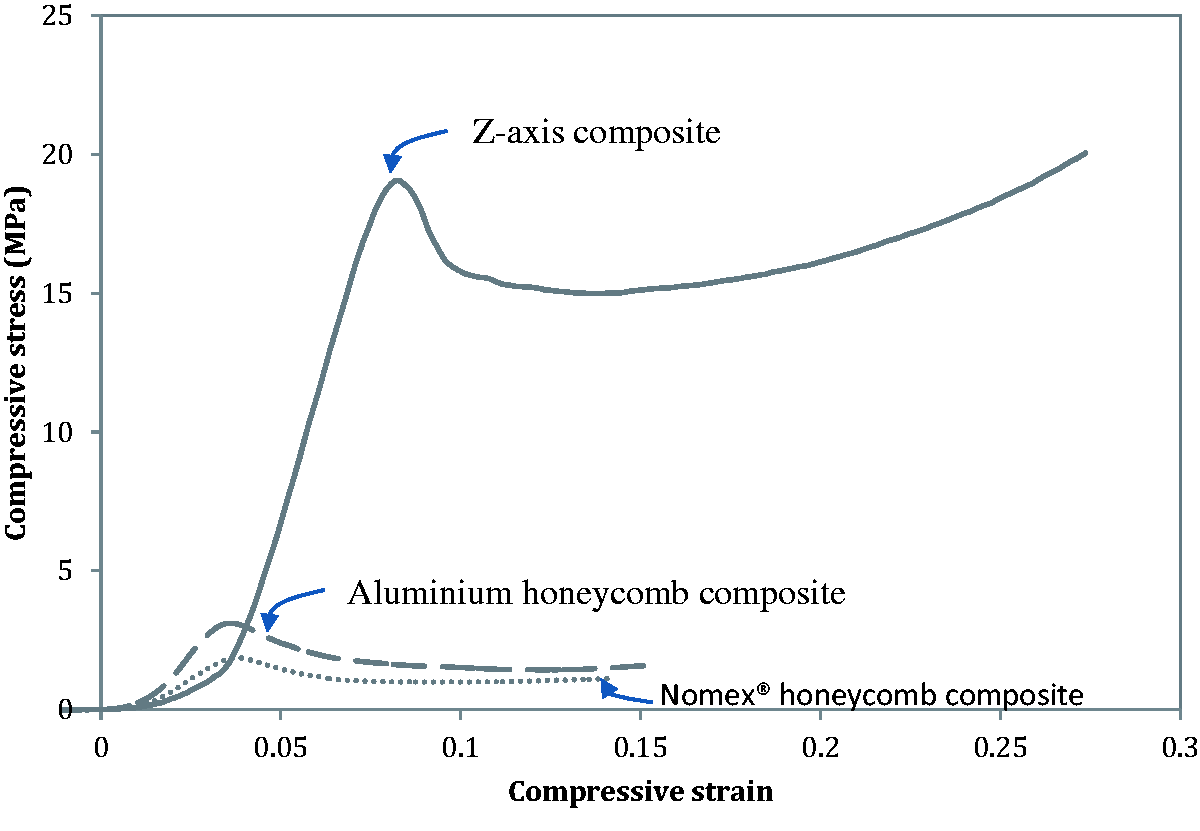
Typical stress/strain traces for the Z-axis, Nomex® and aluminium core sandwich composites.
A summary of the flat-wise compressive strength for the Nomex® aluminium honeycomb sandwich and the Z-axis composites is presented in Figure 6. Batch-1 refers to the un-impregnated short-fibre Z-axis cores where the mean compressive strength was 1.04 MPa. The term un-impregnated refers to the case where the short-fibre arrays were not coated with the resin and cross-linked. The mean compressive strengths of the aluminium and Nomex® honeycomb sandwich panels were 3.15 and 1.91 MPa respectively. The compressive strengths stated by the manufacturer for the aluminium and Nomex® honeycombs are 3.93 MPa and 2.4 MPa respectively.
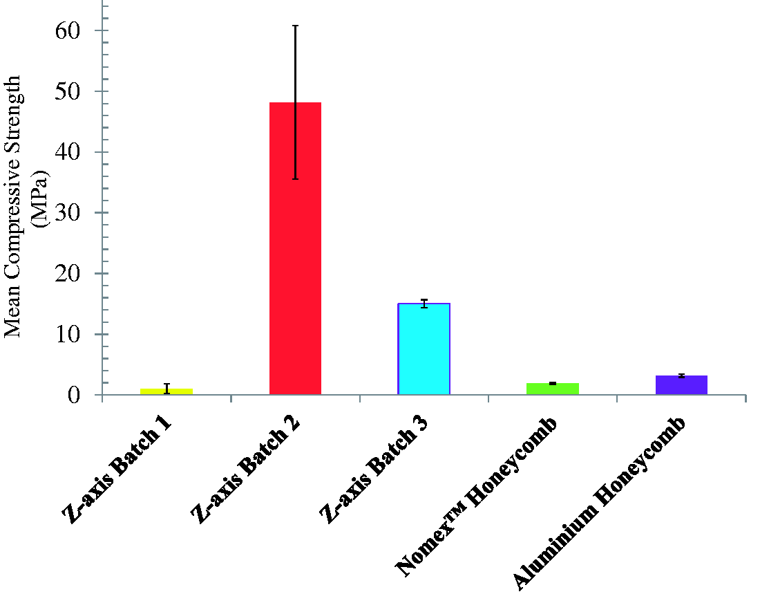
The mean compressive strengths of the 50×50 mm sandwich composites. Z-axis batches 1-3 correspond to un-impregnated, impregnated and controlled-mass samples where the total weights of the samples were equivalent to that of the Nomex® and aluminium honeycomb sandwich composites.
Figure 6 shows that the flatwise-compressive strength for Z-axis batch-2 (impregnated short-fibres and the matrix was cross-linked to produce the composite) is significantly superior to its conventional sandwich honeycomb counterparts. The average compressive strength of the Z-axis composite is 25.2 times that of Nomex® and 15.2 times that of aluminium. The average mass of the Z-axis batch-2 samples was only 1.31 and 1.28 times heavier than the equivalent Nomex® and aluminium honeycomb sandwich composites respectively.
On inspecting Figure 6, it is apparent that Z-axis batch-2 composites exhibit a relatively large variation in the compressive strengths. This is despite the fact that the total weight of the short-fibre bundles in the core was controlled for batch-2. This scatter in the flat-wise compressive strength observed in the Z-axis data may be attributed to one or more of the following factors: The variation in resin content between the samples. The mode of impregnation used in the current study relied on capillary action. Although the binder content in the short-E-glass fibre bundles was not determined, previous studies have shown that it can be variable. Hence, the impregnation efficiency may not have been uniform. The degree of impregnation is important as the matrix not only enables the creation of vertically-aligned beams of Z-axis preforms but it also provides significant lateral confinement and restraint for the short-fibre when subjected to compressive loading. In this proof-of-concept study, the binder system on the short-E-glass fibres used in this study was formulated for thermoplastic-resins. Therefore, the interfacial bond strength between the fibres and the matrix was not ideal. Nevertheless, it was sufficient to demonstrate the Z-axis sandwich composite concept.
With reference to the average mass of the Z-axis batch-2 samples mentioned previously, in weight-critical applications, this increased weight may not be a favourable proposition. Therefore, further Z-axis composite samples were manufactured and coded as batch-3. In these samples, the primary aim was to match their weights to that of the Nomex® and aluminium sandwich composites. These lighter Z-axis composites displayed lower compressive properties when compared to batch-2 primarily due to the reduced fibre and resin contents. However, compressive strengths were still significantly higher than the Nomex® and aluminium honeycomb core samples. The standard deviations for batches-2 and 3 were 12.6 MPa and 2.3 MPa respectively. This suggests that the Z-axis fibre content, orientation and impregnation efficiency has a major influence on the flatwise compressive strength and controls the consistency of the Z-axis composite.
Figure 7 illustrates the flatwise compressive stiffness for the different types of sandwich composites manufactured in this study. As expected, the un-impregnated samples (batch-1) had poor compressive stiffness when compared to the other sandwich composites. However, as seen in Figure 7, batches-2 and 3 exhibit improved compressive stiffness when compared to the Nomex® and aluminium core sandwich composites. The batch-3 samples had a mean compressive stiffness that is 8.03 and 4.67 times greater than the Nomex® and aluminium core sandwich composites respectively.
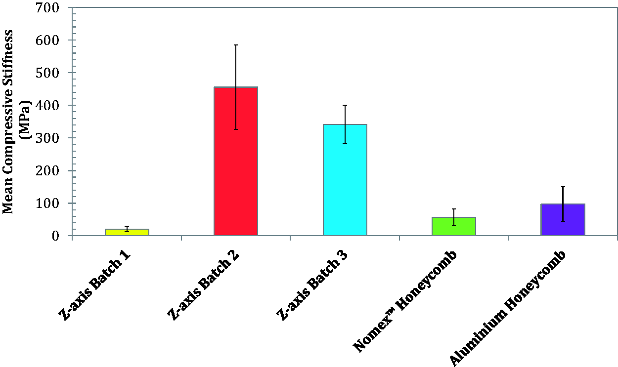
The mean compressive stiffness of Z-axis and honeycomb sandwich panels.
As mentioned previously and with reference to Figure 6, the scatter in compressive strength for batch-3 was reduced when compared to batch-2 when the resin content was controlled. In order to investigate this further, additional Z-axis composite samples were fabricated where the fibre content was maintained constant but the weight of the resin was varied. Figure 8(a) shows the relationship between resin content and the compressive strength for the Z-axis composites where a good correlation is observed between the two parameters. A similar trend is observed for the compressive stiffness as a function of the resin content illustrated in Figure 8(b). Visual inspection of the samples indicated that three factors may have been responsible for the trend in the data. Firstly, when the resin content was intentionally low, it was observed that the bonding between the vertically-aligned fibre bundles and the composite skins was not consistent and some resin depleted areas were observed. Visual evidence for this is presented in Figure 9(a) to (d). In Figure 9(a) a minute gap was seen between the bottom composite skin and the end of the vertically-aligned fibre. As the compressive load was applied (Figure 9(b)), the fibre was still unloaded. It made contact with bottom composite skin after an applied strain of 0.4 (see Figure 9(c) and (d))
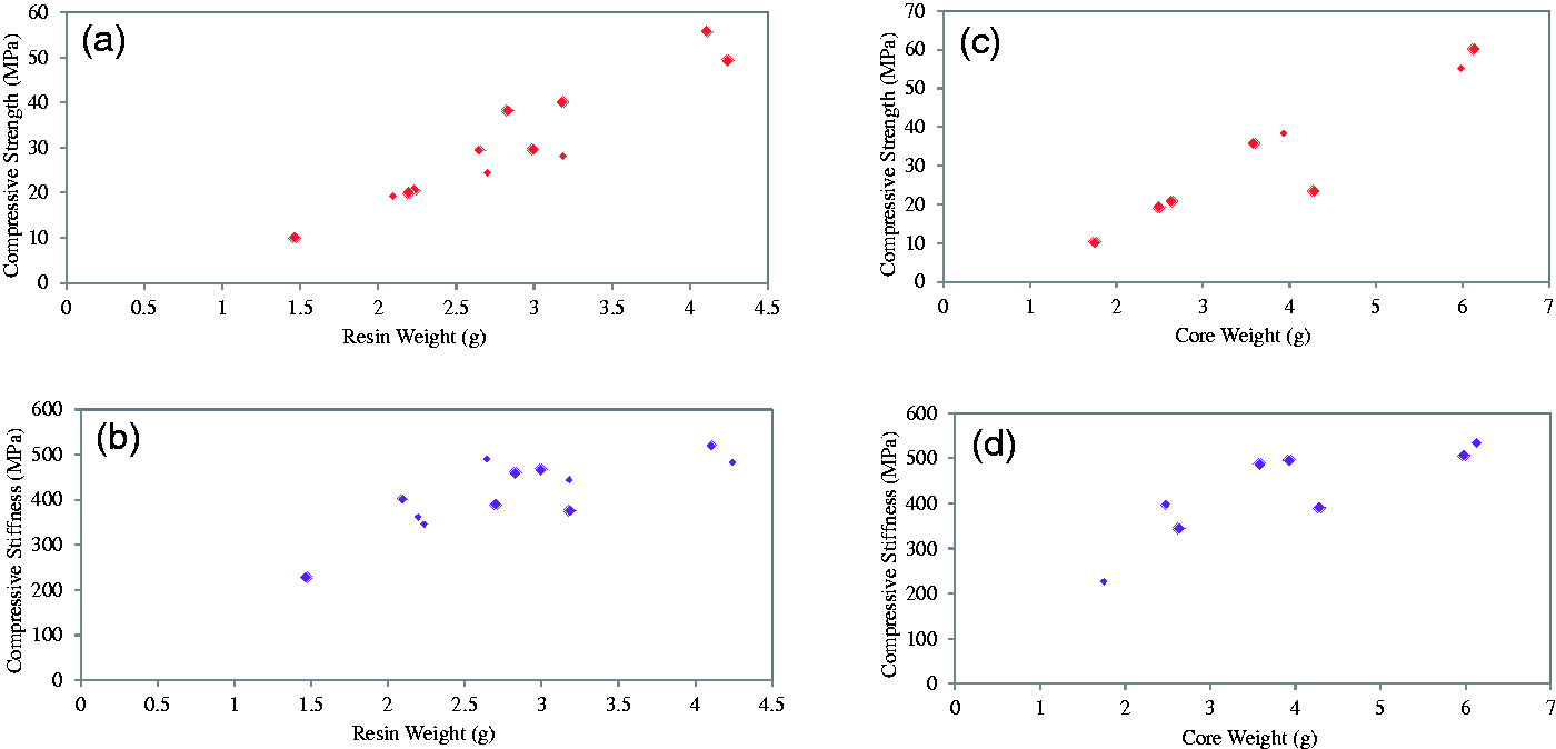
Effect of the resin and fibre core content on the compressive strength and stiffness: (a) compressive strength versus resin content; (b) compressive stiffness versus resin content; (c) compressive strength versus the weight of the Z-axis fibres in the core; and (d) compressive stiffness versus the weight of the Z-axis fibres in the core.
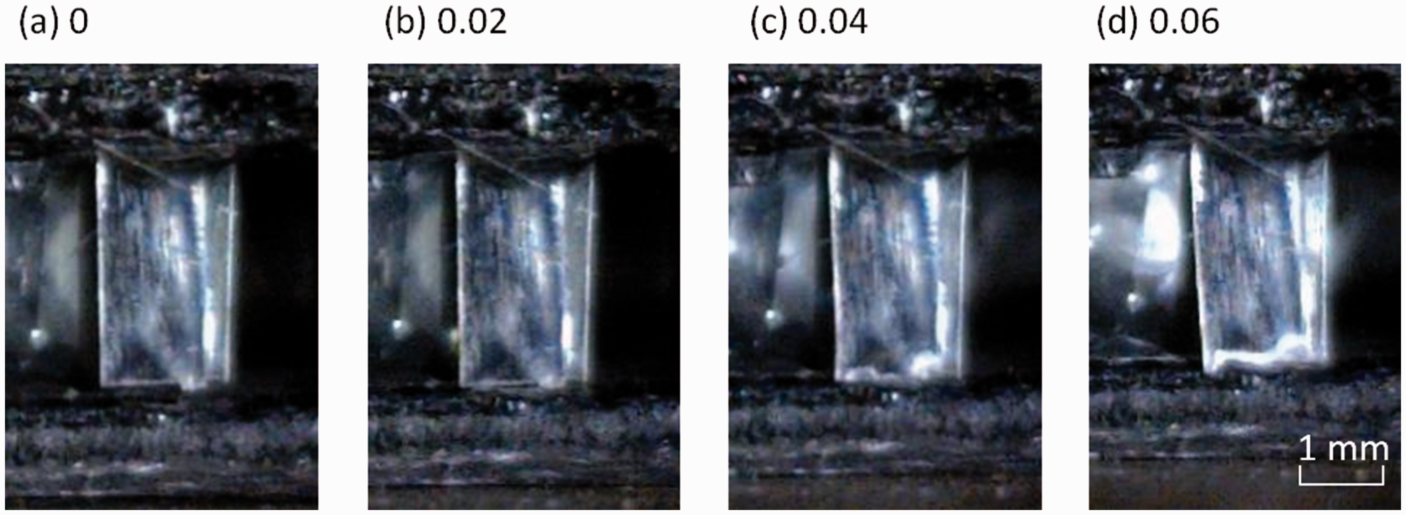
(a to d) Real-time imaging of a single-fibre bundle within a Z-axis composite, during compression testing where the resin content was made intentionally low. The numbers on the top of each image corresponds to the compressive strain on the sample when each image was acquired. A minute gap can be seen at zero strain where the fibre bundle is not in contact with the bottom skin. Contact between the fibre bundle and the composite skin is made at an applied strain of 0.04.
Secondly, in the samples where the resin content was intentionally low, as expected, sections of un-impregnated fibres were observed. Thirdly, in the composites with a low resin content in the core, a significant proportion of the fibre bundles buckled during compressive loading. However, in the samples with a higher resin content, where the impregnation was complete, fibres failed predominantly by fracture. Previous researchers have also proposed that the resin can act as a support against buckling. For example, polymer foams were reported to increase the buckling strength of Z-pins [5,6]. X-cores with thicker columns tended to fracture whilst thinner ones buckled elastically [10] and the same conclusion was reached when using corrugated cores [13].
The fracture behaviour of the fibres was investigated further by manufacturing a “reference” Z-axis composite where each Z-axis E-glass fibre bundle was bonded and impregnated manually. The previously mentioned imaging system was used to record the compressive loading of the fibres in real-time. With reference to Figure 10, kink bands were seen to form normal to the fibre direction prior to fracture. It can be concluded that when all fibres are impregnated completely, with adequate resin at the boundary between the skin and Z-axis fibres, the predominant mode of failure is via compressive fracture induced by the formation of kink bands as opposed to buckling. In other words, it is proposed that each of the Z-axis fibres acts as a vertically-aligned composite beam.
(a) Front view image of kink bands normal to the fibre direction forming in fibre bundles in the reference sample. (b) Side view image of fibre bundle fracture in the reference sample, following the formation of kink bands normal to the fibre direction.
Following the examination of the effect of the weight of the resin content in the core on compressive strength, a further set of Z-axis composites were manufactured to investigate the effect of varying the weight of the fibre bundles (core). Figure 8(c) and (d) shows a positive correlation between the fibre content in the core and the compressive strength and stiffness respectively.
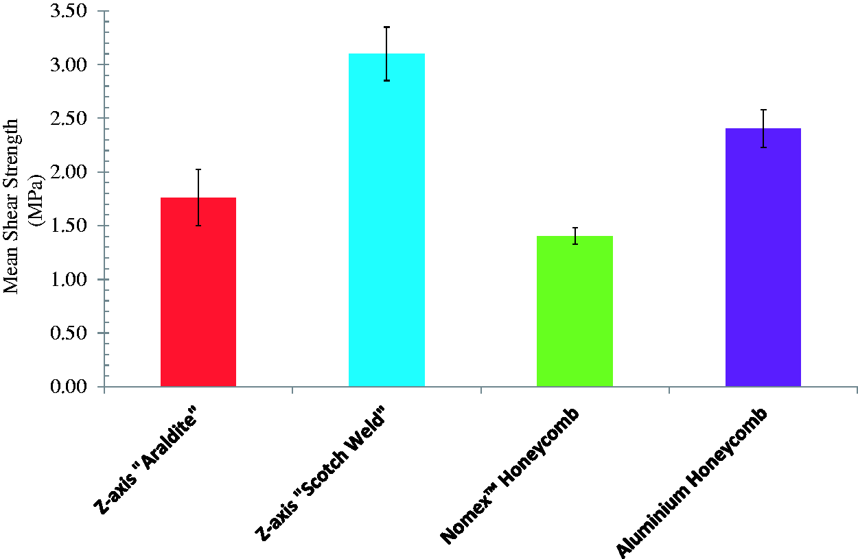
Comparison of the sandwich composite shear strengths with specified core materials.
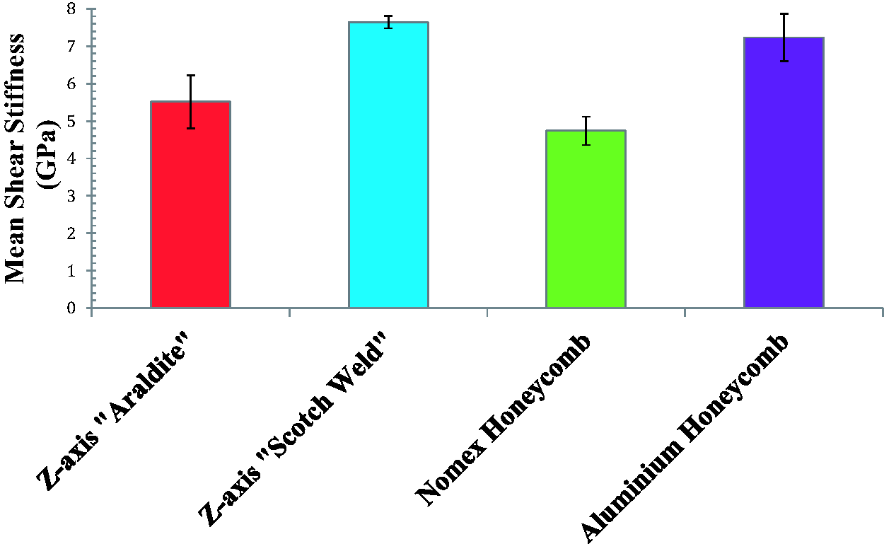
Comparison of the sandwich composite shear stiffnesses with specified core materials.
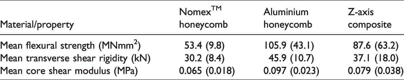
Summary of the mean flexural strength, transverse shear rigidity and core shear modulus for the Nomex® and aluminium honeycomb, and Z-axis composites.
General failure modes
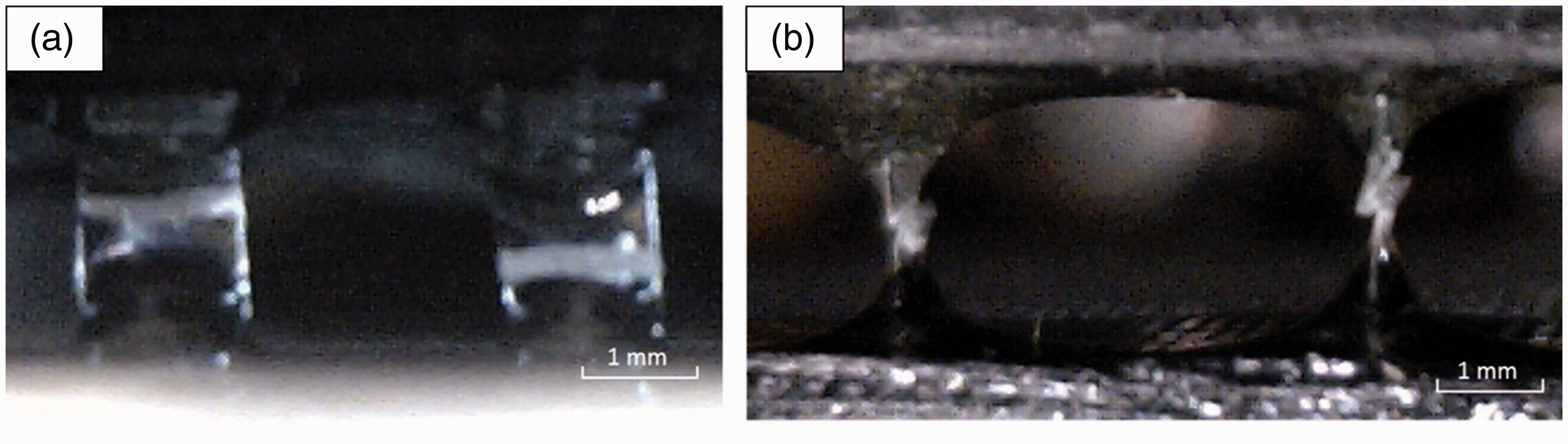
The dominant failure modes observed with the Z-axis composites when they were subjected to flatwise compression were Euler buckling and kink band-induced fracture of the vertically-aligned short-E-glass fibres. Figure 13(a) and (b) shows examples of E-glass fibre bundles in the Z-axis sandwich undergoing buckling and fracture via a kink band formation respectively. Figure 14 illustrates sequential micrographs that were recorded as a function of time during a flatwise compression test. The formation of an inclined kink band in the E-glass fibre bundle within the Z-axis composite is readily apparent. The aluminium and Nomex® honeycomb sandwich composites failed by buckling of the cell walls; the failure mode for a Nomex® sandwich sample during flatwise compression is shown in Figure 15. With reference to the flexural samples, in the case of the Nomex® sandwich composites, failure occurred through collapse of the honeycomb cell walls. The aluminium core sandwich panels however experienced cracking of the skin along with localised crushing of the core. The Z-axis samples failed abruptly through the de-bonding of the skin and core. Similar failure modes were reported in the literature [5,40]. For example, in composite sandwich panels where struts were present in some form (elongated Z-pins in X-cores, columns formed around stitches, or trusses) failure at the core-skin interface was observed commonly.
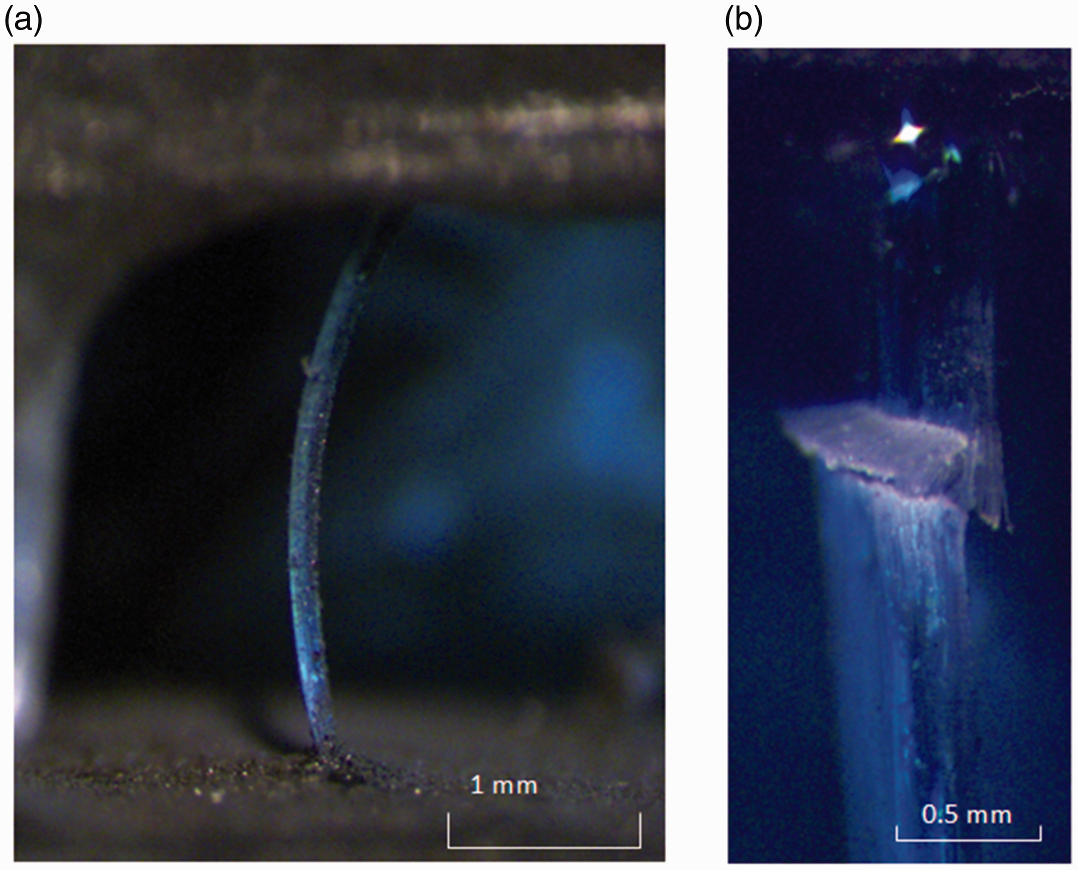
Micrograph of a 3 mm long E-glass fibre bundle composite undergoing: (a) buckling; and (b) fracture subsequent to the formation of a kink band.
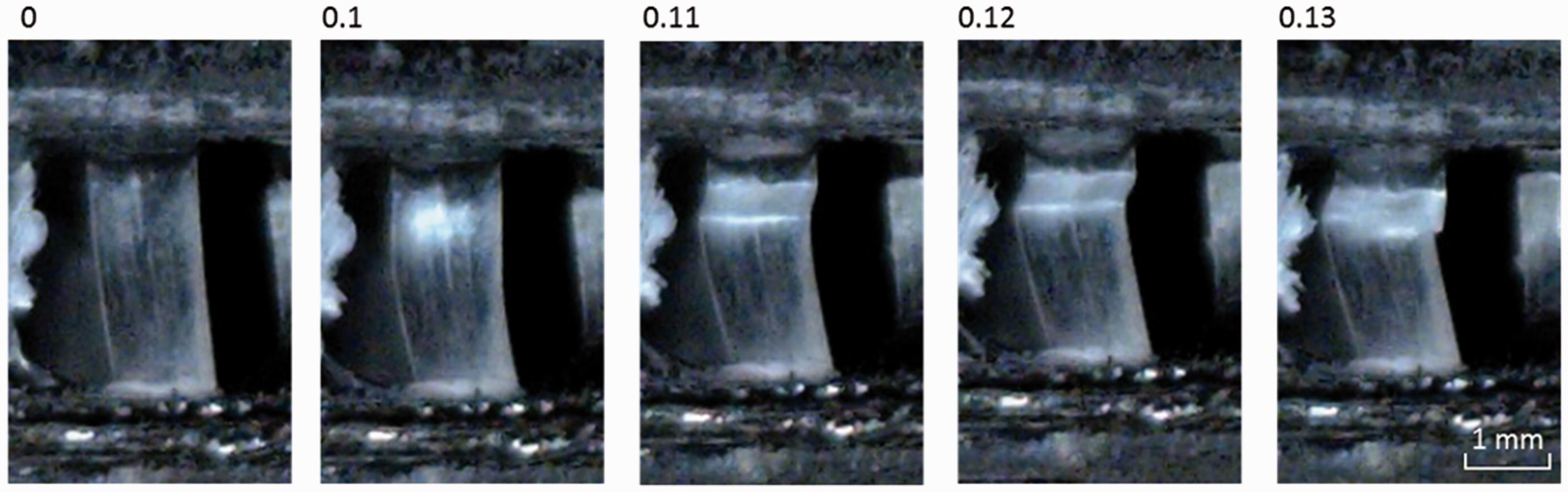
Real-time imaging of the formation of an inclined kink band in an E-glass fibre bundle within a Z-axis composite. All images represent the same fibre bundle but at different stages of the loading process. The values above each image refer to the compressive strain experienced by the sample at the time the image was taken.
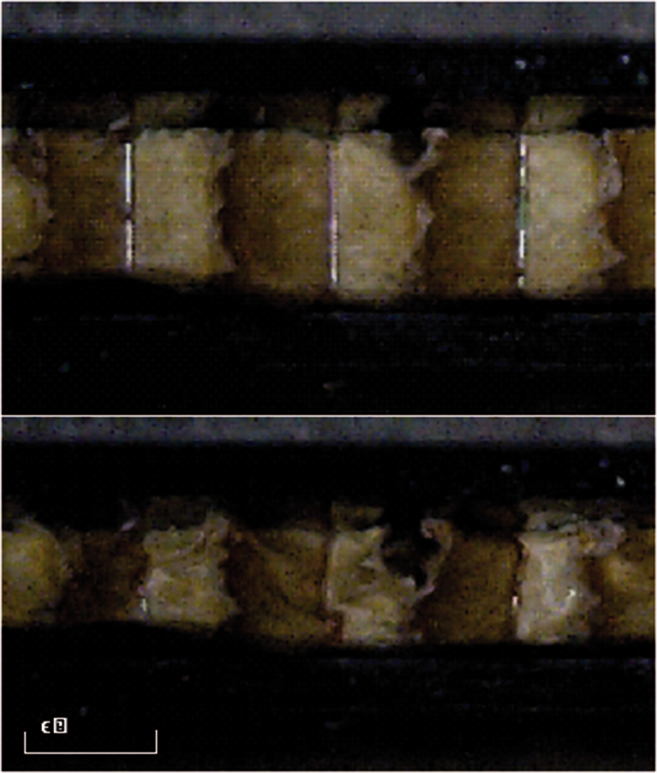
Side-view image of a Nomex® honeycomb sample (top) prior to and (bottom) following loading. Shear bands can be seen in the bottom image where the walls of the honeycomb have buckled.
Models on compressive loading of unidirectional and sandwich composites
A general review on the strength and stiffness of short-fibre, and sandwich composites can be found in references [41] and [42] respectively. Finite element modelling of Z-pinned fibres include the works of Grassi et al. [43] and Meo et al. [44]. It is proposed that the theories that are used to predict the properties of short-fibres [45] and Z-pinned composites [6,46,47] can be adapted and used with the current Z-axis composites. The micromechanics for the Z-axis composite is presented in Appendix-A.
Prospects for scaling up the production of Z-axis composites
When contemplating the scaling up of the Z-axis manufacturing process, a number of issues have to be considered including the following. Adhesive-backed cellulose paper: In the laboratory study, this method was chosen for convenience. The adhesive had the appropriate tack to secure the spatial orientation of the vertically-aligned short-fibre preforms. Moreover, it was sufficiently thin for the applied electric field to be not impaired significantly with regard to the grounded electrode. Other classes of non-conducting and flexible materials such as polymers and resin films can also be used. In contemplating a continuous production process involving a conveyor belt-based system, the adhesive-backed cellulose paper (similar in dimensions to that used in the prepreg or printing industries) can be fed and maintained in intimate contact to the grounded electrode. In some circumstance, the carbon fibre skin itself can be used as the grounded electrode and the short-fibres can be deposited directly on to it, secured and impregnated. Securing the spatial orientation of the vertically-aligned short-fibre preform: A number of adhesives can be used to achieve this objective. For example, photo-curing resins can be used because light can be coupled through the end-face of the E-glass fibres [48]. Resin films that are used conventionally to bond honeycombs to the skins can also be used. Moreover, the same resin system that is used to impregnate the vertically-aligned short-fibres can be sprayed on before the short-fibres are deposited. As the production process is intended to be continuous, localised heating, can be used to partially cross-link the adhesive. A number of resin suppliers offer hardener formulations to achieve specified rates of cross linking; this applies to the LY3505/XB3403 resin system used in the current study. Provided the cost and the desired properties for the Z-axis composites are not compromised, it was shown in Figure 11 that the resin system that is used to bond the vertically-aligned fibre can be deployed to optimise the mechanical properties. It is worth noting that the orientation of the short-fibres can be inclined at any desired angle after the fibres are deposited on the substrate and before the resin is partially cross-linked. In such a scenario and if the adhesive-backed substrate is flexible, the short-fibre arrays can be draped over complex shapes or used to produce horizontally-aligned short-fibre preforms and prepregs. Length of the short-fibres: In practice, applications will dictate the need for cores of different thicknesses. A similar procedure to that described here can be used to manufacture Z-axis composites using the current range of commercially available (up to 14 mm) “uniaxial” short-fibres. The issue with producing longer chopped fibres from conventional creels or bobbins is the intrinsic curvature in the continuous fibres. The radius of curvature will vary when traversing from the bore to the outer surface of the creel [39]. If longer uniaxial short-fibres are required, the production will have to be modified to eliminate the intrinsic curvature before the fibres are chopped. This can be achieved by extracting the fibres from the outer circumference or bore (if intermittent twists can be tolerated) using a pinch-roller payout system. The fibre bundles will have to be impregnated or wetted with a non-toxic low-boiling point solvent or the original binder solution and dried under tension; this will remove the original crimp and curvature present on the fibre. The fibres can be chopped using conventional methods. Another possible method to produce longer uniaxial short-fibres is to contemplate pultrusion where a large array of uniaxial short-fibres can be produced in the form of rectangular strips or circular rods. Another viable technique is to stack the core and this was proposed previously [21]. This approach will provide options for the development of unique hybrid cores. Controlling the fibre volume fraction in the core: In the current study, the grounded electrode with the cellulose paper and the vertically-aligned short-fibres were removed from the rig and weighed periodically to determine weight of the reinforcement. Obviously, this will not be practical in any continuous production method. Image analysis has been used previously to detect the fracture of individual filaments in a composite [48]. A similar approach can be adapted to detect the perimeter of the ends of the short-fibres as they are deposited on the grounded electrode. Alternatively, a calibration curve can be generated to quantify the deposition rate of the short-fibres as a function of time for a given set of operating and environmental conditions. A low-cost option would be to use an instrumented conveyor belt to determine the removal and/or deposition of the short-fibre. Controlling the location where the short-fibres are deposited: In cases where there is a need to distribute the short-fibres to predefined regions, this can be achieved by using a patterned grounded electrode or by having segmented grounded electrodes where each one is activated using a computer-controlled switching unit. Impregnating the vertically-aligned short fibre: This can be carried out in a number of ways. For example, the dip-coat method used in this study could be implemented. The excess resin can be removed by bringing it into contact with an absorbent material. However, this will contribute to the consumables cost and generate waste. One option is to spray the resin in a controlled manner to impregnate the short-fibres where the required quantity of the resin is delivered. Production cost: This aspect requires a detailed cost analysis but a rough comparison can be made with the conventional Nomex honeycomb. The cost of an equivalent short-E-glass fibres is £1.35/kg. The LY3505 resin and XB3403 hardener costs £9.15 and £14.87 per kg respectively. In the current study, in one set of controlled samples (where the weights of the core and resin used were quantified), 0.33 g of short-fibres and between 1.47 and 4.24 g of the resin system (mixed resin and hardener) were used to produce a preform of dimensions 50 x 50 mm. Assuming a weight of 2.85 g for the resin system (accounting for over-impregnation), scaling this up, 1 kg of the short-fibres can be used to produce approximately ten preforms of dimensions 1 m2. The current cost of purchasing Nomex® honeycomb with a 3.2 mm cell with a thickness of 3 mm is £27.30 for a dimension of 600 x 600 mm.
Other potential applications for the Z-axis composite
The Z-axis technology reported here can be adapted for a wide range of designs and applications. For example, the E-glass fibres can be replaced with carbon fibres in order to improve the specific properties further. E-glass can also be substituted with short-alumina and sapphire fibres for high-temperature application where the skins and resins are replaced with materials that can sustain significantly higher melting/degradation temperatures when compared with their organic counterparts. The vertically-aligned fibres do not necessarily have to be rods or rectangular plates, they can be composite coils and these can be used as cores in the form of springs. In the Z-axis composite design, the space between the vertically-aligned fibres can be used as cooling/heating channels with an appropriate fluid being permitted to flow through. There are realistic options for “smart” composites to be manufactured where for example, two or more short-fibre lengths can be used where the longer ones are used for bonding to the skins and the other for applications such as energy harvesting, vibration damping and damage detection. The prospect for optical data and image transmission/projection are realistic prospects as it is known that E-glass can transmit light [48]. Here, the skins and resins will have be chosen such that they are transparent to the wavelength of interest. It is anticipated that on the basis of the superior flat-wise compressive properties of the Z-axis composites, their impact properties can be engineered by selecting different or hybrid fibres and low-density matrices. Filling the spaces in between the short-fibres with an energy absorbing material such as Surlyn™ will be of interest as it will provide additional restraint to the vertically-aligned short-fibres and it is known to have self-healing characteristics [49].
Conclusions
The Z-axis composites exhibited out-of-plane compressive strengths that were over an order of magnitude higher than equivalent sandwich panels made with Nomex® and aluminium honeycomb cores [50]. The shear strength and stiffness of these Z-axis composites was also found to be superior to the honeycomb sandwich panels. Although the production of the Z-axis flexural specimens was not optimised, the flexural strength was higher than that of the Nomex® core sandwich composites but lower than that of the aluminium sandwich composite.
In situations where a high out-of-plane compressive strength is desired, it may be particularly advantageous to select a Z-axis composite over an alternative sandwich panel. The resistance to out-of-plane compression is provided without a significant reduction in the in-plane properties. It was found that the number of fibre bundles within the core of a Z-axis composite correlated positively with the out-of-plane compressive properties. This offers the opportunity to tailor the electrostatic manufacturing process to vary the final properties of the sandwich panel. For example, it allows control over the number of fibre bundles that are deposited to form the core. Furthermore, if a particular section of a sandwich panel requires increased out-of-plane compressive strength or stiffness, there is potential for the density of fibre bundles in that section to be increased accordingly.
Supplemental Material
sj-pdf-1-jsm-10.1177_1099636221993883 - Supplemental material for Vertically-aligned short E-glass fibre core sandwich composite: Production and evaluation
Supplemental material, sj-pdf-1-jsm-10.1177_1099636221993883 for Vertically-aligned short E-glass fibre core sandwich composite: Production and evaluation by Robbie White, Venkata R Machavaram, Benjamin A Fernando, Mark A Paget, Ashwini Prasad and Gerard F Fernando in Journal of Sandwich Structures and Materials
Footnotes
Acknowledgments
Robbie White (MSc) acknowledges funding from the Engineering and Physical Sciences Funding Council. Mark Paget and Gerard Fernando wish to thank Dr Garry Wells and the MoD/DSTL for MAST funding for the Z-axis demonstrator study. Ashwini Prasad will like to acknowledge funding from Innovate UK (Project AB135A). The authors are grateful to Professor Brian Ralph, Dr JDR Talbot, Frank Biddlestone, Carl Meggs and Jeremy Ahern for technical comments and assistance.
Declaration of Conflicting Interests
The author(s) declared no potential conflicts of interest with respect to the research, authorship, and/or publication of this article.
Funding
The author(s) disclosed receipt of the following financial support for the research, authorship, and/or publication of this article: This work was supported by Ministry of Defence (DSTL/MAST), Engineering and Physical Sciences Research Council (MSc Studentship (R White)), and Innovate UK (Project AB135A).
Supplemental Material
Supplemental material for this article is available online.
References
Supplementary Material
Please find the following supplemental material available below.
For Open Access articles published under a Creative Commons License, all supplemental material carries the same license as the article it is associated with.
For non-Open Access articles published, all supplemental material carries a non-exclusive license, and permission requests for re-use of supplemental material or any part of supplemental material shall be sent directly to the copyright owner as specified in the copyright notice associated with the article.