
Abstract
The effect of extreme cold temperatures on the quasi-static indentation and the low velocity impact behavior of woven carbon/epoxy composite sandwich panels with Nomex honeycomb core was investigated. Impact tests were performed at room temperature, –70°C, and –150°C. Two sizes of hemispherical impactor were used combined to three different impactor masses. All the impact tests were performed at the same initial impact velocity. The effect of temperature on the impact behavior is investigated by studying the load history, load-displacement curves and transmitted energy as a function of time curves. Impact damage induced at various temperatures was studied using different non-destructive and destructive techniques. Globally, more damages are induced with impact temperature decreasing. The results also show that the effect of temperature on the impact behavior is function of the impactor size.
Keywords
Introduction
Carbon fiber composite sandwich panels with Nomex honeycomb core are considered for the fabrication of lunar exploration rovers. Their thermal properties combined with their high strength and stiffness to weight ratio make them excellent candidates for space applications. On the moon, rovers will be exposed to an extremely harsh environment. Between the lunar day and night, the temperature can go from 120 °C to –150°C. In addition, in some permanent shadowed craters, temperatures can be even lower than −200°C [1]. In order for rovers to explore those shadowed areas, they will have to sustain extreme cold temperatures for extended periods of time. Composite materials are affected by temperature and temperature variations. Temperature variations from the stress-free curing temperature to the extreme cold lunar temperatures will lead to the development of internal stresses because of the high heterogeneity and anisotropy of composite structures. Composite materials properties are also going to be influenced by temperature changes.
Studies have shown that in-plane shear modulus and in-plane shear strength increase at low temperatures [2–4] as well as the interlaminar shear strength [5,6]. Kumagai et al. [2] studied the effect of low temperatures on the tensile behavior of carbon/epoxy woven laminates. They observed a decrease in tensile strength at low temperatures. Jean-St-Laurent et al. [4] investigated the effect of temperature on woven carbon/epoxy laminates under tension and compression loadings. They observed that while tensile strength decreases at cold temperatures, compressive strength increases. Other studies have looked into the effect of temperature on the interlaminar fracture toughness of composite materials [6–10]. Generally, in mode I, the interlaminar fracture toughness decreases with temperature for laminates made of unidirectional plies [6,8–10]. In mode II, a decrease in interlaminar fracture toughness at cold temperature was also observed by Shi et al. [6]. The effect of temperature on the core-facesheet delamination of sandwich structures has also received attention [11,12].
On the moon, rovers will operate on a rugged terrain with limited knowledge of the real nature of the ground due to the presence of a thick layer of loose lunar dust. Impacts between a rover and its surroundings are therefore possible. Moreover, those impacts are likely to occur at extreme cold temperatures. Composite laminates and composite sandwich panels are sensitive to out-of-plane loadings such as impacts. Impact behavior of composite structures is in fact problematic for most applications. Impact loadings can be caused by tool drops during handling and fabrication of composite structures, or by orbiting debris in space structures. They can also occur during takeoff or landing of aircraft, etc. Impact damages, even barely visible ones, are known to induce important strength reduction for composite structures [13]. Therefore, there has been a large number of studies on the impact behavior of composite laminates and sandwich panels [13–16]. For composite sandwich panels, studies have shown that core density and core thickness [17–20], composite skin thickness [17,19–21], composite skin constituents [18,20], and impact energy [17–21], amongst other parameters, have a significant effect on the behavior under impact loading and the damage induced. The size of the impactor also has an influence on the behavior of composite sandwich panels under impact loading [20,22].
Amongst the studies on the impact behavior of composite structures, only a few have looked into the effect of temperature. Composite laminates of glass [23–28] or carbon [29–40] fibers combined with thermoset resin are the types of composite structures that have received the most attention regarding that subject. However, other studies have also looked at the effect of temperature on the impact behavior of other types of laminates, such as natural fiber composite laminates [41] or composite laminates with thermoplastic resin [33,36,42,43].
Amongst the works on the impact behavior of carbon/epoxy laminates at cold temperatures a few investigated temperatures as low as −150°C [31,34,39]. Gómez-del Río et al. [39] studied the effect of low temperatures on the low-velocity impact behavior of carbon/epoxy laminates from room temperature to −150°C. They noted that decreasing temperature has a similar effect as increasing impact energy. They observed more severe damages and a deeper residual indentation depth at cold temperatures, while the absorbed energy was not affected. It means that although there are more damages at cold temperature, less energy is required to produce them. Their results also show that the stacking sequence and the fiber reinforcement architecture have an influence on the effect of temperature on the impact behavior. López-Puente et al. [34] studied the effect of low temperatures on the intermediate to high velocity impact behavior of carbon epoxy laminates over the same range of temperatures. They showed that cold temperature affects negatively the behavior of laminates under a certain velocity. Passed that velocity, temperature has no effect on the impact behavior. Sánchez-Sáez et al. [31] studied the dynamic and quasi-static flexural behavior of carbon/epoxy laminates at room temperature, –60°C, and −150°C. They observed a greater number of delaminations at cold temperatures. They also showed that the absorbed energy and the maximum strength decrease at cold temperatures.
The effect of temperature on the impact behavior of sandwich structures has received limited attention [44–48] compared to composite laminates. Salehi-Khojin et al. [46] studied the behavior of carbon/Kevlar sandwich panels with Kraft paper honeycomb core filled with polyurethane foam subjected to impact loadings from −50°C to 120 °C. They observed more damage and fiber breakage at −50°C. Opposite results were obtained by Yang et al. [45] for carbon/epoxy sandwich panels with foam core impacted at temperature ranging from −45.6 °C to 82.2 °C. They observed larger damaged areas for specimens impacted at 82.2 °C. However, they explained their results by the reduction of the foam core modulus at high temperature. Finally, Elamin et al. [48] studied the behavior of woven carbon/epoxy sandwich panels with PVC foam core under impact loading from −70°C to room temperature. They observed an increase in damage at cold temperatures and that the load required to break the top facesheet diminishes at cold temperatures. They also noted that the maximum impactor displacement is larger at cold temperatures. There is, to the best knowledge of the authors, no study on the impact behavior of sandwich panels at temperatures sufficiently low, such as −150°C, to be representative of space applications. Moreover, most of the sandwich panels studied are not made of materials that could be considered for space applications, due to the stringent requirements in outgassing and compatibility of coefficients of thermal expansion.
The aim of this project is to study the effect of extreme low temperatures on the low velocity impact behavior of woven carbon/epoxy sandwich panels with Nomex honeycomb core for lunar exploration rovers. Quasi-static indentation tests and impact tests were performed at room temperature, −70°C, and −150°C. Two sizes of indentor/impactor were used for both quasi-static indentation tests and impact tests. For the impact tests, three different masses were used. The effect of temperature on the behavior during impact is evaluated by studying the load history, the load-displacement curves of the impactor, and the transmitted energy during impact. Visual inspections, residual depth of indentation evaluations, ultrasonic C-scan inspections, and cross section observations of the impacted specimens were performed to evaluate the effect of temperature during impact on the induced damages.
Material and specimen geometry
The sandwich panel studied is made of two composite skins and a Nomex honeycomb core. The sandwich panel has the following stacking sequence: [(±45)/(0/90)/(0/90)/(±45)/core(L)/(±45)/(0/90)/(0/90)/(±45)]. The composite skins are each made with four plies of carbon/epoxy plain weave fabric. The resin is a 977–2 toughened epoxy. This particular resin epoxy has already been used in studies of composite materials for cryogenic applications [8,12,49]. The plain weave fabric is made with T300D 3 K carbon fibers. The composite skins were cured then bonded to the core with 3 M AF 191 K epoxy film adhesive. The skins are approximately 0.9 mm thick each. The composite and the adhesive were cured at 179 °C. The core is a Nomex honeycomb core with regular hexagonal cells of 4.76 mm. The core has a thickness of 12.7 mm and has a density of 48 kg/m3. The core ribbon direction (L) is aligned with the 0° fibers of the (0/90) plies (Figure 1). All of the components of the sandwich panels were chosen because they fulfilled space application requirements. The properties of the composite skins were characterized at room temperature, −70°C, −130°C, and/or −150°C [4].
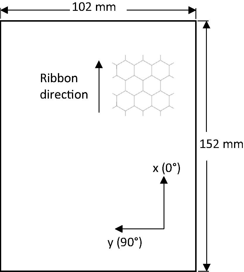
Sandwich panel specimen with dimensions and orientations.
Sandwich panels were cut with a diamond saw cooled with water. The specimen final dimensions are 102 mm×152 mm (Figure 1). These dimensions were chosen in order to perform compression after impact tests [50]. The panels are approximately 14.5 mm thick. Specimens were cut from three separate larger panels. For each test condition, specimens cut from different panels were used.
Quasi-static indentation
Experimental set-up
Quasi-static indentation tests were performed on a universal testing machine MTS 100 Insight SL. Two hemispherical indentors were used with diameters of 12.7 mm and 25.4 mm. Specimens were simply resting on an annular steel support with an inner diameter of 76.2 mm and an outer diameter of 110 mm. The indentor sizes and the fixture used are common for impact testing of composite structures and are therefore used for the quasi-static indentation and impact tests. For impact testing, specimens were clamped, while they were simply resting on their support for the quasi-static indentation tests. For the quasi-static indentation tests, clamping was not possible due to space limitation inside the thermal chamber at cold temperatures. For the quasi-static indentation tests, the support was placed directly on the frame of the universal testing machine. The same steel support was used for the quasi-static indentation and impact tests.
For the tests at cold temperatures, the testing fixture was placed in a thermal chamber. The chamber was cooled with liquid nitrogen. The load cell was placed outside of the chamber. However, to ensure that the temperature of the fixture inside the chamber connected to the load cell did not influence the load measurements, a heating ring was installed on the connecting rod between the load cell and the fixture (Figure 2). Two additional thermocouples were placed inside the chamber.
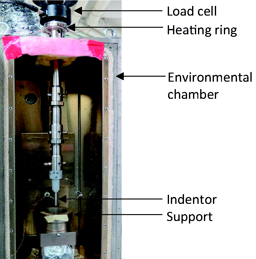
Quasi-static indentation experimental set-up.
Methodology
Quasi-static indentation tests were performed at room temperature, −70°C, and −150°C. Tests were performed at a speed of 1.25 mm/min.
Two preliminary tests were performed at room temperature, one with each indentor, in order to determine the maximum applied displacement for the subsequent tests. The maximum displacement was chosen in order to induce a significant amount of damage, while the top skin still retains load bearing capacity. For the 12.7 mm-diameter indentor, a depth of 5 mm was chosen, while for the 25.4 mm-diameter indentor a depth of 6 mm was chosen. For room temperature tests, two specimens per indentor were tested in addition to the one for the preliminary test. At cold temperatures, three tests per indentor were performed. All tests subsequent to the preliminary tests included complete unloading.
The displacement of the indentor was measured using two different techniques. The crosshead displacement of the tensile machine was used. The displacement of the indentor was also measured with a 3 D digital image correlation system. In order to do so, a speckle pattern was directly applied on the indentor. The values obtained from the crosshead displacement were validated with the 3 D digital image correlation system measurements. Displacement measurements between the two techniques were the same at room temperature, −70°C, and −150°C. In order to simplify the tests, the crosshead displacement was therefore used. Loads were measured with a 10 kN load cell.
During the tests, two thermocouples were used to measure the temperature. One was placed over the specimen top surface, while the other was placed near the specimen bottom surface. Upon testing, the temperature over the specimen top surface had reached the testing temperature, while the temperature near the bottom surface was higher. At −70°C, a 5 °C difference was measured, while at −150°C an 11 °C difference was measured. One explanation for those differences is the thermal bridge between the part of the steel fixture inside the chamber and the one outside the chamber. After cooling, tests started when the temperature difference between the two thermocouples reached a constant value.
A 3 D digital image correlation system was used to measure the residual depth of indentation of the top facesheet of the damaged specimens.
Results
Load-displacement curves
Figures 3 and 4 present the load-displacement curves obtained respectively with the 12.7 mm and 25.4 mm-diameter indentors at room temperature, −70°C, and −150°C. The curves were chosen to be the most representative of the overall results for each test condition. It is at −150°C, for both indentors, that the variation between the curves is the largest.
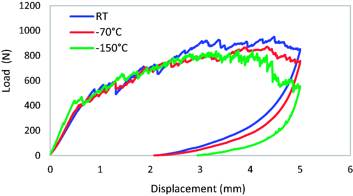
Load-displacement curves for the 12.7 mm-diameter indentor at room temperature, −70°C, and −150°C.
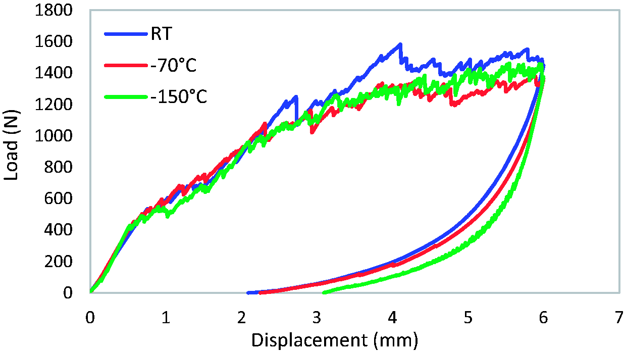
Load-displacement curves for the 25.4 mm-diameter indentor at room temperature, –70°C, and –150°C.
The curves show that the load reaches higher values at room temperature than at −70°C and −150°C fort both indentor sizes.
For the 12.7 mm indentor (Figure 3), at −150°C, the load starts to decrease significantly before the displacement reaches its maximum value of 5 mm. It indicates that damage is important enough to affect locally the load bearing capacity of the skin under indentation. This was observed for two specimens out of three. The panel behavior, before the initiation of damage, is more rigid with temperature decreasing. Finally, after unloading, the final displacement, which corresponds to the displacement when the load reaches a value of zero, is larger at −150°C. This is an indication of a larger residual depth of indentation.
For the 25.4 mm indentor (Figure 4), the curves are very similar for the tests at −150°C and −70°C. However, the final displacement, after unloading, is larger for specimens tested at −150°C, an indication of a larger residual depth of indentation for this indentor as well.
Residual depth of indentation
Figure 5 presents the residual depth of indentation of specimens tested at room temperature, −70°C, and −150°C. The residual depth of indentation is presented for the same specimens as the ones used for the curves in Figures 3 and 4. The maximum residual depth of indentation value is almost the same at room temperature and −70°C for both indentors. However, at −150°C, the maximum residual depth of indentation value is significantly larger in both cases.
Residual depth of indentation for specimens tested with a) the 12.7 mm and b) the 25.4 mm indentors at room temperature, –70°C, and –150°C.
Impact
Impact conditions, experimental set-up and methodology
All the impact tests were performed on a drop tower Instron 9340. In order to study a wide range of damage types and sizes, different impact conditions were studied. However, since lunar exploration rovers are limited to a very small velocity, all the tests were performed at the same initial impact velocity of 1 m/s. Two sizes of hemispherical impactor were used in order to induce a wide range of damage sizes: one with a diameter of 12.7 mm and one with a diameter of 25.4 mm. The impactor with a 12.7 mm-diameter was combined with two masses of 5 kg and 10 kg, while the 25.4 mm-diameter impactor was combined with three masses of 5 kg, 10 kg, and 20 kg. The three masses correspond respectively to an impact energy of 2.5 J, 5 J and 10 J. The 20 kg mass was not used for the 12.7 mm-diameter impactor, since damages induced by the 10 kg mass were already very extensive. The chosen impact conditions induced damage from barely visible impact damage to an almost complete panel perforation. For each impact condition at each temperature, five specimens were tested.
The drop tower is equipped with an environmental chamber. The chamber is originally designed to cool down to a minimum temperature of −50°C using liquid nitrogen. Minor modifications were made to the system in order to cool down to −150°C. The valve that controlled the interring of liquid nitrogen and the chamber fan were controlled by an outside system instead of using the drop tower control system. Two thermocouples were installed inside the chamber. One was placed just above the specimen, and the other was placed under the specimen. The thermocouple placed above the specimen was used for control. Finally, insulation was added.
During impact, specimens were clamped on the same steel fixture as the one used for the quasi-static indentation tests using a built-in pneumatic system. An anti-rebound system was used to prevent a second impact on the specimens.
Instrumented impactors were used to record the load. From the load data, the impactor velocity and displacement and the energy transferred to the specimen are calculated using expressions from the ASTM Standard D7136 [51]. An initial impact velocity of 1 m/s was assumed for the calculation. A high-speed camera was used to validate the impactor velocity.
Prior to testing, specimens were dried in an oven to remove moisture. For the cold temperature tests, once the temperature of both thermocouples reached the required temperature, the temperature was kept constant for 15 minutes, then the test was performed. A small shelf was installed inside the chamber in order to condition specimens prior to testing.
Load-time and load displacement curves
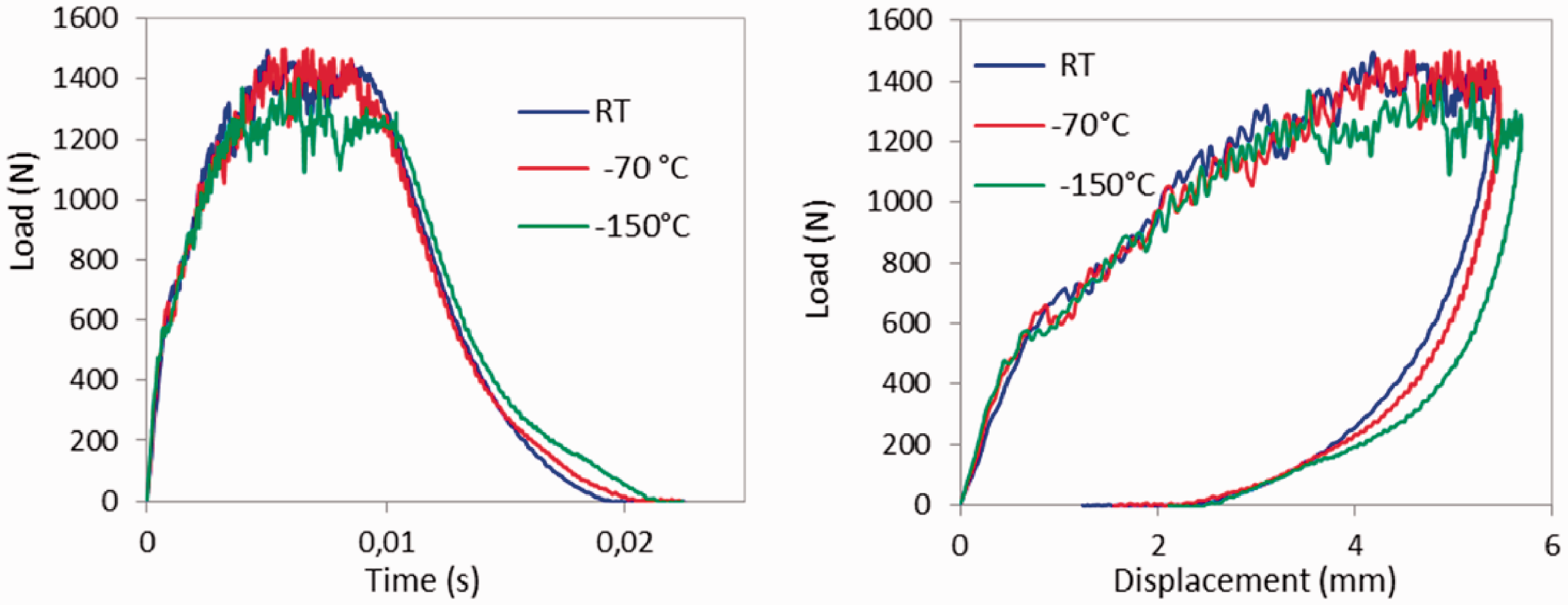
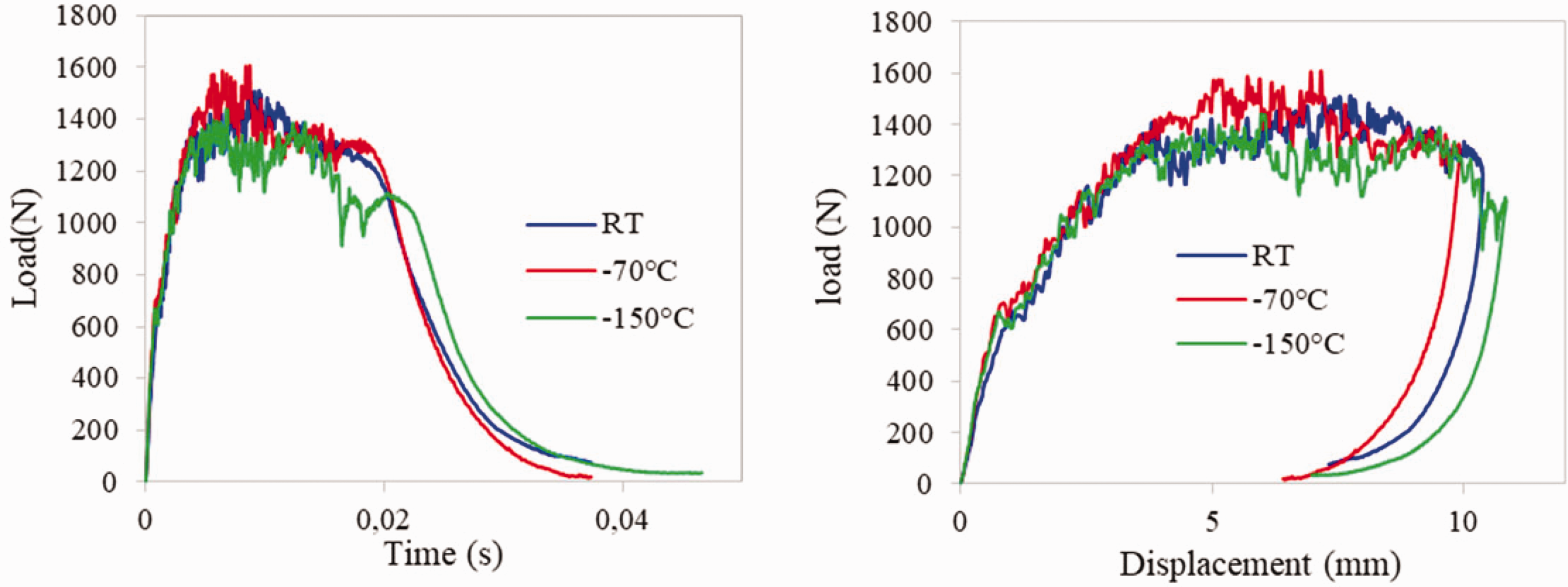
Figures 6 and 7 present the load history and load-displacement curves for the 12.7 mm impactor with the 5 kg and 10 kg masses respectively. The curves presented are representative of the results obtained for all the specimens at each temperature and for each impact condition. For this impactor, the effect of temperature is clearly visible for both impact conditions. Loads decrease between room temperature and −150°C. At −150°C, for specimens impacted with the 5 kg mass, the load history is characterized by important load drops. Those load drops are present in most of the specimens impacted at −150°C. They are an indication of important damage development in those specimens. The maximum displacement of the impactor increases at −150°C. For specimens impacted with the 12.7 mm impactor combined with the 10 kg mass (Figure 7), there is a second bell on the load history curves at −70°C and −150°C. This second bell is an indication that the impactor has reached and impacted the bottom skin of the sandwich specimen. At −70°C, the second bell is smooth for almost all the specimens. It means that although there is an impact between the impactor and the bottom skin, there is nearly no damage induced by that second impact. At −150°C, the second bell on the load history curve is characterized by multiple small load drops, an indication of damage initiation and propagation in the bottom skin.
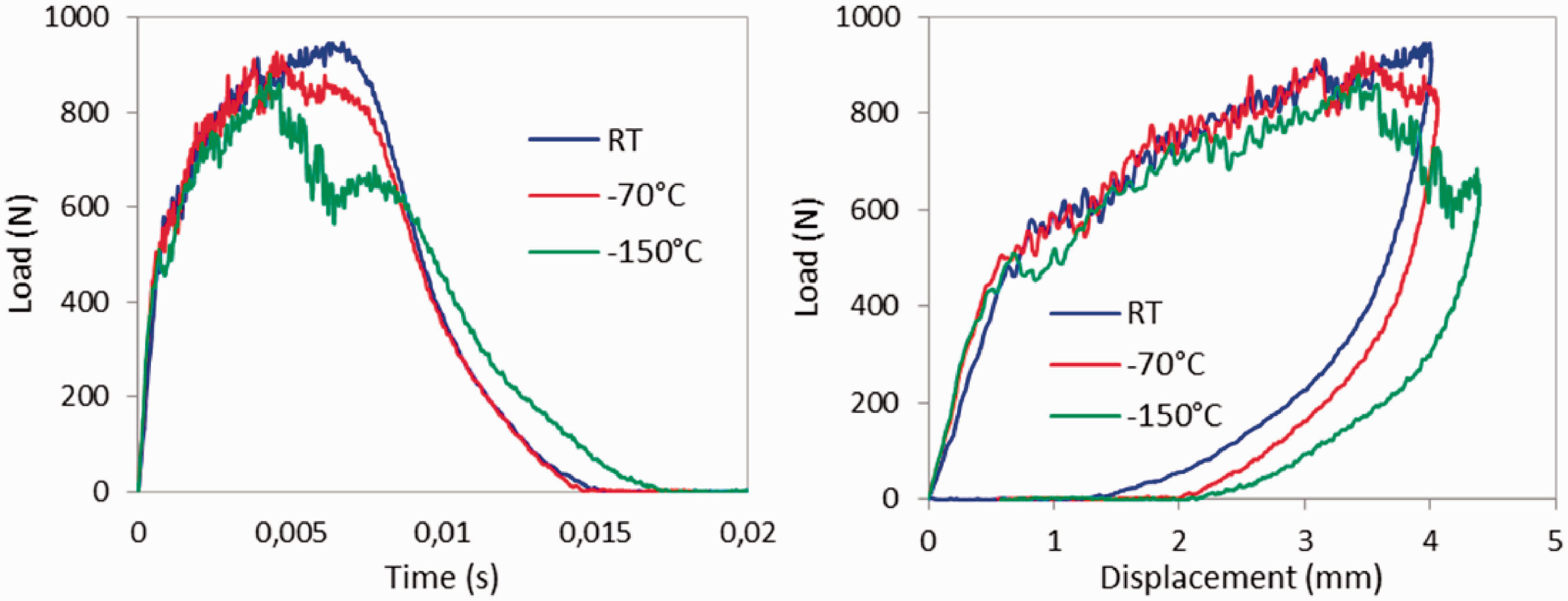
Load-time and load-displacement curves for the 12.7 mm impactor with the 5 kg mass at room temperature, –70°C, and –150°C.
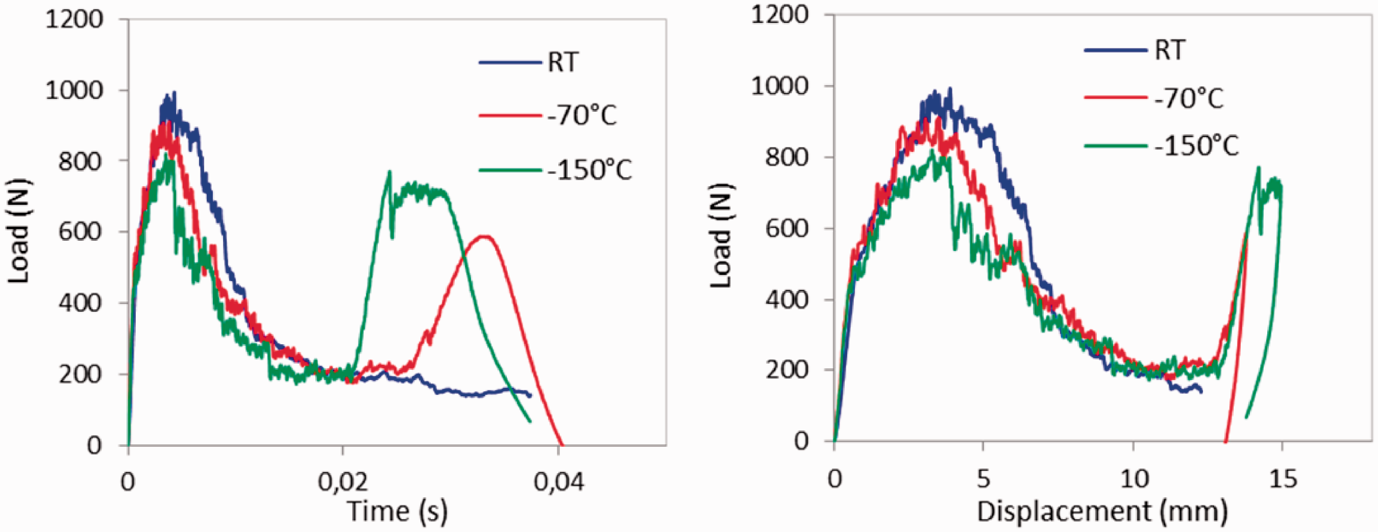
Load-time and load-displacement curves for the 12.7 mm impactor with the 10 kg mass at room temperature, –70°C, and –150°C.
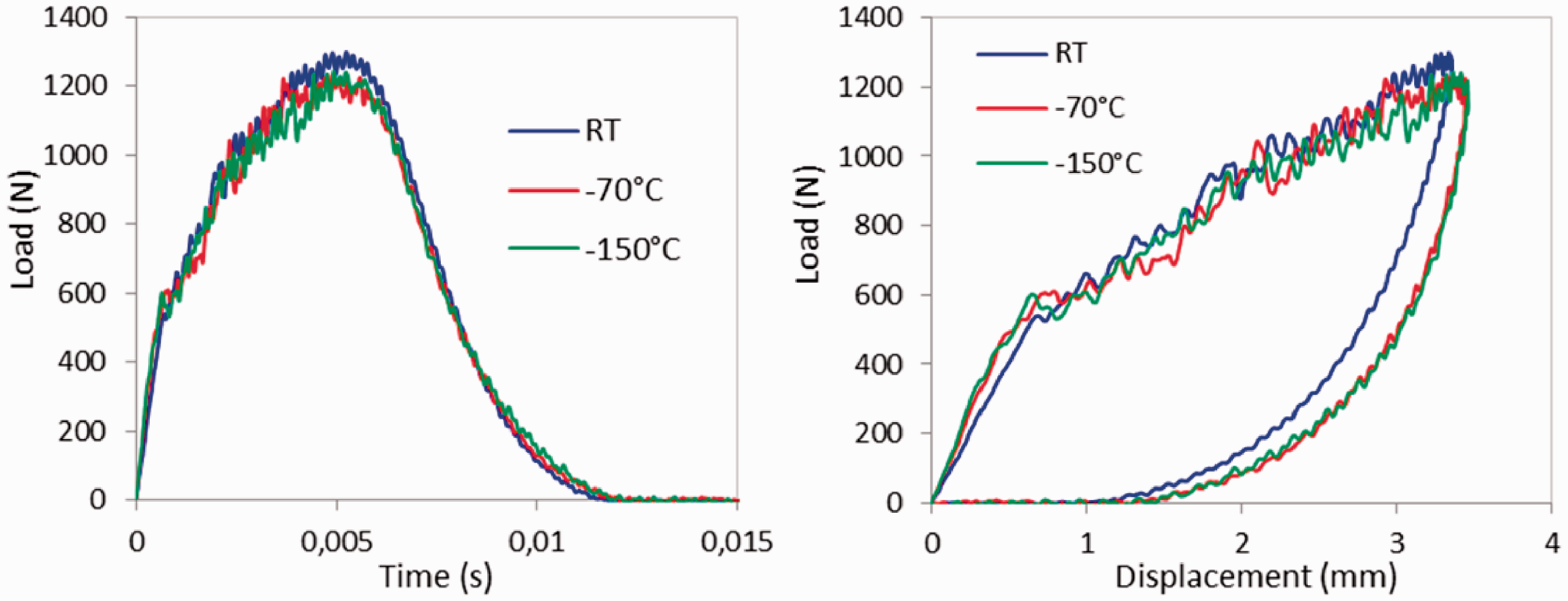
Figures 8 to 10 present the load history and load-displacement curves for the 25.4 mm impactor with the 5 kg, 10 kg, and 20 kg masses respectively. The curves presented are representative of the results obtained for all the specimens at each temperature and for each impact condition and the following observations are made for all the specimens. Generally, loads are slightly smaller at −150°C than at room temperature. The maximum impactor displacement also increases from room temperature to −150°C. The effects of temperature are less pronounced for this impactor when looking at the load history and the load-displacement curves. In fact, they are almost negligible with respect to variations from one specimen to another.
Load-time and load-displacement curves for the 25.4 mm impactor with the 5 kg mass at room temperature, –70°C, and –150°C.
Load-time and load-displacement curves for the 25.4 mm impactor with the 10 kg mass at room temperature, –70°C, and –150°C.
Load-time and load-displacement curves for the 25.4 mm impactor with the 20 kg mass at room temperature, –70°C, and –150°C.
For both impactors, a closer look at the load-displacement curves shows that the panel behavior is stiffer as temperature decreases from room temperature to −150°C. Because of that, the damage initiation occurs for smaller displacement of the impactor at cold temperatures.
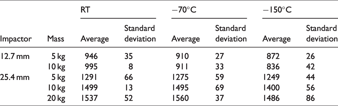
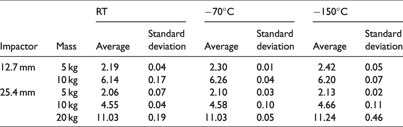
Tables 1 and 2 present respectively the average maximum load and average maximum displacement for each impact condition at each temperature when available.
Average maximum load in N.
Average maximum displacement in mm.
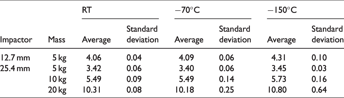
For specimens impacted with the 12.7 mm impactor, there is a decrease in the average maximum load from room temperature to −150°C. For this impactor, the highest standard deviation is obtained at −150°C with the 10 kg mass. An increase in maximum displacement at −150°C is measured for specimens impacted with the 5 kg mass.
For the 25.4 mm impactor, there is also a decrease in average maximum load at −150°C. However, the standard deviation is too high to conclude with certainty on the effect of temperature on that parameter. A similar conclusion applies to the increase in average maximum displacement at −150°C for the 25.4 mm impactor for all three masses.
Transmitted and absorbed energy
Typical transmitted energy as a function of time is presented in Figure 11. The absorbed energy used to damage a specimen corresponds to the end plateau value.
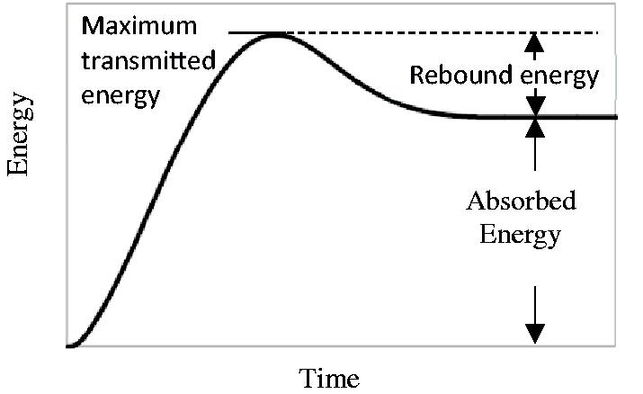
Typical energy as a function of time curve for impact loadings.
The calculation of the transmitted energy (E) is based on the expression from the ASTM standard D7136 [51]: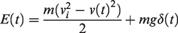
Figure 12 presents the evolution of transmitted energy as a function of time for specimens impacted with the 12.7 mm impactor. The curves presented are representative of the overall results and the following observations apply to all the specimens tested. For specimens impacted with the 5 kg mass (Figure 12(a)), the impactor rebounded and was caught by the anti-rebound system. The absorbed energy increases with temperature decreasing. For the 10 kg mass (Figure 12(b)), the impactor did not rebound. At −70°C and −150°C, the impact on the bottom skin can be seen by the second bump on the energy as a function of time curves. For this impact condition, the absorbed energy is almost the same at all three temperatures since the energy, in all cases, was fully transmitted to the specimens. However, as temperature decreases, the transmitted energy before the second impact diminishes. It means that the amount of energy required to perforate the top skin decreases at cold temperatures, leaving energy in the impactor to reach and damage the bottom skin.
Transmitted energy as a function of time for specimens impacted with the 12.7 mm impactor combined with the a) 5 kg and b) 10 kg masses at room temperature, –70°C, and –150°C.
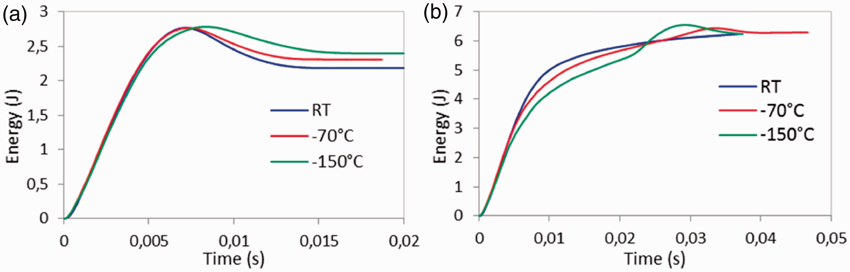
Figure 13 presents the evolution of transmitted energy as a function of time for specimens impacted with the 25.4 mm impactor using the 5 kg, 10 kg, and 20 kg masses. For the 5 and 10 kg masses (Figure 13(a) and (b)), the impactor rebounded and was caught by the anti-rebound system. For the 20 kg mass (Figure 13(c)), no rebound was observed although the absorbed energy is lower than the maximum transmitted energy. It means that the impactor moved back up a little after reaching the absolute maximum displacement. For all the impact conditions, the effect of temperature on the absorbed energy is almost negligible.
Transmitted energy as a function of time for specimens impacted with the 25.4 mm impactor combined with the a) 5 kg, b) 10 kg, and c) 20 kg masses at room temperature, −70°C, and −150°C.
The average absorbed energy for all the impact conditions is presented in Table 3. For specimens impacted with the 12.7 mm impactor and the 5 kg mass, the absorbed energy increases at cold temperatures, an indication that there is more severe damage induced at cold temperatures. This will be assessed by the damage evaluation. From room temperature to −150°C, the increase in the average absorbed energy is 11%. For all the other impact conditions, the absorbed energy is not affected by temperature changes.
Absorbed energy (J).
Impact damage characterization
Visual inspection
A visual inspection of all the specimens was performed. Figure 14 shows damaged specimens impacted with the 12.7 mm-diameter impactor (5 kg and 10 kg masses) and the 25.4 mm-diameter impactor (10 kg and 20 kg masses) at room temperature, −70°C, and −150°C. The specimens presented are representative of the overall results and the following observations are made for all of the specimens. For those impact conditions, there are generally more visible cracks on the upper skin with decreasing temperature except for the 12.7 mm impactor combined with the 10 kg mass. For that impact condition, the top facesheet is completely perforated at all temperatures. The nature of the visible cracks is probably a combination of damage accumulation. For specimens impacted with the 25.4 mm impactor and the 20 kg mass, at room temperature, there are large cracks aligned with the ± 45°- directions on the perimeter of the damaged area for most of the specimens. At −70°C, there are also large cracks aligned with the ± 45°- directions on the damaged specimens but in a smaller quantity. The damaged area starts to take the form of the impactor. At −150°C, the shape of the damaged area is rather circular, meaning that the impactor perforates the skin more easily at cold temperatures. Specimens impacted with the 25.4 mm-diameter impactor and the 5 kg mass are not included in Figure 14. For those specimens, damages are barely visible at all three temperatures, making it impossible to conclude anything from the visual inspection.
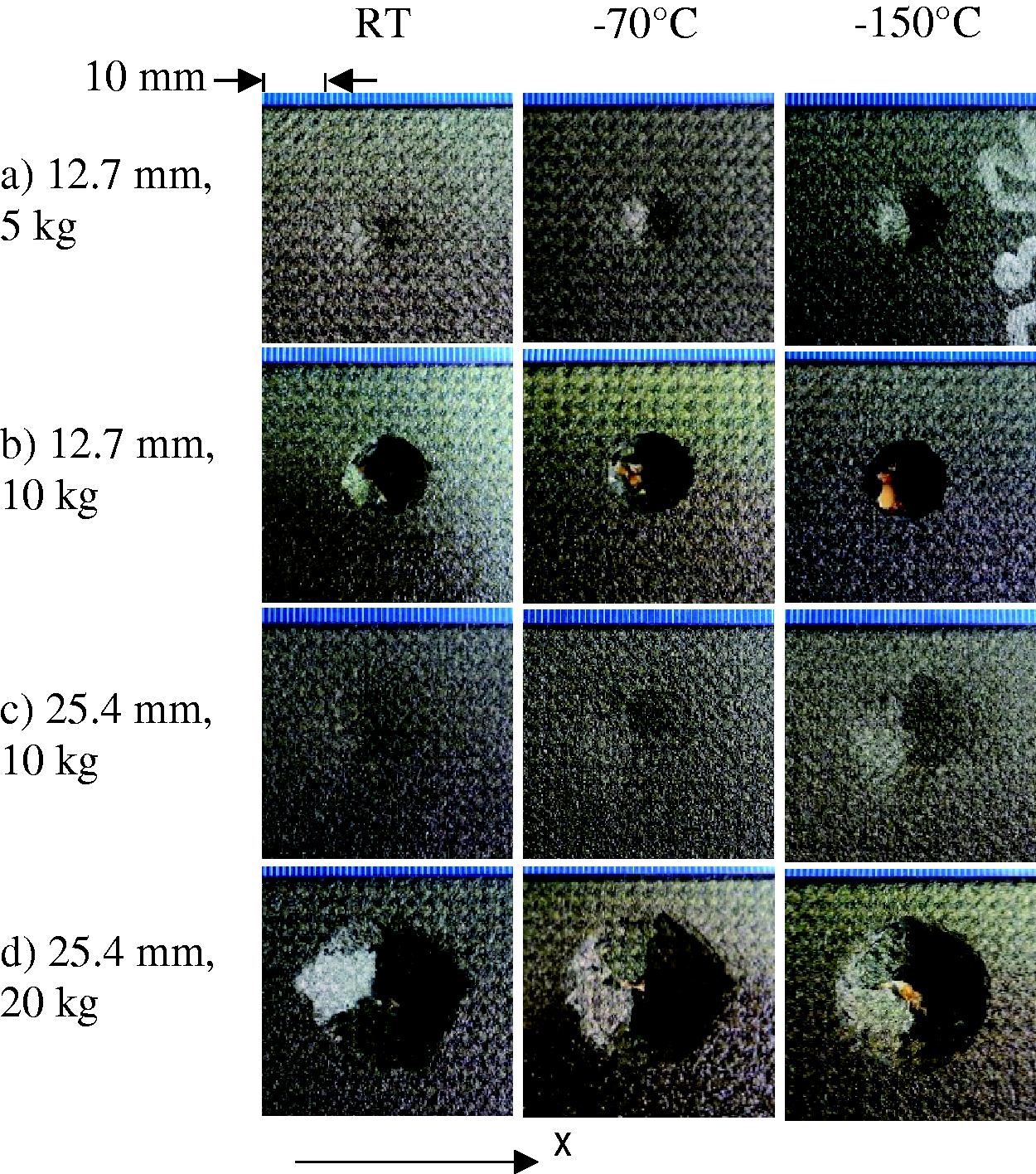
Top facesheet of specimens impacted at room temperature, −70°C, and −150°C.
For all the specimens impacted with the 12.7 mm-diameter impactor and the 10 kg mass, at −150°C, the impact loading also induces damages on the bottom skin. They are barely visible, but can be detected by a light touch. The presence of those damages was revealed by the load history curves. Damages on the bottom skin were also detected for one out of five specimens impacted at −70°C. Figure 15 presents the out-of-plane displacement of the bottom facesheet of a specimen impacted at −150°C obtained with a 3 D digital image correlation system.
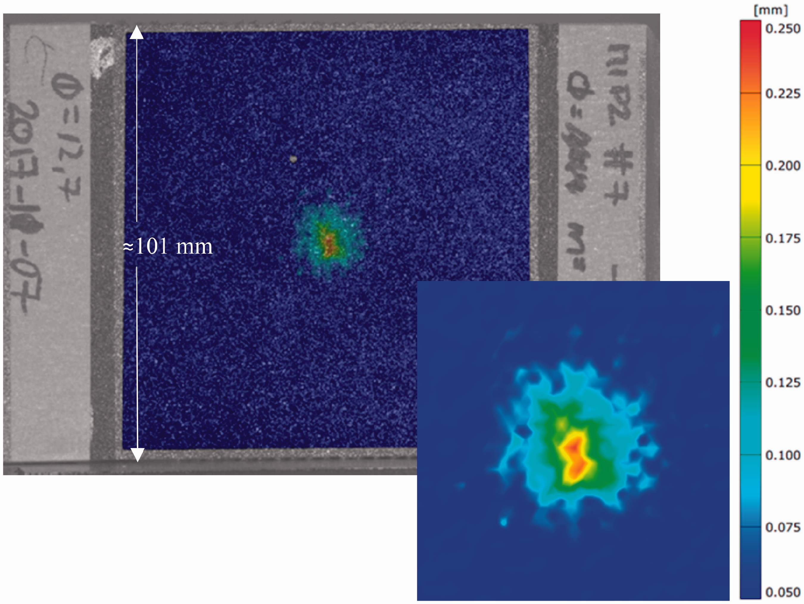
Out-of-plane displacement of the bottom facesheet of a specimen impacted at –150°C with the 12.7 mm-diameter impactor and the 10 kg mass.
Depth and size of the damaged area
The damaged surface of the specimens was analyzed with a 3 D digital image correlation system for all the impact conditions, except for specimens impacted with the 12.7 mm impactor and the 10 kg mass. For those specimens, the top skin was completely perforated. It was therefore not possible to measure the residual depth of indentation.
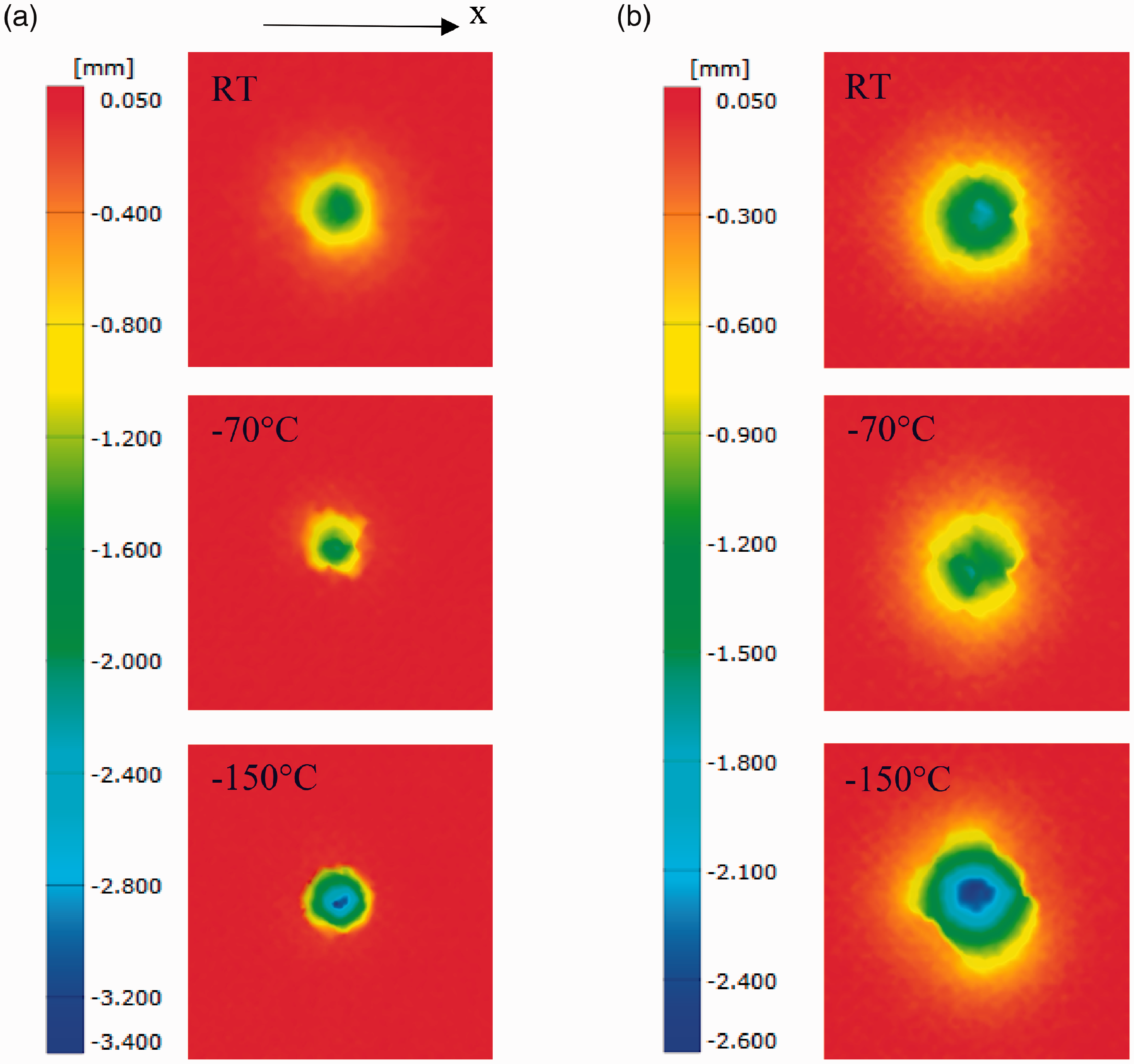
The depth of indentation was evaluated on a section along the x- direction passing through the center of the damaged area for each specimen. Figures 16 and 17 present the depth of indentation along the x- direction at all temperatures for specimens impacted with the 12.7 mm-diameter impactor and the 5 kg mass and with the 25.4-mm diameter impactor and the 5 kg, 10 kg, and 20 kg masses. The curves presented are chosen to be representative of the average results obtained.
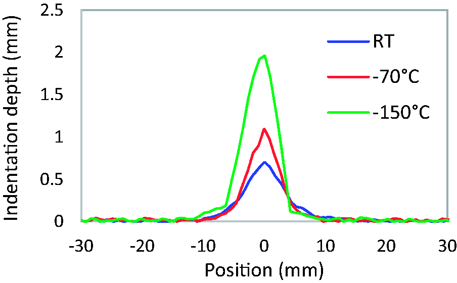
Residual indention depth along the x- direction for specimens impacted with the 12.7 mm impactor and the 5 kg mass at room temperature, −70°C, and −150°C.
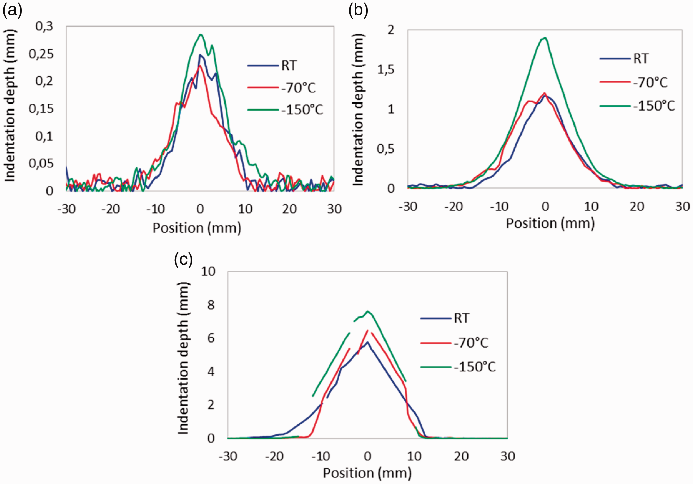
Residual indention depth along the x- direction for specimens impacted with the 25.4 mm impactor and the a) 5 kg, b) 10 kg, and c) 20 kg masses at room temperature, −70°C, and −150°C.
For specimens impacted with the 12.7 mm impactor and the 5 kg mass (Figure 16), the residual depth of indentation increases from room temperature to −150°C. Along the x- direction, the size of the damaged area is similar at all temperatures.
For specimens impacted with the 25.4 mm impactor (Figure 17), the residual depth of indentation is similar at room temperature and −70°C and then increases at −150°C. For the 5 kg and 10 kg masses (Figure 17(a) and (b)), the size of the damaged area along the x- direction is similar at all temperatures. For the 20 kg mass (Figure 17(c)), at cold temperatures, damage is more localized. At room temperature, impact produces large cracks on the perimeter of the damaged area in a diamond shape, while at cold temperatures the damaged area takes the shape of the impactor because of the perforation of the skin which explains the smaller damaged area.
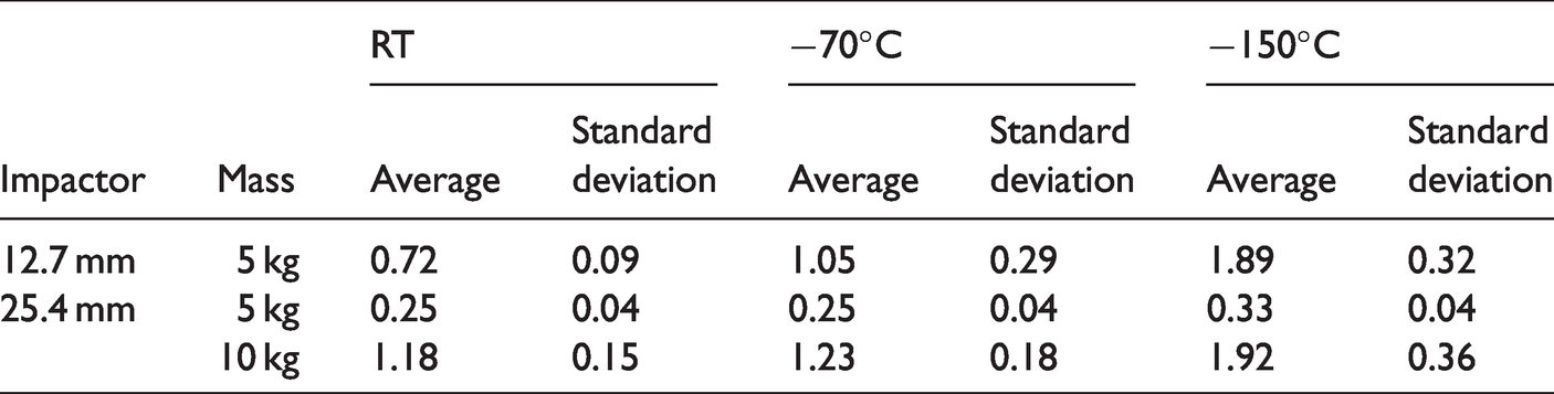
The maximum residual depth of indentation value was evaluated for all the specimens. The average value for each impact condition is presented in Table 4, except for specimens impacted with the 12.7 mm impactor and the 10 kg mass and the 25.4 mm impactor and the 20 kg mass. For those specimens, damages are too extensive to properly reproduce the whole damaged surface with the 3 D digital image correlation system, making it impossible to evaluate the maximum residual depth of indentation value. For specimens impacted with the 12.7 mm impactor and the 5 kg mass, at −150°C, the maximum residual depth of indentation value is more than double the one at room temperature. For specimens impacted with the 25.4 mm impactor, there is an increase of 33% and 63% of the average maximum residual depth of indentation value from room temperature to −150°C for the 5 kg and 10 kg masses respectively. For those impact conditions, the average maximum residual depth of indentation value is the same between room temperature and −70°C.
Average maximum residual depth of indentation in mm.
Ultrasonic inspection
Ultrasonic C-scan inspections were performed. They allow to obtain a 2 D surface mapping of the damage induced by impact loading. Although, the type of damage induced is not known precisely, they are a great tool to compare different impact conditions, such as the temperature during impact. Moreover, C-Scan evaluations allow to detect damages that may not be detectable with the 3 D image correlation system. It was also demonstrated that for sandwich panels, the evaluation of the damaged area is a better indication of strength reduction than the maximum residual depth of indentation [20,22].
An ultrasonic inspection system from Sonatest was used with a 38 mm-wide 10 MHz-phased array probe. Ultrasonic inspections were performed on one sample for each impact condition at each temperature. The sample chosen for each impact condition and temperature was neither the one with the largest nor the smallest maximum depth of indentation measured with the 3 D digital image correlation system. Since only one sample was used for the ultrasonic inspections, no quantitative measurement of the observed damaged area was performed. The C-scans were rather used for qualitative analysis of the damaged area induced at each temperature for each impact condition. The ultrasonic inspections showed some initial fabrication defects in a few of the specimens. These defects were not visible on the cross section of the specimens once cut and are therefore not identified.
Post-treatment was performed with the Utmap software. For each impact condition, results are presented in two different ways: the first image presents the signal amplitude attenuation (amplitude mode), while the damage depth is presented on the second image (depth mode).
Figure 18 presents C-scan evaluations of specimens impacted with the 12.7 mm impactor and the 5 kg and 10 kg masses at room temperature, −70°C, and −150°C. For the 5 kg mass, the damaged area increases from room temperature to −150°C. For specimens impacted with the 10 kg mass, the damaged area is visually limited to the perforation of the top skin. Similar results were obtained from the 3 D digital image correlation system measurements. However, when looking at the C-scan evaluations, it can be seen that damages are spread around the hole created by the perforation. Those damages extend to almost double the size of the hole created by the impactor. For this impact condition, load history curves indicated the presence of damages on the back facesheet for specimens impacted at −150°C and possibly at −70°C. At all temperatures, ultrasonic evaluations of the back facesheet were also performed. For the specimens used for the ultrasonic inspections, damage was only detected for the specimen impacted at −150°C.
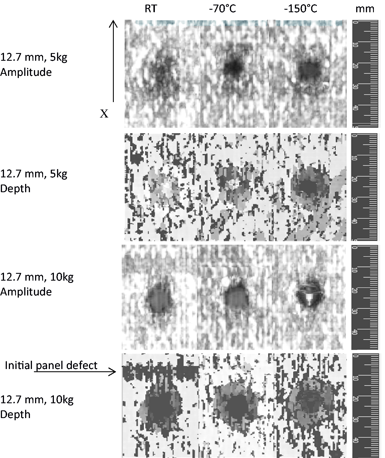
C-scan evaluations of specimens impacted with the 12.7 mm impactor and the 5 kg and 10 kg masses at room temperature, −70°C, and −150°C.
Figure 19 presents C-scan inspections for specimens impacted with the 25.4 mm impactor. For the 5 kg mass, the damaged area increases at cold temperatures. For specimens impacted with the 10 kg mass, the damaged area is slightly wider at −150°C. For specimens impacted with the 20 kg mass, the visual inspection and the residual depth of indentation analyses, indicates that damages are more localized for specimens impacted at cold temperatures. However, the C-scans show similar damaged areas at all temperatures. It indicates the presence of internal damages at cold temperatures not detected visually or with the 3 D image correlation system.
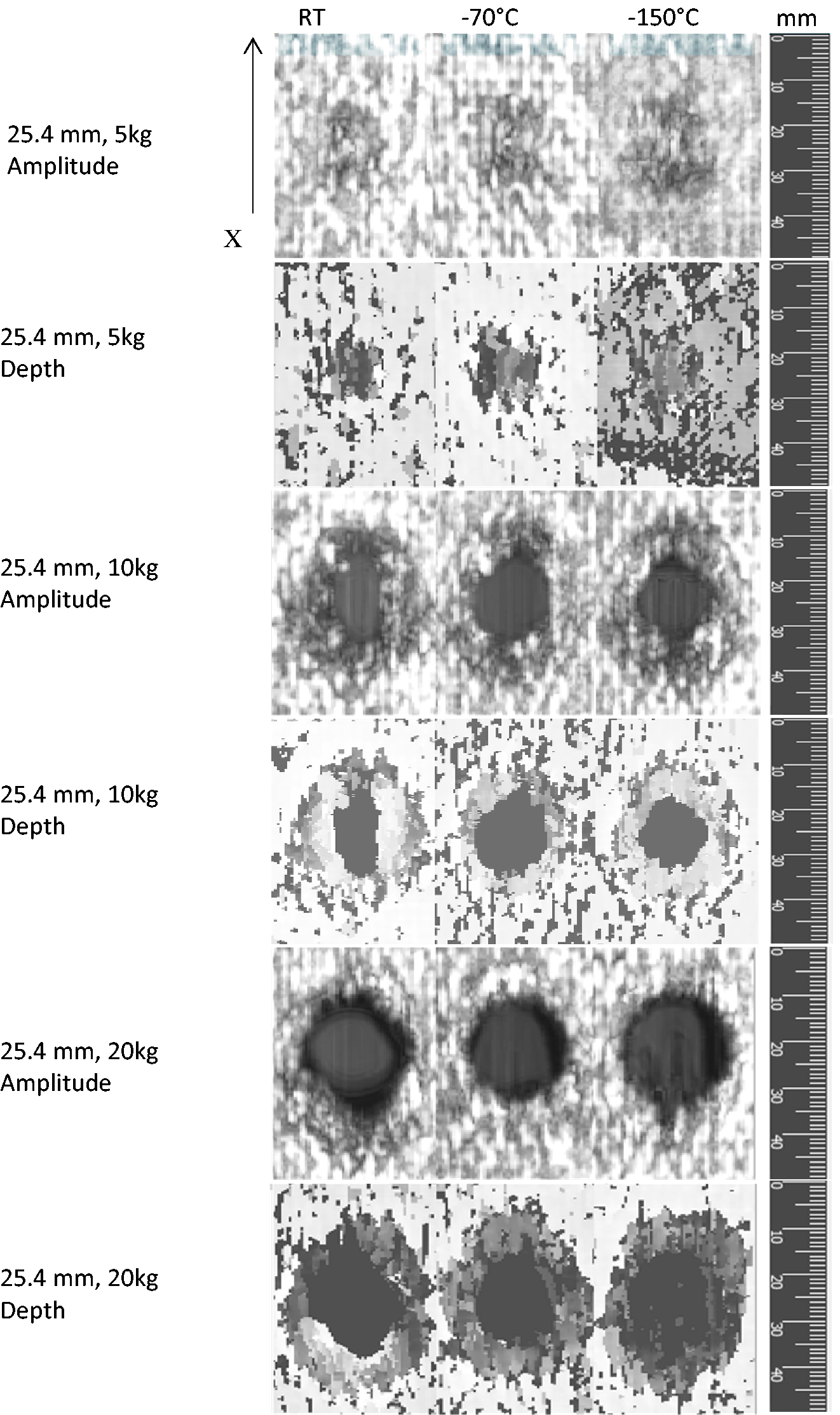
C-scan evaluations of specimens impacted with the 25.4 mm impactor and the 5 kg, 10 kg, and 20 kg masses at room temperature, −70°C, and −150°C.
Cross section observation
In order to fully assess the types of damage induced by impact loadings, a visual inspection of the middle cross section of one specimen for each impact condition was performed. The cross section inspection was performed on the same specimen as the one used for the ultrasonic inspections. Cross section observations were performed along the x- direction, on a section passing through the middle of the damaged area (Figure 20). In order to do so, specimens were cut with a diamond saw cooled with water.
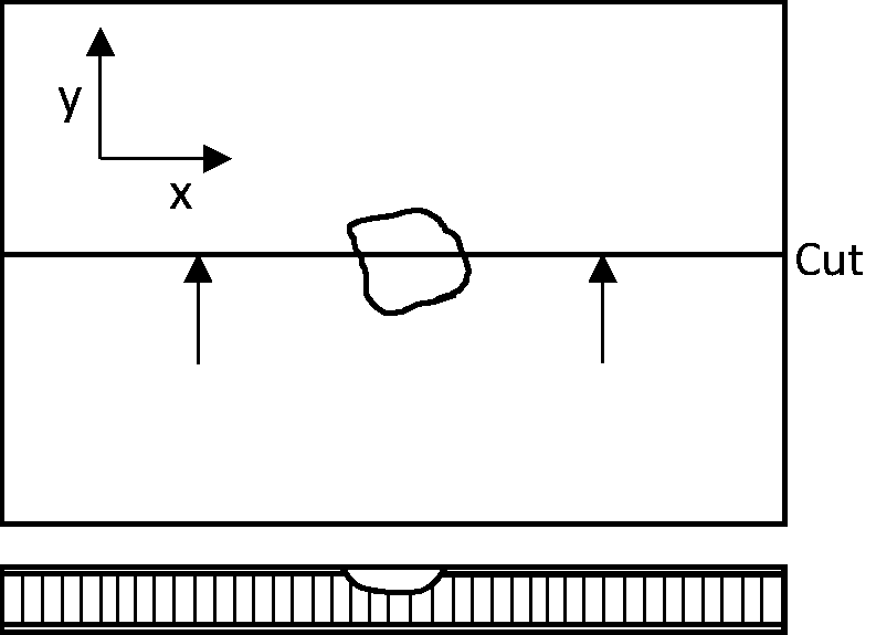
Observed cross section.
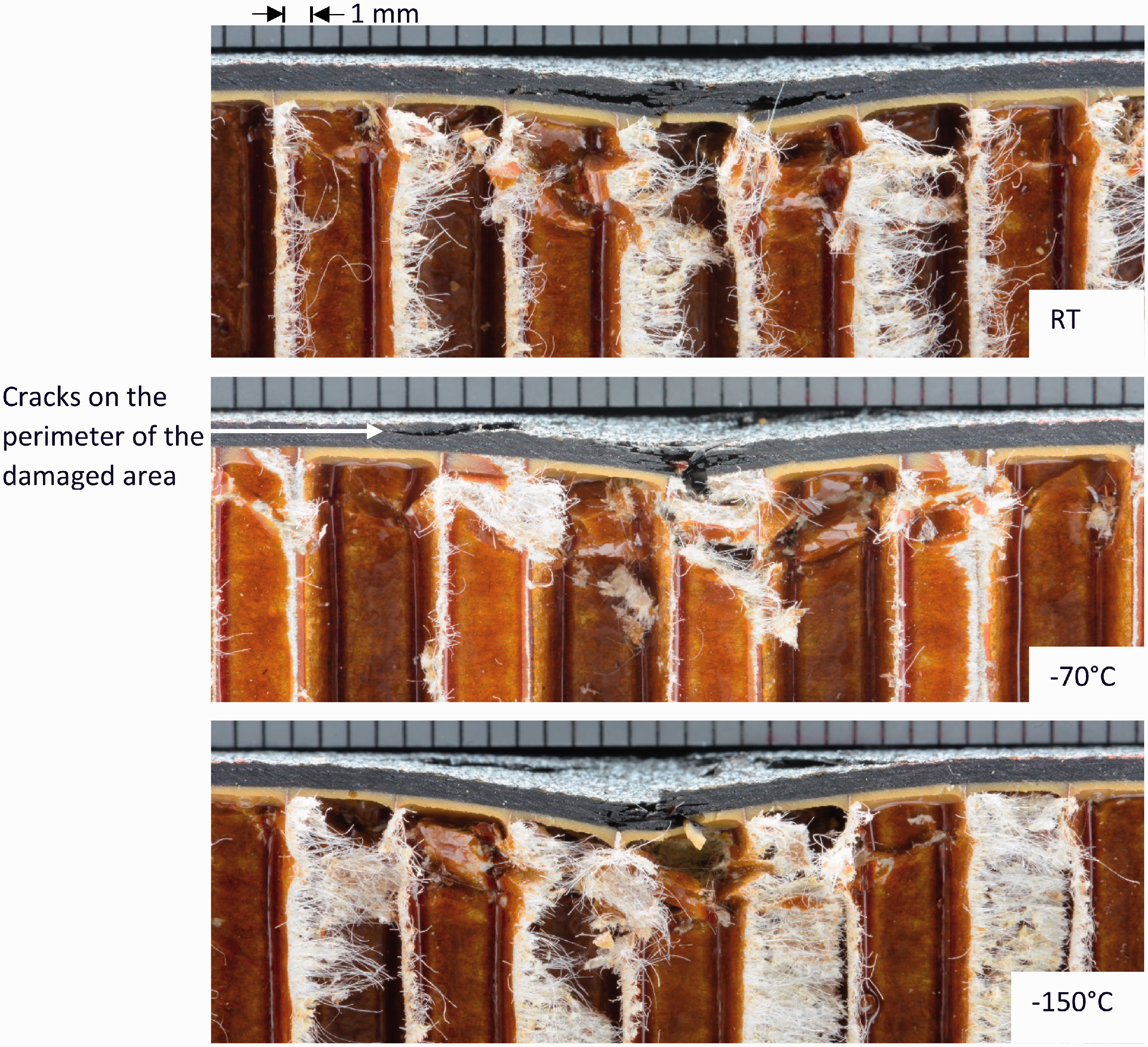
Figures 21 and 22 present the damaged cross section along the x- direction for specimens impacted with the 12.7 mm impactor and the 5 kg and 10 kg masses respectively. For the 5 kg mass (Figure 21), there are two main types of damage visible in the composite skin: delamination and fiber breakage. There is also core crushing. No delamination between the core and the composite skins was observed. At −150°C, important fiber breakages are observed in the middle of the damaged area and on the perimeter of the damaged area. They explain the major load drops observed at −150°C for that impact condition.
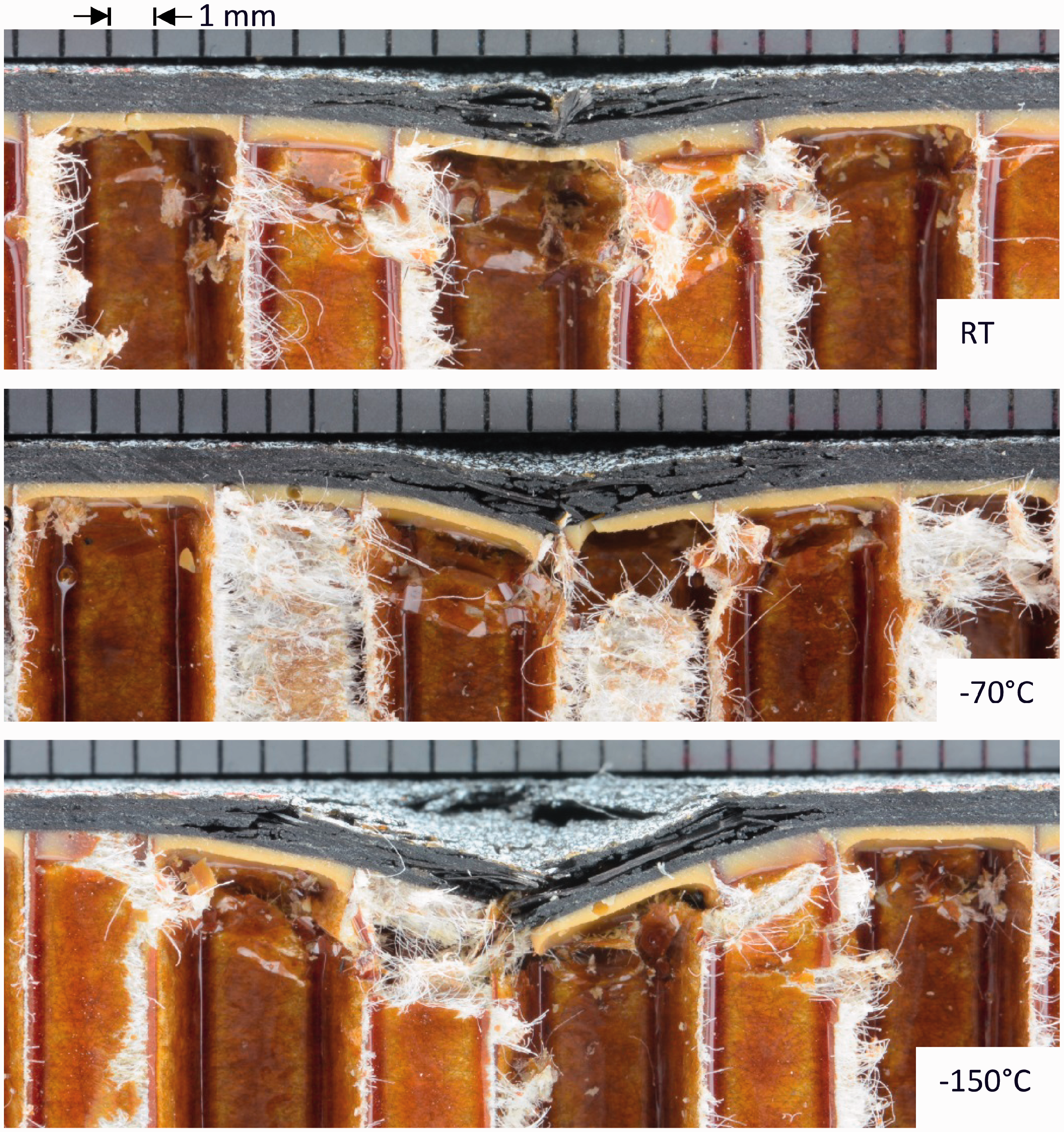
Damaged cross section of specimens impacted with the 12.7 mm impactor and the 5 kg mass.
Damaged cross section of specimens impacted with the 12.7 mm impactor and the 10 kg mass.
For specimens impacted with the 10 kg mass (Figure 22), there is a perforation of the top skin. The cross section observations show that there are important delaminations in the vicinity of the hole at all three temperatures as it was detected by the C-scans inspections. For this impact condition, there is also no debonding between the core and the composite skins. At −150°C, although damage on the bottom skin has been detected with the 3 D digital image correlation analysis and the ultrasonic inspections, it is not visible to the naked eye on the cross section of the specimen. For both impact conditions, with the 12.7 mm impactor, damages observed on the cross sections are more severe as impact temperature decreases.
Figures 23 to 25 present the damaged cross section for specimens impacted with the 25.4 mm impactor. For the 5 kg mass (Figure 23), barely visible impact damages were induced at all three temperatures. For this impact condition, there is mostly delaminations and cracks located under the zone of impact, as well as core crushing. Core crushing extends beyond the damage in the composite skin.
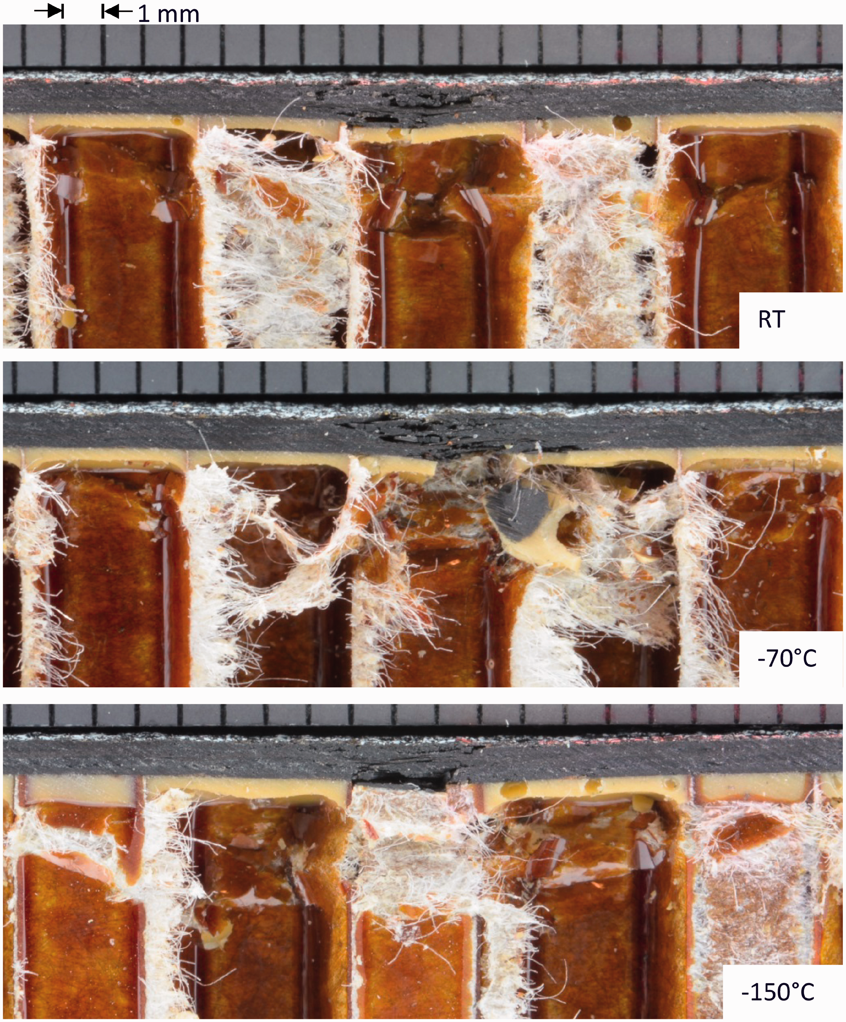
Damaged cross section of specimens impacted with the 25.4 mm impactor and the 5 kg mass.
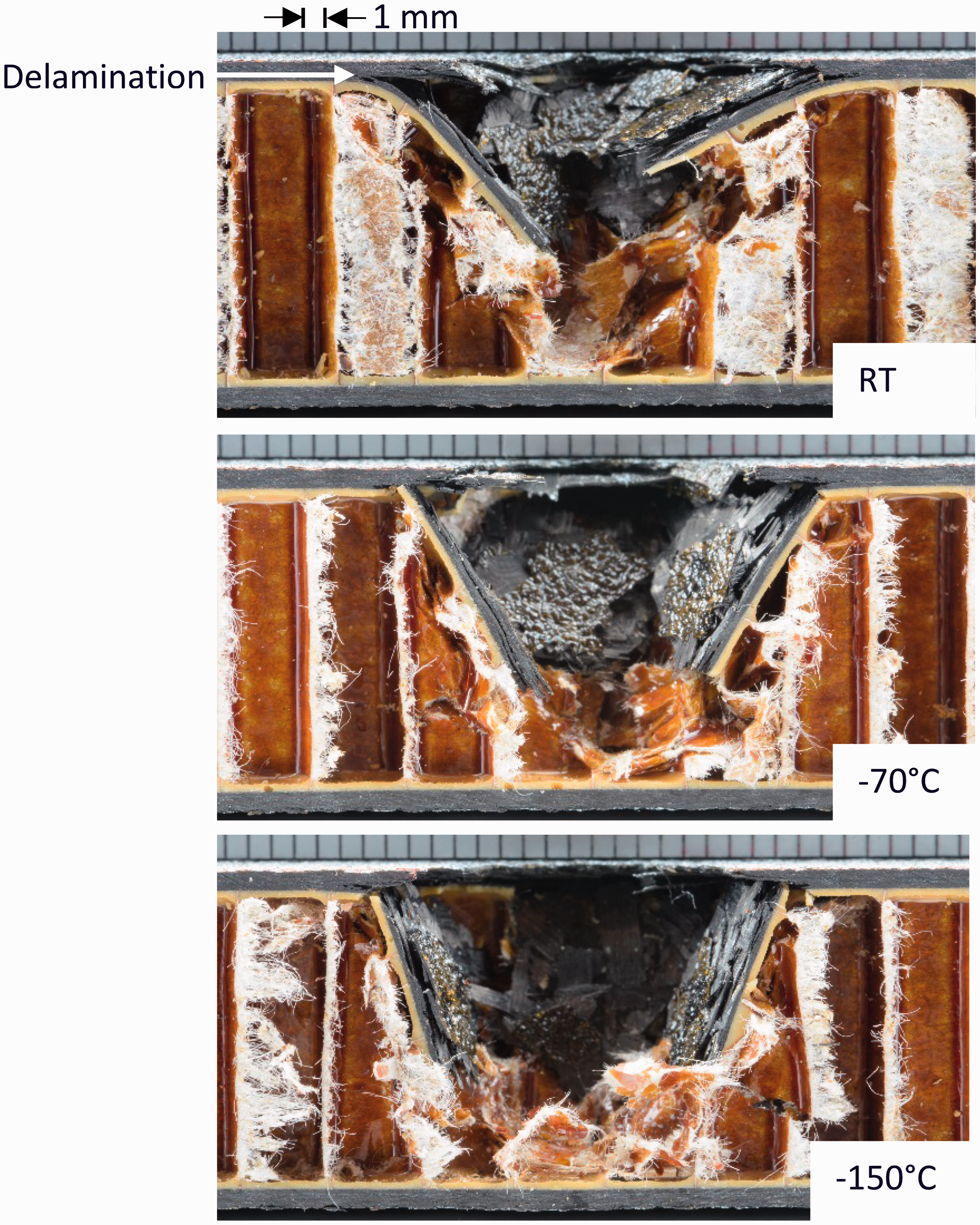
Damaged cross section of specimens impacted with the 25.4 mm impactor and the 10 kg mass.
Damaged cross section of specimens impacted with the 25.4 mm impactor and the 20 kg mass.
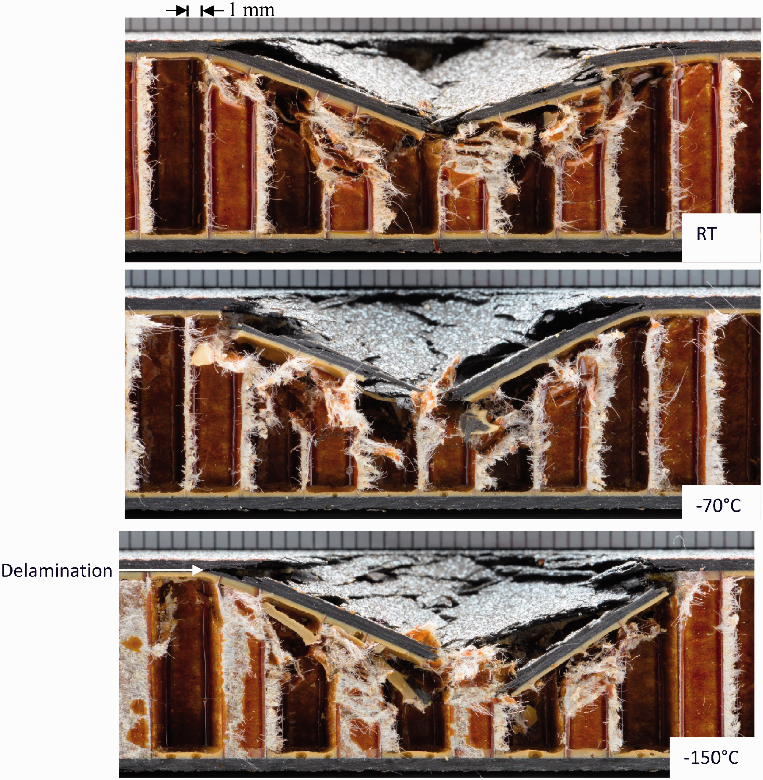
For specimens impacted with the 10 kg mass (Figure 24), the main type of damage observed on the cross section changes at cold temperature. At room temperature, damage in the composite consists mostly of delaminations. Core crushing extends beyond the damage in the composite skin. As temperature decreases, there is more fiber breakage with respect to delamination. Fiber breakage is localized in the middle of the damaged section and covers the entire thickness of the top skin. Damage at cold temperature is also characterized by large cracks on the perimeter of the damaged area. One of those cracks is visible on the cross section at −70°C. At −150°C, none of those cracks are visible on the observed cross section, but they are visible on the top surface of the specimen.
Finally, for the 20 kg mass (Figure 25), the large extent of damage sustained by the specimens at all temperatures are visible. The observation of the damaged cross section shows that delamination propagates beyond the visible damaged area at all temperatures. For all the specimens impacted with the 25.4 mm impactor, no delamination between the composite skins and the core was observed.
Discussion
The results of the herein experimentations show that impact loadings of composite sandwich panels with woven carbon/epoxy skins generally induce more severe damages under extreme cold conditions. Those results are in accordance with the results obtained by Elamin et al. [48] for carbon/epoxy sandwich panels with a PVC foam core impacted between room temperature and −70°C. They observed an increase in damages at cold temperatures, as well as a reduction of the loads on the impactor. The increase in damages at cold temperatures is also in accordance with previous studies on impact of carbon/epoxy laminates at −150°C [31,34,39].
The results of the impact tests, for specimens impacted with the 12.7 mm-diameter impactor combined with the 10 kg mass, show that it requires less energy to perforate the composite top skin at cold temperatures. For this impact condition, as temperature decreases, the core indentation increases. At −70°C and −150°C, there was still energy left in the impactor to reach and impact the bottom skin. It can also be seen in the energy history curves (Figure 12). The energy as a function of time is highly influenced by temperature for this impact condition. The fact that it requires less energy to perforate the top skin at cold temperature is an indication of the effect of temperature on the composite skins. For this impact condition, there are two main damage modes for the composite skin: fiber breakage and delamination. Previous tests, performed by the same research group, on the effect of extreme cold temperatures on the mechanical behavior of composite laminates showed that the tensile strength is negatively affected by cold temperatures [4], which could be an explanation for the more severe damages at cold temperatures. As for the delamination, studies have looked at the effect of extreme cold temperatures on delaminations under mode I and II [6–10]. Kalarikkal et al. [9] studied the effect of cryogenic temperatures on the mode I fracture toughness of carbon fiber reinforced plastic laminates. They studied laminates with unidirectional plies and one laminate with woven plies. For the laminates with unidirectional plies, they observed an important decrease in interlaminar fracture toughness at cryogenic temperature. For the woven laminate, they measured a higher interlaminar fracture toughness at cryogenic temperature. However, the crack path changed at cold temperature. The crack propagated through the adjacent plies, which could explain the increase in interlaminar fracture toughness and also makes impossible to transpose that result for delamination analysis. A decrease in interlaminar fracture toughness at cold temperatures was also observed by others [6,8–10]. The decrease in interlaminar fracture toughness is a clear indication that delamination requires less energy at cold temperatures to propagate. This is another explanation for the more severe damage at cold temperatures. This conclusion can be applied to all of the impact conditions in this work as delamination was always one of the main damage modes.
For specimens impacted with the 25.4 mm impactor, the absorbed energy was not influenced by temperature changes. However, the results showed an increase in damages with temperature decreasing, especially at −150°C. It means that damage required less energy to develop at −150°C, therefore there is more energy available to further damage the specimens. A similar conclusion was made by Gomez-del Rio et al. [39] for carbon/epoxy laminates impacted at room temperature and −150°C. It means that the absorbed energy only is not a good metric to evaluate the damage induced by impact loading under various temperatures since temperature will affect the energy required to produce damage. Analyses of the absorbed energy as a function of impact temperature must be done in conjunction with damage evaluation.
An explanation for the more severe damage at cold temperature is the decrease in matrix toughness. The matrix behavior is highly influenced by temperature. It is more fragile at cold temperature. The strength and the rigidity of the matrix are higher, but the matrix undergoes less deformation before failure. It means that although the matrix has a higher strength at cold temperatures, because its toughness decreases, it requires less energy altogether to break the matrix. The effect of matrix toughness on the low velocity impact behavior of composite laminates has been studied by Cartier and Irving [52]. Their work showed that low toughness matrix will sustain more delaminations than high toughness matrix especially at the onset of delamination. Moreover, they observed that the threshold load for delamination is also related to matrix toughness. A low matrix toughness is associated with a lower threshold load. Here, the delamination threshold load is very difficult to identify because damages are induced both in the composite skins and the Nomex core. However, the results of Cartier and Irving [52] confirm the important effect of temperature on delamination, since temperature affects the matrix toughness.
The results show that specimens impacted with the 12.7 mm impactor are more sensitive to the effect of temperature than specimens impacted with the 25.4 mm impactor. For the latter, damage is less localized. The global panel behavior is more solicited, so the core behavior plays a more important role. Core crushing covers a larger area. Whereas for the 12.7 mm impactor, composite damage is more pronounced and core damage is more localized in comparison with the 25.4 mm impactor for a given mass. It emphasises the importance of the effect of temperature on the composite skin behavior. Moreover, for the 12.7 mm impactor, the cell size is more than one third of the impactor diameter. It explains that core damage is more localized for that impactor, and that once the top skin is perforated the impactor is easily able to perforate the core as well.
The effect of temperature on the out-of-plane compressive behavior of the Nomex core has been studied by the same research group [4]. The results of the study show an increase in out-of-plane compressive modulus, as well as maximum out-of-plane compressive strength, at cold temperatures. A minor reduction of the plateau strength following the collapse of the cell wall was also observed. Those phenomena probably contribute to a small extent to the impact behavior of the sandwich panel at cold temperatures.
Quasi-static indentation tests were performed as well as impact tests. Generally for low velocity impacts, it is assumed that the behavior under impact is similar to the behavior under quasi-static loading, which is an important assumption for simulation purposes. Here, the same fixture was used for both types of tests. However, for the quasi-static indentation tests, specimens were simply resting on the steel support, while for the impact tests, specimens were clamped using a pneumatic system. Figure 26 shows a comparison between the load-displacement curves at room temperature and at −150°C for the impact tests with the 25.4 mm-diameter impactor combined with the 5 kg, 10 kg, and 20 kg masses and for the quasi-static indentation tests with the 25.4 mm-diameter indentor. The panel behavior is slightly stiffer during impact loading. As temperature decreases, the same tendencies are observed. This conclusion applies for all of the impactor masses tested. Indeed, the increase in the impactor mass leads to higher displacements of the impactor, but the beginning of the load-displacement curve is similar for all the impactor masses. Similar conclusions are obtained with the 12.7-mm diameter impactor except at −150°C, where both behaviors are similar. Although, the boundary conditions were different for the two tests, the effect of cold temperatures on the load displacement curves is similar. Reductions of the loads were measured at cold temperatures, and an increase in residual depth of indentation was observed for both types of tests at −150°C.
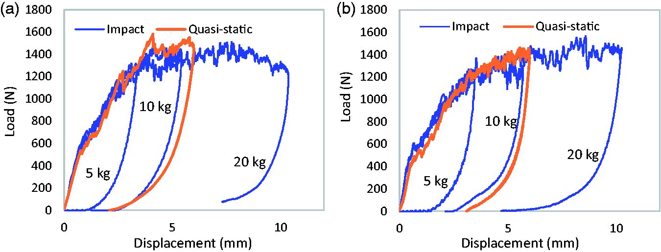
Load-displacement curves at a) room temperature and b) –150°C for quasi-static indentation tests with the 25.4 mm indentor and impact tests with the 25.4 mm impactor combined with the 5 kg, 10 kg, and 20 kg masses.
Conclusion
The effect of extreme cold temperatures on the low velocity impact behavior of composite sandwich panels was studied. Impact tests and quasi-static indentation tests were performed at room temperature, −70°C, and −150°C. Visual inspections, residual indentation depth measurements, ultrasonic C-scans and cross section observations of the specimens were performed to evaluate damage induced under different temperatures and impact conditions.
The results of the impact tests show that the size of the impactor has an influence on the effect of temperature on the low velocity impact behavior. Indeed, results show that specimens impacted with the smallest impactor are more sensitive to the effect of temperature. For specimens impacted with the 25.4 mm impactor, the effects of temperature on the load history and load-displacement curves are almost negligible.
Temperature has an important effect on the induced damage under impact loading. As temperature decreases, the amount of damage induced increases. The decrease in matrix toughness at cold temperatures probably plays a major role in that increase. The combined study of the induced damage and the absorbed energy shows that it requires less energy to produce damage under impact loading at cold temperatures for the sandwich panel studied.
The three main types of damage observed in the specimens are delamination in the top composite skin, fiber breakage and core crushing. No delamination between the core and the composite skins were observed on the cross section of the specimens at any temperature and for any impact condition, an important conclusion for numerical model development purposes. It is also an indication that the adhesive used for this study is appropriate for cold temperature applications.
For specimens impacted with the 25.4 mm impactor, the effects of temperature between room temperature and −70°C are almost negligible with respect to the effects of temperature between −70°C and −150°C. It underlines the necessity of testing in an environment as close to the real operating environment as possible. For lunar exploration rovers, testing in an even colder environment should be considered, depending on the areas of the moon the rover is intended to explore and the thermal protection it will have.
The data obtained in this study will contribute to enhance the development of the database for composite structures, especially sandwich panels, impacted in extreme environments. Indeed, there was no data available on impact behavior of composite sandwich panels at temperature as cold as −150°C. As damage increases with temperature decreasing, the next step of the project is to study the effect of those damages on the compression after impact behavior of the sandwich panels in order to evaluate their remaining mechanical integrity as a function of impact temperature. The results of the impact tests will also be used for the validation of numerical models.
Footnotes
Declaration of conflicting of interests
The author(s) declared no potential conflicts of interest with respect to the research, author-ship, and/or publication of this article.
Funding
The author(s) disclosed receipt of the following financial support for the research, authorship, and/or publication of this article: This work was supported by the Natural Sciences and Engineering Research Council of Canada and the Canadian Space Agency.