
Abstract
The performance of low weight, high stiff multi-materials relies on the interfacial bond quality between the adherends. This study analyses the effect of surface roughness, organosilane treatment and coating with diamond like carbon on the adhesion strength between carbon fiber reinforced composites and an additively manufactured (AM) AlSi10Mg counterpart. Extending applications to sandwich structures, both, bulk and honeycomb structured counterparts were considered. Double-Lap Shear specimens were fabricated in a co-curing process, and further investigated regarding the bond efficiency. Results were compared to the state-of-the-art joints applying an adhesive film layer. It was observed that surface roughness is not pivotal when using such adhesive film. In contrast, higher surface roughness generally tends to promote adhesion strength by promoting mechanical interlocking and increasing the available bond area. Further coating with organosilanes and diamond like carbon increases the surface energy and reduces the contact angle thus improving surface wettability by the matrix resin. In consequence, an improvement of up to 30% in adhesion strength was observed in case of coating the metallic surface with diamond like carbon. Prior surface polishing of the additively manufactured parts does not significantly affect the bond quality and is therefore not recommended.
Keywords
Introduction
Sandwich materials are efficient load-carrying structures and play a key role in many engineering applications, where reduced weight is important. Modern facesheet materials are anisotropic composite laminates or lightweight alloys, having high modulus and strength. In aerospace applications, mainly carbon and glass fiber reinforced polymers are applied. The most common core structures are honeycombs made from different materials, such as resin impregnated aramid fiber paper (Nomex) or aluminum [1].
The bond strength between the facesheet and the core is vital for the overall performance of the panel. Mode I (opening mode due to tensile stress normal to the bond area) and mode II (sliding mode due to shear stress acting parallel to the bond plane) are the most common debonding failure patterns in sandwich structures [2]. One challenge with honeycomb cores is the minimal bond area to the facesheet. Common aerospace graded honeycomb structures have a wall thickness of 60 – 80 µm. A way to ensure proper interfacial bonding is the use of an adhesive layer. During curing at elevated temperatures, the adhesive’s viscosity decreases and flows along the honeycomb walls, creating an adhesive form fit. Another method relies on the excess resin in the uncured prepregs to wet the honeycomb walls. This method is currently under investigation, as it would not only benefit from weight reduction, but also lower the manufacturing costs and time. It was proven that large and symmetric fillets increase the shear strength in composite panels, due to the higher bonding area [3].
Surface treatments are often applied to promote bonding. Grid blasting removes weakly bonded boundary layers and increases the effective surface area of the adherend [4]. Improved mechanical interlocking results in significantly higher adhesive strengths [5,6]. Kromer et al. [7] investigated micro roughness created on aluminum surfaces by a pulsed fiber laser. Resulting pitting of 60 µm depth and 50 µm diameter reduced crack propagation in the adhesive due to barriering effects induced by the pits. An adhesion strength enhancement of up to 300% in contrast to an untreated surface was observed.
Tang et al. [8] embedded a sub-millimeter cellular structure in an additively manufactured (AM) steel surface, to improve bonding in metal-thermoplastic hybrids. The cellular structure was in form of interconnected tunnels of 0.4 mm diameter including vertical holes of 0.7 mm diameter. The mechanical interlocking was achieved when the thermoplastic melt solidified inside and around the textured surface. A maximum shear strength of 17.7 MPa was achieved.
Aluminum forms a stable passivating oxidation layer, up to several hundreds of nanometres in thickness, when exposed to the atmosphere. The oxide layer has a comparatively low surface energy and correspondingly poor wettability by adhesives. This makes a surface preparation before bonding necessary. The theoretical surface energy of aluminum lies around 500 to 1000 mJ/m2 [9], whereas real (passivated) surfaces range from 40 to 60 mJ/m2 [6,10], depending on the surface roughness, cleaning procedure and alloy constituents. Commonly applied surface treatments include chromatic acid and phosphoric anodization, or chromic-sulfuric or sulfuric-boric acid etching [11,12]. While the adhesive strength and the durability of joints are improved, these approaches can be tedious and involve environmentally hazardous chemicals.
A promising environmentally friendly pre-treatment is found in organofunctional silanes. The bifunctional molecule with a central silicon atom, interacts with the oxidized metal surface creating a film of interlinked siloxane molecules, usually in the thickness range from ten to hundreds of nanometres [13]. This three-dimensional network is resistant to hydrolysis, offering corrosion protection [14]. At the organosilane-epoxy interface, covalent bonds are established. Monden et al. [5] reported the improvement in interlaminar shear strength in steel-carbon fiber reinforced polymer (CFRP) specimens of 40% over a reference joined without organosilane treatment.
Diamond Like Carbon (DLC) coatings are thin layers (1 – 10 µm in thickness) of amorphous carbon with sp2 (graphite-like) and sp3 (diamond-like) hybridized bonds. A major content of hydrogen (up to 50%) can further be comprised [15]. The hardness and wear resistance of the coating is associated to the hybridization state and the content of the non-carbon elements. The surface energy of DLC coatings varies from 20 to 50 mJ/m² [16]. Highest polar contributions (γd = 16 mJ/m²) are obtained when the DLC coating has low H-content. This rather moderate surface energy lies within the range of that known for metallic surfaces [17]. Monden et al. [18] reported a 50% improvement in interfacial fracture toughness for a DLC coated steel, bonded to epoxy based CFRP. The highest adhesion enhancement was obtained with DLC coatings with high silicon content. Furthermore, the DLC coated samples showed a significant improvement in corrosion resistance by reducing corrosion current densities by three magnitudes compared to an uncoated steel.
This study investigates the combined effect of surface roughness and coatings on the bond quality of an additively manufactured aluminum honeycomb and bulk structures adhered to a carbon fiber reinforced polymer facesheet.
Materials and methods
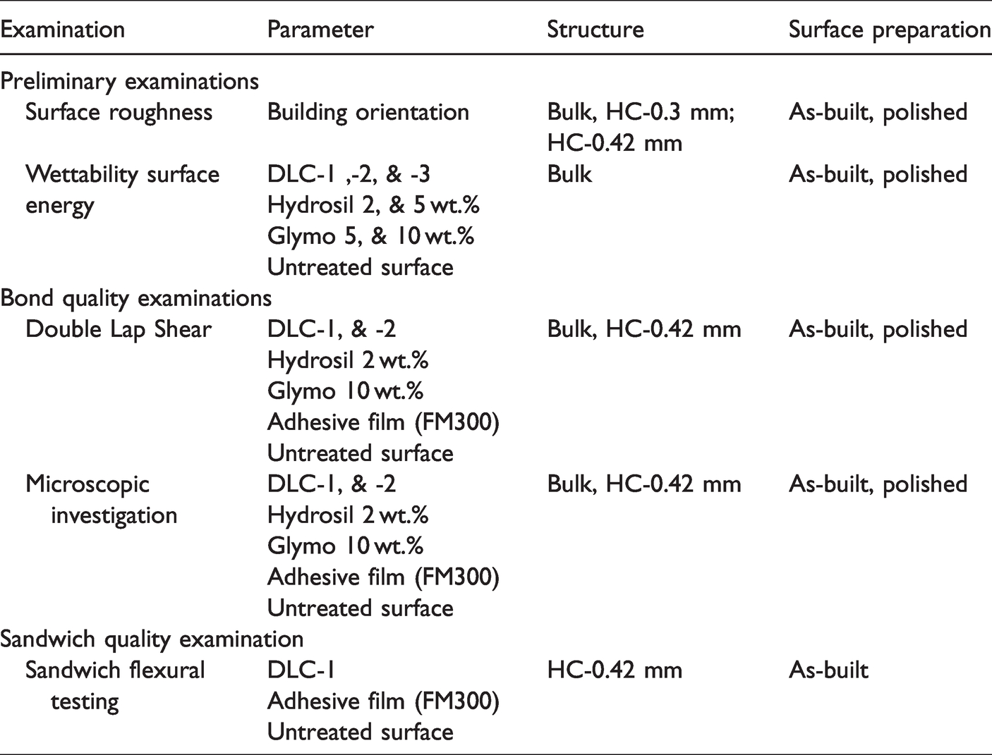
Table 1 summarizes the samples and investigations performed in this study. First the wettability of AM as-built (unpolished) and polished aluminum surfaces was identified at different fabrication angles. Further, the coating conditions using organosilanes and DLC were determined. The bond strength was then examined for both honeycomb structures and bulk material adherents through a Double-LapShear (DLS) test. The best performing coating-roughness combination was then examined in a sandwich configuration using 3-point bending. Untreated samples and others joined using an adhesion film were used as a reference.
Examination methods of the preliminary and main bond quality investigations.
Materials
AlSi10Mg provided by EOS GmbH with an average grain size of 60 µm (mean particle size distribution 20 to 63 µm) was used for the additive manufacturing of the honeycomb core structures. Carbon fiber prepreg HexPly® M18/1 from Hexcel Corporation was applied for the fabrication of the composite facesheets. It is a high performance, self-extinguishing, prepreg material qualified for aerospace applications. The reinforcement is a carbon fiber fabric (G939) with a plain textile weave at 55% fiber volume fraction.
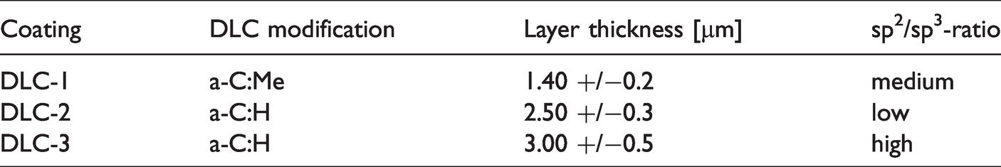
Organosilanes and DLC were used as treatments for the AM surfaces. Two different organosilanes Dynasylan® Glymo and Hydrosil 2926 were supplied by Evonik Industries. Further, different types of DLC coatings were kindly provided by Kuhn Beschichtungen GmbH, Germany. The coatings were chosen in a way to have different sp2/sp [3] ratios, different chemical dopants as well as varying film thicknesses. Accordingly, different wetting behaviours and influence on adhesion were expected. The main specifications of the three DLC coatings, denoted as DLC-1, DLC-2 and DLC-3, are summarized in Table 2. FM300 thermosetting adhesive film of 150 µm thickness (171 g/m² areal density) from Solvay S.A. was used as a reference for bonding.
Main specifications of the DLC coatings under investigation.
Preliminary examinations were carried out to evaluate the wettability of the AM AlSi10Mg surface by the resin. For this purpose, the epoxy resin RTM6 from Hexcel Corporation was applied. The selection is based on the similarity to the matrix system M18/1 of the aforementioned prepreg material, which is not separately available.
Sample preparation
Laser beam melting
In preliminary investigations, the effect of the building orientation on the surface roughness and wettability of both bulk and thin-walled faces was studied. Preliminary samples and cores made of AlSi10Mg were fabricated by Laser Beam Melting (LBM) using an Aconity One machine, equipped with a 200 W laser. Parts were manufactured at a layer height of 50 µm and an infill laser scan speed of 1150 mm/s under argon gas atmosphere. The samples (Figure 1) included 0°, ±45°, and 90° planes, as well as a bulk surface and a honeycomb structure (cell diameter: 6.4 mm, nominal wall thickness: 100 and 300 µm).
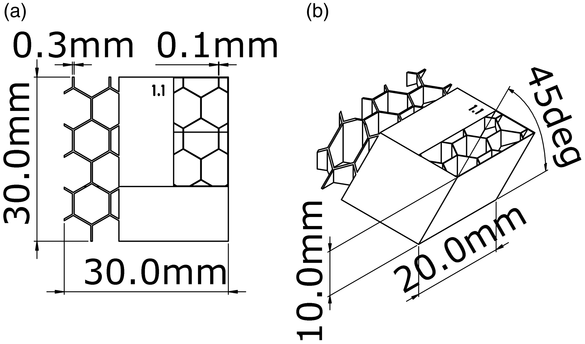
AM specimen to assess surface roughness versus inclination angle (a) top view and (b) isometric view.
To study the effect of surface roughness and surface treatment on the bond strength between CFRP and AM structures, DLS samples were prepared. Both bulk (Figure 2(a)) and honeycomb (Figure 2(b)) core structures were fabricated by LBM. A rib of 3 mm thickness was introduced to the honeycomb section to increase the structural rigidity. The honeycomb cell diameter was 3.2 mm with a wall thickness of 300 µm.
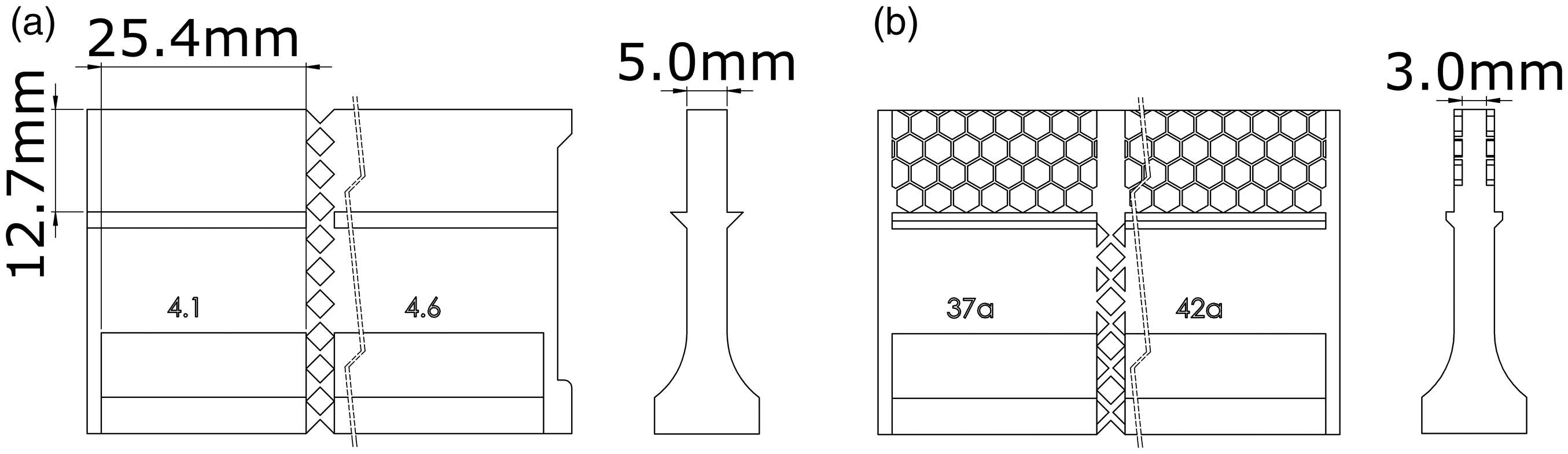
AM core segments for DLS samples as (a) bulk and (b) honeycomb structures.
Organosilane coating
Samples were first cleaned with isopropanol, followed by acetone, each for 10 min and subsequently rinsed with distilled water. Aqueous solutions with different organosilane concentrations of 5 and 10 wt.% for Glymo and 2 and 5 wt.% for Hydrosil 2926, were prepared in an ultrasonic bath by agitation for 20 min, until a full hydrolysis is obtained (recognized by the disappearance of oily streaks). In case of the Glymo solution, acetic acid was added to lower the pH-value to 5, to accelerate full hydrolysis according to Monden [19]. The samples were then dip-coated in the respective solution for 10 min, in which the first 5 min were assisted by ultrasonic vibration to guarantee complete wetting. After coating, the samples were blow-dried with compressed nitrogen and placed in an oven to dry at 110 °C for 20 min.
DLC coating
AM parts were cleaned in an alkaline solution with the aid of ultrasound for 20 min, rinsed with distilled water and left to dry. The samples were then introduced to a vacuum chamber and placed on a rotating substrate holder. PVD/PACVD-processes were applied to deposit the DLC coatings given in Table 2 at temperatures of 150 to 180 °C.
Co-curing of panels and sample production
For the assessment of the interfacial bond between the additively manufactured AlSi10Mg part and the CFRP skin, DLS samples were fabricated in a co-curing process as illustrated in Figure 3 (as a modification of the co-bonding process described in [20]. Modifying ASTM D3528 the overall sample length was reduced to 40.2 mm to minimize the manufacturing effort. Also, only the overlap region of the core (S1) was additively manufactured, while for the remaining length (S2) a corundum blasted commercial aluminum panel was implemented. To prevent frontal adhesion between both segments, a PTFE spacer was applied. A shoulder section was further introduced to the AM segment for easier sample clamping into the testing machine. To compensate the height difference induced by this shoulder section, aluminum toolings, treated with release agent (Loctite Frekote 700-NC), were used as a jig.
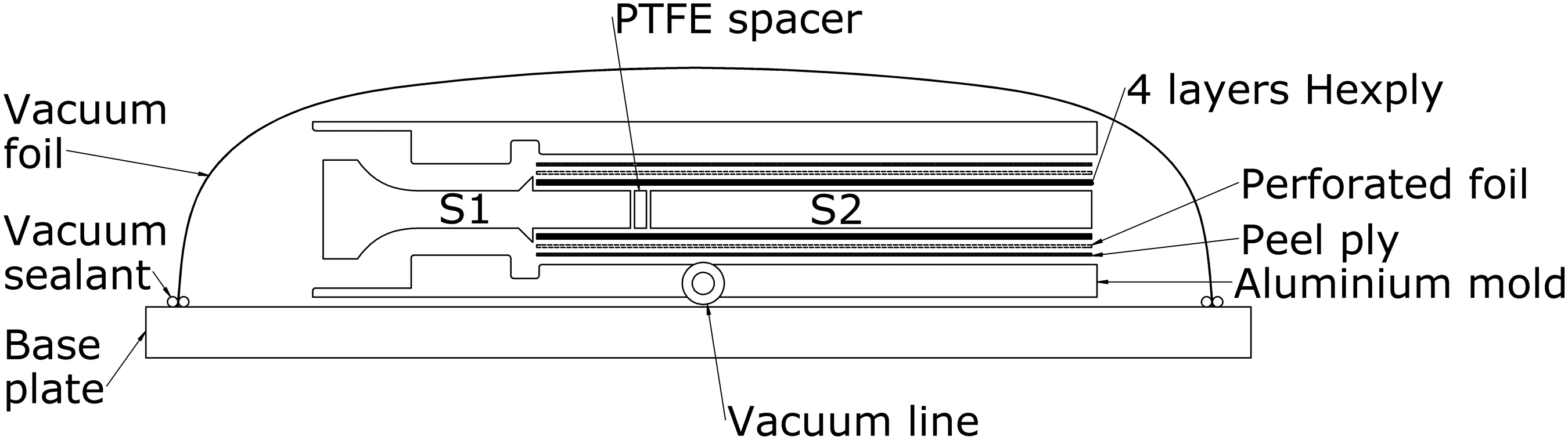
Explosion drawing of the DLS manufacturing lay-up sequence.
In a first step, oversized peel-ply and subsequently a perforated release film were draped over the mold and taped onto the baseplate to avoid displacement. A compacted stack of prepreg material (114.7×173.4 mm³) was positioned onto the mold and similarly taped to the baseplate. Then, the AM segment (S1), the PTFE spacer, and the bulk aluminum segment (S2) were placed into the jig. Care was taken to align the edge of S1 to the notch in the tool. The core setup was covered by the upper skin layers in such a way to obtain a symmetric sandwich layup. Perforated release film and peel ply were taped on top. The upper mold was positioned, and all sharp edges were covered with non-woven before vacuum bagging. The assembly was then cured under a constant vacuum pressure of 10 mbar. The curing temperature was first kept at 120 °C for 2 h and then heated up to 180 °C for another 2 h up to final curing. Panels were finally cut to samples with an overlap length of 12.7 mm, a width of 25.4 mm, and an overall height of 142.2 mm.
Sandwich panels (100×168×12 mm³) were fabricated in a similar way. Due to the plane geometry of the panels, the use of a jig became unnecessary. Similarly a further sample series, having an FM300 adhesive film layer between the core and the facesheets was prepared. Sandwich panels were finally cut into bending samples (100×24×12 mm³).
Testing
Surface roughness
To analyze the AM topology of both honeycomb and bulk surfaces, the surface roughness of all faces (except the base face) of the specimens presented in Figure 1 was measured with a laser microscope Keyence VK9700. Optical profilometry was conducted at a magnification of 20x and evaluated with the software VK-Analyzer from Keyence. The arithmetic roughness Ra was averaged for three measurements over a quadratic measuring field of 200×200 µm².
Wetting
To assess the wetting capabilities of the DLC and organosilane coatings, contact angle measurements with RTM6 epoxy resin were conducted on a measuring system OCA 15EC, from DataPhysics Instruments GmbH, Germany and the corresponding SCA20 software. A disposable syringe of 1 ml capacity with a metallic cannula of 1.2 mm outer diameter was applied for dosing. The resin was kept in the syringe at 80 °C. At the start of each measurement, a drop volume of 5 µl with a dosing rate of 0.5 µl/s was carefully placed onto the polished and preheated (80 °C) bulk substrate. The substrate was then heated with a rate of 2 °K/min to 120 °C. Reaching this temperature, the contact angle was measured optically using a microscopic camera. The temperature profile was selected based on the recommended curing cycle of the prepreg material under consideration. The measurements were repeated twice per coating and the average contact angle was calculated. An uncoated AlSi10Mg surface was examined as a reference. All samples were cleaned prior to measuring according to the above-mentioned procedure.
Surface energy
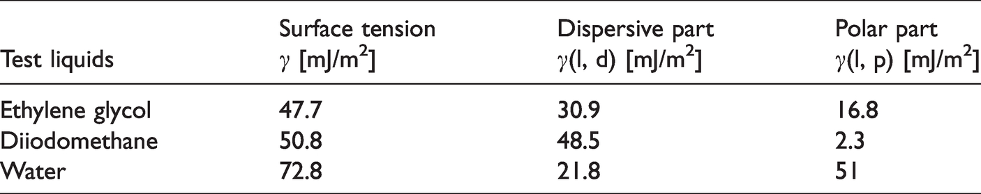
The surface energy of the coatings under investigation was measured according the OWRK-method at room temperature on polished surfaces. The test liquids used were ethylene glycol, diiodomethane, and demineralized water. The values for the dispersive and polar shares are presented in Table 3 [21]. Three test replicates were carried out for each coating.
Surface tension values of the used test liquid [21].
Double-lap shear test
The adhesive strength between the AM structure and the CFRP was measured under pure shear to assess the effect of surface treatment. Both bulk and honeycomb structures were considered in an as-built and in a polished state. Polishing eliminates the effect of surface roughness and enables the recognition of the pure effect of chemical treatment on bond strength. Coatings of highest and lowest wettability results were selected for DLS testing, with regard to epoxy wetting (Table 1). Examination was carried out based on the ASTM D3528 standard at room temperature using a universal testing machine Allround Table top Z050 from ZwickRoell, at a crosshead speed of 1.27 mm/min (0.05 inch/min) and a pre-force of 100 N. A frontal and profile view of a ready to test DLS sample can be seen in Figure 4(a) and (b). Figure 4(c) shows the sample and the testing setup. The average of five test replicates was calculated.
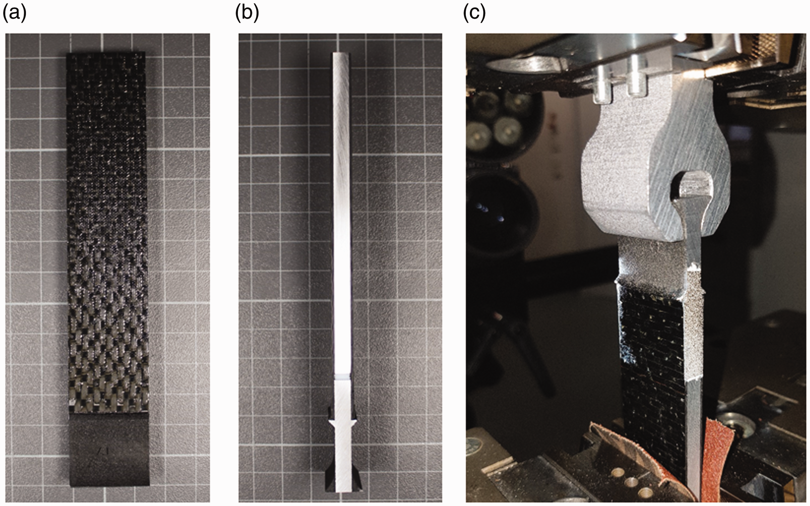
DLS sample (a) top view, (b) side-view and (c) sample clamped into testing machine.
Micrographs of the bondline and fracture surface were carried out using a Leica DM4000 light microscope and Leica DM80 stereomicroscope to evaluate the bond quality and the failure mechanism.
Flexural test
3-point bending tests, according to the standard ASTM C393 were carried out, to determine the flexural strength of AlSi10Mg-CFRP sandwiches. Here, the best surface roughness-coating combination from the DLS testing was chosen and compared to the references having untreated AM-surface and FM300 adhesive film, respectively. Tests were carried out on the Z050 machine at a span length of 50 mm and a crosshead speed of 0.3 mm/min and a pre-load of 200 N.
Results and discussion
Surface roughness
Figure 5(a) presents the effect of building orientation on the surface roughness (Ra). The high scattering can be attributed to unfused particles adhering to the surface. Highest scattering is observed in overhanging −45° surfaces. In general, the bulk surfaces show higher roughness than the honeycomb variants. An exception is observed for horizontal builds (0° orientation). In this case, the widespread laser exposure minimizes the risk of adhering particles. The locally induced heat after exposure could spread evenly before the next powder layer is applied. A small risk of balling however does remain. In case of honeycomb, no notable different roughness levels could be detected amongst the various surface angles under consideration. Based on these findings the 90° buildingorientation was considered for further investigations related to the wettability studies.
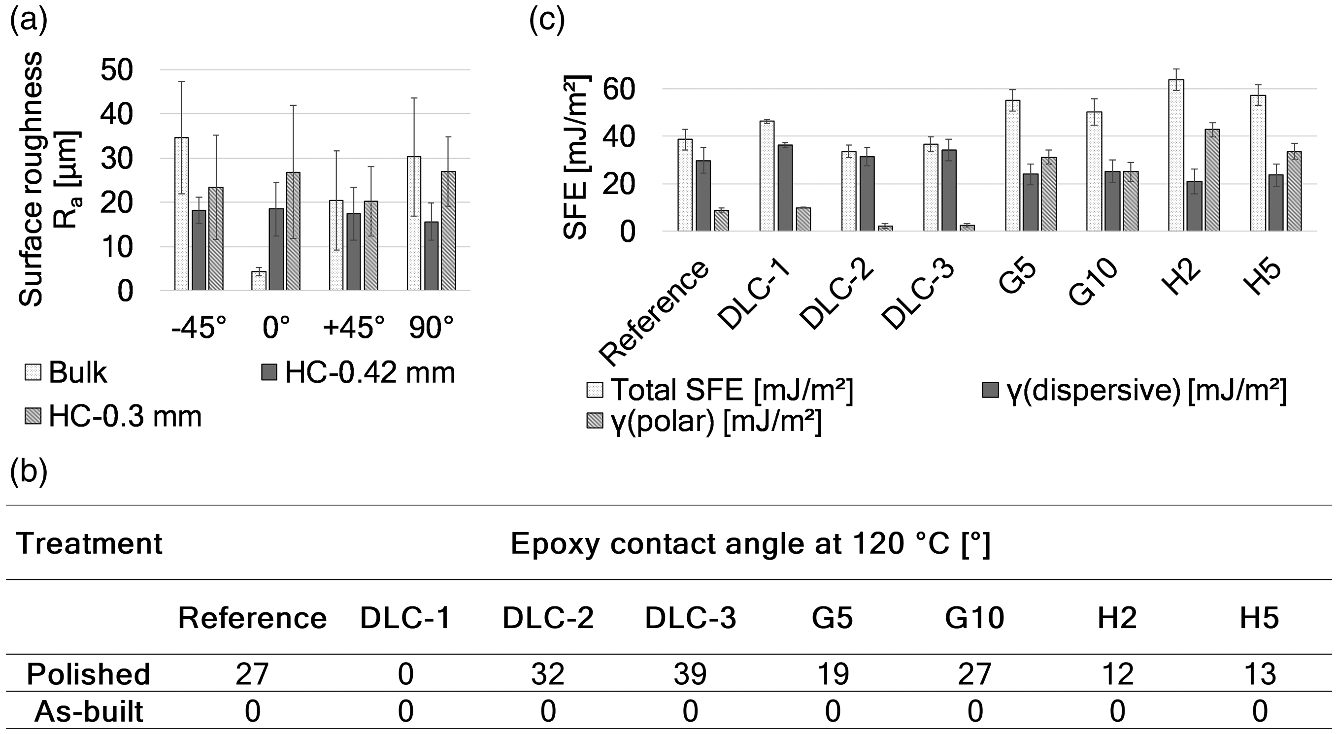
(a) Surface roughness Ra as a function of the building orientation of the uncoated as-built bulk and honeycomb structures. (b) Contact angle of epoxy on coated substrates with polished and as-built roughness levels. (c) Surface energy and the underlying polar and dispersive components of the coated and uncoated AlSi10Mg surfaces.
Effect of coating on surface wettability and surface energy
The coatings under consideration were screened for their best wetting capabilities in terms of contact angle and surface energy measurements. These investigations were carried out on coated polished, and as-built AM bulk structures. Contact angle results are presented in Figure 5(b). Generally, it can be noted that the higher surface roughness reduced the contact angle and thus enhanced surface wettability by the resin. Applying DLC-1 to the polished surface was also able to induce complete wettability.
The surface energy of the coated surfaces is further illustrated in Figure 5(c). The measured values for the uncoated surface lie in agreement with literature values [6,10] and denote the presence of a pronounced oxide layer. Considering the DLC-coatings, the maximum attained surface energy of 46.3 mJ/m² was reached in case of the DLC-1. This might be attributed to higher polar share in contrast to the other DLC-coatings. Comparing the polar and dispersive components of the coatings to those of the RTM6 resin (dispersive: 30.2 mJ/m2 and polar: 10.7 mJ/m2), best compliance is found in case of the DLC-1 coated and the reference surface. This explains the aforementioned complete wettability of the surface by the resin.
Regarding organosilane treatment, the 2 wt.%-Hydrosyl (H2) coating achieved the highest overall surface energy (63.7 mJ/m²). Its high polar part might be attributed to the high number of functional groups in the organosilane molecule. Despite the higher concentration applied in case of H5, the measured surface energy of the polar parts was lower. The authors assume that the higher availability of soluble organosilane molecules formed an organosilane network, in which polar docking sites were blocked.
Adhesive shear strength
Bulk surfaces
The bond shear strength and modulus of DLS-samples under implementation of the various pre-treatments is presented in Figure 6(a) and (b). In accordance with the previous results, polishing did not contribute to the increase of the shear strength. For polished surfaces, an improved bond quality (30% relative to the uncoated and polished reference) was only achieved through the implementation of the adhesive layer. Similarly, for as-built surfaces, the highest shear strength of 32.58 MPa was reached with the FM300 adhesive film, outperforming the reference by 45%. The DLC-1 coating was found to enhance the shear strength by 30%. The DLC-2 coating did not significantly affect the adhesion. The Glymo-10% and Hydrosil-2% organosilane treatments improved shear strength by 15% and 10%, respectively. Generally, the as-built series tended to have an average modulus of around 6% higher than that of the polished samples. However, no significant differences could be detected within the same series.
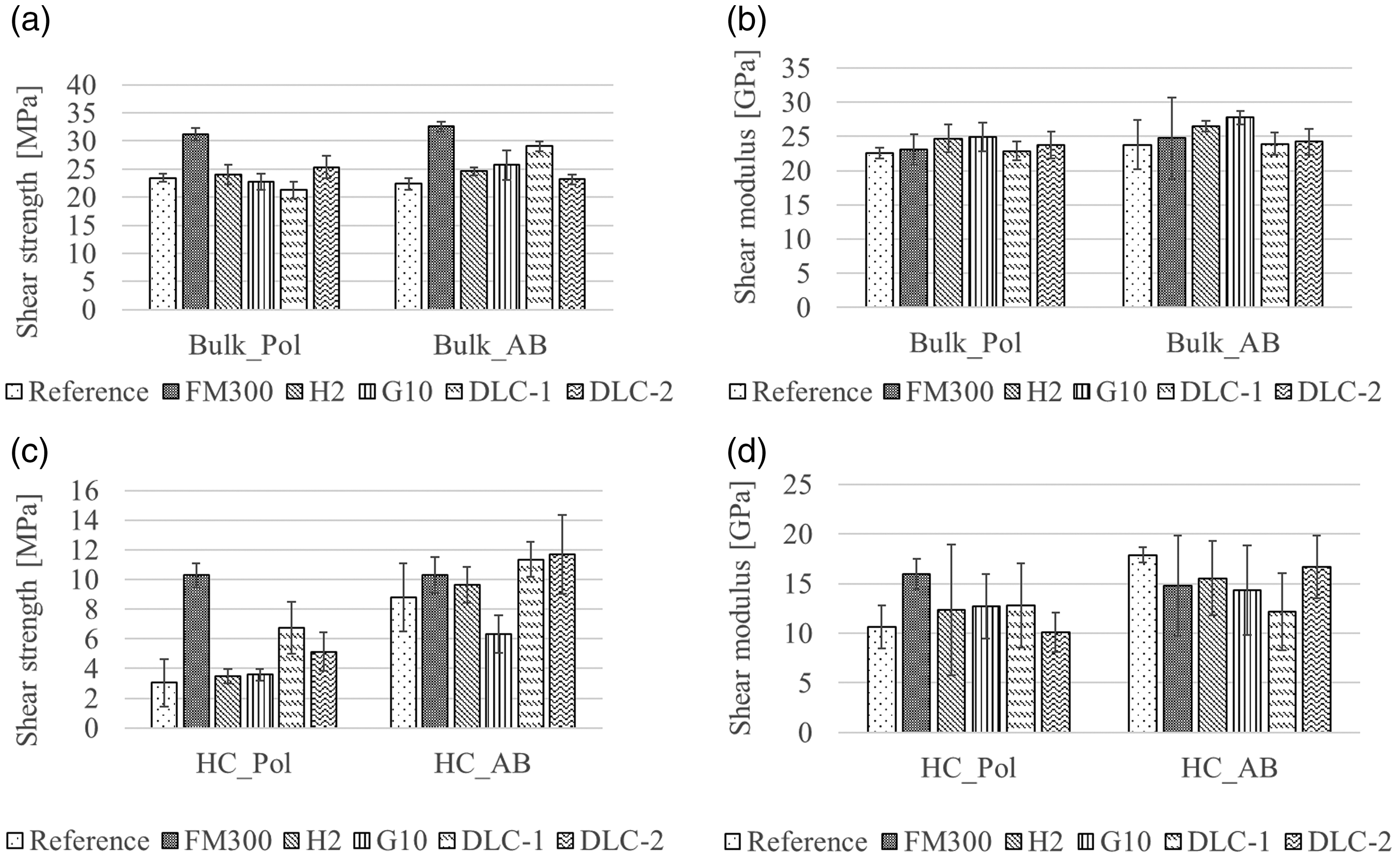
(a) Shear strengths and (b) Shear modulus in case of the polished and as-built honeycomb. (c) Shear strength and (d) Shear modulus of the as-built and polished bulk series.
The good performance of the DLC-1 samples can be attributed to the improved wetting behaviour of the AM surface when coated, as confirmed by the homogenous interface depicted in Figure 7(d). The corresponding fracture surface shows high amounts of epoxy and carbon fiber tow remainders, indicating a mostly cohesive bond failure. The references (Figure 7(a) and (b)) as well as the DLC-2 coated (Figure 7(e)) samples showed considerable imperfections in form of dry spots, where the resin could not completely wet the AlSi10Mg surface. Furthermore, less fiber remainder was detected on the fracture area indicating an adhesive failure mechanism.
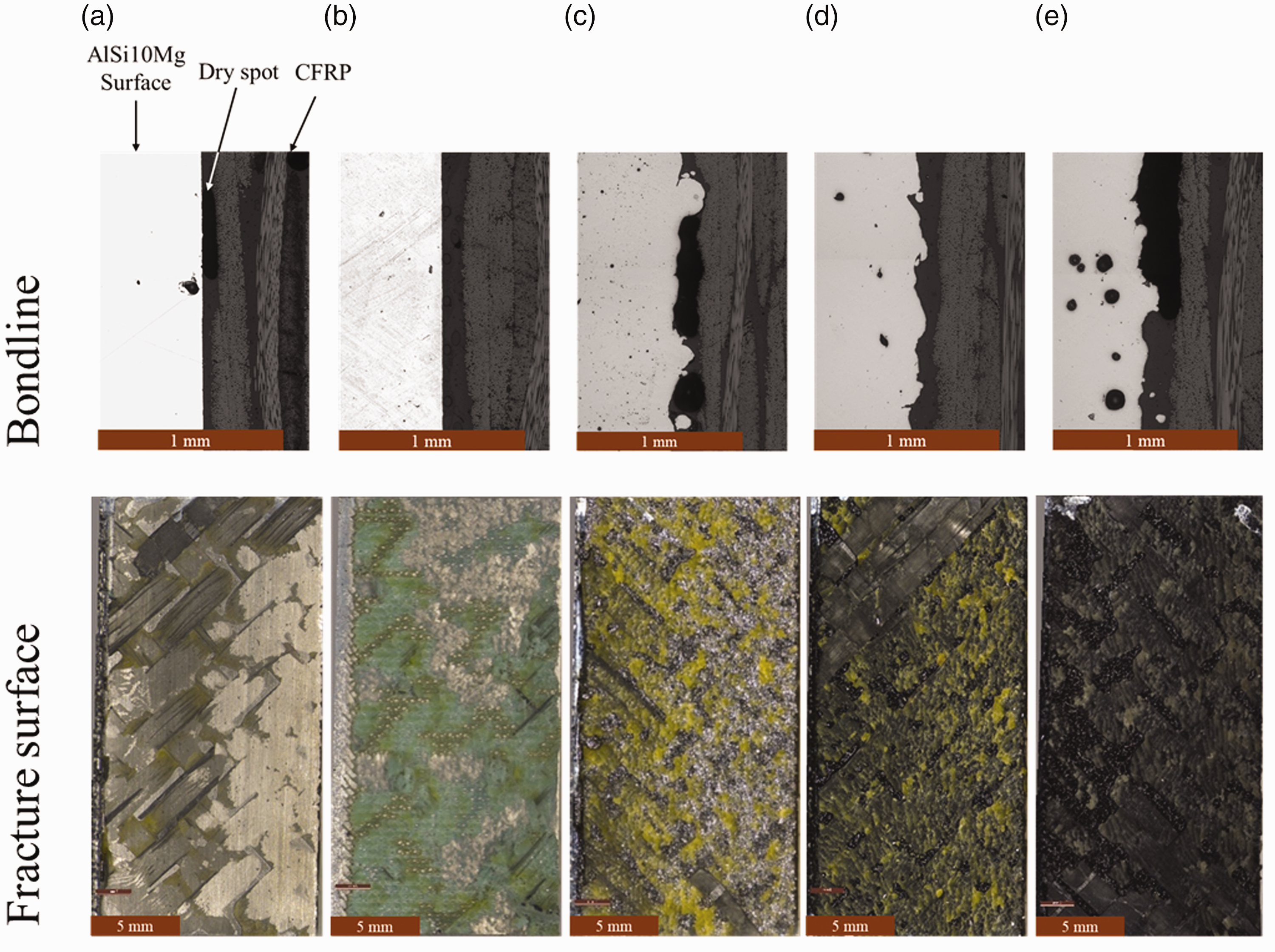
Micrographs of the bondline and fracture surface in case of samples with AM: (a) polished bulk, (b) polished bulk with FM300, (c) as-built bulk, (d) as-built bulk coated with DLC-1 and (e) as-built bulk coated with DLC-2.
Most polished samples failed in a mixed adhesive and cohesive mode, accompanied by delamination of the CFRP adherend, as shown for the reference in Figure 7(a). An exception to this observation was found in case of applying the adhesive layer, which failed mostly cohesively (Figure 7(b)), recognized by the characteristic green adhesive residues on both counterparts. In contrast, as-built bulk DLS samples all showed a brittle fracture mode.
Honeycomb structure
An overview of the shear strengths attained by the structured honeycomb surfaces prepared by different adhesion promoters is given in Figure 6(c). Results show that polishing the adhesion surface rather leads to reduced bond strength (e.g. 8.79 MPa for uncoated and as-built, in contrast to 3.04 MPa for the uncoated polished samples). Surface preparation does not affect the bond strength, when an adhesive film is applied, maintaining a value of 10.3 MPa for both polished and as-built surfaces.
In case of the polished surfaces, the shear strength of the organosilane treated samples lied within the same range as for the polished and uncoated sample. DLC-1 and DLC-2 coatings were able to increase strength up to 11.3 and 11.7 MPa, respectively for as-built adherends. This can be attributed to the pronounced fillets of resin formed around the cell wall (as schematically depicted in Figure 8(a) and observed in Figure 8(b)) due to improved wettability and the associated increase in the bond area. Figure 8(c) shows even larger resin fillets provided by the adhesive film. The cross-sectional view (Figure 8(d)) through a polished honeycomb sample shows that the cell diameter of 3.2 mm was easily bridged by the facesheet (no fibers bending into the cell).
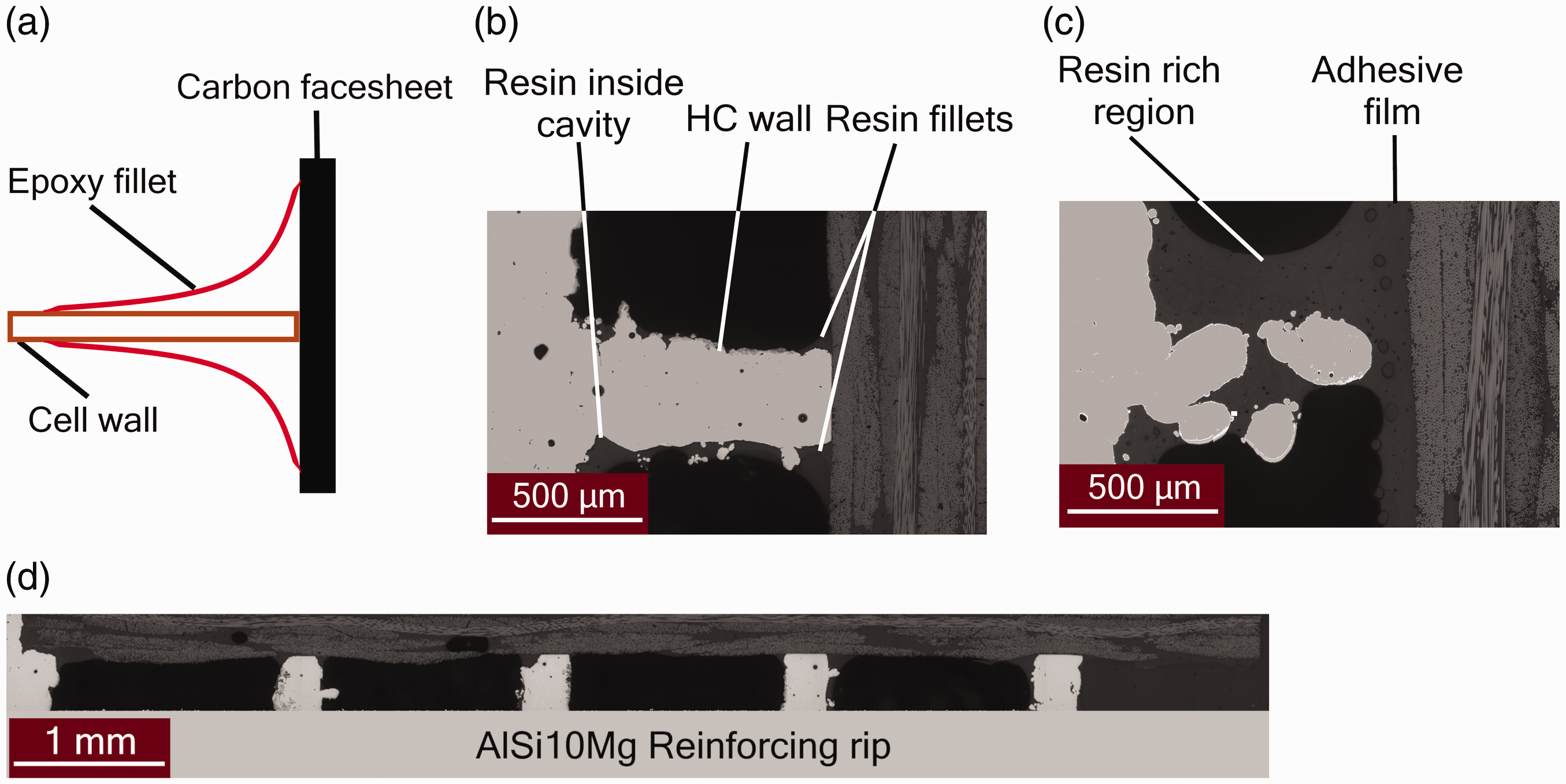
(a) Schematic profile view of a symmetric resin fillet surrounding the cell wall. Cross-sectional micrographs of the honeycomb-CFRP interface for (b) polished honeycomb coated with DLC-1 and (c) polished honeycomb adhered with FM300. (d) Complete cross-sectional view of the bondline of a polished honeycomb DLS sample coated with DLC-1.
The shear moduli, presented in Figure 6(d) can only be considered qualitatively, due to high scattering. Nonetheless, a minor trend for higher shear moduli could be observed for the as-built samples in contrast to the polished ones.
Flexural strength
Conventional Nomex and aluminum honeycomb-based sandwiches usually fail due to core shear. However, all samples under investigation failed due to debonding between the core and the facesheet on the compression-loaded side (Figure 9(a)). This can be attributed to the higher shear strength of the AM AlSi10Mg core structure. The results of the specific flexural strengths are depicted in Figure 9(b).
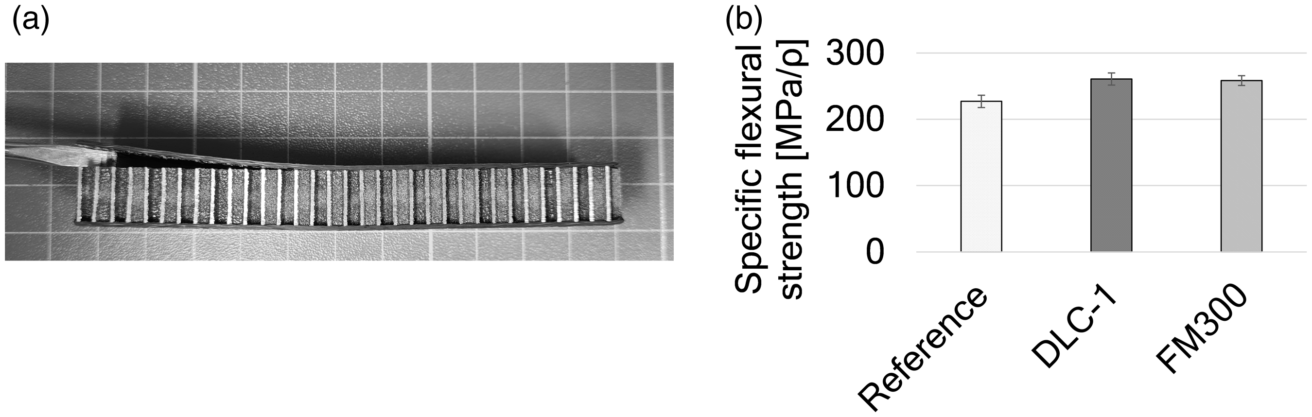
(a) Debonding of facesheet on the compression-loaded side of the sandwich specimen. (b) Specific flexural strength in dependence of the treatment condition.
Both the DLC-1 and FM300 promoted the specific flexural strength by 15% over the uncoated and as-built reference. Interestingly, the DLC-1 coating reaches comparable values to the FM300, which highlights the efficient adhesive properties of the coating without adding supplementary weight. Again, this can be attributed to the pronounced fillet formation.
Conclusions
The DLC-1 coating was found to have the greatest contribution to increasing shear strength, in case of as-built bulk and polished honeycomb core configurations, denoting a 30% increase compared to the as-built bulk reference. Further, the microscopic investigation of the as-built bulk surface coated with DLC-1 revealed minor dry spots at the interface between the coating and the CFRP, in comparison to the reference and the DLC-2 coated samples. This result highlights the importance of adequate wetting when bonding a relatively rough surface.
The greatest impact on the adhesion strength of the honeycomb samples was found to be the surface roughness. The rough surface increases the available bonding area and allows the resin to mechanically interlock with the cell walls. Fillet formation was observed for all investigated honeycomb samples, especially when applying adhesive film. It was observed that in case of polished honeycomb surfaces fillet formation was fostered by the high wetting ability of DLC-1. Under shear loading conventional sandwich materials with a Nomex core fail at shear strengths of 1 ± 0.5 MPa. This is substantially lower than the shear strength of 11.3 ± 1.0 MPa attained in this study by coating as-built honeycomb with DLC-1. This can be attributed to the improved adhesion at the core-facesheet interface and to the thicker cell walls of AM structures (wall thickness of 300 µm for AM; wall thickness of 60 to 80 µm for conventional aluminum, as offered for instance by the company Euro-Composite SA).
The organosilane coatings under consideration did not significantly affect the mechanical performance of the joints. The shear strength of 28 MPa attained in previous work with organoslilane coatings in aluminum-CFRP DLS joint could not be achieved. An incompatibility between the resin and the functional groups in the organosilane is believed to limit adhesion in the here studied coupling agents. This assumption is based on the fact that the measured surface energies (polar and dispersive shares) of the organosilane coatings did not comply with those of the RTM6 resin, resulting in unfavourable wetting capabilities.
In general surface polishing prior to coating was not found to positively affect the overall mechanical performance of the joints. None of the investigated coatings was able to improve adhesion strength over the reference in case of polished surfaces. Hence, it can be concluded that the investigated coatings did not foster chemical bonding with the resin and that improvements were mainly based on mechanical interlocking. An exception hereto was observed in case of applying DLC-1 coating.
Applying the adhesive film FM300 as an intermediate layer between CFRP and metallic adherend promoted an increase in shear strength, reaching a value of 32.58 MPa in case of as-built bulk surfaces, irrespective of the surface roughness. Failure was mostly governed by the load bearing capacity of the adhesive film.
The experimental results presented here show the high potential of additive manufacturing for the fabrication of complex shaped and functionally integrated lightweight metallic structures for in special applications, such as in aerospace or aeronautics. For such cases, additive manufacturing and surface preparation of other alloys (e. g. titanium) are under investigation. Further, additive manufacturing opens the gates for the realization of optimized surface topography for improved bonding with other structures.
Footnotes
Acknowledgements
Special thanks are dedicated to the company Kuhn Beschichtungen GmbH, Germany for coating selected samples by DLC.
Declaration of Conflicting Interests
The author(s) declared no potential conflicts of interest with respect to the research, authorship, and/or publication of this article.
Funding
The author(s) disclosed receipt of the following financial support for the research, authorship, and/or publication of this article: This study was financially supported by the Bavarian Research Foundation within the framework of the grant number AZ-1335–18. The authors acknowledge the support of the Department of Components and Processes of the Fraunhofer Institute for Casting, Composite and Processing Technology (IGCV) for providing the metallic components fabricated by the LBM process.