
Abstract
We use the reduced relaxed micromorphic model (RRMM) to capture the effective “bulk” dynamical response of finite-size metamaterial specimens made out of a Labyrinthine unit cell. We show that for small finite-size specimens, boundary effects can play a major role, so that the RRMM needs an enrichment to capture the metamaterial’s bulk response, as well as the boundary effects. A benchmark test is introduced to show that different metamaterial/ homogeneous material interfaces can drive completely different responses even if the bulk metamaterial remains the same. We show with no remaining doubts that the concept of “interface forces” must necessarily be introduced if one wants to model finite-size metamaterials in a homogenized framework.
Keywords
1. Introduction
In the last decades, mechanical metamaterials have gathered significant attention, owing to their exotic capabilities regarding mechanical wave propagation. Metamaterials are materials with a microstructure specifically tailored to grant them unique properties, such as a negative Poisson’s ratio [1–3], negative refraction [4–9], chiral effects [10–14], band gaps [15–18], cloaking [19–22], and others [23–29].
The potential applications of mechanical metamaterials are promising, specifically in regard to acoustic isolation and passive vibration control. While significant progress has been made in understanding, designing, manufacturing, and modeling such materials, open problems still exist. One of the key problems is modeling metamaterials at large scales, which is crucial for real-world engineering applications. This problem implies the need for a homogenized description of metamaterials. The importance of micromorphic models for modeling metamaterials and heterogeneous media though a homogenized description has been acknowledged through the development of homogenization techniques in the quasi-static regime [30–50] as well as, more recently, in the dynamic regime [51–64]. In recent papers [65–72], we have shown that the reduced relaxed micromorphic model (RRMM) performs well in describing the response of infinite-size metamaterials and also for some simple finite-size problems.
We have shown in Demetriou et al. [73] that the RRMM captured adequately the response of two finite-size metamaterials constructed from two different tetragonal unit cell “cuts” except close to the boundary, where “cut”-related boundary effects took place. In the same paper, we argued that enriching the boundary conditions of the model would be a possible way to capture these boundary effects. This has been proven in Ramirez et al. [74], where the enrichment of boundary conditions was introduced, through the new concept of interface forces, where the authors showed that the different boundary of a metamaterial (direct consequence of the choice of unit cell “cut”) must lead to the activation of a different surface force in the homogenized framework, if one wants to capture boundary effects using an effective “homogenized” model. This method, inspired by the elastic interface model, is the first application of an interface model on macroscopic boundaries that addresses and solves the problem of boundary effects arising in metamaterials of finite size.
In this work, we study the response of four finite-size specimens constructed from four different “cuts.” We capture their behavior using the RRMM coupled with the new concept of interface forces at metamaterial’s boundaries. We show what ansatz these forces should follow, for the particular test under consideration, and how this ansatz scales when the magnitude of the excitation force is scaled.
In particular:
In section 2, we stress the importance of the choice of the metamaterial’s unit cell “cut” for finite-size applications and we introduce the four “cuts” that will be used in the benchmark tests in this work.
In section 3, the RRMM is introduced, which is the enriched model we use in this work to model metamaterial specimens in a homogenized framework. We present the equilibrium equations and boundary conditions derived using variational principles, and we recall the parameter identification procedure used to fit the parameters of the RRMM for the specific metamaterial.
In section 4, we explain in detail both the full microstructured simulations and those implemented by modeling the metamaterial with the RRMM coupled with interface forces and show explicitly the boundaries where the activation of an interface/surface force can occur.
In section 5, we introduce the method of interface forces in a reduced relaxed micromorphic (RRM) framework, stressing the fact that it is essentially the first application of an interface model on macroscopic metamaterial interfaces and also (to our knowledge) the first attempt to tackle the problem of modeling boundary effects in metamaterials using a homogenized model, where boundary effects arise from the choice of unit cell “cut” in the finite-size metamaterial.
In section 6, we introduce a specific ansatz for our interface forces and show that this ansatz holds for the frequencies under consideration except for a small frequency range in which the corresponding wavelengths are comparable to the specimen’s size. We show the results of our simulations using vanishing and non-vanishing interface forces, for the RRMM and for a Cauchy material which is the long-wavelength limit of the RRMM.
In section 7, we present the transmissibility plot for the four finite-sized metamaterials under consideration to stress once again the importance of the choice of unit cell “cut” and we show a particular case where a region of low transmissibilty appears outside of a band-gap, owing to the finite size and the choice of unit cell “cut.” Lastly, we present some independent tests with increasingly bigger metamaterial specimens using the same four unit cell “cuts,” in order to stress that the infinite metamaterial assumption of Bloch–Floquet analysis has limits. We explain that this assumption can only hold when boundary effects can be neglected for any possible unit cell “cut” for the specific test under consideration.
2. Importance of the choice of the metamaterial’s unit cell “cut” for finite-sized problems
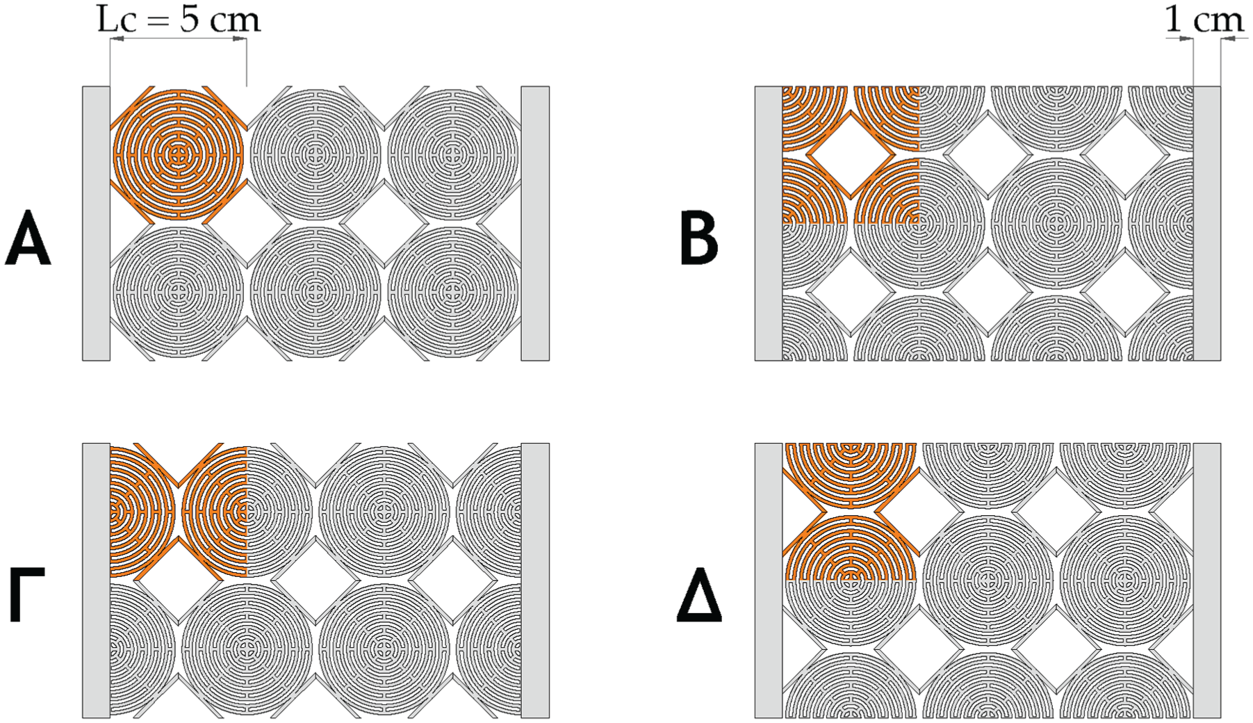
We start with presenting the geometrical and material characteristics of the metamaterial under study and whose infinite-size dynamical response will be described through the RRMM. The considered metamaterial is built via the periodic repetition in space of the Labyrinthine unit cell presented in Figure 1.
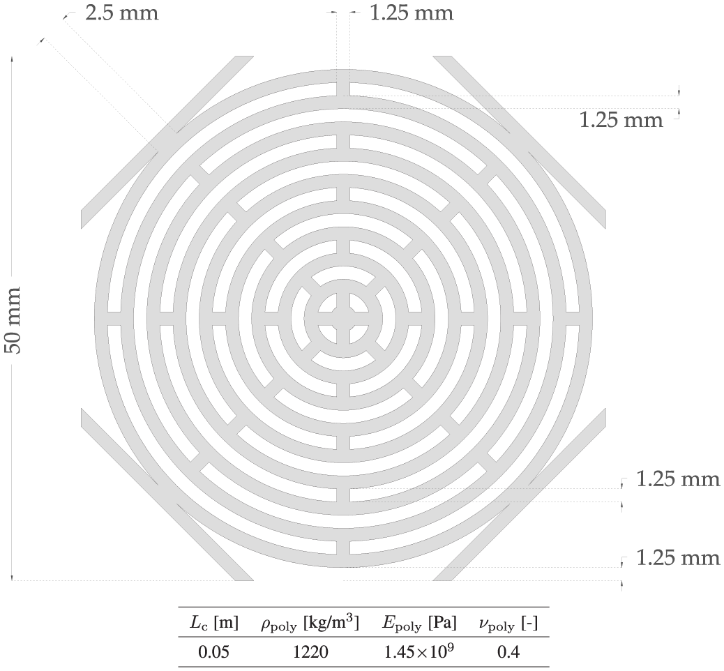
Unit cell and material properties of the metamaterial studied in this paper. The base material is polyethylene currently used in 3D printing.
This specific unit cell presents wide band-gap behavior in the acoustic range and has already been successfully tested in experimental campaigns [75]. An effective RRM modeling of finite-size metamaterials stemming from this unit cell is particularly important in view of upscaling towards larger scales. Indeed, mastering the homogenized response of this metamaterial through the RRMM at small scales will allow the design of larger-scale structures as it would not be otherwise possible via fully detailed microstructured simulations.
Metamaterial specimens based on the unit cell given in Figure 1 can be manufactured using 3D printing techniques [75]. All the geometrical and material properties needed to characterize the considered unit cell are given in Figure 1.
The periodic repetition in space of the unit cell of Figure 1 gives rise to the infinite-size metamaterial depicted in Figure 2.
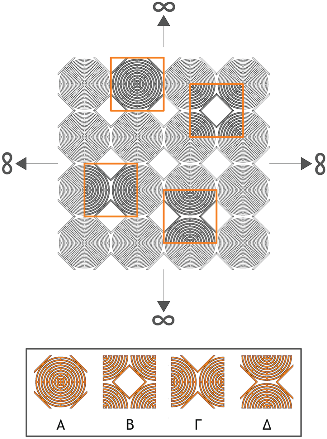
Infinite-size periodic metamaterial (top) and the four unit-cell cuts of the labyrinthine metamaterial used in our simulations (bottom). Cells A and B are of tetragonal symmetry and cells Γ and Δ are of orthotropic symmetry.
There is one important point to make: Although we build our infinite metamaterial from the unit cell described in Figure 1, the base unit cell is not inclusive. Instead, the same infinite metamaterial can be equivalently obtained by the periodic repetition in space of any of the unit-cell “cuts” A, B, Γ, and Δ, as shown in Figure 2, as well as of infinitely many other “cuts” (some of which are less symmetric) which are not shown in Figure 2. While the choice of the unit-cell’s “cut” does not play a role for retrieving the resulting infinite-sized metamaterial and corresponding bulk behavior (Bloch-Floquet analysis), it has a huge effect as soon as metamaterials of finite size, i.e., with boundaries, are considered.
It has been shown in Hermann et al. [75] that the choice of the unit-cell’s cut can play a major role as soon as small finite-sized metamaterial specimens are considered. The impact of such boundary effects on finite-sized metamaterials’ structures has also been validated experimentally [75].
It is the ambition of this paper to enrich the RRMM with suitable boundary and interface conditions to show that this model can be safely used also when boundary effects cannot be neglected due to the finite size of the considered structure. The use and calibration of the reduced relaxed micromorphic model on small finite-sized metamaterials’ specimens is a necessary step if one wants to reach the major challenge of designing large-scale albeit finite-sized metamaterial’s structures. This necessity arises from the fact that an enriched homogeneous model cannot account for different shaped boundaries on its own, i.e., it cannot distinguish between the different unit-cell’s “cut” of the finite-sized metamaterial. As we will show in detail in the remainder of this paper, to reach this goal, the concept of “macroscopic elastic interface” and of “interface forces” must be introduced in the RRM framework. Such concepts have been introduced for the first time in [74] to describe, through the RRMM, the boundary effects arising in finite-sized metamaterial’s specimens based on a different unit cell with respect to the one studied in the present paper. However, due to the novelty of the introduced concepts, a thorough study is needed to address all the challenges associated with this new idea.
In this paper, we will unveil which type of interface forces are needed in the reduced relaxed micromorphic framework to reproduce the dynamic behavior of four types of small metamaterials’ specimens which are obtained by differently “cutting” the base unit cell of Figure 2 which, in turn, implies that the macroscopic boundaries of the considered specimens are of different types (for more details, see section 4). We will show that if one wants to catch the different response of these four specimens (predominantly driven by boundary effects) in a reduced relaxed micromorphic framework, then the concept of macroscopic interface forces must necessarily be introduced.
Moreover, we will start unveiling, for the first time, some general properties that these macroscopic interface forces should possess, such as scaling with respect to the intensity of the externally applied load.
3. The relaxed micromorphic model: a reduced version for dynamics
We introduce here the equilibrium equations, the associated boundary conditions, and the constitutive relations for a reduced version of the relaxed micromorphic model for dynamic applications 1 2 . The equilibrium equations and the boundary conditions are derived with a variational approach thanks to the associated Lagrangian:

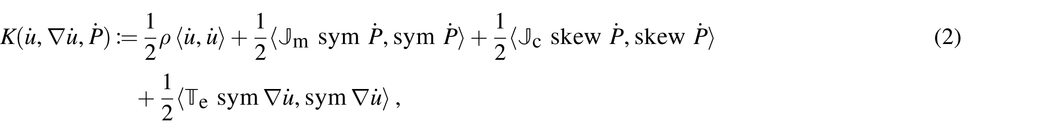
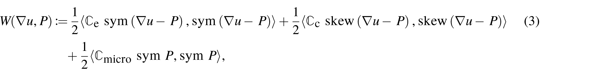
where K and W are the kinetic and strain energy, respectively, defined as:
where ⟨⋅,⋅⟩ denote the scalar product, the dot represents a derivative with respect to time,
In particular, we report here the structure of the microinertia and the elasticity tensors for the tetragonal class of symmetry and in Voigt notation 3 , where only the parameters involved under the plane-strain hypothesis are explicitly presented. Thereby, the symbol ⋆ indicates that the specific entry do not intervene under the plane-strain hypothesis. The class of symmetry has been chosen accordingly with the symmetry of the unit cell presented in Figure 1, under the assumption that the same class of symmetry applies both at the micro- and the macro-scale:
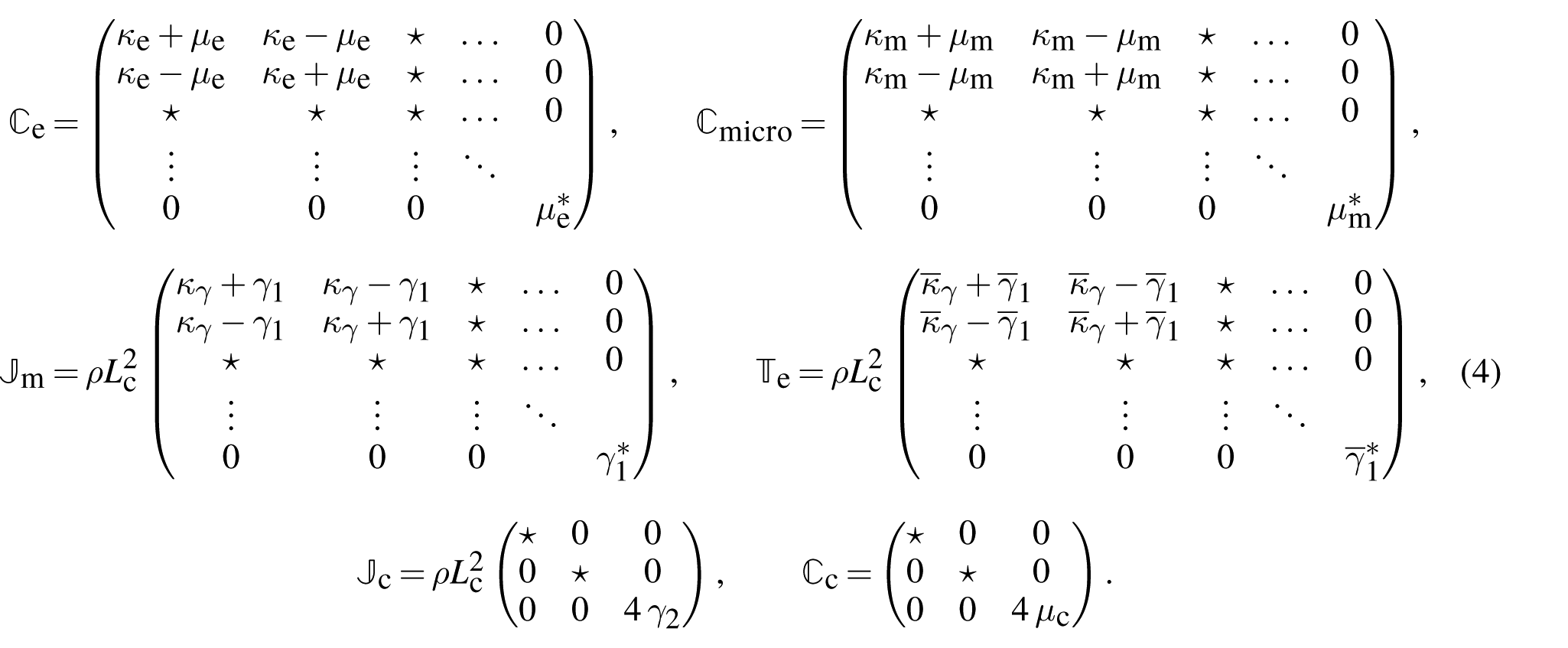
Only the in-plane components are reported since these are the only ones that play a role in the plane-strain simulations presented in the following sections. The choice of this particular class of symmetry is related to the fact that a macroscopic block of the metamaterial considered in this paper clearly shows tetragonal symmetry (see macroscopic metamaterial block in Figure 2). The action functional

and its first variation

with


as well as the Neumann boundary conditions:

where

where κ and μ are the classical bulk and shear moduli, respectively,
3.1. Identification of the RRMM parameters via dispersion curve fitting
In this section, we briefly recall the RRM parameters’ identification procedure that is done by the means of fitting the dispersion curves as obtained via classical Bloch–Floquet analysis. The dispersion curves (Figure 6) of the microstructured material can be obtained by employing a standard Bloch–Floquet analysis on any unit cell of the four in Figure 2. In our case, the employment of standard Bloch–Floquet analysis is done using Comsol Multiphysics®. All four unit cells give rise to the same dispersion curves since a Bloch–Floquet analysis employs periodic boundary conditions, thus mimicking an infinite domain. All four unit cells shown in Figure 2 are equivalent in the sense that they give rise to the same infinite metamaterial.
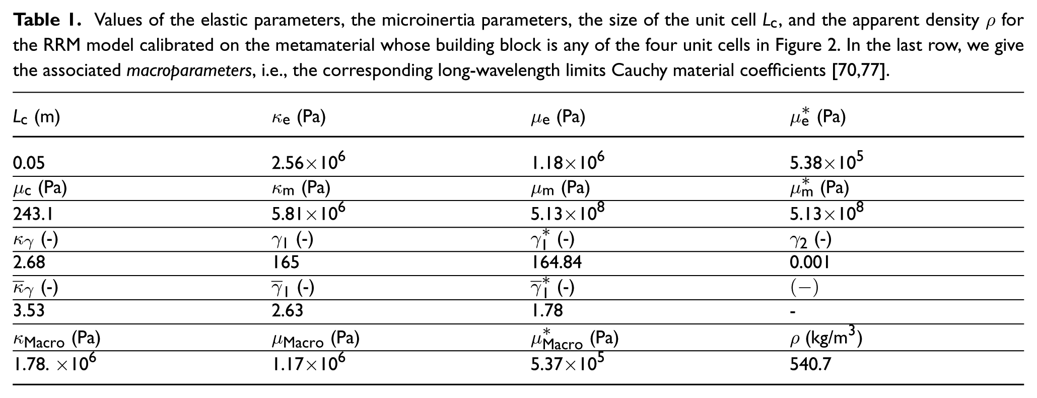
In the next step, the data from Bloch–Floquet analysis (performed on any of the four unit cell cuts in Figure 2 to obtain the dispersion curves) is used to fit the bulk material parameters of the RRMM. Thus, these parameters correspond to the infinite metamaterial in Figure 2. To perform the RRM fitting, dispersion curves for the RRMM are obtained analytically by finding the roots of the determinant of the acoustic tensor associated with the homogeneous equilibrium equations (6) under a plane-wave ansatz (for more details, see Voss et al. [68]). The number of independent parameters in the RRMM is 15: 8 of them can be analytically evaluated or (analytically reduced by the other remaining parameters (11) using the expression of the cutoffs and long-wavelength limit 4 , while the remaining free parameters are obtained with a quadratic error minimization procedure so that the dispersion curves issued via the RRMM are the closest possible to those issued via Bloch–Floquet analysis (see Figure 6). The parameters with an analytical expression are [76]:
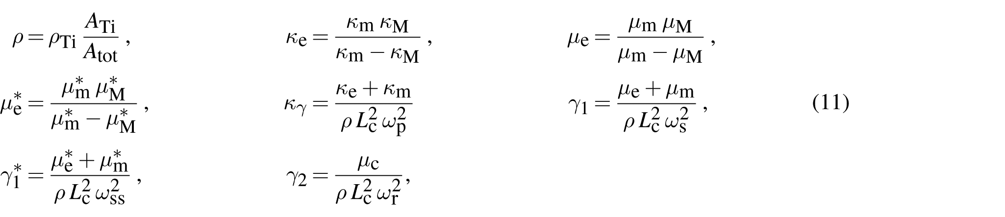
where
As already remarked, the remaining seven free parameters
Values of the elastic parameters, the microinertia parameters, the size of the unit cell
4. Full-microstructured and reduced-relaxed-micromorphic finite element simulations for selected benchmark tests
In this section, we present the four benchmark tests that have been chosen to unveil the importance of the concept of interface forces for the homogenized modeling of finite-size metamaterials. We present the setting-up of the numerical simulations on a finite-size metamaterial both with a microstructured Cauchy model (full detail of the unit-cell microstructure is coded in the numerical simulations) and the RRMM (a homogeneous domain is used in the numerical simulations in which the constitutive laws are those of the reduced relaxed micromorphic model and are eventually enriched with the concept of interface forces). For both the microstructured and the micromorphic simulations, we will take advantage of the symmetry of the problem, allowing us to reduce the computational time by simulating half of the structure while applying the appropriate symmetry conditions on the cut boundaries.
4.1. Full-microstructured simulations’ set-up
The full-microstructured simulations take into account the detailed specimen’s geometry, and the metamaterial’s behavior is simply given by classical Cauchy elasticity. This process is typically computationally expensive due to the complex interior geometry of larger specimens, but it is manageable here because of the low number of unit cells used. All the 2D simulations presented here have been performed under a plane-strain assumption and with a time-harmonic ansatz: this means that instead of solving a time-dependent problem, the corresponding eigenvalue problem is numerically solved for each frequency value considered. The four microstructured materials presented in this work have been built as a regular grid of finite-size (
where σ is the classical Cauchy stress tensor given in equation (10), n is the outward unit normal to the interface, and the expression of the externally applied force per unit area is:
The four 3×2 specimens, each constructed from one of the four unit-cell cuts of Figure 2. The specimens are embedded between two Cauchy plates made out of the same material (polyethylene). For simplicity, we keep the nomenclature
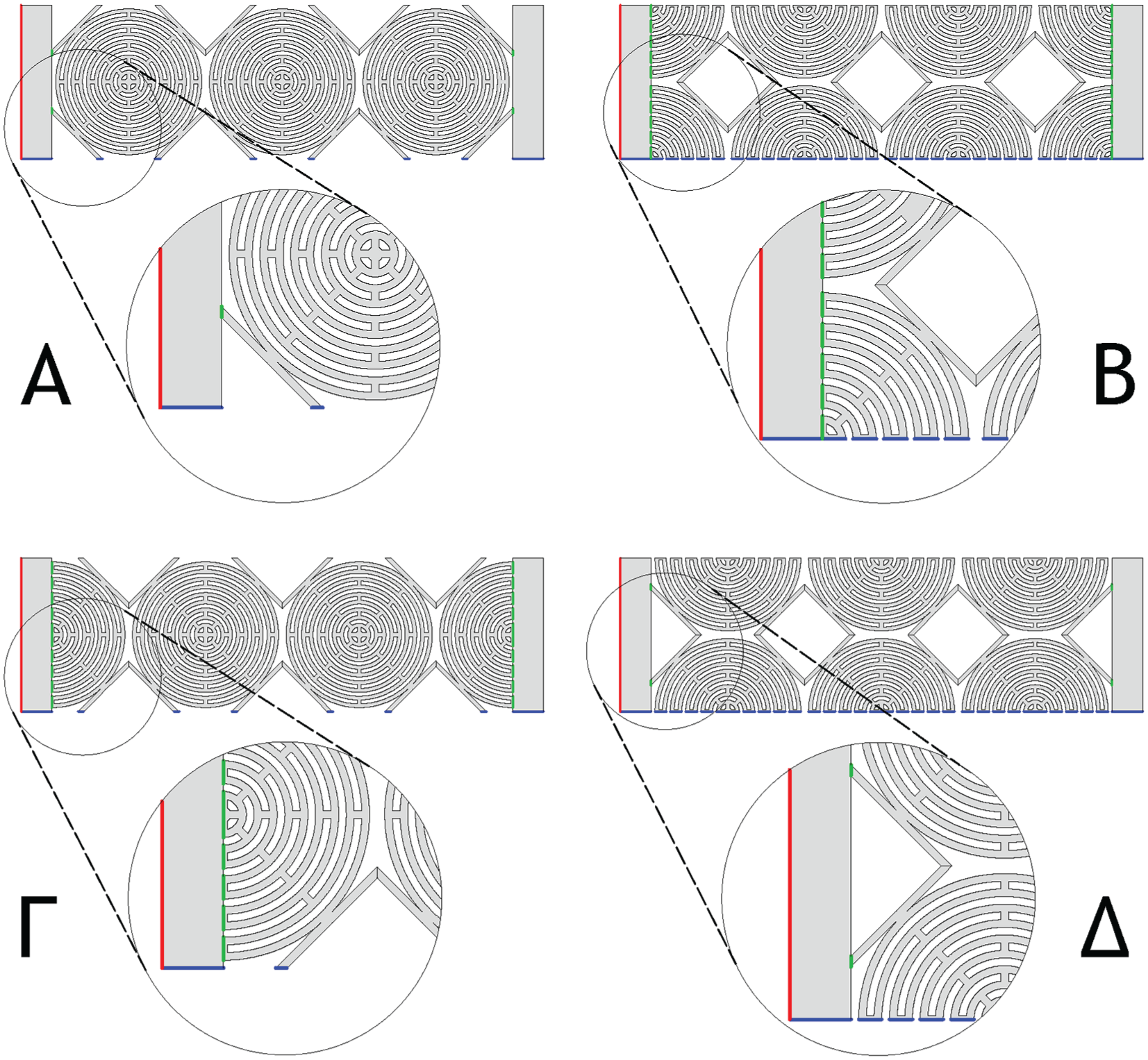
Schematic view of the geometry and the labeling of the boundaries and interfaces for the four microstructured specimens: A (top left), B (top right), Γ (bottom left), and Δ (bottom right).
4.2. Reduced-relaxed-micromorphic simulations set-up
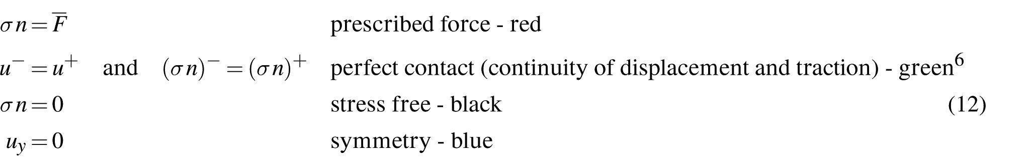
The microstructured metamaterial is here modeled with the RRMM, which is characterized by the material parameters in Table 1. This means that the microstructured (heterogeneous) domains in Figure 3 are replaced with a homogeneous domain of the same size (see Figure 5) whose constitutive behavior is set to be that of an RRM continuum (i.e., governing equations (6) hold in this bulk domain with the kinematic variables u and P). In addition, the following boundary and interface conditions have been enforced (see Figure 5 for the definition of the different interfaces):

where the Cauchy stress σ is given in equation (10), the enriched stress tensors
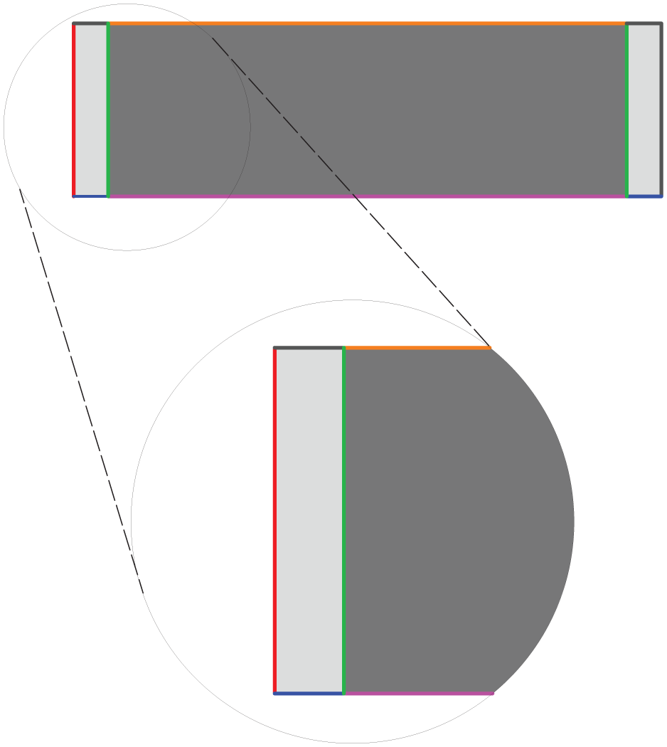
Schematic view of the geometry and the labeling of the boundaries and interfaces for the equivalent reduced relaxed micromorphic modeling of the considered metamaterial’s specimens: reduced relaxed micromorphic governing equations (6) are enforced in the darker gray bulk region, while classical isotropic Cauchy governing equations
5. Material interfaces: from microscopic towards macroscopic interfaces
In the context of mechanical problems, various interface models can be categorized depending on the quantities that may suffer a jump across the interface itself:
These various interface models are well known in the literature and widely used in the context of periodic homogenization of heterogeneous media [78]. This means that, usually, the discontinuity of the material properties is considered at the scale of the unit cell (e.g., the microscopic interface that separates two different materials inside the unit cell). These macroscopic material interfaces are then taken into account in the homogenization procedure to show that the obtained homogenized (infinite-size) continuum exhibits different macroscopic bulk properties if one considers different interface properties at the microscopic level. For the latter, a finite thickness interface can be approximated by a zero-thickness interface for practical purposes, when its thickness is relatively small compared to other length scales [85].
The viewpoint adopted in the present paper is quite different, since we are stating that, when considering finite-size (macroscopic) metamaterials’ specimens, also the macroscopic specimen’s boundaries should be treated as material interfaces carrying their own material properties. In particular, the macroscopic interfaces considered in this paper will be treated as (macroscopic) elastic interfaces across which the displacement field remains continuous, while the traction may suffer a jump. Indeed, this choice is justified by the type of metamaterials that we want to describe through our homogenized model. The macroscopic interfaces occurring in our problem are highlighted in Figure 5 with a green (RRM/Cauchy interface) or an orange (free RRM interface) color. When considering the green interface connecting the RRM continuum to the Cauchy plate, we want that this interface models the transition from the metamaterial in Figure 4 to the Cauchy continuum. On one hand, given the type of connections shown in Figure 4, under the hypothesis that there are no defects in the solid-solid connections between the metamaterial and the Cauchy plate, it is natural to consider that at the macroscopic (homogenized) level one should impose continuity of the macroscopic displacement across the green line in Figure 5. On the other hand, it is also evident that if one would also impose the continuity of traction across the green line in Figure 5, then the RRMM would not be able to discriminate between the four different cases presented in Figure 4, since the homogenized solution imposing
It becomes thus clear that, in order to discriminate between the four different cases in Figure 4, the homogenized counterpart must account for the possibility of a jump of the traction along the green lines. Across these lines, the last equations in equation (13) should then be modified to:

where

where
Up to this day, interface models have been used in the modeling of a number of phenomena such as adhesives and their fracture [86–88], crack growth [89–91], damage [92–94], surface effects between matrix and inclusion in nanomaterials and composites [78,95], and grain boundary microcracking [96–98]. To our knowledge, as has been extensively explained in Ramirez et al. [74], no application exists for the modeling of macroscopic (homogenized) boundaries in the area of metamaterials and metastructures, which is where we want to address some of the open challenges in the present paper. We stress that interface methods have been used to model size effects in nanomaterials [78] or composites with fibers [99] but only to model the interphase between the matrix and the inclusion in the RVE of the composite and thus, as stated before, only at the microscopic level.
6. Macroscopic elastic interfaces in the homogenized modeling of mechanical metamaterials through the RRMM: a case study
In the context of modeling metamaterials as homogenized media, the concept of considering macroscopic interface forces is practically disregarded in the literature. This concept of macroscopic interface force has been introduced in Ramirez et al. [74] for the first time. However, given the novelty of this concept, many challenges remain open and must be addressed with targeted case studies so as to unveil the specific properties that such interface forces should have and to draw some general conclusions. It is the ambition of this paper to thoroughly study the properties of interface forces in the context of RRM elasticity for the case study presented in Figures 4 and 5. As we have stated in section 5, introducing the concept of interface forces at macroscopic interfaces separating a homogenized RRM continuum from another continuum is an absolute priority if one wants to extend the use of homogenized models from a purely infinite-size framework to the study of more realistic “finite-size” structures. In this section, we will describe in more detail the specific form that such interface forces should take so that the RRMM can be safely used to describe the four different metamaterial’s specimens of Figure 4 which are all issued from the same infinite metamaterial which is differently “cut” at the corresponding macroscopic interfaces.
For the case study of this paper, introduced in Figure 4 (Figure 5 for its RRM counterpart), we consider the following traction jump conditions across the green lines in Figure 5 separating the RRM continuum from the Cauchy plates:

where
We thus note that here the jump of the traction at the interface takes the simple form of a linear function of the RRM traction. However, depending on the complexity of the problem (e.g., more complex loading conditions or different geometries of the macroscopic specimens), this assumption could change and the jump of traction could be allowed to take more complex forms, e.g., α and β being functions of the x or
6.1. RRMM with and without interface forces vs. microstructured and long-wavelength limit Cauchy simulations
In this section, we show the importance of the concept of interface forces when a homogenized model like the RRMM has to be used for the modeling of finite-sized metamaterials’ structures.
To this aim, we consider the comparison between the RRM simulations and the microstructured ones for the A, B, Γ, and Δ “cuts” of different frequencies. When the solution of the RRMM does not match the microstructured solution, we calibrate the corresponding interface forces arising at the interfaces between the RRM domain (corresponding to the metamaterial) and the Cauchy plates (see equation (19)), until the RRM solution matches the microstructured one. We also provide a comparison with a simulation in which the metamaterial domain is modeled through a homogeneous Cauchy continuum which is the long-wavelength limit of the RRMM. In this way, we are able to clearly unveil the advantages brought by the RRM setting. The frequencies chosen are reported in Figure 6 with reference to the dispersion curves.
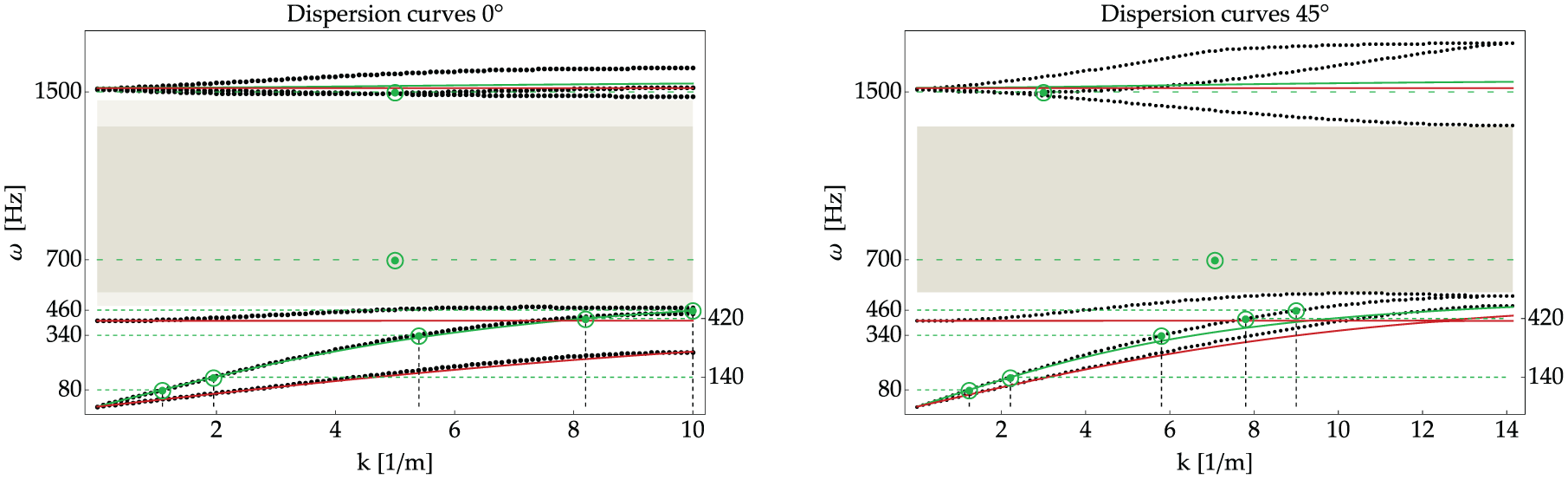
Dispersion curves for
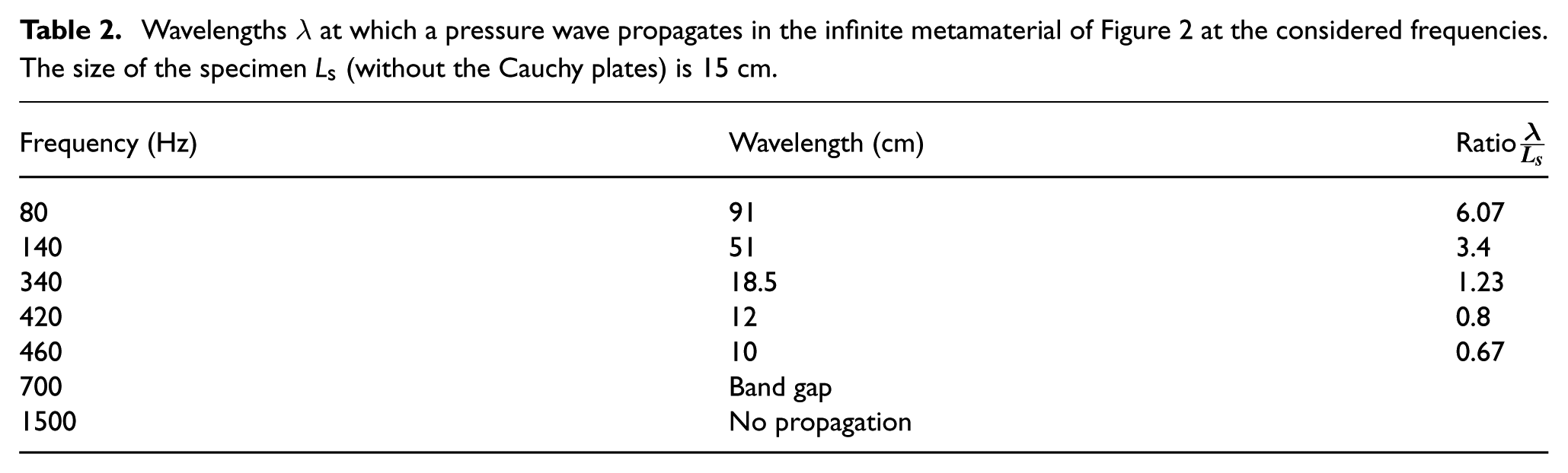
The wavelength for which a wave propagates inside the metamaterial at the considered frequencies is summarized in Table 2.
Wavelengths λ at which a pressure wave propagates in the infinite metamaterial of Figure 2 at the considered frequencies. The size of the specimen
The values of the coefficients
In the following, we also look at the tractions on the Cauchy/RRM interfaces, that could potentially be used as an alternative method to calculate coefficients
Regarding the size of the mesh used in each simulation, we indicate the following: for the cases of modeling the metamaterial using the full microstructure, the mesh of the metastructure (homogeneous Cauchy plates and microstructured metamaterial) was composed of approximately (we have four different versions, one for each cut) 46,700 triangular quintic Lagrange elements and for the case of modeling the metamaterial using a homogeneous model (either the RRMM or the macro-Cauchy), the mesh was composed of 560 triangular quadratic Lagrange elements. All meshes are the result of individual mesh convergence studies using the adaptive mesh refinement node of Comsol Multiphysics ®.
6.1.1. Frequency: 80 Hz
We start analyzing the homogenized Cauchy and RRM simulations and the corresponding comparison to the microstructured ones for the frequency of 80 Hz. This frequency is relatively low and corresponds to a macro-Cauchy-like non-dispersive behavior (see the first point in Figure 6).
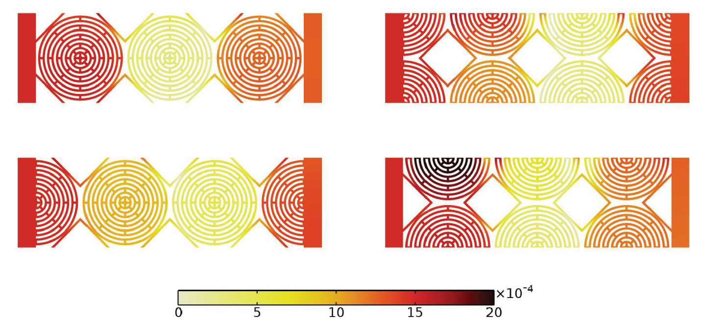
Figure 7 shows that at the frequency of 80 Hz, the RRM solution is almost coinciding with the long-wavelength limit Cauchy solution. We did not include the other unit-cell cuts as there were already in perfect agreement without the need of interface forces. This is related to the fact that the behavior of the dispersion curves is still linear at the considered lower frequency (see Figure 6). However, it is evident that, even at this lower frequency, boundary effects may play a non-negligible role. Indeed, while for the “cuts” A, Δ, and Γ, there is no need to introduce non-vanishing interface forces, and “cut” B needs a non-vanishing interface force to recover the correct solution (see Figure 7). This might be related to the fact that “cut” Γ provides a better solid/solid connection between the metamaterial and the Cauchy plates, so that the applied load is better transmitted through the metamaterial’s specimen. This enhanced boundary-driven transmission can be recovered in the RRM setting through suitable non-vanishing interface forces. However, also for the B case for which interface forces are necessary to recover the correct solution, it can be recognized that the correction brought by triggering
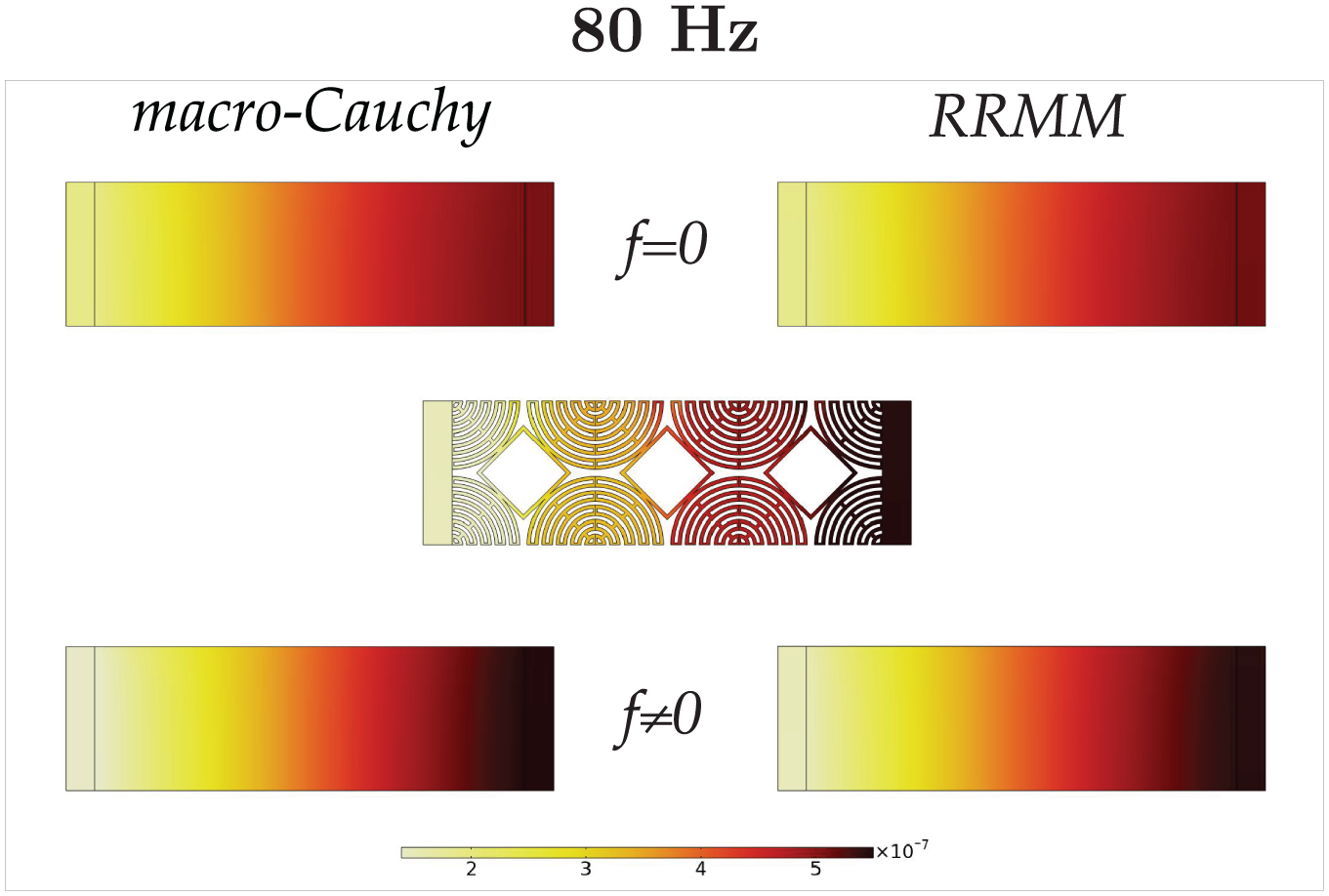
Comparison of the displacement field of the metamaterial specimen B with the macro-Cauchy and the RRMM when
We have seen that at the considered frequency of 80 Hz, both the RRMM and the macro-Cauchy model give good results when suitable interface forces are introduced. This can also be seen when looking at the tractions that arise at the Cauchy-plates/metamaterial interfaces, as shown in Figure 8.
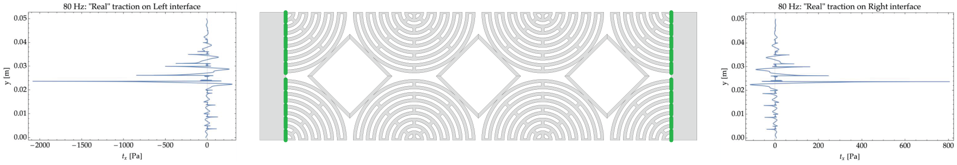
Sketch of the tractions on the Cauchy side of the Cauchy plate/metamaterial interfaces at 80 Hz. The two plots on the two sides of the specimen represent the traction fields on the Cauchy-plate sides along the green lines highlighted in the picture. Similar patters can be observed for all other “cuts” and for other frequencies.
Figure 8 shows the microstructured tractions arising at the Cauchy-plates/metamaterial interfaces (on the Cauchy side), for “cut” B. Completely analogous considerations are valid for all other “cuts.” As a first rough measure, we can compute the “mean” value of this traction 11 and compare it to the corresponding RRM and macro-Cauchy tractions. This comparison is shown in Figure 9, where we can see that there is practically no difference between the RRM and macro-Cauchy tractions both on the left and right interfaces.
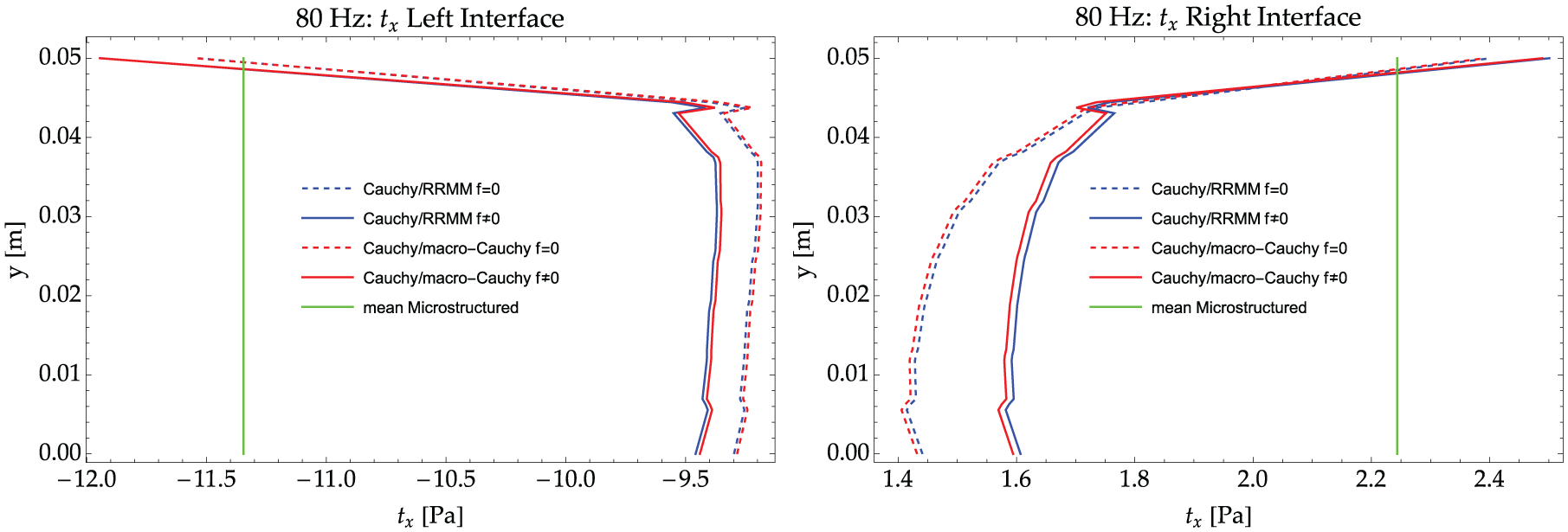
Tractions on the Cauchy side of the Cauchy plate/metamaterial interfaces (left and right) for the RRMM and for the macro-Cauchy when
It can also be inferred that the homogenized (both RRMM and macro-Cauchy) tractions become “closer” to the mean traction calculated starting from the microstructured solution as soon as “interface” forces are triggered. This is a good indication that the homogenized framework including the concept of interface forces is a mandatory step if homogenized models have to be used for finite-size metamaterials modeling. However, we can see that the homogenized (both RRMM and macro-Cauchy) traction does not exactly coincide with the “mean” of the microstructured traction which has been evaluated for comparison. This is due to the fact that the “averaging” of the interface microstructured traction (the one shown in Figure 8) is an operation whose exact definition is an open challenge in the homogenization community. Practically, no work exists which try to incorporate the effect of microscopic heterogeneous boundaries into the existing homogenization procedures. Given the complexity of the considered metamaterials and interfaces, as well as the simplifying hypotheses always present in all upscaling techniques, a rigorous definition of such average interface microstructured tractions could be impossible to be fully achieved.
Our approach, being purely macroscopical, refrains from calculating microscopic averages, but shows which form should take the introduced macroscopic interface forces to bring the homogenized solution close to the microstructured one.
While Figure 9 shows the x-component of the tractions at the Cauchy-plate/metamaterial interface, completely analogous conclusions hold for the y-components, when they are non-vanishing. We do not present graphics of the y-component of the tractions for the sake of compactness.
6.1.2. Frequency: 140 Hz
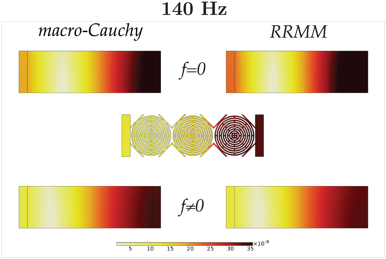
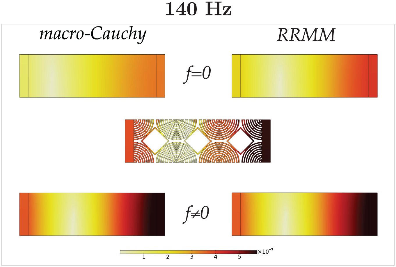
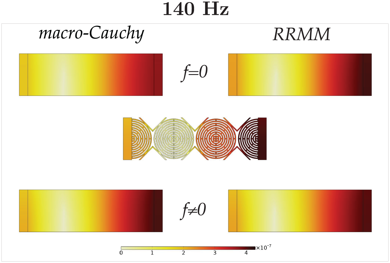
We continue analyzing the homogenized Cauchy and RRM simulations and the corresponding comparison to the microstructured ones for the frequency of 140 Hz. This frequency is relatively low and still corresponds to a macro-Cauchy-like non-dispersive behavior (see the second point in Figure 6).
Figures 10–13 show that at the frequency of 140 Hz both the RRM and the long-wavelength limit (macro-Cauchy) model can recover well the microstructured solution as far as suitable interface forces to discriminate between the four different cuts are calibrated. Indeed, boundary effects are clearly more important here than for the frequency of 80 Hz, since the solution is very different for the four considered cuts, while this strong difference between the different cuts was not present at lower frequencies. It is clear that at this higher frequency, the wavelength decreases to an extent that the different connections between the Cauchy plate and the metamaterial start to macroscopically affect the traveling wave. This means that interface effects are more important than the bulk behavior at the considered frequency and specimen’s size. This must be necessarily accounted for via the introduction of suitable interface forces when considering the homogenized modeling of the considered benchmark test.
Comparison of the displacement field of the metamaterial specimen A with the macro-Cauchy and the RRMM when
Comparison of the displacement field of the metamaterial specimen B with the macro-Cauchy and the RRMM when
Comparison of the displacement field of the metamaterial specimen Γ with the macro-Cauchy and the RRMM when
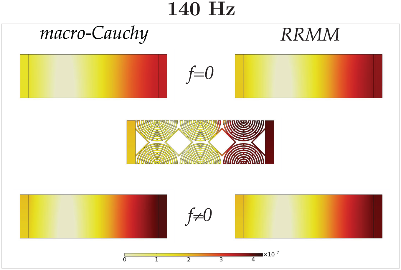
Comparison of the displacement field of the metamaterial specimen Δ with the macro-Cauchy and the RRMM when
Completely analogous conclusions can be drawn here for the interface forces as those presented for a frequency of 80 Hz. This means that both the RRMM and the macro-Cauchy interface forces get “closer” to the microstructured traction’s average as soon as triggering interface forces. At the current frequency of 140 Hz (see Figure 14), 12 the two solutions are equally good after the introduction of suitable interface forces since the dispersion is still small in this low frequency.
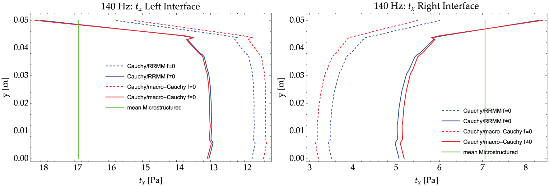
Tractions on the Cauchy side of the Cauchy plate/metamaterial interfaces (left and right) for the RRMM and for the macro-Cauchy when
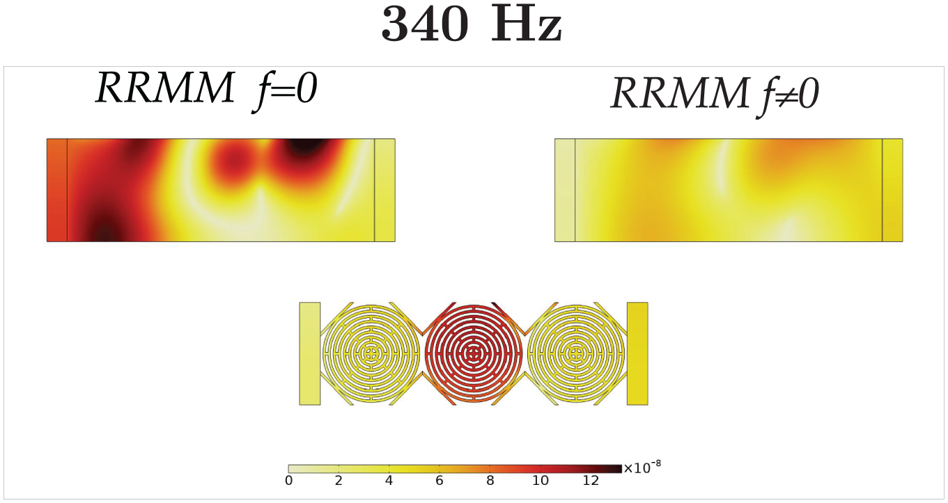
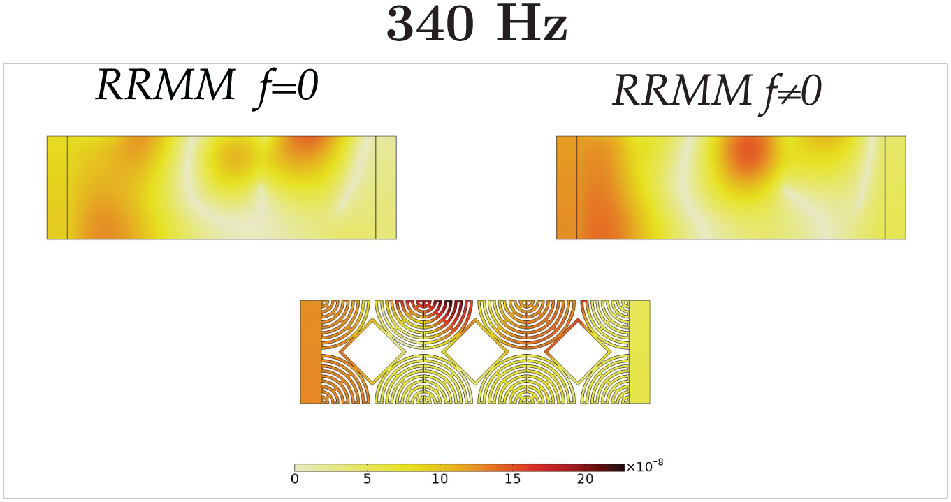
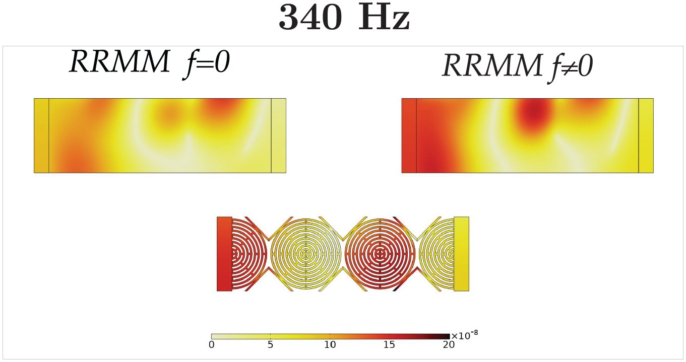
6.1.3. Frequency: 340 Hz
At this frequency and also for values slightly lower or higher in the interval of 200–400 Hz, the four cuts have massive differences. This is because the wavelength gets smaller (around one to two times the size of the specimen), interacts with the microstructure, and these boundary effects are now governing the whole response of the
Figures 15–18 show that in this frequency interval, the wavelength is comparable to the size of the specimen; therefore, more complex expressions of
Comparison of the displacement field of the metamaterial specimen A with the RRMM when
Comparison of the displacement field of the metamaterial specimen B with the RRMM when
Comparison of the displacement field of the metamaterial specimen Γ with the RRMM when
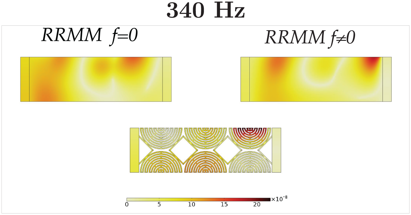
Comparison of the displacement field of the metamaterial specimen Δ with the RRMM when
Particular attention should be paid to cases where one wants to use homogenized models specifically for frequencies with corresponding wavelengths comparable to or smaller than the specimen’s size, when these frequencies are not “close enough” to a band-gap region in order for the metamaterial’s attenuation mechanisms to start being activated.
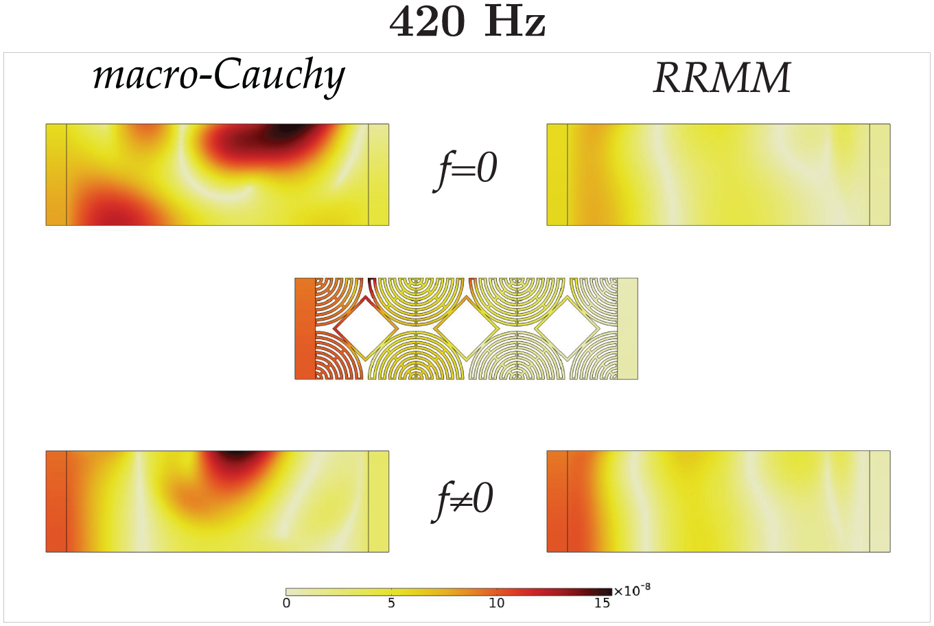
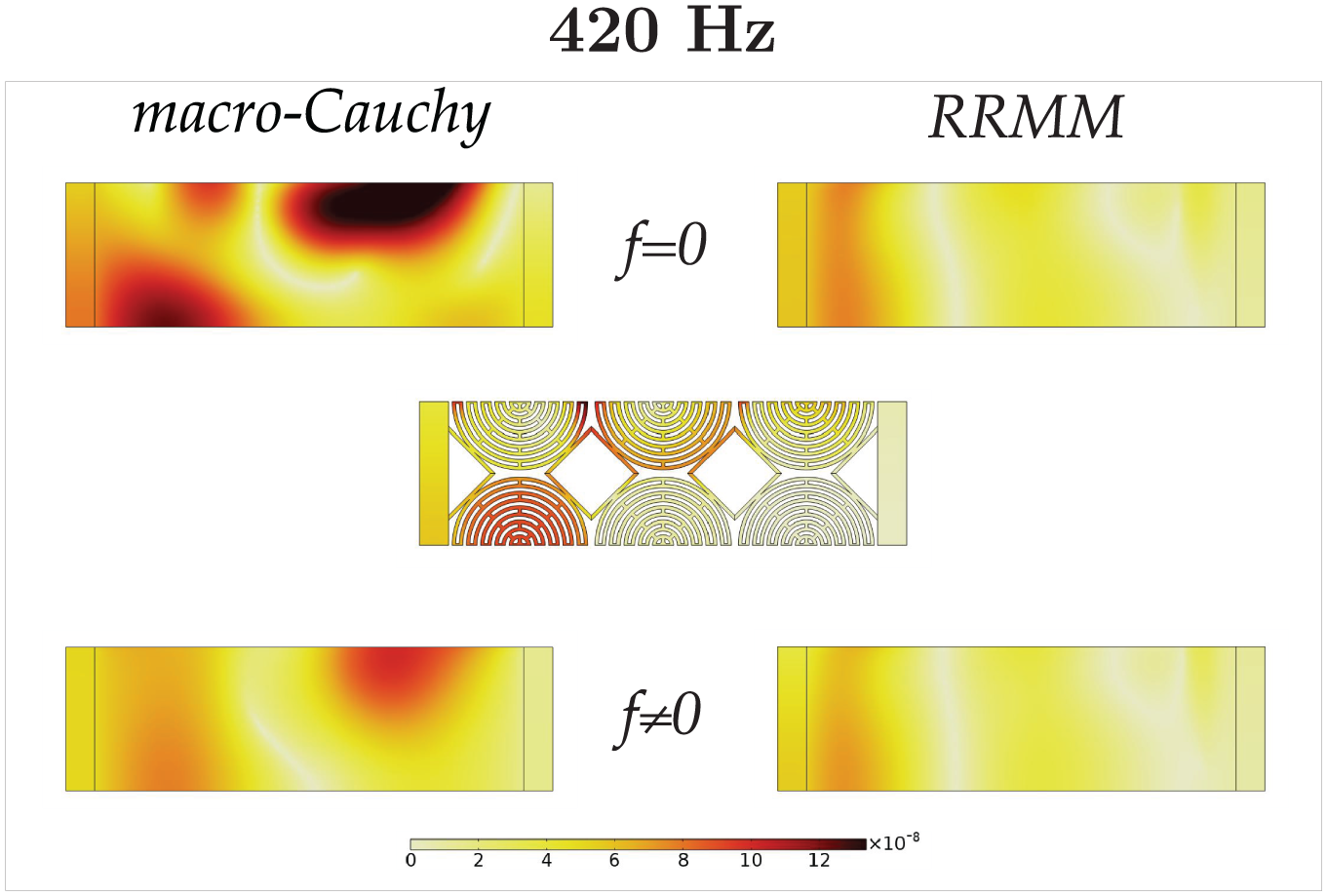
6.1.4. Frequency: 420 Hz
We continue analyzing the homogenized Cauchy and RRM simulations and the corresponding comparison to the microstructured ones for the frequency of 420 Hz. Here, the wavelength is smaller than the one at 340 Hz (see Table 2) which would indicate more pronounced boundary effects, but because we are now close to a band-gap region, the attenuation mechanisms of the metamaterial are being activated, causing some destructive interference of the waves instead of more pronounced boundary effects. Hence, expression (19) is again sufficient to capture the overall response (see Figures 19–22). Moreover, the dispersion curves start showing a strong dispersive behavior (see Figure 6). This implies that, while the RRMM gives good results when introducing the suitable interface forces, the long-wavelength limit Cauchy model is not able anymore to recover the correct behavior even when interface forces are triggered. The long-wavelength limit Cauchy model gives rise to unphysical responses which are due to the fact that dispersion cannot be described in the framework of Cauchy linear-elasticity.
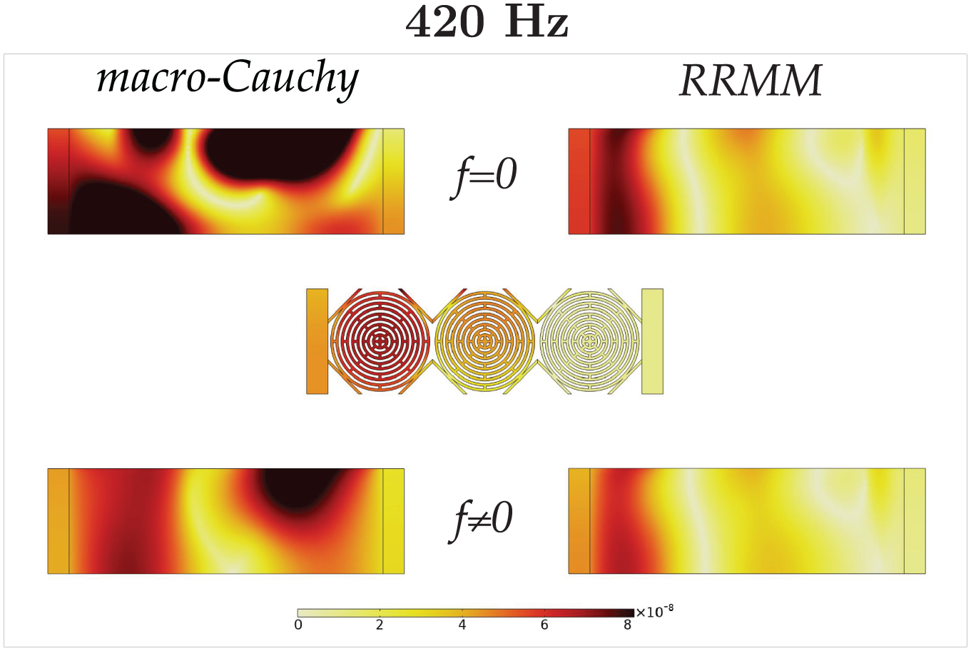
Comparison of the displacement field of the metamaterial specimen A with the macro-Cauchy and the RRMM when
Comparison of the displacement field of the metamaterial specimen B with the macro-Cauchy and the RRMM when
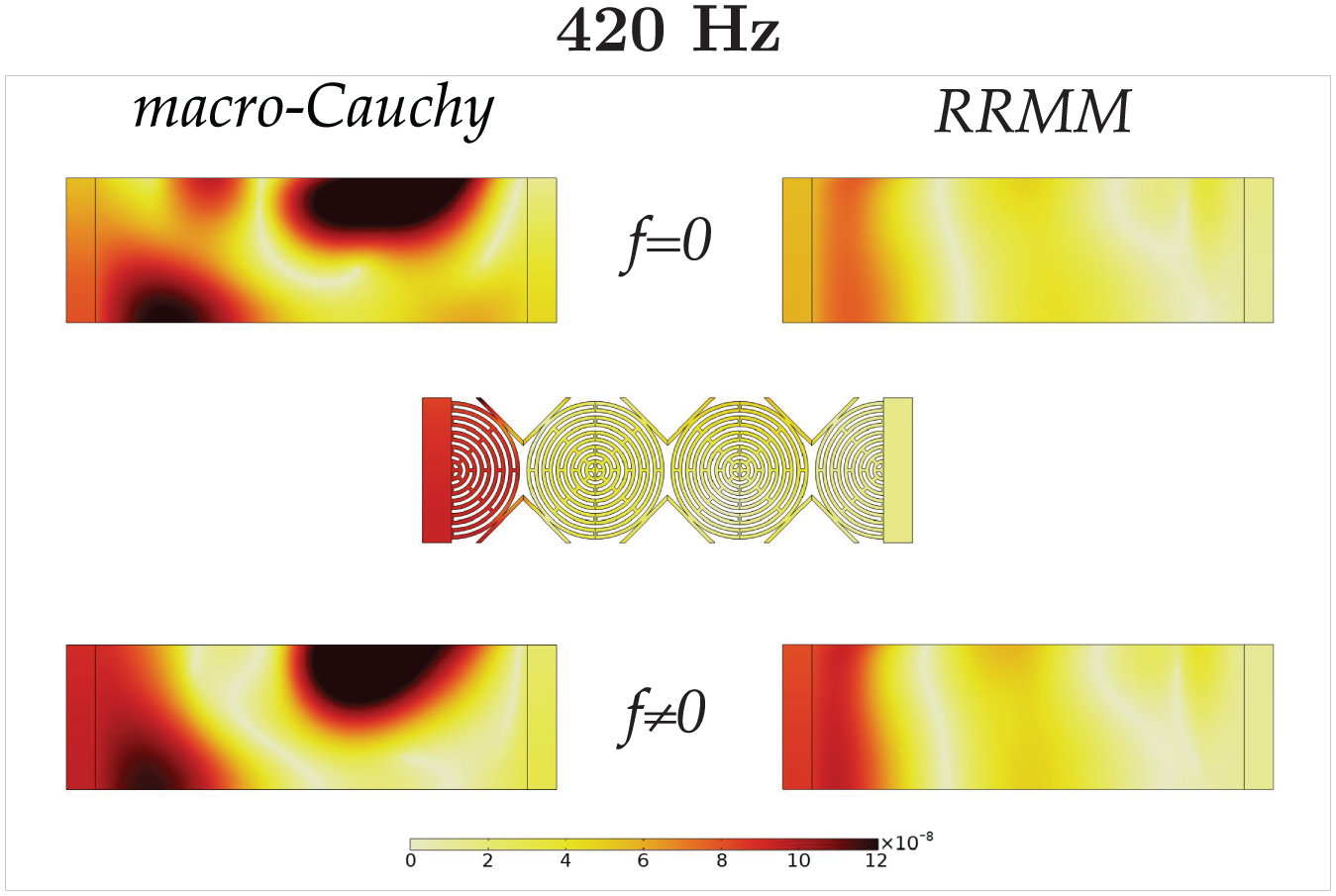
Comparison of the displacement field of the metamaterial specimen Γ with the macro-Cauchy and the RRMM when
Comparison of the displacement field of the metamaterial specimen Δ with the macro-Cauchy and the RRMM when
Here, we can observe that the initial (without interface forces correction) tractions for the Cauchy model are not only quantitatively less close to the mean microstructured traction than the RRM one, but we can also start seeing a qualitative deviation of the macro-Cauchy initial traction (see Figure 23). This is because a correct description of the bulk response becomes more and more important at higher frequencies where dispersion becomes higher. Moreover, we can see that while the corrected RRM and macro-Cauchy tractions with interface forces are comparable on the left interface, the RRM one is by far better on the right interface. We thus see how the RRM response starts having better performances as soon as frequency increases. We note that according to Table 2, the wavelength is already smaller than twice the size of the structure and therefore comparable to the size of the unit cell. The overall response starts deviating from a plane-wave-like propagation and the so-called separation of scales does not hold in this case (
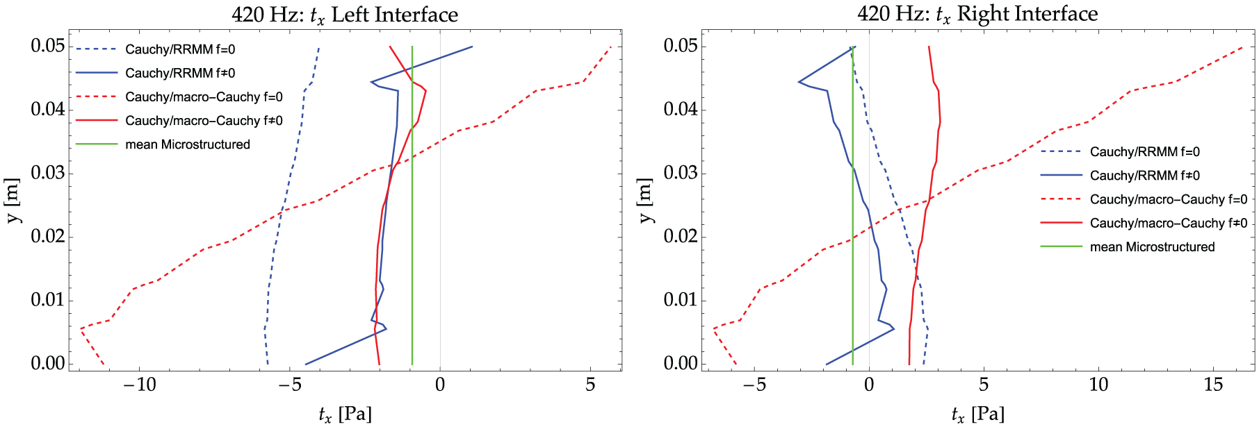
Tractions on the Cauchy side of the Cauchy plate/metamaterial interfaces (left and right) for the RRMM and for the macro-Cauchy when
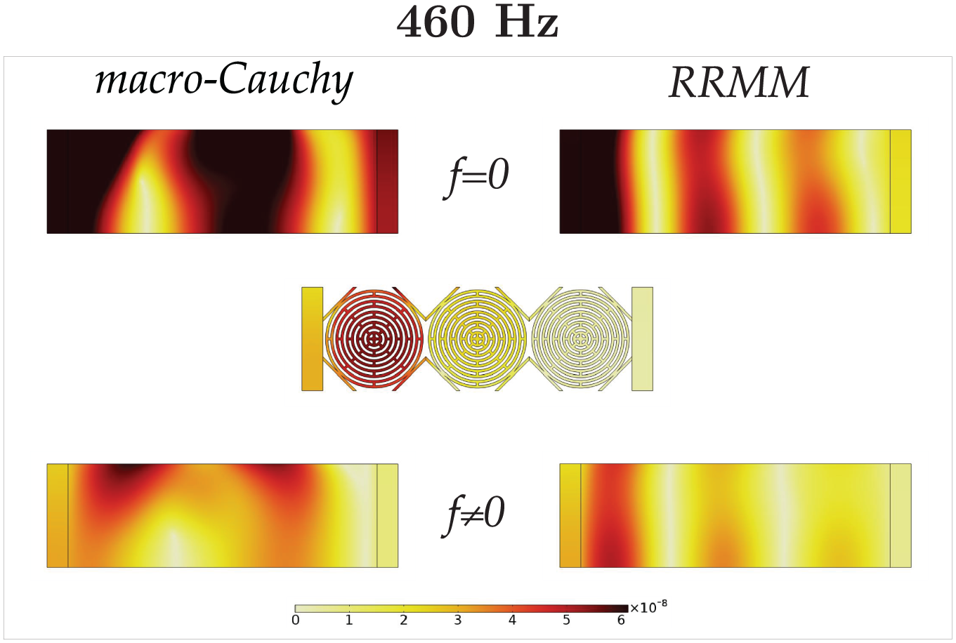
6.1.5. Frequency: 460 Hz
We continue analyzing the homogenized Cauchy and RRM simulations and the corresponding comparison to the microstructured ones for the frequency of 460 Hz. This frequency shows strong dispersive behavior (see the seventh point in Figure 6) and is directly below the band gap.
For the frequency of 460 Hz, considerations analogous to the frequency of 420 Hz hold.
At the present frequency, it becomes more evident how the RRMM outperforms with respect to the macro-Cauchy as soon as suitable interface forces are introduced (see Figures 24–28). All the considerations done for the frequency of 420 Hz also apply here. The wavelength at the present frequency is closer to the size of the unit cell than the previous case. The separation of scales is not holding here, but the RRMM still gives good solutions.
Comparison of the displacement field of the metamaterial specimen A with the macro-Cauchy and the RRMM when
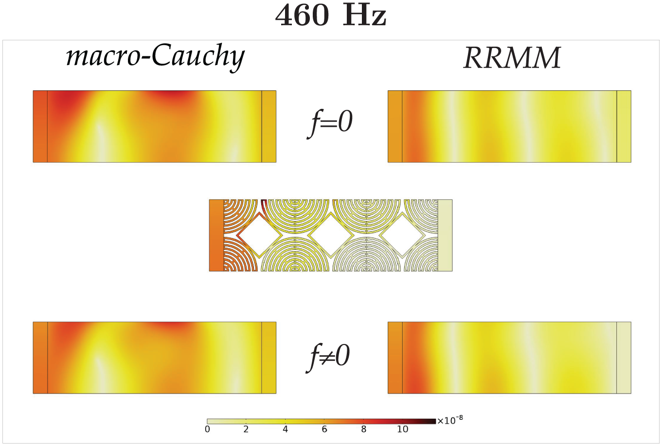
Comparison of the displacement field of the metamaterial specimen B with the macro-Cauchy and the RRMM when
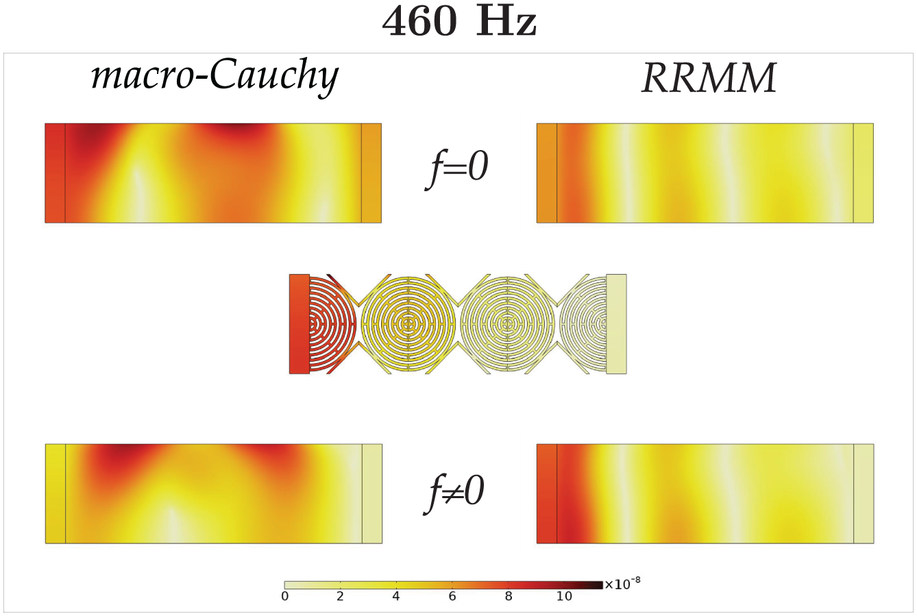
Comparison of the displacement field of the metamaterial specimen Γ with the macro-Cauchy and the RRMM when
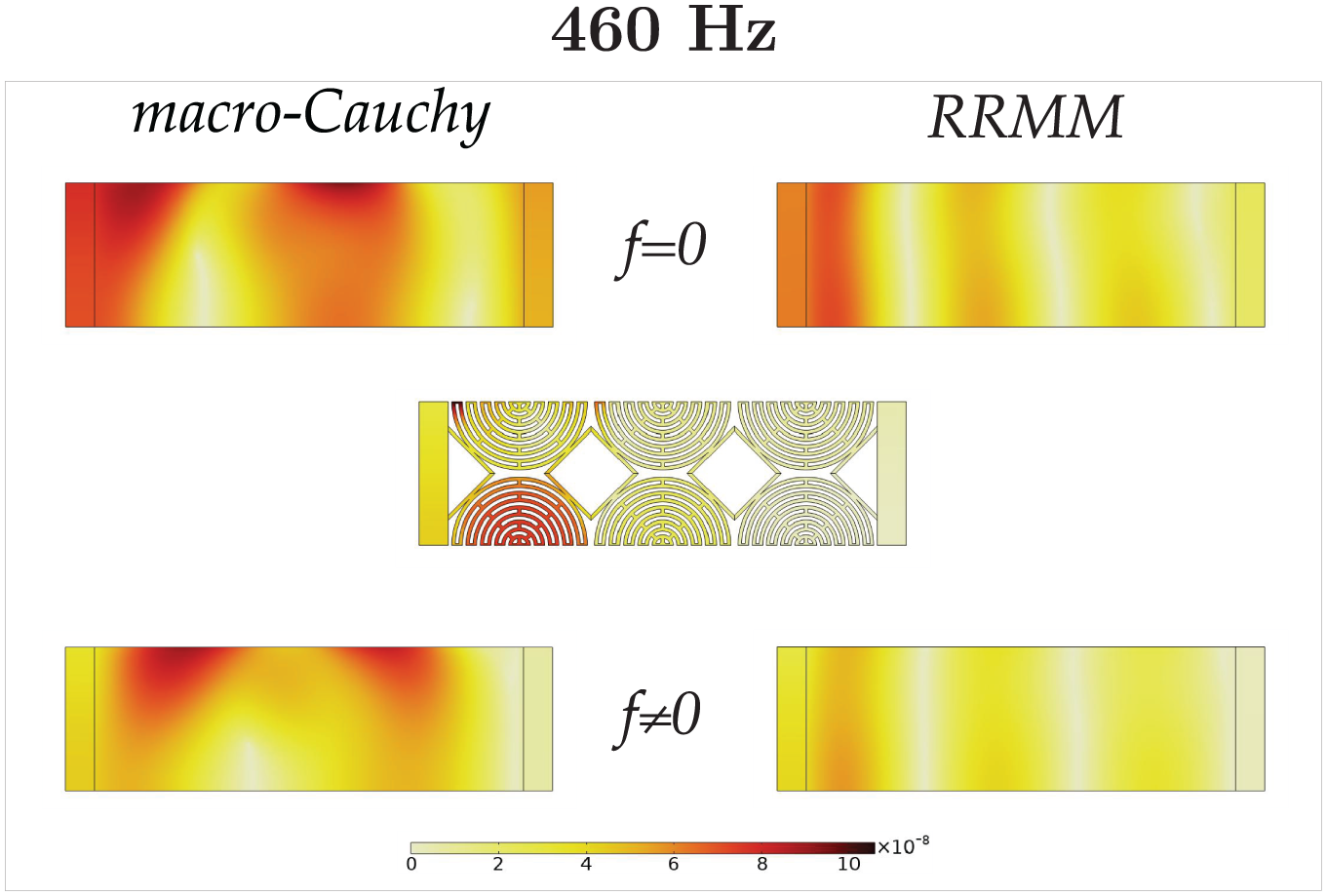
Comparison of the displacement field of the metamaterial specimen Δ with the macro-Cauchy and the RRMM when
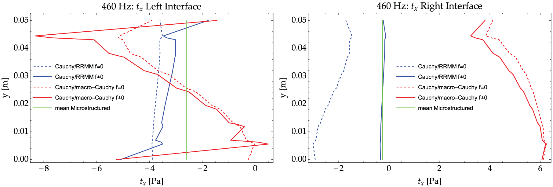
Tractions on the Cauchy side of the Cauchy plate/metamaterial interfaces (left and right) for the RRMM and for the macro-Cauchy when
6.1.6. Frequency: 700 Hz
We continue analyzing the homogenized Cauchy and RRM simulations and the corresponding comparison to the microstructured ones for the frequency of 700 Hz. This frequency is in the lower part of the band gap (see the eighth point in Figure 6).
The frequency of 700 Hz is located in the band-gap region of the considered metamaterial. Boundary effects are limited to the interface close to the surface where the external load is applied (left interface). Since wave propagation is not allowed through the metamaterial’s bulk, the deformation is concentrated at the first unit cell. Depending on the unit-cell’s “cut,” the solution is quite different and macroscopic bending of the left Cauchy plate can occur as a consequence of a heterogeneous microdeformation field of the unit cells belonging to the first cell’s layer close to the left interface (see Figures 29–33).
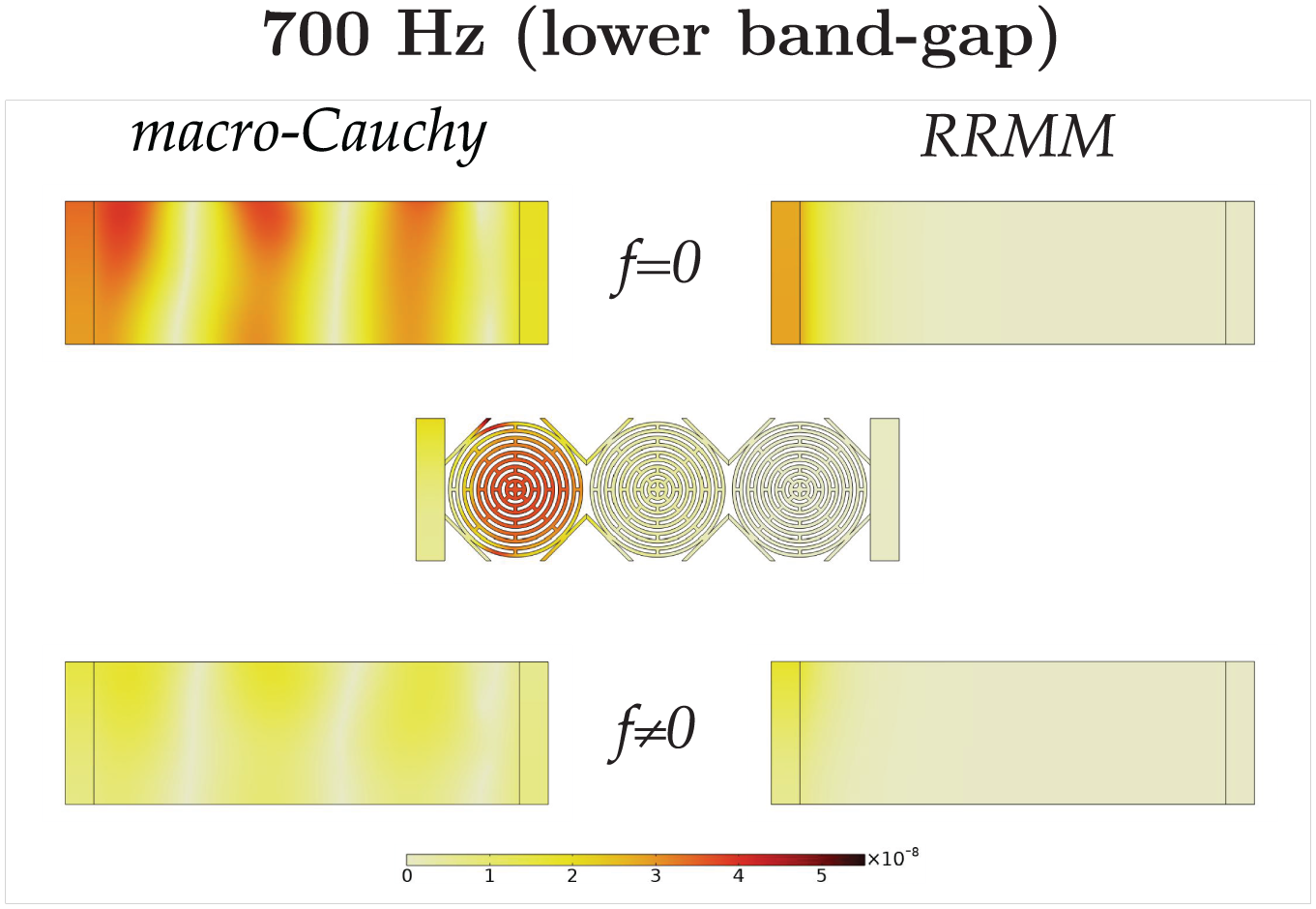
Comparison of the displacement field of the metamaterial specimen A with the macro-Cauchy and the RRMM when
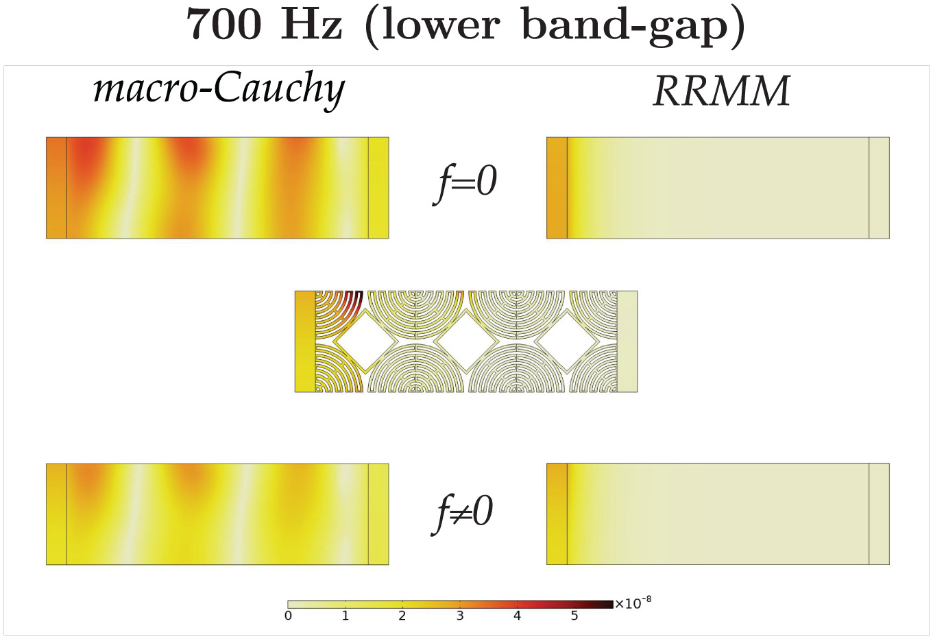
Comparison of the displacement field of the metamaterial specimen B with the macro-Cauchy and the RRMM when
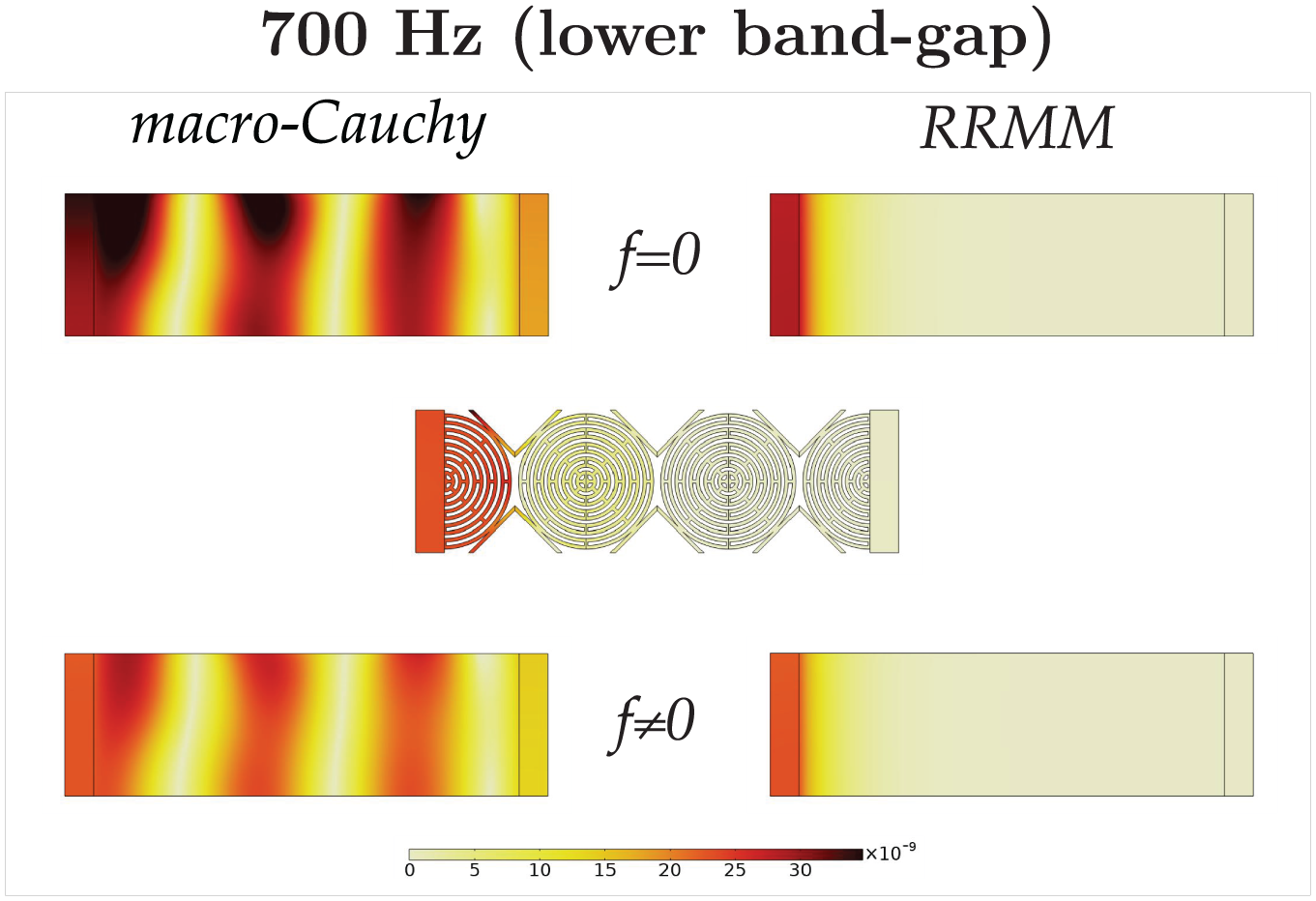
Comparison of the displacement field of the metamaterial specimen Γ with the macro-Cauchy and the RRMM when

Comparison of the displacement field of the metamaterial specimen Δ with the macro-Cauchy and the RRMM when
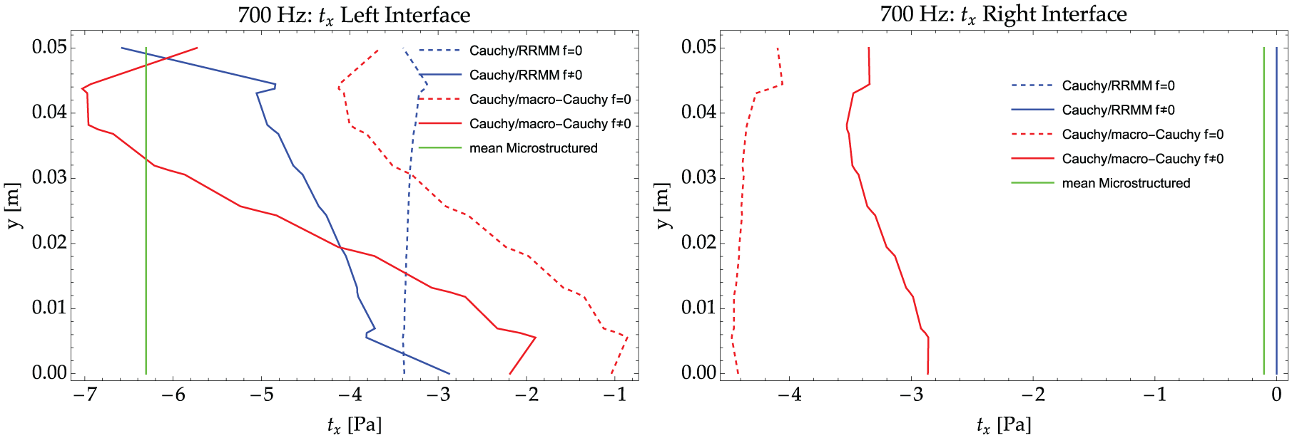
Tractions on the Cauchy side of the Cauchy plate/metamaterial interfaces (left and right) for the RRMM and for the macro-Cauchy when
The RRMM can correctly describe the band-gap behavior of the considered specimen for all four “cuts,” as soon as suitable interface forces are introduced. On the contrary, the long-wavelength limit Cauchy model fails to recover the correct solution also when triggering interface forces. This is due to the fact that Cauchy models are not able to describe band-gap behaviors.
6.1.7. Frequency: 1500 Hz
We continue analyzing the homogenized Cauchy and RRM simulations and the corresponding comparison to the microstructured ones for the frequency of 1500 Hz. This frequency is in the upper limit of the band gap (see the tenth point in Figure 6). Considerations similar to the frequency of 700 and 1100 Hz hold here both for the displacement and for the traction (see Figures 34–38).
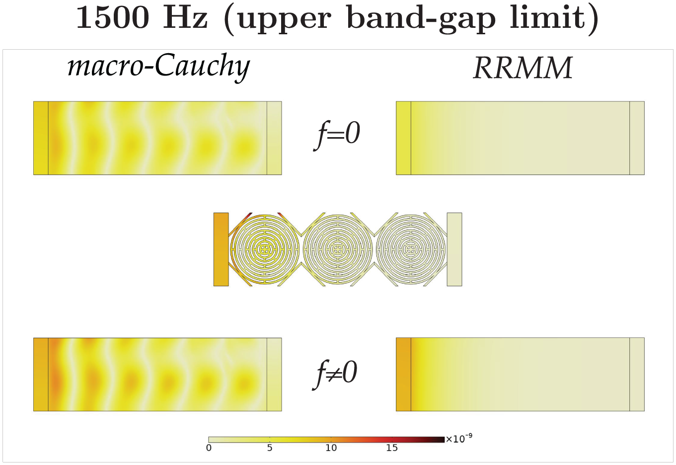
Comparison of the displacement field of the metamaterial specimen A with the macro-Cauchy and the RRMM when
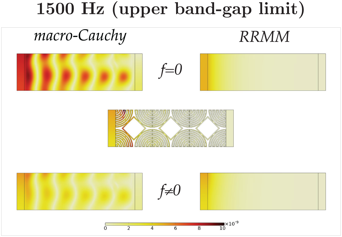
Comparison of the displacement field of the metamaterial specimen B with the macro-Cauchy and the RRMM when
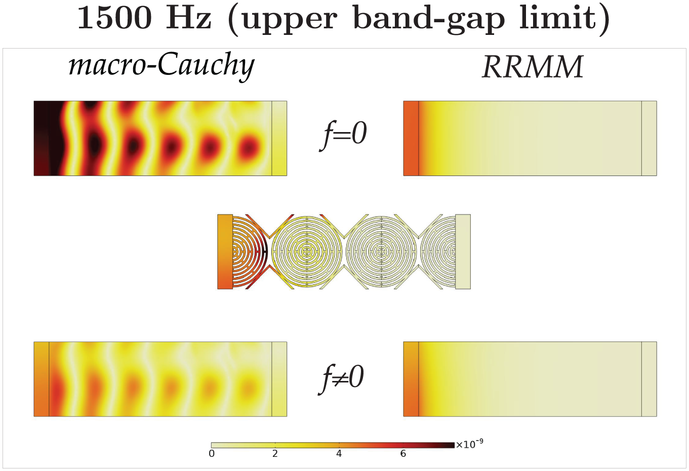
Comparison of the displacement field of the metamaterial specimen Γ with the macro-Cauchy and the RRMM when
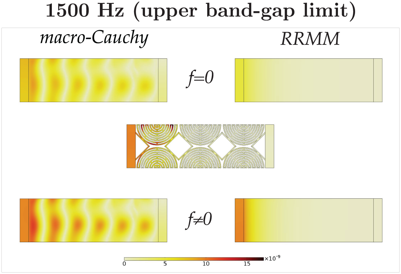
Comparison of the displacement field of the metamaterial specimen Δ with the macro-Cauchy and the RRMM when
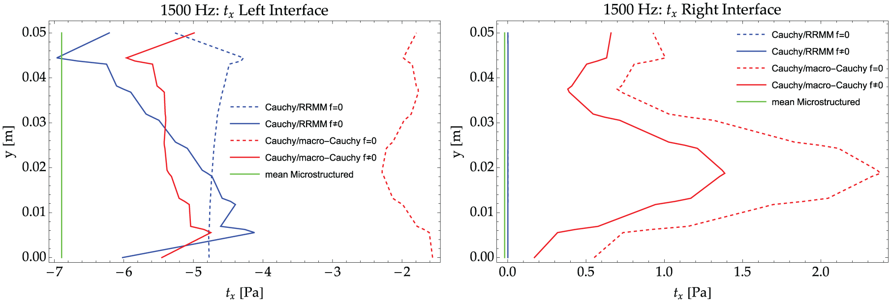
Tractions on the Cauchy side of the Cauchy plate/metamaterial interfaces (left and right) for the RRMM and for the macro-Cauchy when
7. “Cut”-dependent effectiveness of the metamaterial
In this section, we will discuss the implications of choosing a different unit-cell “cut” on the microstructured metamaterial’s behavior with focus on transmissibility. In most cases, the frequency region of interest on a transmissibility plot is the band-gap region, where we witness very low values of wave transmission, and therefore, this region can be used for vibration isolation. In the following, we also show that the possibility of constructing the finite-size metamaterial from different unit-cell “cuts” could potentially reveal new frequency regions of interest.
7.1. Transmissibility
We will now discuss the transmissibility of the four finite-size specimens. Transmissibility is defined as the ratio of output to input acceleration (or equivalently displacement, velocity or force) for a given vibration test. In our case, we choose the absolute value of the acceleration at each point on the right Cauchy plate as the measure of output, and similarly, the input is the absolute value of the acceleration at each point on the left Cauchy plate where the excitation force is applied. To have a single value of transmissibility for each frequency (instead of a point-wise comparison), we take their averages on each plate and call Transmissibility the ratio

where
The transmissibility plot of all the four microstructured metamaterials, for the pressure test presented in section 4 can be seen in Figure 39 where we can observe vast differences in the transmissibility values in the band-gap region between the four specimens. This emphasizes again that even if the four “cuts” produce the same infinitely big metamaterial, given the finite size of real applications, the choice of unit-cell “cut” becomes of paramount importance.
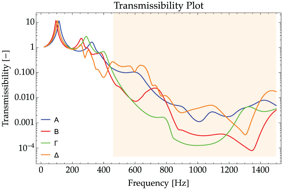
Transmissibility plot for the four microstructured specimens. The y-axis is presented in a logarithmic scale and the band-gap range is indicated with light orange color.
By choosing the four different “cuts” for constructing our finite-size specimen, we end up with four different metamaterial’s specimens of finite size. One could believe that the only common thing between the four periodic structures is the fact that they correspond to the same dispersion curves (in an infinitely big domain), and thus, they should have the same “vibrational characteristics.” However, due to the finite size of these structures, we end up with a different geometry on the boundaries of each specimen, which gives us vastly different boundary effects. Furthermore, different structures even of the same size can possess different eigenfrequencies of vibration, leading to different results for identical frequencies. All these factors lead to the difference in the transmissibility of the four specimens in Figure 39.
7.2. Reduced transmissibility in a non-band-gap frequency range
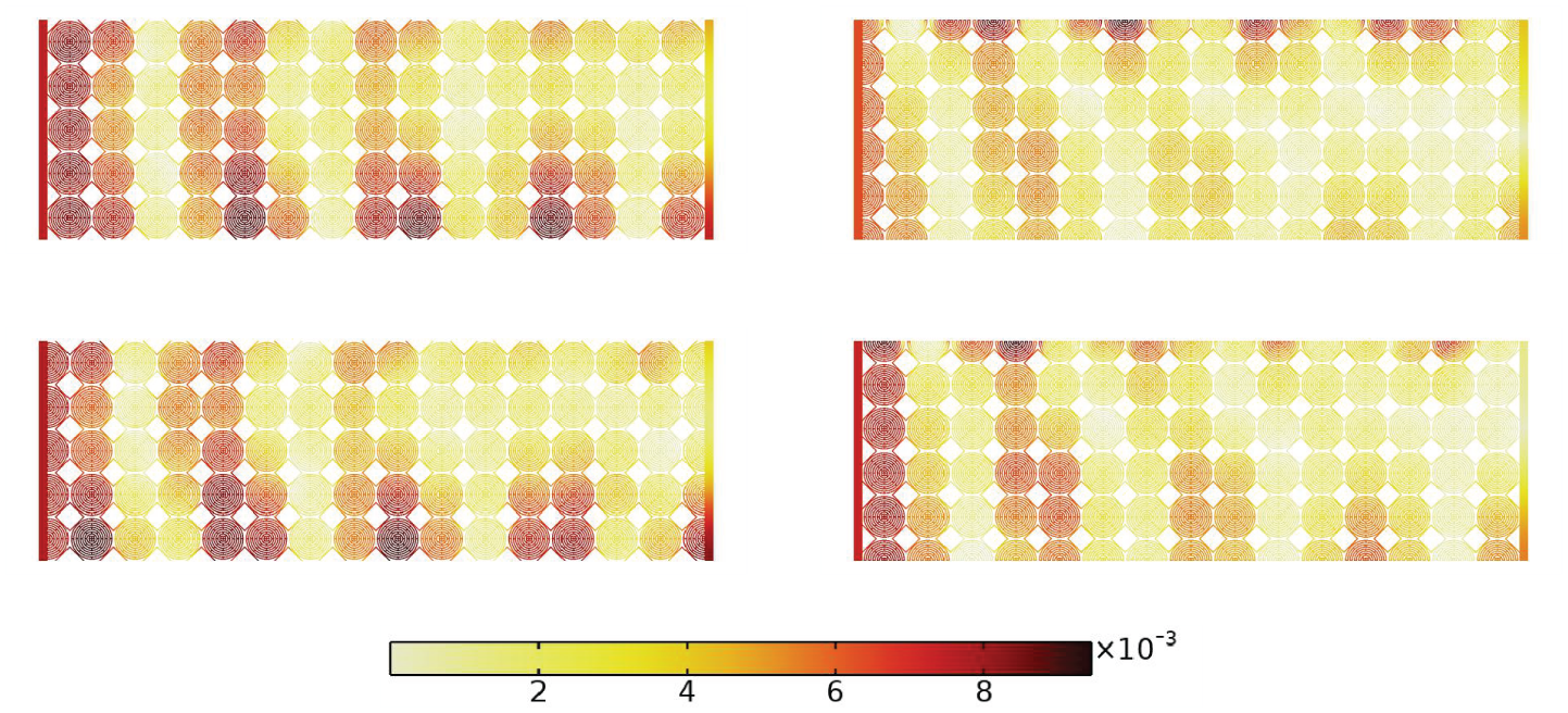
The transmissibility plot (Figure 39) reveals a small region (340-425 Hz), for which only cut Δ has a reduced transmissibility, and this region does not fall in the frequency region of the band gap. Specifically, the transmissibility values for cut Δ in this region are around 10%. These transmissibility values are not comparable to the band gap, but still the attenuation is big enough to be used for potential shielding applications. A zoom in the transmissibility plot in Figure 40 shows better the discussed absorption property, and the displacement field for an indicative frequency of 350 Hz in this region can be seen in Figure 41.
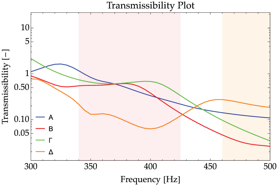
Zoom in the transmissibility plot: the frequency region of interest is indicated with light red color.
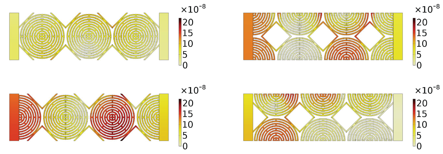
Displacement field at 350 Hz for the four specimens. Specimen A (top left), B (top right), Γ (bottom left), and Δ (bottom right).
7.3. Independent tests using bigger specimens: limits of Bloch-Floquet analysis
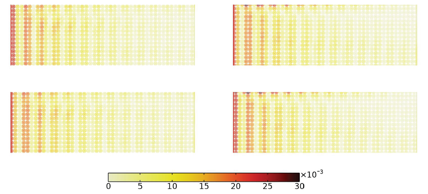
Since the analyzed 3×2 specimens have vastly different displacement field solutions, we will now also increase the size of the structures in steps, to understand how much it needs to be increased in order for the four specimens to have a similar displacement field, i.e., what is the size of the specimens to consider boundary effects (and thus, the need for interface forces in the RRM setting) as negligible. We proceed with this task but we change the excitation to a displacement instead of a force so that we are able to compare the convergence of the four different cases towards one big metamaterial sample. We present here the results for specimens of size 3×2, 9×6, 15×10, 30×20, and 45×30 for the frequency of 200 Hz and all the four “cuts.”
7.3.1. 3×2 cells, Lspecimen = 15 cm, wavelength λ = 35 cm
For samples consisting of 6 unit cells overall, vast differences are apparent in the response of the metamaterials. This is due to the very small size of the samples which makes boundary effects predominant in the response (see Figure 42).
Displacement field for the four original 3×2 specimens at the frequency of 200 Hz. Specimen made out of cut A (top left), cut B (top right), cut Γ (bottom left), and cut Δ (bottom right).
7.3.2. 15×10 cells, Lspecimen = 75 cm, wavelength λ = 35 cm
Even with a sample consisting of 150 unit cells overall, boundary effects still produce significant differences between the different “cuts” that are prominent also in the bulk of the material (see Figure 43). This means that the specimen with an overall length of 75 cm is still too small compared to the wavelength 35 cm.
Displacement field for the four 15×10 specimens at the frequency of 200 Hz. Specimen made out of cut A (top left), cut B (top right), cut Γ (bottom left), and cut Δ (bottom right).
7.3.3. 45×30 cells, Lspecimen = 225 cm, wavelength λ = 35 cm
For our biggest samples consisting of 1350 unit cells, all four solutions converge regarding bulk response. However, some boundary effects are still visible (see Figure 44).
Displacement field for the four 45×30 specimens at the frequency of 200 Hz. Specimen made out of cut A (top left), cut B (top right), cut Γ (bottom left), and cut Δ (bottom right).
7.3.4. Summary
The main assumption of Bloch–Floquet analysis is that the material is extended to infinity by periodic boundaries, i.e., the actual size of the specimen is infinitely big, and thus, the metamaterial has no boundaries. However, the dispersion curves coming from Bloch–Floquet analysis are inevitably used as a design tool in finite-size metamaterial applications, often disregarding boundary effects that we showed can become predominant as soon as reducing the specimen’s size to finite-sized problems. Thus, the question arises, what is the minimum size of a finite-sized metamaterial so that we are allowed to neglect boundary effects?
Usually, the answer given is that a very big number of unit cells must be used to approximate well a metamaterial extended to infinity often unfeasible for finite-sized applications. By using more unit cells, the length of the boundary of the metamaterial scales linearly while the area of the bulk scales quadratically, and thus, the ratio of boundary to bulk tends to zero.
Another more interesting answer coming from the results in this section is the following: Boundary effects can be neglected if the size of the specimen is “big enough,” i.e., bigger than a certain threshold, so that finite-sized specimens constructed from different cell’s cuts show no qualitative difference in their behavior. This implies that, the RRM modeling of specimens that are bigger of this threshold would not need any more non-vanishing interface forces to provide the correct solution. From the above results, we can see that even for a 45×30 specimen, there are still some different boundary behaviors for the different cuts. Therefore, we have not yet found the appropriate size for which boundary effects can be fully neglected. At this size, our enriched continuum would not need surface forces to reproduce the different response associated to the four different cell’s cuts. On the contrary, it can be noticed that the “bulk” response already becomes very similar in the four specimen’s types as soon as the number of unit cells is increased.
8. Conclusion
In this paper, we have demonstrated that introducing the concept of interface forces is essential for modeling the response of finite-size metamaterials within a homogenized framework. By leveraging the RRMM which has proved excellent performance in describing the bulk behavior of metamaterials, we enhanced the model by incorporating the concept of interface forces that must be considered at the interfaces of all metamaterials.
We elucidated the significance of this new concept through an in-depth analysis of a benchmark compression/extension test as well as a shear test. We showed that for the considered benchmark case, the interface forces should exhibit the form:

where
Our findings explicitly indicate that boundary effects and, consequently, interface forces can significantly impact finite-sized specimens. This paper conclusively establishes that homogenization schemes that do not account for the interface forces arising at the “homogenized” interfaces may result in substantial errors when these models are applied to model real structures which are inherently finite in size.
Footnotes
Appendix 1
Appendix 2
Funding
Angela Madeo, Jendrik Voss, and Plastiras Demetriou acknowledge support from the European Commission through the funding of the ERC Consolidator Grant META-LEGO, no. 101001759.
Conflict of interest
The authors declare that they have no conflict of interest to this work.