
Abstract
The analytical solution of an elliptic dielectric cavity in an infinite dielectric plate is taken as basis to investigate a Griffith crack problem which is obtained by letting the semi-minor axis tend towards zero. In the course of this, an erroneous conformal mapping, commonly employed in literature and correctly reproducing the electric field only in a part of the physical space, is rectified. Interpreting the elliptic interface as faces of a mechanically opened crack which is exposed to an oblique remote electric field, surface charges and electrostatic tractions are calculated. In contrast to the established capacitor analogy model, approximately yielding electric charge densities and Coulombic tractions from displacements and electric potentials in the undeformed crack configuration, the work at hand provides exact solutions accounting for different implications of the crack curvature and for the inclination of the electric field. Crack weight functions are finally used to calculate stress and electric displacement intensity factors. As turns out, the surface charges of the capacitor analogy represent an excellent substitute for the exact electric boundary conditions within a relevant range of parameters, whereas inaccurate Coulombic tractions in the vicinity of crack tips may lead to a significantly overestimated mode I stress intensity factor.
1. Introduction
In fracture mechanics of dielectrics and piezoelectrics, electromechanical boundary value problems of cracked bodies under mixed loading conditions are considered in general. Within infinitesimal strain theory, being appropriate in the case of brittle material, current and initial configurations are not distinguished, allowing for a problem formulation with respect to the latter. Several established methods for the analytical and numerical solution of these problems are commonly pursued in literature, where the electromechanical coupling and material anisotropy represent aggravating circumstances. On the one hand, analytically, integral transformations [1–3] or Green’s functions [4–6] are oftentimes exploited. In the case of two-dimensional problems, complex analysis provides a rich framework from which the powerful Stroh formalism [7–9] and extended Lekhnitskii theory [10, 11] emanate. Moreover, by conformally mapping complicated to simple geometries, solutions may be elegantly adjusted to values prescribed on arbitrary boundaries [10, 12, 13]. On the other hand, the finite element method [14–18] and the boundary element method [6, 19–22] are predominant in the field of numerical studies, where the latter is based on Green’s functions in infinite domains and, upon dispensing with volume discretization, for crack problems oftentimes turns out superior to the former in terms of computational efficiency.
When dealing with sharp cracks in linear elastic fracture mechanics disregarding cohesive zones as well as internal pressure, the crack faces represent Neumann boundaries, where zero tractions are prescribed. The boundary conditions on the crack faces in a dielectric medium, however, are less unambiguous since upon loading, a crack medium which is either conductive or of permittivity
In order to properly account for this condition in the electrostatic boundary value problem, both solid body and crack medium have to be subjected to Maxwell’s equations as well as appropriate interface conditions on the crack faces. Circumventing this effort, researchers have deduced two special cases of boundary conditions from the general two-domain problem [23]. The impermeable crack model, initially introduced in Deeg [24] and Pak [25], employs
In an attempt to capture the circumstances of a crack medium with finite permittivity
Extending the capacitor analogy and building on the work of Kemmer and Balke [39], Landis and McMeeking [40] introduced Coulombic tractions acting on the crack faces. These tractions are obtained from the electric field and electric displacement inside the crack and represent a simplification of electric surface tractions due to Maxwell stress. The latter has been controversially discussed by renowned physicists in the past [41, 42] and, besides tractions, gives rise to body forces and couples induced by electric and magnetic fields [43]. Unfortunately, several formulations of the Maxwell stress tensor are known nowadays, however, none could be validated without contradiction to date. In dielectric and piezoelectric crack models, tractions emanating from a simplification of the approach according to Minkowski prevail. The closing effect of the Coulombic tractions on various crack configurations has been extensively investigated by several researchers [20, 21, 44–49], who generally recorded a partially considerable reduction of the mode I stress intensity factor (SIF). Altogether, the capacitor analogy, sometimes complemented by the Coulombic tractions, is commonly applied in corresponding literature of both analytical and numerical nature [16,18,44–53].
Notwithstanding, this model exhibits some fundamental deficiencies in the context of considering finite deformation of a crack within a geometrically linear framework of solid mechanics. Consequently, the electrostatic potential used to calculate the electric field inside the crack is determined in the undeformed configuration with a closed slit crack. Furthermore, the model presupposes an electric field inside the crack which is orthogonal to the crack faces, neglecting possible tangential components at the crack tip or generally due to inclined electrical loading. Finally, when applying Coulombic tractions and surface charges on the crack faces, the unit normal of the undeformed configuration is used, disregarding curvature of the distorted crack, in particular being relevant near the crack tips. While a few works numerically investigate the errors made due to some of the above-mentioned aspects, seemingly validating at least the surface charge approximation even for inclined electric loads [54, 55], a comprehensive validation and assessment of errors based on an analytical solution of the dielectric two-domain problem is still pending. The influence of crack curvature on induced electrostatic tractions in their complete formulation and its implications on crack tip loading within a fracture mechanics framework has not yet been assessed, so the validity of the assumptions made for the Coulombic tractions remains to be evaluated in principle.
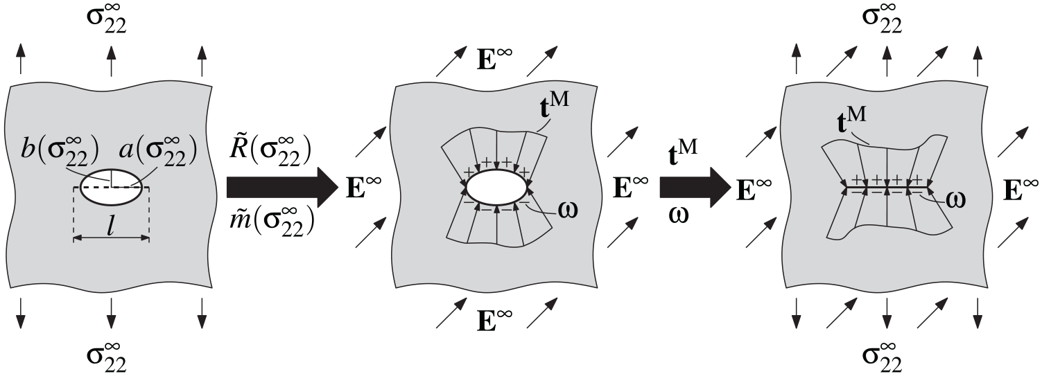
In this work, these shortcomings are covered, as the approximate surface charges and Coulombic tractions according to the capacitor analogy are checked against the corresponding true charges and tractions prevailing at a deformed crack of elliptic shape in an infinite linear-elastic isotropic dielectric plate subjected to remote electric fields and tensile stresses. Deviations of stress and dielectric intensity factors evolving from approximate surface charges and reactions, on the one hand, and true ones, on the other hand, are finally evaluated based on crack weight functions. As a result of the constitutive assumptions, electrical and mechanical boundary value problems decouple, so that the former may be solved independently of the latter. Body forces and couples due to some formulations of Maxwell stress tensors, entering the mechanical problem, are shortly outlined, however, disregarded in the calculations. The electrostatic problem has been investigated and solved by numerous authors exploiting complex analysis and conformal mapping [12,56–58]. However, some mathematical subtleties previously gone unnoticed will be pointed out in the solution procedure rigorously derived in the following. These include the proof of the existence of a holomorphic potential for the electric field on a multiply connected domain, where holomorphy alone does not suffice, as well as the complex differentiability of said potential at the slit between the ellipse’s focal points, which is usually tacitly assumed but indeed follows from the requirement of continuity. What is more, an erroneous conformal mapping commonly used in literature is rectified, having consequences for a broad range of similar mappings involved in the more general context of anisotropic elastic or piezoelectric problems, where the correct solution could hitherto only be obtained in certain subdomains of the physical plane.
2. Theoretical framework
2.1. Infinite dielectric with elliptic cavity
Let a linear isotropic dielectric body with permittivity

denote the set of all points lying inside the ellipse

In conclusion, the following boundary value problem emerges: the vector fields

in

on

are satisfied. In equation (4),


where
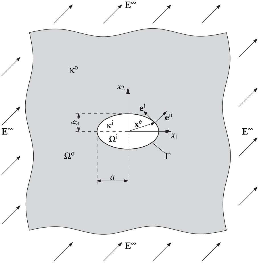
Illustration of the boundary value problem of an infinite isotropic dielectric with elliptic cavity subjected to remote electric loads.
The following solution proceeds in the style of previous studies [12,59,60], whose authors first successfully exploited complex analysis to deal with the problem at hand. Accounting for equation (2) in equation (3), while bearing in mind


for the Cartesian components of

is introduced. With equation (10) available, equations (8) and (9) disclose themselves as the Cauchy-Riemann equations for


Validity of equations (11) and (12) for arbitrary piecewise continuously differentiable closed paths in

where

Equations (8)–(14) convey the physical interpretation of its real and imaginary parts

Accounting for equation (15), it becomes clear that even

on

The problem has been simplified, so far, to identifying a scalar holomorphic potential which satisfies the corresponding conditions at the interface and infinity, equations (16) and (17), respectively. Notwithstanding, the elliptic boundary shape still complicates the solution procedure. In order to circumvent this inconvenience, consider the following conformal map
1

where

It is easily verified that in the special cases of
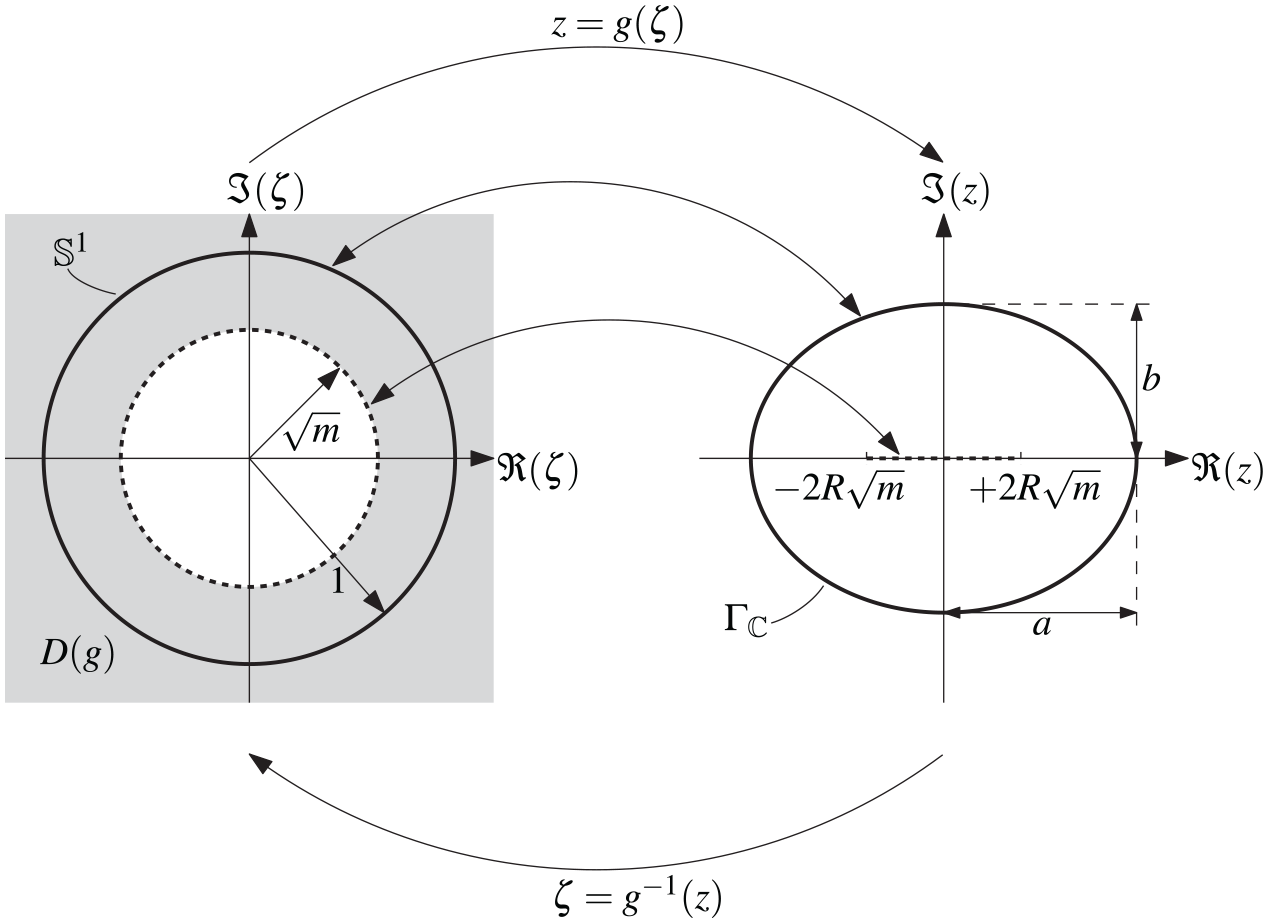
Transformation from the
The inverse function is determined by solving
Upon application of the quadratric formula, two possible solutions

As is tacitly assumed if not stated otherwise, the square root of a complex number is meant to represent the principal value with a branch cut along the negative real axis. In this case, the square root in equation (21) is discontinuous on

where the product of the two square roots is holomorphic on

where the solution
Considering the composition and the chain rule for


the problem is ultimately formulated in terms of the

on

The solution to this problem is finally obtained by expanding the functions


at

The integrals in equation (30) evaluate to


where the Cauchy integral formulae [66] have been exploited. Inserting equations (31) and (32) into equation (30), comparing coefficients and proceeding analogously with the second of equation (26) leads to the equations


Equations (34) and (36) are equivalent to

this is equivalent to the continuity of


Upon inserting equation (29), the condition

with the constants


Ultimately, in consideration of equations (13), (22), (24), and (25), the components of the electric field read
where the solution has been continuously extended on the slit
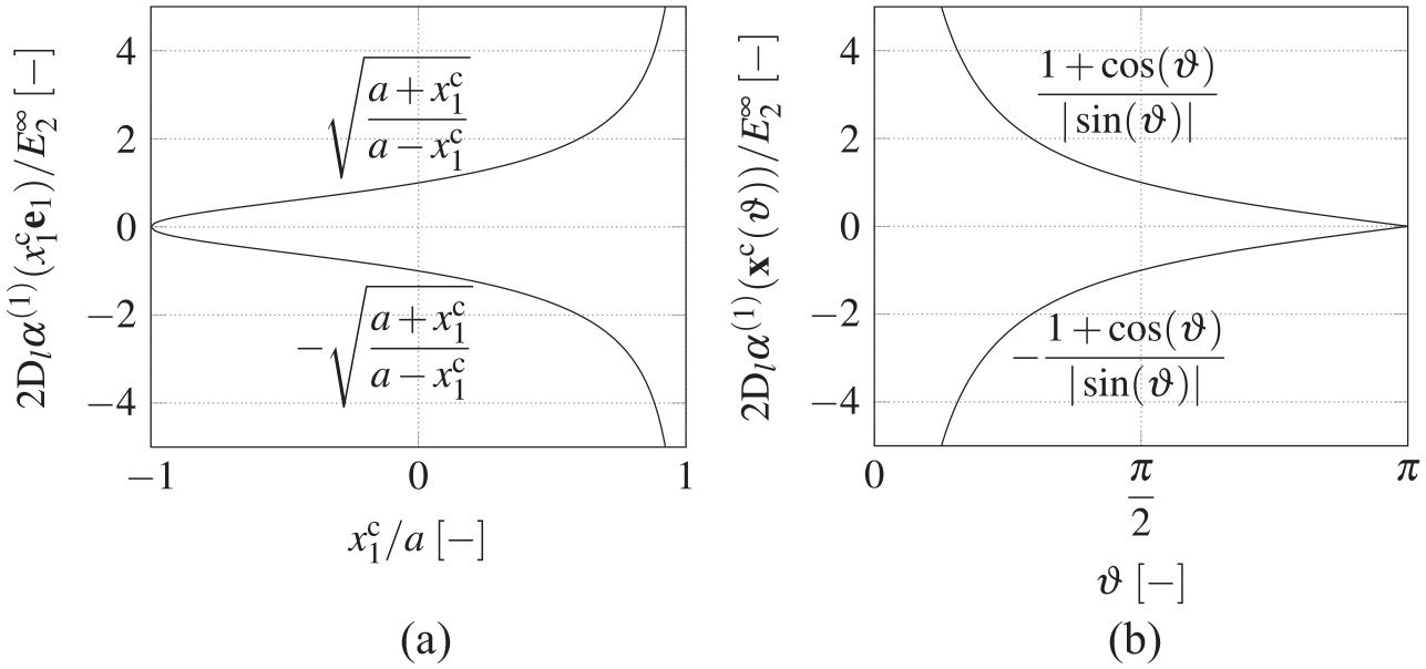
In order to reinforce the importance of accounting for the correct inverse function, Figure 3(a) shows the allocation of
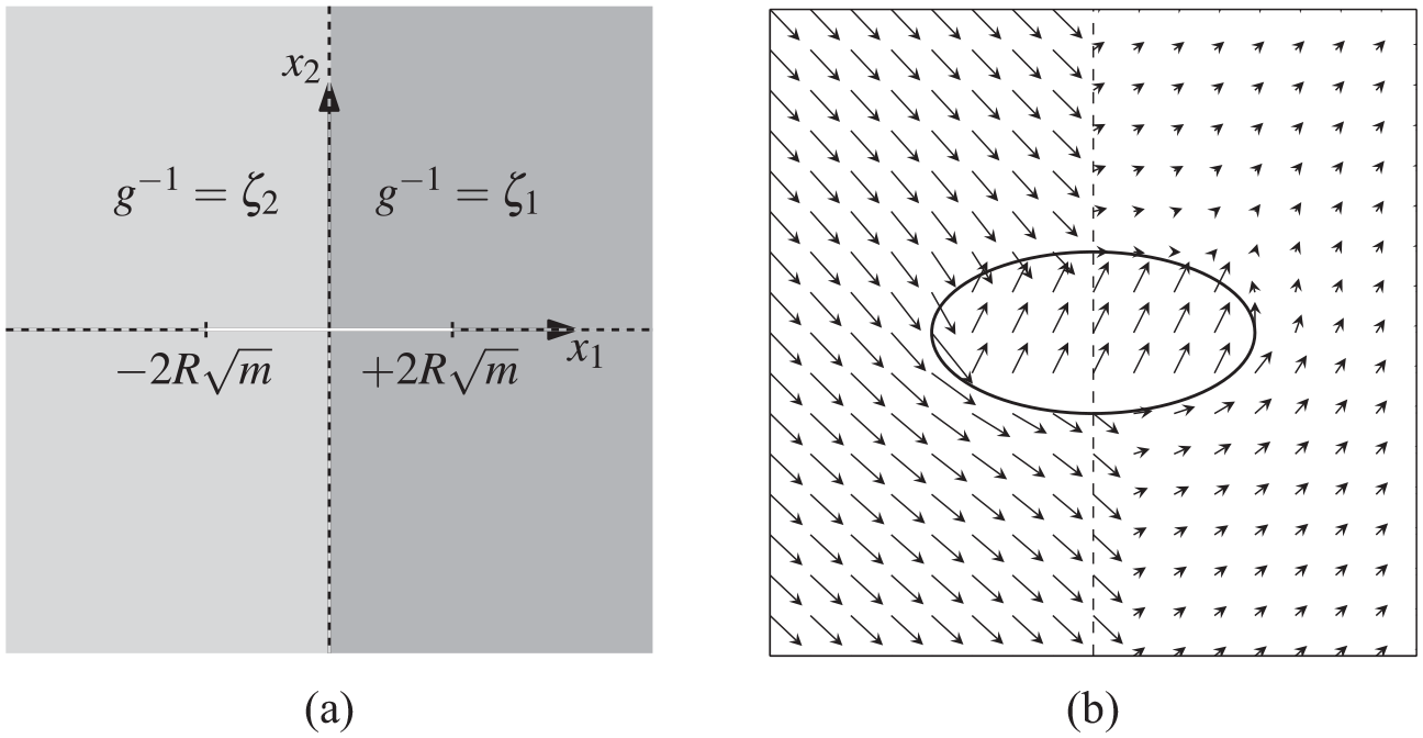
Illustration of the inverse function
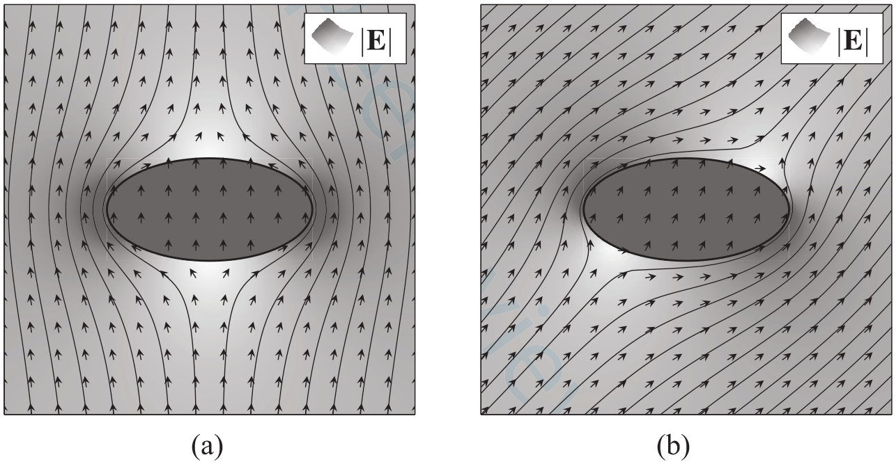
Unit vectors and magnitude of the electric field
By means of the solution equation (43), several cases relevant for the following investigations may be modeled, bearing in mind an ellipse corresponds to the geometry of a mechanically opened crack in mode I:
ellipse of finite permittivity:
impermeable ellipse:
crack of finite permittivity:
impermeable crack:
It is noteworthy that, in order to obtain the solution of an impermeable crack from equation (43),
2.2. Crack boundary conditions
Considering boundary value problems involving a crack devoid of cohesive zones from the solely mechanical viewpoint, its faces constitute Neumann boundary conditions and are usually assumed traction-free. Accounting for electrostatic facets, however, goes hand in hand with additional electric boundary conditions, which turn out less unambiguous than their mechanical counterparts. In particular, upon loading, a crack medium of permittivity
2.2.1. Capacitor analogy in the undeformed configuration
Accounting for the crack’s finite permittivity as well as opening due to loading, the semi-permeable model developed by Hao and Shen [37] considers pairwise opposite points on the crack faces as one-dimensional plate capacitors. Considering, for example, a crack of length

where

Since neither
Complementing the surface charges of equation (46) and building on the work of Kemmer and Balke [39], Landis and McMeeking [40] introduced Coulombic tractions

It follows that

Obviously, the crack’s curvature as well as
2.2.2. Capacitor analogy in the deformed configuration
Since in a non-coupled dielectric problem the solution of

Defining the electrostatic stress in analogy to equation (47), the surface charges and tractions

As shown in Appendix 15, in the case of a Griffith crack of length
2.2.3. Electrodynamic action of force
While the second of equations (51) is only strictly valid for infinite straight conducting capacitor plates enclosing a linear isotropic dielectric, it may be put into the more general context of electrodynamic action of force. This phenomenon represents an important aspect when dealing with electromechanical problems since, aside from energy, electromagnetic fields also carry momentum, which has to be accounted for in mechanical balance equations. Unfortunately, the formulations of the electromagnetic momentum density and the stress tensor in polarizable and magnetizable matter are not generally agreed upon among scientists. In fact, notable attempts to identify the correct momentum density trace back to Abraham [41] and Minkowski [42] in the early 20th century, who sparked a controversy unsolved up to date [67].
Nevertheless, there is a consensus which kind of electrodynamical coupling quantities enter the balance laws of continuum mechanics [43, 68, 69]. These will be briefly illuminated in the following, where considerations are confined to electrostatic settings with magnetic fields absent. To begin with, the local balance of linear momentum in static scenarios, neglecting gravitational body forces, valid for every point in the continuum body reads

where

with

In equation (54),


Equations (55)–(57), which may be derived from the resultant electrostatic force and torque acting on arbitrary parts of the body and its boundary, are widely known in the literature [43, 67, 70–72].
There are three predominant formulations of the Maxwell stress tensor according to Lorentz, Einstein-Laub, or Minkowski, referred to with superscripts L, EL, or M, which are given in the electrostatic case by Datsyuk and Pavlyniuk [73]


each of which yields unique forces and couples. In equations (58)– (60),

Accordingly, only tractions
3. Results
3.1. Electric field inside the ellipse
The components of the electric field inside the ellipse are obtained in explicit form from equations (41) and (43):


Equations (62) and (63) reveal that the electric field components
In the following, the influence of an inclination of

Restricting further considerations to

By means of equation (65), several special cases are to be investigated: a crack of finite permittivity corresponds to

while an impermeable ellipse results in

Finally, the impermeable crack leads to
Equation (68) represents the corresponding limiting cases of equations (66) and (67), which both end up with a vertical field inside the ellipse following the sign of
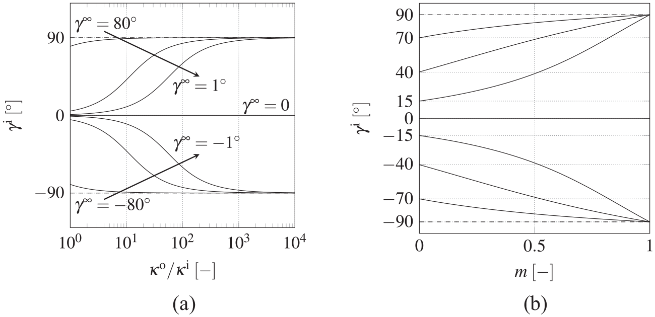
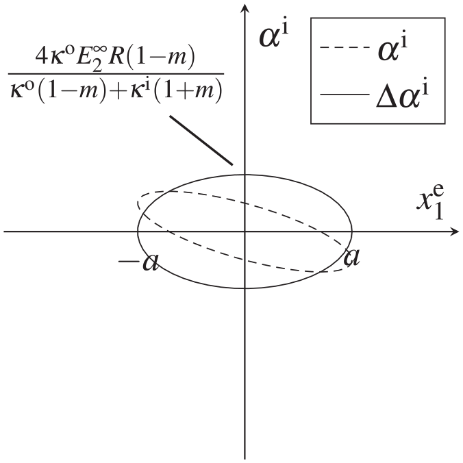
Angle of the electric field inside the ellipse
3.2. Approximate versus true surface charges and tractions
In the following, the approximate charges and tractions are understood to be results of the simple, however established, capacitor analogy model as amended according to Section 2.2.2. We define true quantities as those which emanate from the solution of the elliptic cavity outlined in Sections 2.1 and 3.1.
For further analyses of the surface charge density

where the derivative evaluates to

By means of equation (70), tangential and normal unit vectors


Accounting for the direction of
Finally, the surface tractions
While the true fields inside the ellipse as well as charges and tractions at the ellipse are given by equations (62), (63), and (73)–(75), calculation of the approximated quantities
Evaluating equation (76) at two opposite points of the ellipse symmetric with respect to the

between both points. Due to the voltage’s linear dependence on

bearing in mind that


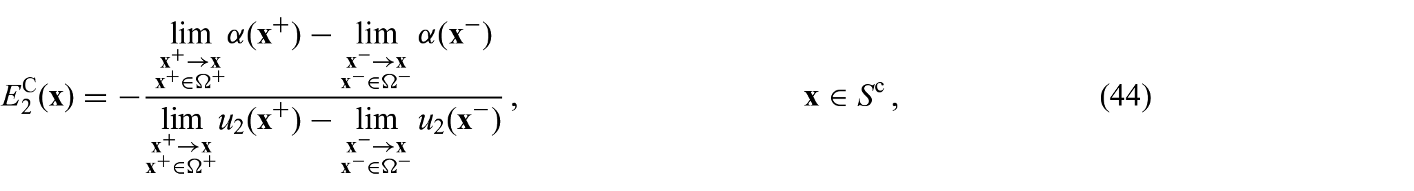
Infinite isotropic dielectric with elliptic cutout subjected to inclined electric load (
As stated beforehand, the

keeping in mind that
Beyond that, approaching conditions of a closed permeable crack for

which is appropriate for a homogeneous field
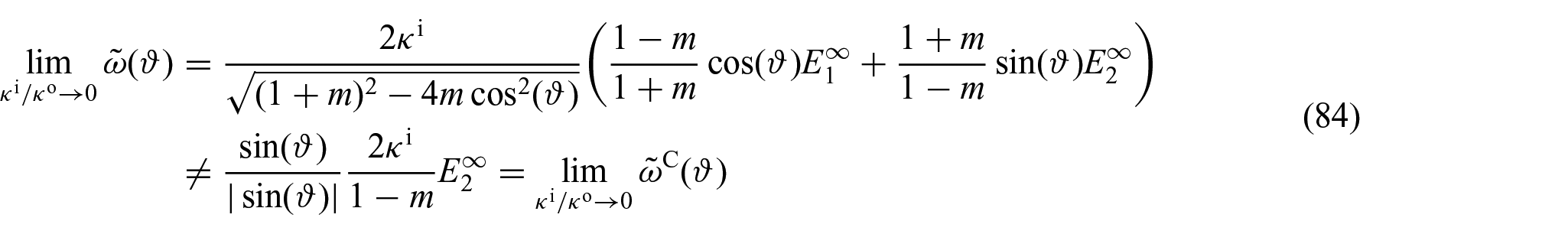
for arbitrary parameters
Infinite isotropic dielectric
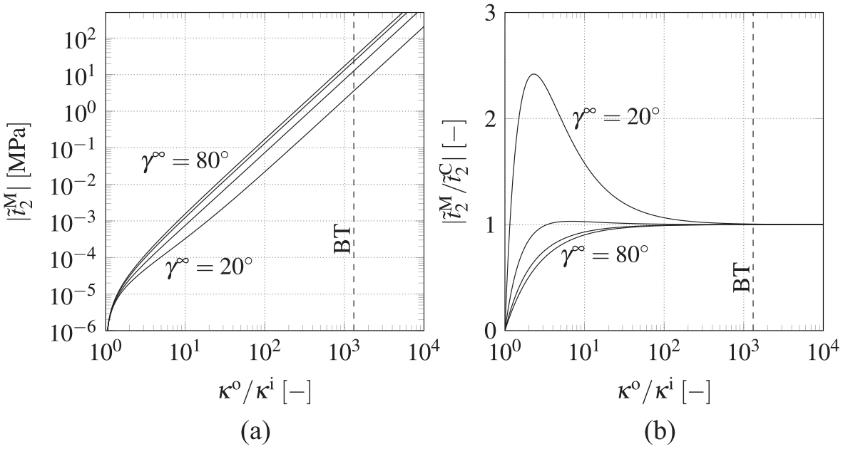
The former brings out that the ratio
The Coulombic traction

with an allocation of


First,


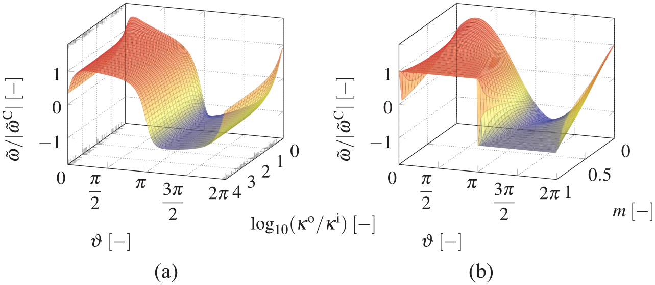
In order to estimate under which circumstances the closing effect of the Minkowski traction
Infinite cracked dielectric
On the other hand, accounting for slender ellipses with
BT exhibiting an elliptic cavity filled with vacuum
3.3. Investigation of intensity factors
In order to assess this point, consider a straight crack of length


or, equivalently,

Crack configuration accounting for a mechanically opened crack: a Griffith crack of length
with
3.3.1. Electric displacement intensity factor
The SIF and DIF for infinite dielectrics under remote mode I, II, and IV loading read [23, 31, 84]

where the superscript

where + and − refer to limit values of the upper and lower crack faces, respectively,

Parameterizing

the derivatives on the crack faces are eventually evaluated to

The normalized dielectric crack weight functions of equation (99) are plotted in Figure 11. They are unbounded near the right crack tip and tend towards zero when approaching the left crack tip. Consequently, charges close to the crack tip of interest have a much greater impact than those far from it. Furthermore,

are specified 5 so that the DIF reads
Normalized dielectric crack weight function
The integrals of equation (101) are calculated analytically, finally resulting in
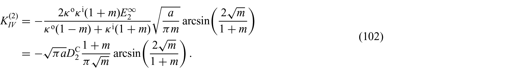
Equation (102) reveals that

In light of equation (103), the true intensity factor

Inserting the slenderness parameter
permeable crack:
semi-permeable crack:
impermeable crack:
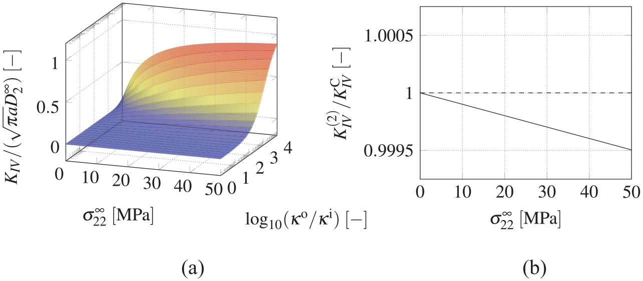
Investigation of DIFs: (a) total DIF
To begin with,
3.3.2. Stress intensity factors
Proceeding with the mechanical SIF, the contributions of the traction fields


with


Since the derivatives in the first of equation (107) and the second of equation (108) turn out constant on

Finally, collecting equation (95) and equations (105)-(109) as well as inserting
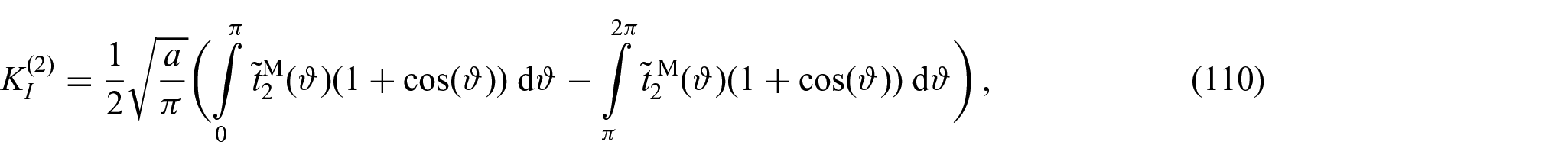
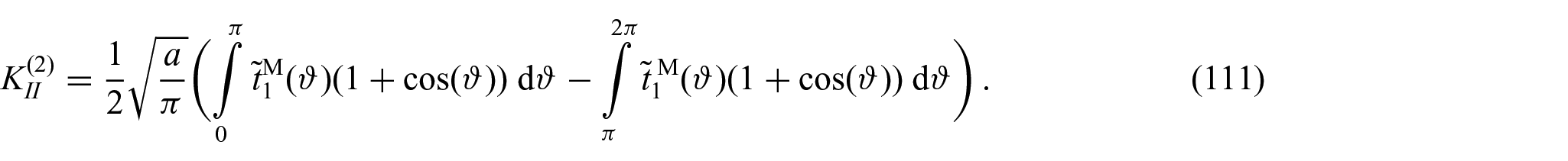
The integrals in equations (110) and (111) are calculated numerically. Vacuum and BT are chosen as inner and outer dielectric, respectively, with the results for variable
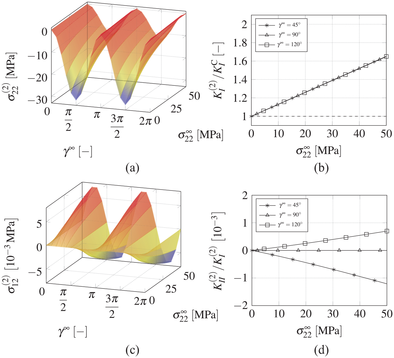
SIF for BT with
Finally, a total stress
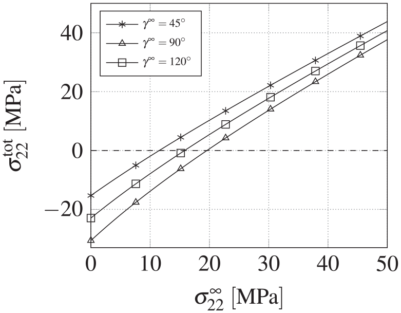
BT loaded electromechanically with
Depending on the angle of the electric load, the crack tip is under compressive load for values of
4. Conclusion
The aim of this work was to assess the electric conditions at dielectric crack faces, particularly in light of the commonly applied capacitor analogy representing an approximate model of opened crack faces and providing Neumann boundary conditions in terms of electric surface charges and Coulombic tractions. In the first instance, revisiting the electrostatic solution of an infinite linear isotropic dielectric with elliptic void subjected to remote electric fields, the deficient inverse of a conformal map involved in the transformation from an auxiliary to the physical plane has been amended by carefully examining the square root function on the complex numbers, finally granting access to solution in the entire plane. Based on this closed-form solution, the validity of the capacitor analogy was investigated, unveiling an insignificant deviation of the approximate from the true charges for small crack openings typical in brittle fracture, independent of the remaining problem parameters. As a consequence, both charges and corresponding DIF represent an appropriate substitute for their true counterparts. By contrast, the Coulombic tractions fail to properly embody the Minkowski tractions near the crack tips where the curvature is non-negligible and thus relative differences between both quantities become vast. As a result, the mode I SIF is significantly overestimated by the capacitor analogy, provided that the dielectric permittivity of the plate is much larger than that of the void, which is the case for many dielectric engineering materials. Most strikingly, the latter insight challenges the applicability of small deformation theory in fracture mechanics of dielectrics building on a closed crack in the undeformed configuration, as the electric field distribution turns out particularly sensitive to crack curvature.