
Abstract
This work presents the experimental characterization and improved model of multi-strand entangled metallic wire materials (MS-EMWMs). MS-EMWM is a novel damping material made of several strands of entangled wires using a modified manufacturing process. Six batches of specimens were fabricated and tested under quasi-static loading. Secant stiffness and loss factor were calculated to indicate the mechanical properties. The results showed that MS-EMWM has the characteristics of high damping energy dissipation compared to EMWM. A micro-multi-strand spiral spring model was proposed to predict the mechanical properties of MS-EMWM. The probability distribution of micro-spring pairs between wires was used to characterize the random combination of materials. According to the results, the improved model can effectively reflect the mechanical behavior of MS-EMWM. The mechanical properties of MS-EMWM were predicted by the coefficient matrix obtained by particle swarm optimization. Through the prediction and test results, the predicted results are acceptable.
Keywords
1. Introduction
In order to reduce the vibration and noise of industrial equipment, more and more attention has been paid to the selection and design of damping materials [1,2]. Traditional rubber materials can meet the conditions in most cases, but in the extreme environments easy to fatigue failure. Entangled metallic wire material (EMWM), which is also called metal rubber (MR), plays a vital role as a new type of damping material in reducing vibration in the harsh environment, such as high or low temperature [3,4], impact [5,6], fatigue loading cycles [7]. It has been widely applied in various fields such as aero-engines [8], electromagnetic engines [9], and equipment foundation [10].
The cause of the energy consumption mechanism of EMWM was found in some recent studies. During the loading–unloading process, the spiral wires never contact each other, to slip friction, or even squeeze state transition. When the wire is in contact, friction dissipates the loading energy, thus achieving the purpose of damping [11]. Due to the energy dissipation mechanism of traditional EMWM, its damping performance cannot be further improved under the same volume without changing the preparation process and increasing the number of metal wires in contact. Therefore, it is necessary to explore a new manufacturing process to enhance the damping energy dissipation. Generally, the metal wire used to prepare EMWM is a single-round cross-section metal wire. Hao et al. [12] tried to use non-circular cross-section special-shaped wire to prepare EMWM. The experimental results showed that it could increase the damping capacity. Hu et al. [13] proposed a new manufacturing process and prepared a new type of multi-wire metal rubber (MW-MR) composed of different metal coils and found that different coil weight ratios had a significant influence on the mechanical properties. On the basis of above researches, increasing the contact between wires can effectively improve the damping property of EMWM. In practice, it is found that the multi-strand structure inside the wire rope can effectively increase the contact between strands or wires, as shown in Figure 1. The wire rope vibration absorber also uses the way to absorb vibrations through slip friction between strands or wires [14–17]. Suppose multi-strand twisted metallic wires are used in the manufacturing of EMWM regarding the fabrication process of wire rope. In that case, the contact between wires and the energy consumption may be significantly increased. Consequently, it is an innovative approach to study the manufacturing processes and mechanical properties of multi-strand entangled metallic wire material (MS-EMWM).
The wire rope vibration absorber.
As a damping material, the displacement–force curve of EMWM shows a typical hysteresis phenomenon. Therefore, the effects of various factors on the quasi-static mechanical properties of EMWM were studied through experiments to explore its internal mechanism. Xia et al. [18] studied the influence of the direction of wires in the manufacturing process on the mechanical properties of EMWM. Li et al. [19] analyzed the effects of loading and unloading times, deformation, and ambient temperature on the static compression mechanical properties of EMWM. Mei et al. [20] explored the influence on mechanical properties of EMWM by changing the amount of precompression. By changing the loading speed, Yu et al. [21] found that the damping of EMWM decreases with the increase of the loading speed. Wang et al. [22] explored the mechanical effects of relative density of EMWM on composite sandwich structures under quasi-static conditions, showing that compressive stiffness and energy absorption effect increase with the increase in relative density. Through the above research on EMWM, density is a major factor affecting the performance of EMWM, so the loading and unloading tests of EMWM with different densities are carried out in this paper.
In order to further quantitatively describe the mechanical properties, it is necessary to establish the constitutive model. At present, the research based on the physical model mainly includes the pyramids model [23], curved beam [24], porous microelement [25], and micro-spring [26]. The pyramid model uses 10 pairs of pyramids as an analysis unit, and the pyramids are connected in series and parallel. One pyramid corresponds to one circle of coil turns, and the cone heads of each pair of pyramid pairs are opposite. During loading, the inter-turn contact process inside the EMWM is represented by the interaction of the boundary surfaces. The curved beam model replaces a single turn with a quarter-circle arc. One end of the curved beam is fixed, and the other end is loaded, which represents the stress of the EMWM unit. Since there are pores inside EMWM, a porous microelement is proposed. The interior of EMWM is divided into cube units connected by simply supported beams, and the deformation of simply supported beams is analyzed. The micro-spring model is the most widely used model, because EMWM is made of helical coils, and its geometry is most similar to the micro-spring. Due to the disorder of the internal wire arrangement, it is not unidirectional when loaded, so the radial and axial stress of the micro-spring is analyzed. In summary, the micro-spring model is used as a force analysis unit in this paper. Due to the special geometry of the multi-strand wires, the micro-spring model is improved.
Based on these studies, the micro-spring model could be used to describe the mechanical model of MS-EMWM combined with the quasi-static mechanical tests. Therefore, the aim of this study is to compare the difference of mechanical properties between EMWM and MS-EMWM and develop an improved model able to reflect the mechanical behavior of MS-EMWM.
2. MS-EMWM specimens
2.1. Manufacturing process of MS-EMWM
The manufacturing process of traditional EMWM mainly includes metal wire selection, pre-form spiral coil, entangled wire mesh, compressive formation, and so on. Unlike traditional EMWM, MS-EMWM is made of more than one strand of metal wire, which is twisted by metal wire concerning the manufacturing process of wire rope and multi-strand spiral spring. The fabrication process of MS-EMWM consists of a new step, which is the manufacture of multi-strand wires. Other processes such as pre-form spiral coil, entangled wire mesh are the same as the traditional ones. The schematic diagram of the manufacturing process of MS-EMWM is shown in Figure 2.
Manufacturing process of MS-EMWM.
The multi-strand wires were made into spiral coils by semi-automatic winding equipment. Semi-automatic spiral winding equipment was mainly composed of the mandrel, pressure plate, guide wheel, and so on. One end of the mandrel was fixed in the clamping end device driven by the speed regulating motor. The multi-strand wire was sent to the mandrel through the guide wheel, compacted by the pressure plate, and wound into a multi-strand twisted turn spiral coil. Finally, the formed spiral coil could be detached from the mandrel. According to the above process, the spiral coils made by the twisted multi-strand metal wire and the ordinary metal wire are shown in Figure 3.
Single-strand and multi-strand spiral coils.
The spiral coils were made into entangled wire mesh through the numerical control blank winding equipment. As the process described above, the conventional EMWM with single-strand wire spiral coils and MS-EMWM with seven-strand wire spiral coils were produced. Figure 4 shows EMWM and MS-EMWM specimens and Scanning Electron Microscopy (SEM) views.
Specimens (a) EMWM and (b) MS-EMWM.
2.2. Characterization of MS-EMWM
Three batches of EMWM and three batches of MS-EMWM were prepared using the above procedure. The specimen is a solid cylindrical shape with a diameter of 24 mm and a height of 14 mm. Due to preparation errors, there may be some deviations in the dimensions of the prepared specimen. The mechanical properties of EMWM strongly depend upon the density [26]. The same dimensions of the specimens can be ensured by controlling the pressure of the compressive formation. And each batch was composed of three specimens. The diameter, height, mass, density, number of wire strands of each specimen are listed in Table 1.
Structure parameters of MS-EMWM specimens.
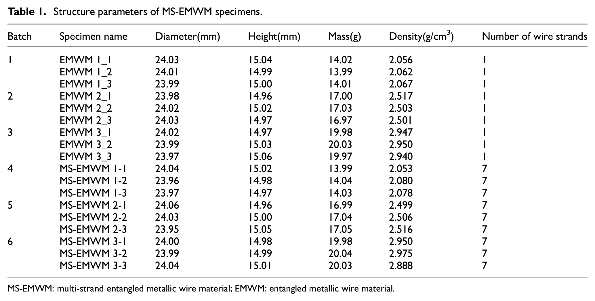
MS-EMWM: multi-strand entangled metallic wire material; EMWM: entangled metallic wire material.
3. Experimental methods and results discussion
3.1. Tests results and discussion
Once force–displacement curves were found, the secant stiffness and loss factor can be derived from the experiment data. The sketch of the hysteresis loop under loading–unloading compression is depicted in Figure 5. A clear difference of loading and unloading force curves has been observed in all experiments performed in this work, which can reflect the energy-dissipation property of EMWM/MS-EMWM. The reason for this is that because of the sliding friction between wires.
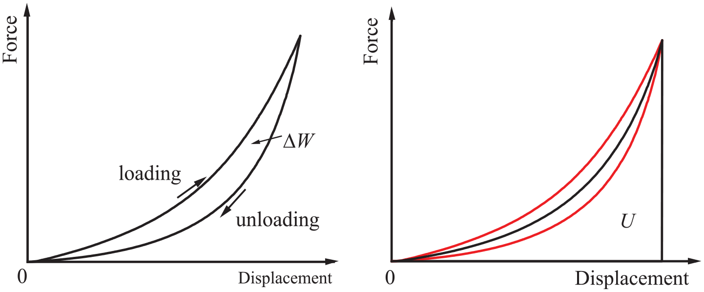
Sketch of the hysteresis loop.
Under external forces, the metal wires connected in EMWM/MS-EMWM cause relative slippage in the contact area. Part of the mechanical energy is converted into internal energy consumption in the form of dry friction. W is the area below the loading curves, representing the maximum deformation energy stored in one cycle. ΔW is the area between the loading curves and unloading curves, which means the dissipated energy. The maximum elastic potential energy U and loss factor η [27–29] are defined, respectively, by equations (1) and (2) as shown below:


In engineering practice, it is often necessary to know the bearing capacity of materials. Secant stiffness is usually used as the evaluation index of bearing capacity (see Figure 6), which can be calculated as follows.

where Fmax and Fmin, respectively, represent the maximum and minimum forces in a loading and unloading cycle, and xmax and xmin, respectively, represent the maximum and minimum displacement in a loading and unloading cycle.
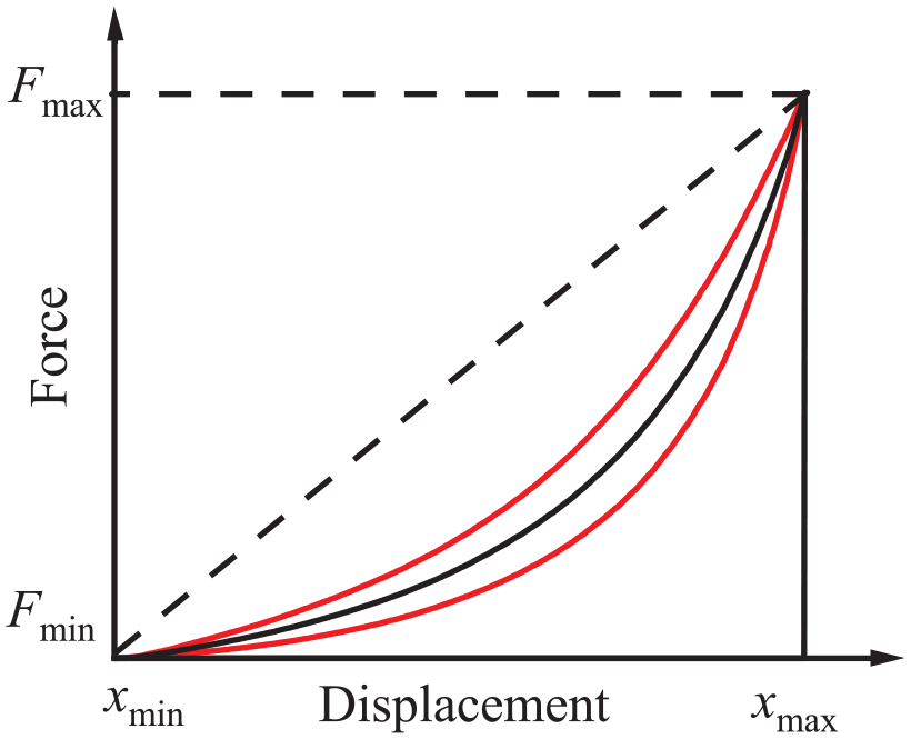
Sketch of secant stiffness.
3.2. Experimental methods
Quasi-static mechanical compression tests were conducted using a WDW-T200 electronic universal testing machine, as indicated in Figure 7, to investigate the mechanical properties of MS-EMWM. The arrow indicates the loading direction. Typical hysteretic loops from the tests of MS-EMWM 3-1 are shown in Figure 7. Among the curves, the first cycle is quite different from the others. This phenomenon is mainly due to the non-slippery surface of the specimen and the lack of close contact with the pressure plate for the first time in the quasi-static mechanical compression tests.
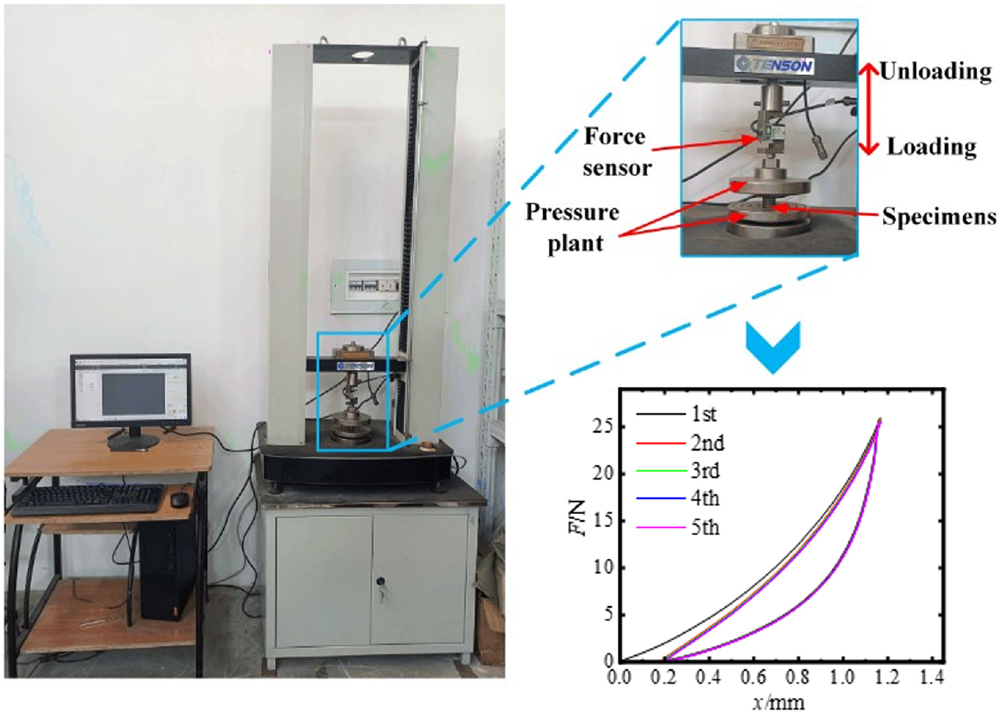
Equipment of quasi-static mechanical compression tests.
There is little difference in the last four hysteresis loops, which demonstrates that the mechanical properties of MS-EMWM tend to be stable after one loading–unloading process. In this paper, the fifth force–displacement curves were used to evaluate mechanical properties. The tests were conducted under displacement-control mode. And the loading speed was controlled at 1 mm/min. To guarantee tight contact between specimens and pressure plant, a 1 N pre-compression is applied to each sample.
4. Improved model of MS-EMWM
The basic unit of MS-EMWM is multi-strand metal wire spiral coils, which are entangled with each other. The contact between spiral coils and wires is assumed with sticking contact and sliding contact. In particular, the sliding friction between wires contributes to energy dissipation.
4.1. Stiffness of the helix cell
The micro-element of MS-EMWM can be described as a micro-multi-strand spiral spring, which is composed of a spiral coil turn elastic element at a certain angle to the direction of the load. The micro-multi-strand spiral spring can represent the elastic characteristics of the spiral coil when suffering stress.
The elasticity and frictional property of the spiral coil during the loading process can be characterized by the micro-multi-strand spiral spring, as shown in Figure 8, where ψ represents the spiral angle of the spring, while β represents the twisting angle of multiple strands, d represents the diameter of a single wire, and m represents the number of wire strands.
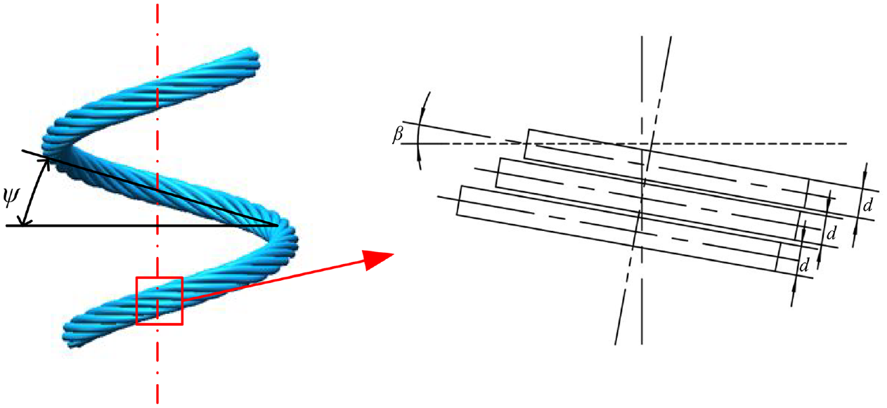
Schematic diagram of micro-multi-strand spiral spring.
It is assumed that when the micro-multi-strand spiral spring is under loading, the contact between wires is not tight. Each strand of wire deforms independently and does not interfere with each other [30–32]. When conducting the primary analyses, the micro-multi-strand helical spring is equivalent to m single-strand springs in parallel. The twisting angle β of multi-strands is generally 15°∼35°, while the spiral angle of multi-strands of metal wires is 6°∼9°. Obviously, the spiral angle is smaller than the twist angle, so the effect of the helix angle can be ignored in the analysis. Supposing that in the deformation process, the spring remains helical, then each strand of wire in the micro-multi-strand spiral spring is equivalent to a spiral spring.
When the micro-multi-strand spiral spring is subjected to axial load Fz, the force condition is presented in Figure 9. There are axial force Fz and torque Tt on the oblique section cut by plane V of the spring axis. The plane V′ is perpendicular to the center of the strand and forms a β angle with the plane V. The cross-section A of the strand is taken in the plane V′, the axial direction of the strand is taken as the t-axis, the intersection line between the plane V and the plane V′ is the n-axis, and the axis perpendicular to the n-axis and t-axis through the plane V′ is the b-axis. At section A, the axial force Fz and torque Tt can be decomposed into several parts [33].
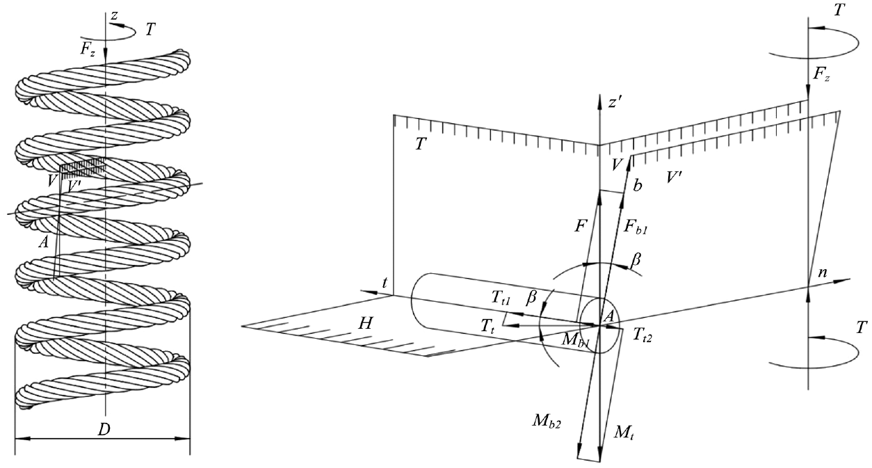
Analysis of micro-multi-strand spiral spring under axial load.
Tt 1 represents the torque around t-axis and is given as follows:

Mb 1 represents the bending moment around the b-axis and is given as follows:

Ft 1 represents the normal force along the t-axis and is given as follows:

In the analysis, the wire can be considered as a slender rod. Therefore, the contribution of shear force to the deformation energy is minimal and can be ignored.
The deformation ΔZ of the spring along the load direction is obtained from Castigliano’s theorem as follows:
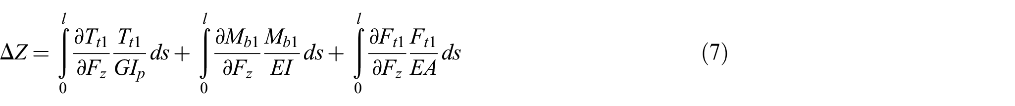
where ds represents the micro-segment, ds = Ddθ/2cosβ; θ represents the polar angle, and the range is (0, 2π); the cross-sectional area A = πd2/4; the cross-sectional moment of inertia I = πd4/64; the cross-sectional polar moment of inertia Ip = πd4/32; the shear modulus G = E/2(1 + ν), E denotes Young’s modulus, ν means Poisson’s ratio.
By integrating equation (7), the deformation of micro-multi-strand helical spring along the axis is obtained as:

Furthermore, the stiffness of axial deformation can be expressed as:

When the micro-multi-strand spiral spring is subjected to the radial load Fr, the force condition is shown in Figure 10. When the spring is subjected to a radial load, the spring produces radial deformation. On the cross-section of the micro-multi-strand spiral spring at the end of the loading, there are bending moment M = Frζ and radial force Fr, which can also be decomposed into several parts as follows.
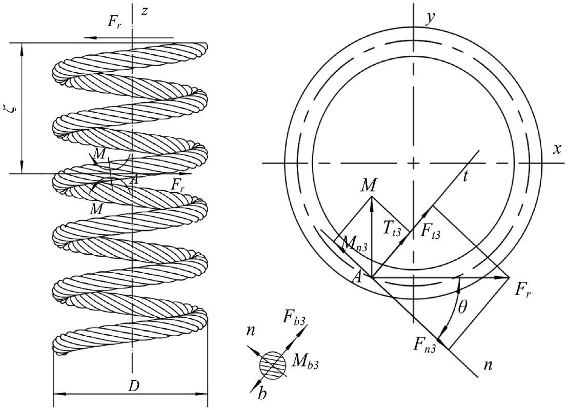
Analysis of micro-multi-strand spiral spring under radial load.
Tt 3 represents the torque around t-axis and is given as follows:

Mb 3 represents the bending moment around the b-axis and is given as follows:

Mn 3 represents the bending moment around the n-axis and is given as follows:

Ft 3 represents the normal force along the t-axis and is given as follows:

Similar to the analysis in equation (7), the deformation ΔR of the spring along the direction of radial is obtained from the Castigliano’s theorem as follows:
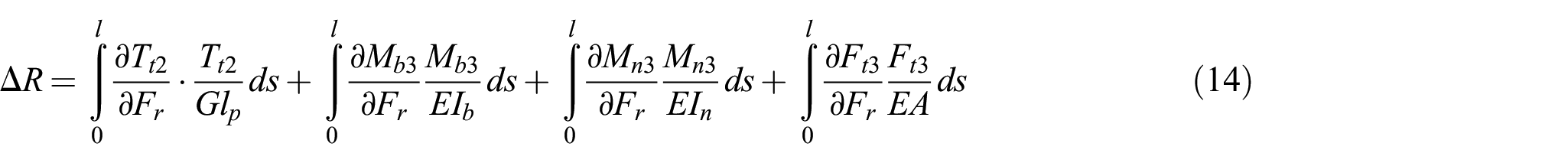
where the distance is ζ = πDtanβ/2, and the moment of inertia of the cross-section is Ib = In = πd4/64.
By integrating equation (14) in the range of polar angle (0,π), the radial deformation of micro-multi-strand helical spring along the axis is obtained as follows:

Furthermore, the stiffness of radial deformation can be expressed as follows:

4.2. Analysis in different contact states
The MS-EMWM has a porous structure as shown in Figure 4. Due to MS-EMWM being made of multi-strand twisted wires, the contact between the wires is mainly linear. Compared with EMWM, the basic microelement of MS-EMWM is a multi-strand spiral spring, and the contact between wire and wire can be regarded as always in contact with each other. Therefore, there are two kinds of contact states between the spiral coils and between the strands: slip contact and extrusion contact.
Figure 11 shows a schematic diagram of the force acting on the micro-spring element in the state of sliding contact. The spiral coils subjected to axial and radial loads are in contact [26]. When the tangential force between the strands exceeds the maximum static friction, slippage occurs between the wires. The upper helix slips along the lower helix, and the interaction between the contact spiral coils can be simplified to normal pressure N and sliding friction f.
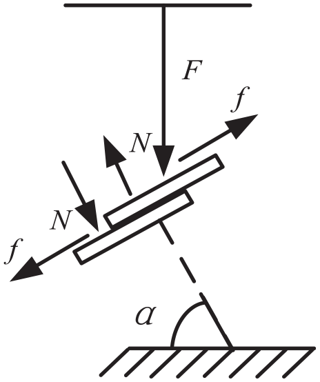
Force profile of sliding contact state.
The positive pressure N and the sliding friction force f satisfy the Coulomb friction law, f = μN. Through the analysis, the force balance equation can be obtained as follows:

where μ represents the friction coefficient of the wire and α represents the average contact angle. The average contact angle is related to the entangled angle φ and compression ratio i during the preparation of the blank, which can be approximately seen as a proportional relationship and is given as follows:

Thus, the following conclusions can be acquired:

Finally, substituting equation (17) into equation (19), we get:

Stiffness can be expressed as:

When the two spiral coils and wires in contact with each other slip a certain displacement, they reach the slip limit [13]. There is no slip space, and the contact state becomes extruded contact, as shown in Figure 12.
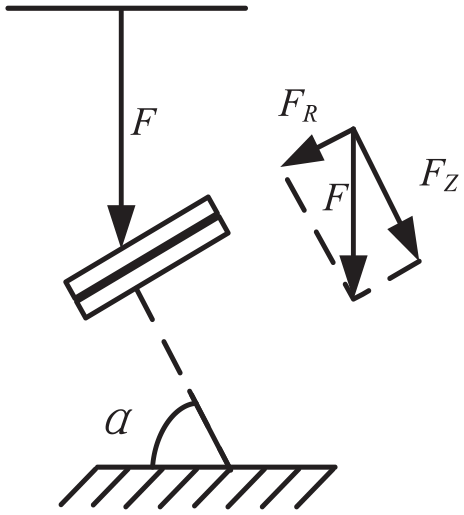
Force profile of sliding extruded contact.
The force analysis of the contact pair in the extruded state can be obtained as follows:

The deformation of the micro-spring in the extruded state is given by:

After substituting equation (22) into equation (23), the stiffness of the extrusion contact state can be expressed as:

4.3. Poisson distribution of contact states in MS-EMWM
In the interior of MS-EMWM, microelements in different contact states exist at the same time. The mechanical properties of microelements in different contact states are other based on the above analysis. The changes in contact states follow the deformation of MS-EMWM.
Because MS-EMWM is formed by stamping under pressing, the number of internal microelements is also determined as the material parameters are determined. If the density of MR is ρ, the density of wire is ρs, and the relative density ρr = ρ/ρs, the total number of microelements per unit volume N0 can be expressed as follows [34]:

In the process of loading/unloading, it is assumed that the distribution of various contact states in MS-EMWM can be regarded as conforming to a Poisson distribution [35]. The relationship between the number of contact pairs per unit volume and all contact pairs in MS-EMWM is indicated by equation (26) as follows:

where ni represents the number of metal wires in unit volume slip/extrusion contact state, ni represents the number of all contact pairs, λ is the structural parameter, and ε is the directional strain.
According to the above comprehensive analysis, macro-phenomenological improved model of the MS-EMWM for loading cases can be obtained as follows [36]:

where
In the unloading state, the distribution of the number of contact pairs per unit volume of MS-EMWM components in different contact states can be expressed as equation (28):

Improved model of the MS-EMWM for unloading cases is shown by the following formula:

where
5. Results and discussions
5.1. Test results
The force–displacement curves of specimens that belong to different batches at 1 mm displacement are shown in Figure 13.
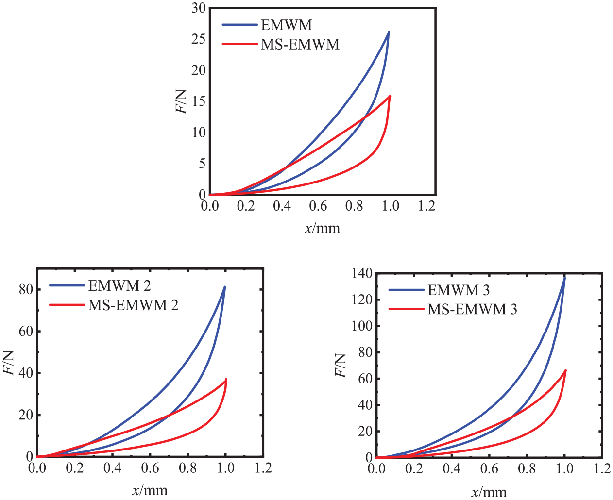
Hysteretic loops of each specimen.
The mechanical properties of each sample can be obtained by equations (2) and (3). Moreover, the mean and standard deviation of secant stiffness and loss factor of six batches are listed in Table 2. Due to the measured noise and complex manufacturing process, the error is inevitable. The statistical method was used to reduce the effect of measuring and manufacturing errors. From Table 2, it can be seen that the maximum standard deviation of loss factor is 0.009237, and the maximum standard deviation of secant stiffness is 9.166. The results show that each batch has a good consistency.
Mechanical properties of specimens.
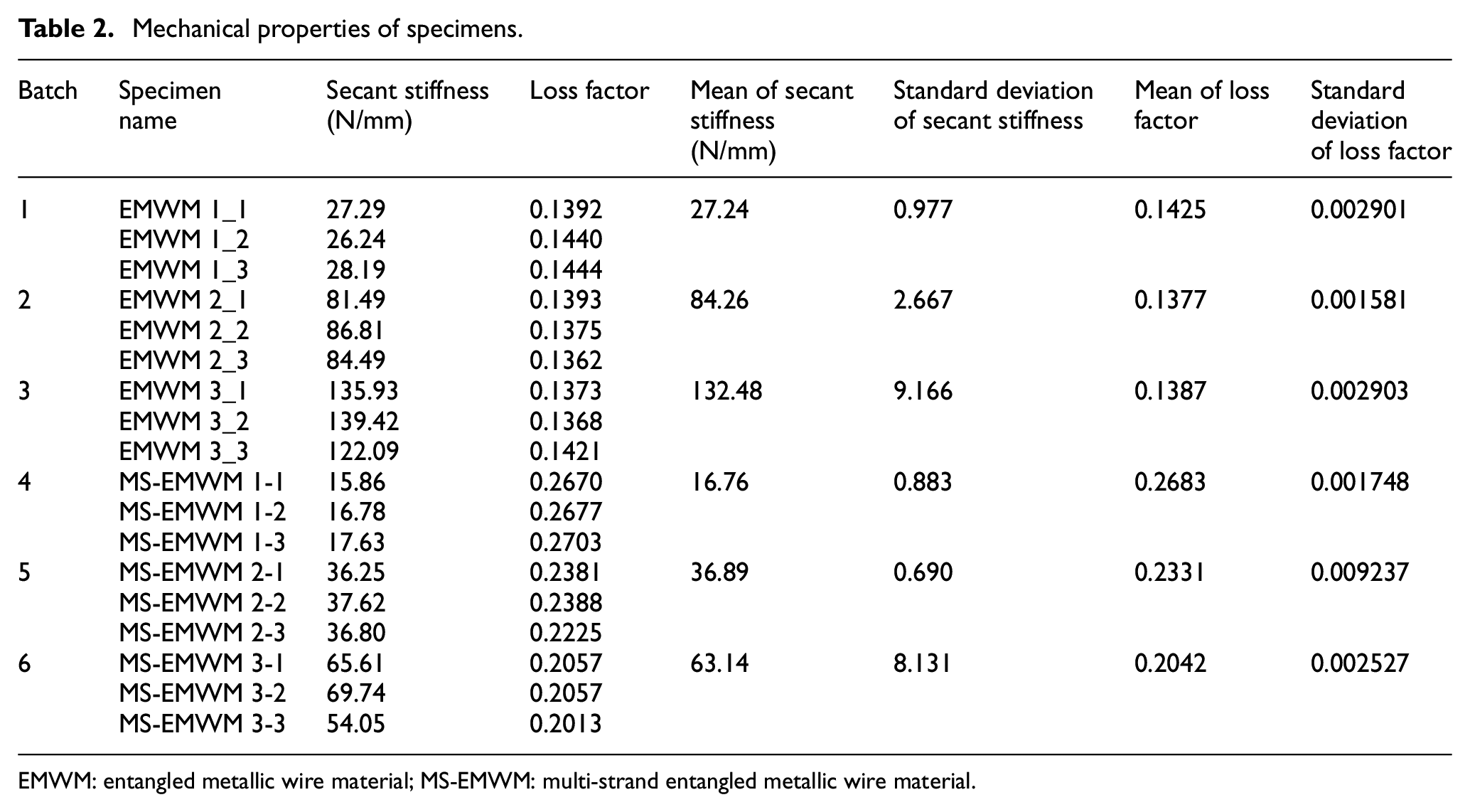
EMWM: entangled metallic wire material; MS-EMWM: multi-strand entangled metallic wire material.
Figure 14 shows the mean loss factor and the mean secant stiffness of different batches. With the increase of density, the secant stiffness of EMWM and MS-EMWM increases. The secant stiffness of EMWM varies from 27.24 ± 0.977 N/mm to 132.48 ± 9.166 N/mm. Meanwhile, the secant stiffness of MS-EMWM varies from 16.76 ± 0.883 N/mm to 63.14 ± 8.131 N/mm. At the same density, EMWM has a higher secant stiffness than MS-EMWM. Opposite to the secant stiffness, the loss factor decreases with increasing density. The loss factor of MS-EMWM is 30% higher than that of EMWM at the same density. Taken together, it is evident that MS-EMWM has the advantages of low stiffness and weak bearing capacity but a higher energy dissipation ability in comparison to EMWM.
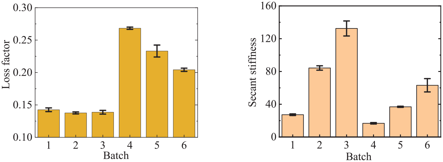
Mechanical properties of different specimens: (a) loss factor and (b) secant stiffness.
The smaller secant stiffness and the larger loss factor are mainly due to the different internal complex micro-structure and different contact distribution between the wires. As can be seen from the SEM view of EMWM shown in Figure 4, the contact states between the wires of EMWM is point contact state. A small part of wires is contacted in the state of line contact. There are three contact states between the wires: non-contact state, slip contact state, and extrusion contact state. MS-EMWM are formed by multi-strand twisted wires. The internal wires are mainly in the states of line contact. And the contact states between the spiral coils of the internal multi-strand twisted wires are similar to that of the single-strand spiral coil of EMWM, which is mainly point contact. The main contact state between wires of MS-EMWM are slip contact and extrusion contact. The number of contact pairs involved in friction between multi-strand twisted wires is obviously higher than that of single wires. The contact state is mainly line contact with larger contact area. The slip friction will cause more energy consumption. The damping effect of MS-EMWM is better than that of EMWM. Through the observation of SEM, it is obvious that the number of multi-strand twisted wire spiral coils per unit volume of MS-EMWM is less than that of EMWM. It means that the number of contact points between multi-strand twisted wire spiral coils decrease. Therefore, MS-EMWM has smaller bearing capacity and higher energy consumption characteristics.
5.2. Model verification
Equations (27) and (29) have obtained the macro-phenomenological improved model of the MS-EMWM. However, due to the complex arrangement of metal wires, the form of internal contact and the number of contact pairs under various contact conditions cannot be directly observed and predicted. Therefore, the particle swarm optimization (PSO) algorithm with high precision and fast convergence speed is used to identify and modify the structural parameters in the model.
PSO simulates the optimization process as the process of birds searching for food. The optimization principle is that in an n-dimensional space, several particles constitute a population. Each particle will constantly adjust its own speed and position according to its and other particle position information and constantly update the optimal local solution of each particle and the optimal global solution of the whole population. Each particle in the algorithm will approach a point to find the optimal solution to the problem [37,38]. In this paper, the maximum moving speed of the particle is 10, the particle size is 50, and the learning factor is 1.5. The objective function of PSO is the sum of squared error (SSE), as shown below:

where
By bringing the parameters in Table 3 into the improved model and identifying and modifying the undetermined parameters (
Physical parameters of the model.

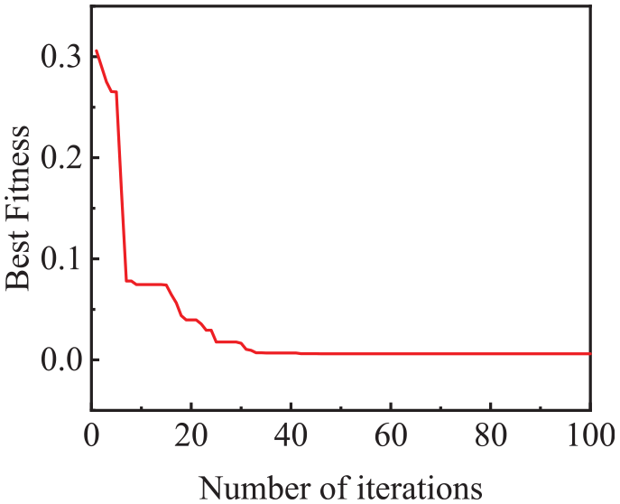
Process of PSO.
Through F =σA, x =εL, the stress–strain relationship was transformed into the force–displacement relationship. The hysteretic loops of the test and the improved model identified and modified by PSO algorithm with different relative densities of MS-EMWM are shown in Figure 16.
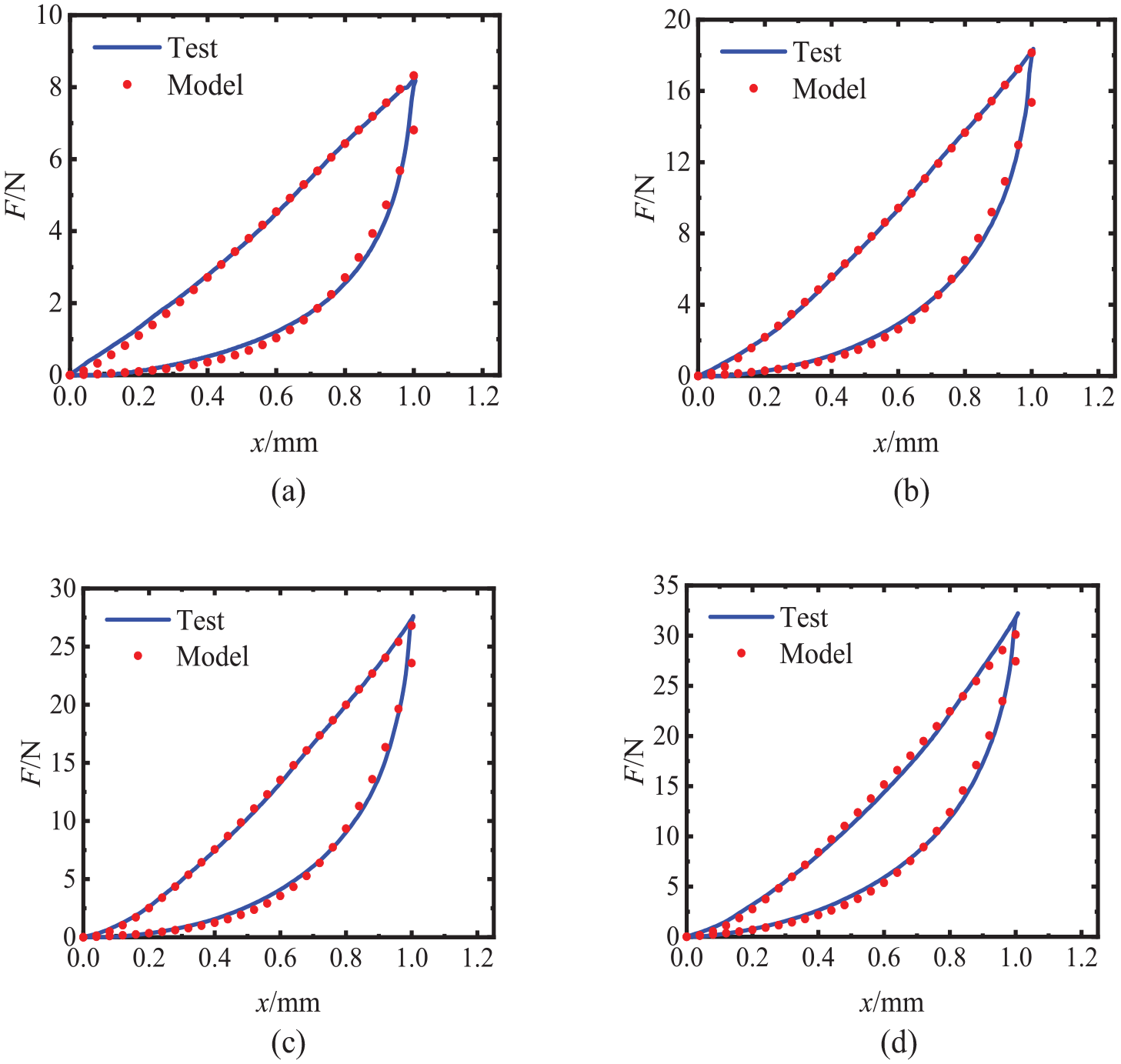
Hysteretic loops of the MS-EMWM samples with different densities: (a) ρr = 0.25, (b) ρr = 0.28, (c) ρr = 0.30, and(d) ρr = 0.33.
It is possible to observe from Table 4 that the deviation of loss factor between the model and the test is all less than 3%, and the static stiffness deviation is less than 6%, which proves that the improved model can well explain the energy dissipation characteristics of MS-EMWM.
The deviation of loss factor/secant stiffness between test and model.
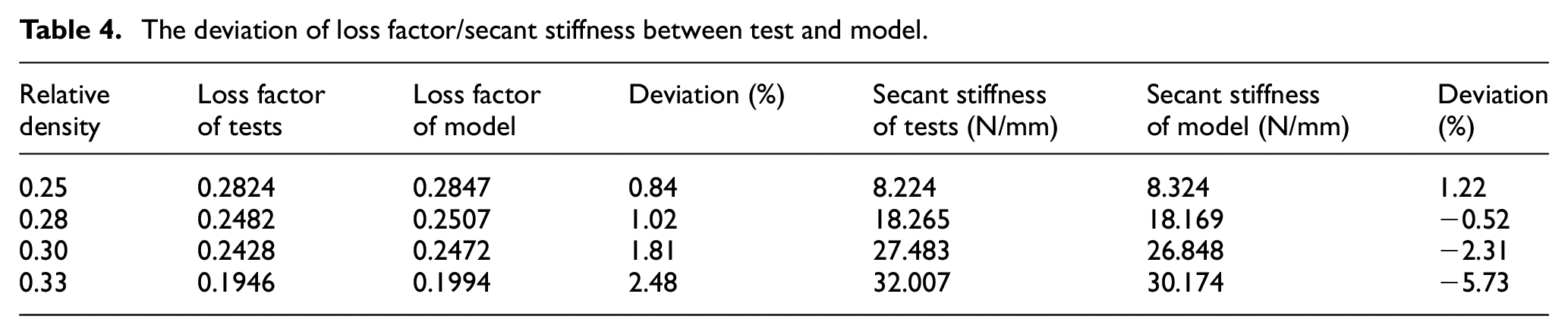
It is evident from Table 4 and Figure 16 that the predicted results of the model are consistent with the experimental data, which can reflect the characteristics and mechanical properties of MS-EMWM in a loading/unloading regime.
The following regression analysis method can be used to predict the correction coefficient in the model:
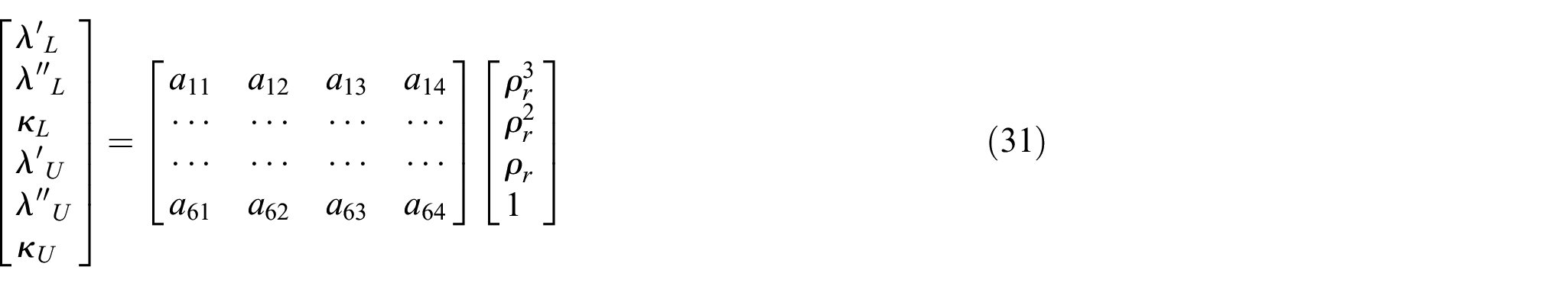
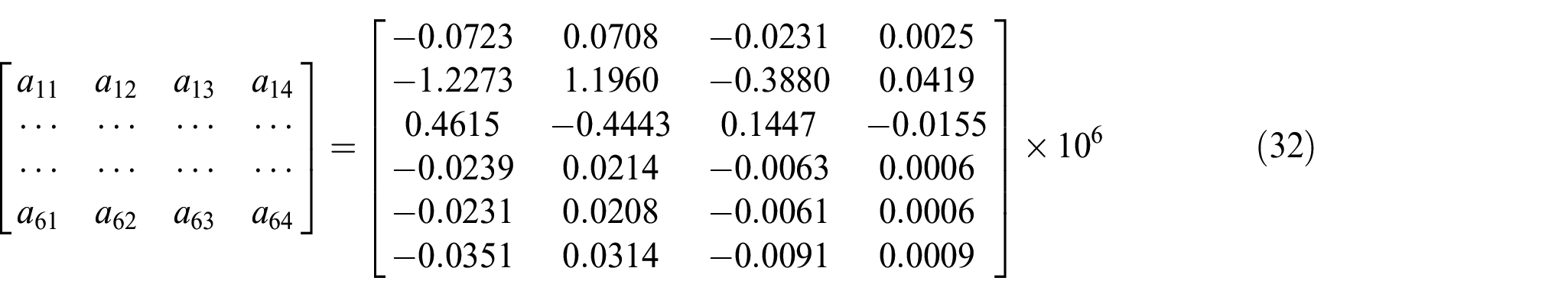
The parameters of the regression model were chosen with the least squares method according to equation (31). The value of the model coefficient matrix is as given by equation (32). The curve of the parameters in the model varying with the relative density can be obtained as shown in Figure 17.
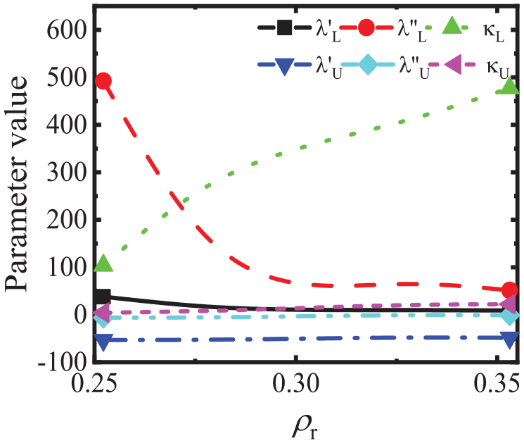
The curves of coefficients fitted by the linear least squares method.
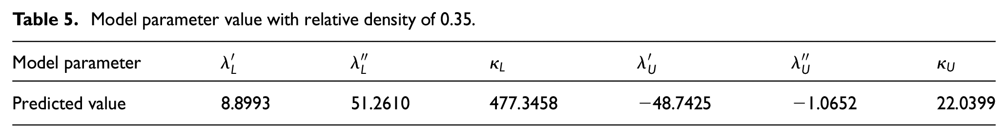
To verify the accuracy of the predicted data of this model, the MS-EMWM specimens with a relative density of 0.35 were prepared by the same process. The corresponding parameter values were found according to the curve (see Figure 17), as shown in Table 5.
Model parameter value with relative density of 0.35.
The model parameters in Table 5 were substituted into equations (27) and (29). The loading and unloading curves of model prediction and test are as shown in Figure 18.
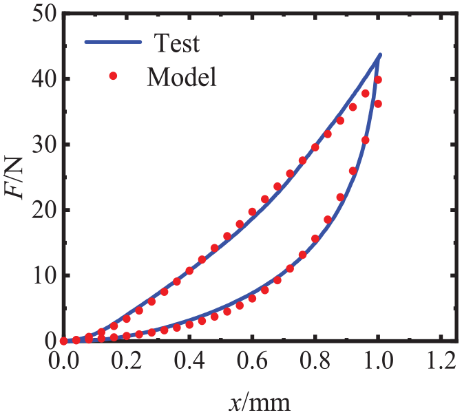
Hysteretic loops of the MS-EMWM samples (ρr = 0.35)
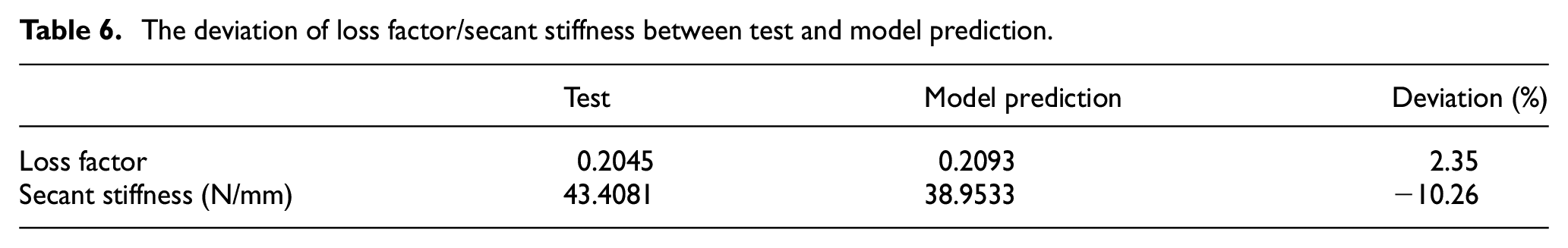
As can be seen from Figure 18, model prediction and test data basically coincide. The results of loss factor and secant stiffness are shown in Table 6. As can be seen from Table 6, the deviation of loss factor is 2.35% and that of secant stiffness is 10.26%. Although there has been an increase in deviation compared to low-density MS-EMWM, it remains within an acceptable range overall. Therefore, the model can also predict the mechanical properties of MS-EMWM at different densities well.
The deviation of loss factor/secant stiffness between test and model prediction.
6. Conclusion
In this study, multi-strand entangled metallic wire material (MS-EMWM) was developed as a new damping material made from several strands of wires using a modified classical manufacturing process. In addition, the improved model of MS-EMWM was established combined with the tests. To summarize, the following main conclusions can be drawn:
Quasi-static mechanical tests were carried out on six batches of EMWM and MS-EMWM. The results showed that the mechanical properties of MS-EMWM had characteristics of high energy consumption and low bearing capacity compared with EMWM. As the density increases, the loss factor decreases, the secant stiffness increases.
Combined with SEM observations, an improved model based on micro-multi-strand spiral spring was established by using PSO, in which Poisson distribution was constructed to represent the random spatial distribution of wires. Finally, the mechanical properties of MS-EMWM were predicted by the improved model. The results suggest that the model can reflect the changing trend of quasi-static mechanical properties of MS-EMWM, and it has good predictive results. The study of this paper would provide some reference for the research of entangled metallic wire materials with better damping properties in the future.
Footnotes
Author contributions
Y.T. contributed to the conceptualization, methodology, data curation, writing—original draft preparation, and software. B.Z. contributed to the conceptualization, methodology, writing—reviewing and editing, and software. Y.W. was involved in the conceptualization, methodology, validation, writing—reviewing and editing. H.B. and R.L. contributed to the methodology, writing—reviewing and editing.
Declaration of conflicting interests
The author(s) declared no potential conflicts of interest with respect to the research, authorship, and/or publication of this article.
Funding
The author(s) disclosed receipt of the following financial support for the research, authorship, and/or publication of this article: This research was supported by National Natural Science Foundation of China (grant no. 12002088).
Data availability statement
The data that support the findings of this research are available from the corresponding author upon reasonable request.