
Abstract
Curved structures have enabled masons, engineers, and architects to carry heavy loads and cover large spans with the use of low-tensile strength materials for centuries, while creating the marvels of the world’s architectural heritage. Despite the long history of these practices, finding optimal structural forms and assessing the stability and safety of curved structures remains as topical as ever. This is due to an increasing interest to preserve heritage structures and reduce material use in construction, while replacing steel and concrete with low-carbon natural materials. The analogy between inverted hanging chains and the optimal shape of masonry arches is a concept deeply rooted in our structural analysis practices. The paper revisits the equilibrium of the hanging chain, following the transition from Newtonian to Lagrangian Mechanics. Understanding these ideas reveals that hanging chains and arches are two incompatible structural systems. The paper discusses the limitations of describing the equilibrium of two-dimensional objects with finite thickness (e.g., arches) by using one-dimensional objects of infinitesimal thickness (e.g., hanging chains, funicular lines) on the geometry of the curved structure and the loading conditions that can be assumed in practice. These limitations manifest themselves by applying force equilibrium that carefully considers the stereotomy exercised, which becomes particularly critical when studying the stability of vertical sections or considering seismic loads. The paper shows that by taking the logical progression towards Lagrangian Mechanics, one may obtain rigorous solutions for the limit equilibrium state of curved structures by applying the principle of stationary action. This approach liberates the analyst from the need to consider equilibrium of each individual block or describing geometrically the load path of thrust forces.
Keywords
1. Introduction
The building and construction sector accounts for the 39% of CO2 global emissions, with 11% corresponding to construction materials manufacturing [1]. Hence, achieving climate neutrality requires radical reduction of material and energy use in construction, while improving maintenance and performance of existing structures.
Over the last years, there has been an increasing interest by architects and structural engineers in “Curved Architecture” optimal design and construction [2–5], which is being enhanced with modern manufacturing, automated construction, and robotics [6–8], as well as in the assessment and life-cycle management of existing masonry arch structures, such as historic buildings and ageing infrastructure [9,10].
Curved structures, such as arches, vaults, domes, and shells, have the advantage of developing mainly compressive stresses. This has allowed, since the invention of the masonry arch in ancient Mesopotamia, to build sustainable structural systems that lasted for centuries with the use of low-tensile strength materials. These materials, such as stones, bricks, and mortar, were usually obtained from natural sources available in close distance from the construction site. Furthermore, compressive curved structures require limited or no reinforcement with high-tensile strength materials, such as steel, while discontinuous blocky systems, such as masonry, do not necessarily require heavy lifting cranes during construction. As a result, the use of natural, light, low carbon/energy materials has been a common practice for centuries as energy was not abundant, which gradually changed after the industrial revolution. Due to the resource and energy depletion challenges of the recent years, however, rethinking structural design inspired by these long-established practices is a necessity, rather than an option.
Finding the optimal form of curved structures, like masonry arches, to ensure safety and reduce construction material, has been at the forefront of Structural Mechanics for centuries and has been associated with the equilibrium of the catenary and hanging chains at least since the published work of Hooke [11]. Today, many form-finding algorithms (e.g., Andreu et al. [12], O’Dwyer [13], and Block [14], and rich literature following these pioneering works) combine principles of Graphic Statics [15,16] with modern computer coding, and have achieved user-friendly visualisations to describe the equilibrium of complex curved structures. These tools appear particularly useful for architectural design applications, due to the directness and simplicity that have been inherited from Graphic Statics.
This paper explains that, during the transition from Graphic Statics to relevant modern form-finding algorithms and structural assessment tools, there have been several subtle concepts that have remained obscured to the wider construction community. The main source of these inconsistencies, as discussed in this paper, is the adoption of one-dimensional elements to explain the equilibrium of two-dimensional structures, together with the simplification of disregarding the stereotomy exercised. The paper explains that these inconsistencies do not lead to significant errors for special cases when only gravity loads and certain imminent collapse mechanisms are assumed, and when equilibrium of relatively flat structures is considered. However, in view of applying optimal design tools in practice for studying a wider range of structural forms, orientations, and imminent collapse mechanics, and make use of building codes that impose a variety of loading conditions beyond gravity loads (e.g., seismic, wind), being consistent with force equilibrium by considering the stereotomy exercised is essential.
The paper goes beyond the application of vector analysis and follows the transition in Science from Newtonian to Lagrangian Mechanics that has occurred over the last three centuries. The following section, Section 2, discusses this transition by tracking the evolution of the catenary problem, which has been to find the true form of the hanging chain, ranging from simple force equilibrium to the development of stationary potential energy statement. An in-depth understanding of the hanging chain problem is critical, as one may realise that inverted hanging chains and arches are two incompatible structural systems, as shown in Section 3. Note that the idea of inverting the shape that one-dimensional objects obtain in equilibrium to analyse the equilibrium of two-dimensional objects has been deeply rooted in our practices, and Section 3 further discusses the limitations of such simplification. Following again the transition from Newtonian to Lagrangian Mechanics, Section 4 proposes the use of the principle of stationary potential energy as a powerful and simple tool to obtain rigorous solutions for the limit equilibrium state of curved structures without the need to describe geometrically the load path of forces or apply equilibrium in each individual block. Conclusions are summarised in Section 5.
2. Newtonian and stationary-action formalism to derive the catenary
2.1. Geometric formalism—static equilibrium
The catenary refers to the shape of a hanging chain or string of uniform linear mass density, infinite axial stiffness, zero bending stiffness, and infinitesimal thickness, which is subjected to a uniform gravitational field. It assumes the form described by the hyperbolic cosine function. Modern calculus textbooks derive the catenary expression by following either a Newtonian (force equilibrium) [17] or a Lagrangian (variational calculus) [18] formalism.
Finding the true form of the catenary is a classical problem of mechanics and has been a subject of a lively debate among scholars since Galileo’s time. The first attempts that lead to the correct form of the catenary were published in Acta Eruditorum by Leibniz et al. [19] after a challenge posed in the same journal by Jacob Bernoulli a year before [20]. It is pointed out that Jacob Bernoulli did not impose a restriction that the hanging chain should be inextensible, which is assumed in those three solutions, as he was in search for a broader family of curves that extensible strings may form [21].
Applying force equilibrium is evident in the solution offered by Johann Bernoulli, which was later generalised by his older brother, Jacob, to express the shape of elastic strings [21]. By adopting the cartesian coordinate system of Figure 1, which shows a representation of Poleni’s [22] hanging chain (and a corresponding inverted arch to be discussed in the next section), the mathematical expression offered by Johann Bernoulli can be rearranged in the form:

where, s is the arc length from the lowest point, O, to an arbitrary point, N, of the curve (see Figure 1, bottom), and a is a constant, equal to the tensile force at the lowest point, Hc, over the weight per unit length, μg, so that
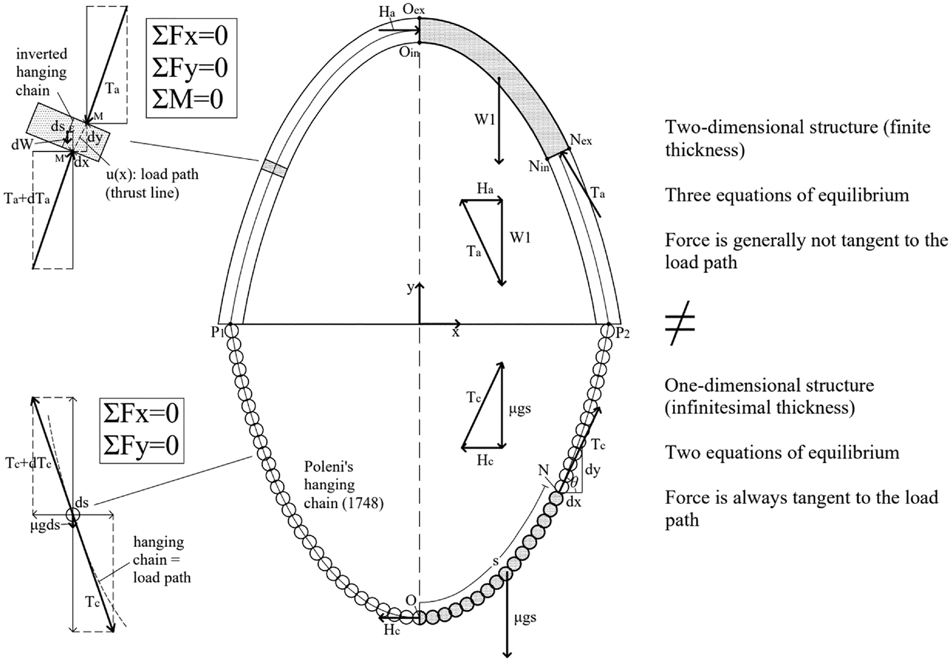
Regardless of the similarities, the hanging chain and its inverted arch are two incompatible structural systems.
Equation (1) derives after dividing the following expressions of force equilibrium in the y direction, by the one in x direction,

and acknowledging that
Johann Bernoulli’s expression, presented here in the form of equation (1), shows that the slope of the catenary, which coincides with the direction of the string force, is proportional to the arc length. This conclusion summarises the main properties of the catenary, which result by applying two-dimensional static equilibrium (or the “force polygon”) and the force tangency condition.
Bernoulli’s differential equation can be solved by differentiating further equation (1) with respect to x, and considering that

Different approaches are available to solve equation (3). One way is to let

Note that the integration constant is zero, since we have adopted the coordinate system shown in Figure 1, where the slope

where C is an integration constant. Note that at x = 0, the ordinate, y(x), takes the value
The properties of the catenary that derive from force equilibrium are reflected in the solutions of Leibniz and Huygens, although they did not provide a formula for the catenary [23–25]. Leibniz, in his 1691 solution, constructs geometrically the catenary based on an inversed logarithmic curve with base e, while estimating with impressive accuracy what later became known as the Euler’s number [24]. Leibniz describes the link between his inversed logarithmic curve, which can be perceived today as the exponential function,
Huygens had been experimenting at a younger age with force equilibrium by hanging weights from strings, demonstrating that the expression of the catenary cannot be the parabola [23]. His 1691 graphical representation shows that he was aware that the tensile force that develops along the hanging chain due to gravity needs to be tangent to the curve, while he accurately describes the shape of the catenary for three different “embrace” angles (i.e., the intersection angle formed by the lines of action of the tensile forces at the hanging points).
2.2. Variational formulation—stationary potential energy
Around 1692, in his scientific diary, the Meditationes, Jacob Bernoulli demonstrated that the catenary has the lowest centre of gravity among all curves of the same length [21]. In other words, the hanging chain assumes the form of the hyperbolic cosine function to minimise its potential energy. This is one of the earliest observations that mechanical systems choose the state of least (stationary) action, as was later formulated in Lagrangian and Hamiltonian Mechanics. It is noted that, at that time, the concept of calculus of variations was at a very early stage, as Newton’s minimal resistance problem had just been published in his Principia Mathematica in 1687, while the brachistochrone curve challenge was posed by Johann Bernoulli 4 years later, in 1696.
The same observation is used today to derive equation (5) by using calculus of variations to minimise the potential energy of the system. Our system is conservative, with zero kinetic and strain energy. In such case, the potential energy “due to position,”V, will express the whole “action” of the system, and at a state of equilibrium the following expression needs to be satisfied:

By taking any horizontal line as a reference (say, for instance, the x-axis of Figure 1), the potential energy can be expressed as,
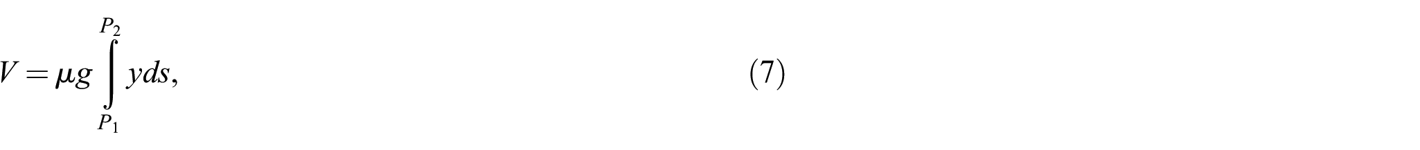
where P1(x1, y1) and P2(x2, y2) are the end points of the hanging chain. By substituting ds, as we did before for deriving equation (3), and disregarding the constant μg, the integral that we need to minimise becomes [18],
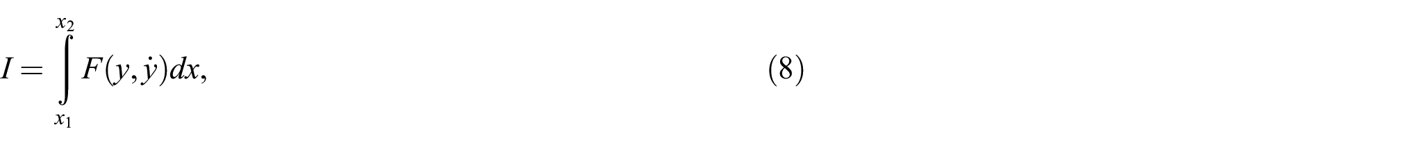
where F is the functional

where c is a constant. After substituting F, equation (9) becomes,

which reduces to [18],

After integrating equation (11), the catenary equation emerges:

3. Hooke’s analogy between hanging chains and arches
The challenge of sizing the thickness of stone arches continued to be at the forefront of structural engineering through the centuries [27]. Hooke [11] was apparently the first to publish a rational rule for sizing masonry arches by describing the analogy in the load path between the hanging chain, which forms a catenary in tension under its own weight; and an arch that stands under compression. This analogy conceived by Hooke is expressed in the literature “As hangs the flexible line, so but inverted will stand the rigid arch” [28,29].
A few years after the 1691 solutions of the catenary discussed previously, Gregory [30] stated that a masonry arch is stable if it is thick enough to accommodate a catenary, which is considered the first statement of the lower bound theorem for the stability of masonry archers. Indeed, if the arch can accommodate a physically realisable load path of the resultant compressive forces, and assuming sufficient frictional resistance and compressive strength, it will not form a collapse mechanism. It is pointed out, however, that as was shown by the authors [31–34], the catenary challenges the equilibrium of any masonry arch with finite thickness and cannot be a physically realisable load path (thrust line). This is further discussed in Sections 3.1 and 3.2.
Fifty years later, Poleni [22] used the idea of the inverted hanging chain to assess the safety of the cracked dome of Saint Peter’s Church in Rome. The reader is referred to Poleni’s famous XII and XIV illustrations, which can be found in Heyman’s [28] Structural Analysis book (among other sources available on the Web). In his XII illustration, Poleni presents the way he conceived Hooke’s analogy, by drawing the inverted hanging chain as a line of infinitesimal thickness, and not as an arch with finite thickness. As will be discussed in the following sections, 3.1 and 3.2, although this is a fictitious construction, it is an accurate representation of Hooke’s analogy, as both structures in Poleni’s illustration are one-dimensional, and the analogy holds.
In order to apply Hooke’s idea to study the stability of curved structures with finite (real) thickness, and in particular the Saint Peter’s Church dome shown in his XIV illustration, Poleni did not just draw catenary curves, as Gregory suggested. He realised that the analogy between the hanging chain and the load path of the resultant thrust force of the dome may be improved by hanging proportional weights to the weights of corresponding sections of a slice of the dome. In that way, the lines of actions (directions) of the forces are proportional to the resultant compressive forces acting on the corresponding sections of the dome. Even though the idea that the shape of a weightless string with specific hanging weights indicates the direction of the forces acting on the string (satisfying in that way equilibrium) was developed much earlier by Stevin [35], Poleni’s straightforward application marks the beginning of the graphical methods for the stability analysis of masonry arches that prevailed until the establishment of linear elastic theory during the first half of the 20th century [15,36]. It will be discussed in Sections 3.3 and 3.4 though, that this construction, although an improved “hanging chain” tool to study the stability of arches, it remains consistent with the equilibrium of one-dimensional strings and not with two-dimensional structures.
3.1. Inverted catenary versus load path
For the two-dimensional equilibrium analysis of a masonry structure composed by rigid blocks, the “thrust line” (also reported as the “druckkurve” by Milankovitch [37,38]) is defined as the geometrical locus of the points of application of the resultant thrust force that develops at the joints.
Figure 1, bottom, shows Poleni’s hanging chain of the XII illustration. By inverting the hanging chain, we obtain the mid-thickness line of the catenary arch. It is widely accepted, even today, that the inverted catenary represents the load path of the compressive forces of the arch. Figure 1 provides a summary of the key ideas discussed previously by the authors [31–34] to highlight why the hanging chain and the arch are two incompatible structural systems.
As shown in Figure 1, the hanging chain considered is a one-dimensional structure of infinitesimal thickness and zero bending stiffness. As a result, a geometric formulation requires only translational force equilibrium to be satisfied, while rotational equilibrium is satisfied by default. In other words, ΣFx = ΣFy = 0 is a necessary and sufficient condition to keep the rings of the chain (or segments of the string) in equilibrium. As shown in Figure 1, bottom-left, ΣM = 0 is identically satisfied, as all forces acting on the ring of the chain, which is assumed to have infinitesimal dimensions, intersect at the ring, while the resultant tensile forces of the hanging chain are tangent to the chain. Direct consequence of all the above is that the hanging chain assumes the shape of the load path or it is the actual load path.
In contrast with the above, the arch is considered a two-dimensional structure with finite (real) thickness. As a result, the geometric formulation requires both force and moment equilibrium to be satisfied. In other words, in this case, ΣFx = ΣFy = ΣM = 0 is the necessary and sufficient condition to keep the arch or arch stones/segments in equilibrium. As shown in Figure 1, top-left, even if a slice (or stone) has infinitesimal thickness, say ds at the mid-thickness, its size in the other (perpendicular) direction is finite, as it represents the arch thickness. Note that in the case of chain-ring equilibrium, all dimensions are assumed infinitesimal, and all forces intersect by default. As a result, the distance, ε, between the point of application of the resultant thrust force that develops at point M′ and the centre of gravity of the slice is finite (see Figure 1), while the location of the centre of gravity depends on the stereotomy exercised and does not necessarily belong to the mid-thickness line. This was observed first by Milankovitch [37,38] (see also Makris and Alexakis [32]), who by taking equilibrium about M′ showed that,
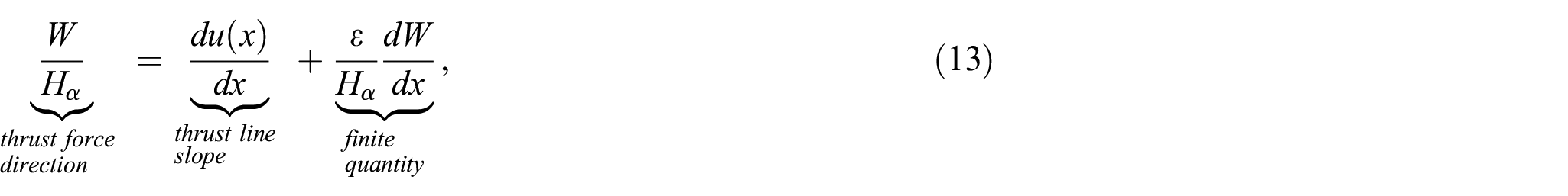
where W and dW are the weight of half the arch and the slice, respectively, and u(x) is the expression of a physically realisable thrust-line curve, unique for each stereotomy assumed [31–34]. As a result, in the general case that the distance ε is finite, which is consistent with realisable stereotomies, the thrust force is not tangent to the thrust line, while the thrust line will assume the form that satisfies both translational and rotational equilibrium, and not that of a one-dimensional structure.
Milankovitch [37,38] (see also Makris and Alexakis [32]) explored the theoretical case when ε is always infinitesimal. This holds only when all cuts of the slices in the analysis are assumed (1) parallel to each other, and (2) the resultant external loads acting in all slices are parallel to the cuts. For the special case of a uniform gravitational field without the exertion of other external forces, if all cuts and gravity loads are vertical, then ε vanishes. As a result, one may obtain a new thrust line that Milankovitch called the Stützlinie. Although for this line the force tangency condition holds as a consequence of equation (13), it was shown in [32,34] that this line is not the catenary curve.
In structural analysis, assuming vertical cuts is a convenient approach, as it is consistent with the adoption of a Cartesian coordinate system. This idea was materialised in the form of the “slicing technique” adopted broadly by Graphic Statics and relevant modern form-finding algorithms that followed. This, however, is incompatible with stereotomies found in practice, where the equilibrium of real stones/blocks needs to be satisfied.
3.2. Reductio ad absurdum
Let’s now examine more closely the widely accepted idea that the inverted catenary represents the load path of the compressive forces of the catenary arch, by applying similar equilibrium to an arch segment, as we did in Figure 1, bottom, with the hanging chain to derive equation (5).
In Figure 2, consider for simplicity the case where the highest point of the mid-thickness line of the arch, Om, has coordinates (0, Rm), and the hanging points P1 and P2 have coordinates (–Rm,0) and (Rm,0), respectively. Due to symmetry about point Om, in Figure 2, we present only the right half of the arch. If, t is the thickness of the arch at the crown and of the base (springings), the mid-thickness, extrados and intrados lines of the catenary arch are expressed as:


where
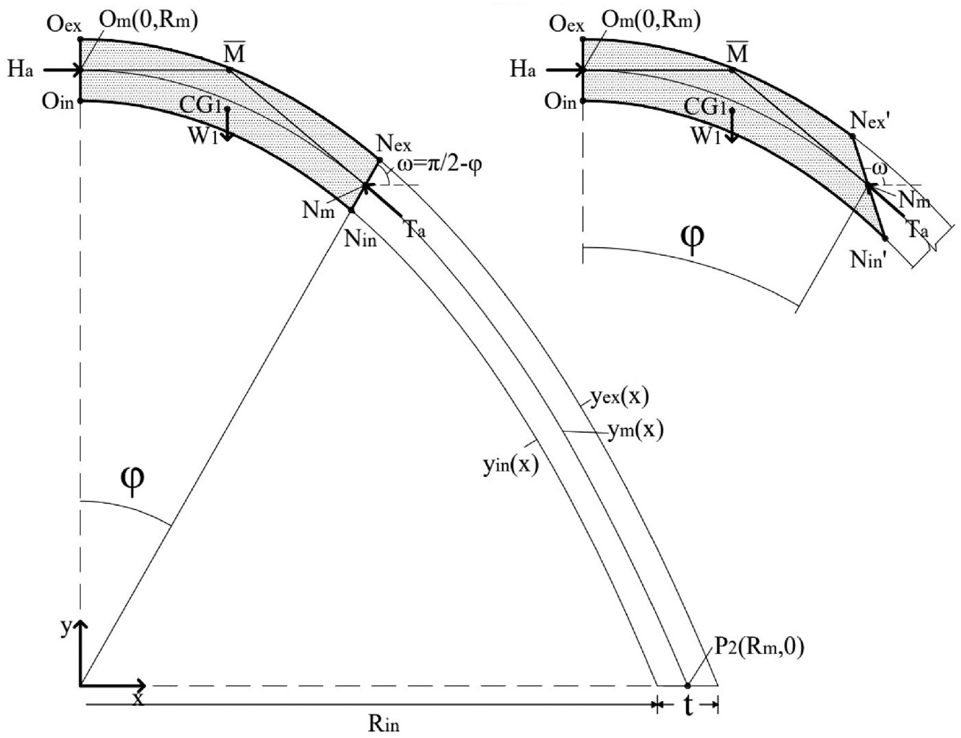
Left: Assuming that the catenary (here, the mid-thickness line) is a physically realisable load path, rotational equilibrium is violated, as the lines of action of the gravity load and thrust forces do not necessarily intersect (i.e., point
By assuming that the inverted catenary, ym, is an acceptable thrust line and that the force tangency condition holds, the resultant compressive force, Ha, at the crown will be horizontal and applied at the mid-thickness.
Let’s consider equilibrium of the shaded segment of the arch in Figure 2, as we did with the hanging chain in the previous section, from point Om to point Nm, where Nm is a point of the mid-thickness line at an angle φ measured from the y-axis. Let’s also assume a radial cut from point Nin to Nex at the same angle φ, or at an angle ω of the cut measured from the horizontal equal to π/2 – φ.
The lines of action of the thrust forces at points Om and Nm meet at the intersection point

By observing closely Figure 2, there is no reason that restricts the intersection point
A numerical example is provided below:
Let’s assume that Rm = 1, t/Rm = 0.1, and φ = 30°. In such case, am = aex = ain = 0.61876, xNm = 0.46948, xNex = 0.49296, xNin = 0.44601, and from equation (16), xM = 0.24539. The abscissa of CG1 can be calculated from the following expression,
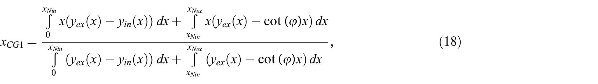
which gives xCG1 = 0.24226 ≠xM = 0.24539, and hence, moment equilibrium is not satisfied as expected.
Now, one may suggest that there is a special cut passing from Nm so that xM = xCG1 to satisfy moment equilibrium. The horizontal thrust at the crown can be calculated by taking moment equilibrium of half the arch about P2. Consequently,

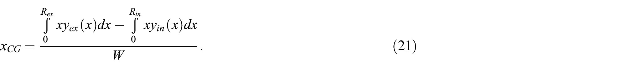
where W is the gravity load and xCG the abscissa of the centre of gravity of half the arch is given by,
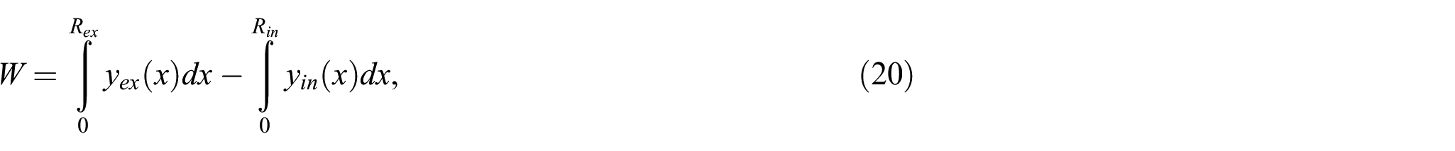
and
For simplicity, in the above equations, it is assumed that the weight per area is unity, and hence, Ha = 0.05857.
Let’s make a new cut passing through Nm at an angle ω from the horizontal, so that xM = xCG1. The abscissa of the new points Nin′ and Nex′ can be found by solving the equations,

and

while the centre of gravity of the new shaded segment of Figure 2, right, again from equation (18).
Based on the above expressions and by keeping the same numerical values of the example, xM = xCG1 when ω = 107.97634°. In such a case, however, force equilibrium (or “closing” the force polygon) requires the direction of the resultant thrust force to be equal to arctan
Hence, by reductio ad absurdum, the assumption that the inverted hanging chain is a physically realisable load path of forces that satisfy both translational and rotational equilibrium in an arch with finite thickness, even in the case of the catenary arch, cannot hold.
The above exercise can be repeated for various arch geometries, segments, and stereotomies leading to the same conclusion. When the thickness of the catenary arch approaches to zero however, then the influence of the stereotomy becomes marginal and the deviation between the direction of the thrust force and the mid-thickness line converges to zero. As Poleni correctly illustrated, Hooke’s analogy holds when comparing systems that are both one-dimensional.
3.3. Funicular line versus load path
In his XIV illustration, Poleni [22] hanged from a chain proportional weights to the weights of corresponding sections of a slice of Saint Peter’s Church dome, and subsequently, he inverted this new line to apply Gregory’s [30] lower bound stability criteria. By drawing this inverted hanging chain model, Poleni did not find exactly the load path of the resultant thrust force, but a neighbouring line, the “funicular line.” Note that the funicular line is generated by the lines of actions of the resultant thrust forces (funicular polygon) and not by their points of applications, which generate the thrust line (the load path).
In an effort to better understand the subtle differences between the thrust line and Poleni’s funicular line, Figure 3 shows two similar masonry structures in equilibrium. The first structure is composed by five square blocks of the same area and weight (W1 = W2 = W3 = W4 = W5). In the second structure, the shape and location of the three intermediate blocks has been altered in a way that the two structures still have blocks of the same area and weight, and the location of centre of gravity for each block remains unchanged.
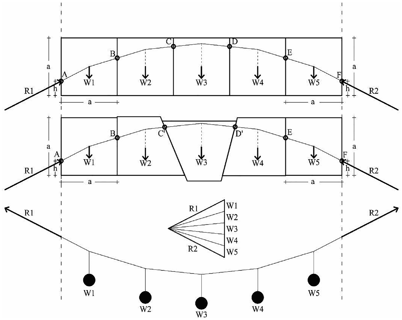
Same funicular line may correspond to an infinite number of different two-dimensional structures, with different stereotomies, and as a result, different thrust lines (load paths).
By making the assumption that the reaction forces R1 and R2 that hold the structures in equilibrium are applied at the same vertical distance h from the bottom of the extreme blocks, one may construct a suitable funicular polygon that satisfies equilibrium, as shown in Figure 3. Given that the size and point of application of all forces (reaction forces and block weights) is identical in the two structures, the calculated funicular polygons will be identical for both structures.
Figure 3, bottom, shows a representation of a hanging chain, which was constructed based on the direction of the resultant forces indicated by the funicular polygon. The string represents the funicular line, which is reversely drawn within the structures. The intersection points of the funicular line with the joints represent the point of application of the resultant thrust forces calculated by the funicular polygon, so that the three equations of equilibrium are satisfied for each block. Clearly, intersection points C′ and D′ of the second structure are different compared to the points C and D of the first structure. Consequently, although the funicular line was identical for both structures, the thrust line (load path), which is the geometrical locus of the points of application of the resultant thrust force that develops at the joints, can be different depending on the stereotomy exercised. This is because a physically realisable thrust line derives from equilibrium of two-dimensional blocks when the geometry of the blocks (and hence the stereotomy exercised) matters, while the funicular line derives from the equilibrium of the one-dimensional string, inherently omitting the stereotomy exercised.
Based on the example presented in Figure 3, one may rush to conclude that the points of applications of the thrust force belong to the funicular line. However, this is not always the case, as shown in Figure 4. Figure 4 shows the free body diagram of two blocks stacked on top of each other at different orientations, by keeping the direction and magnitude of the applied forces unchanged. Figure 4(a) shows the funicular polygon, which is the same for all cases (b)–(e). The structure is subjected to an external load, F, and by accounting for the weights of the blocks W1 and W2, the force polygon calculates the direction and magnitude of the reaction force at the base, R, and of the resultant thrust force that is exerted on the interface between the blocks.
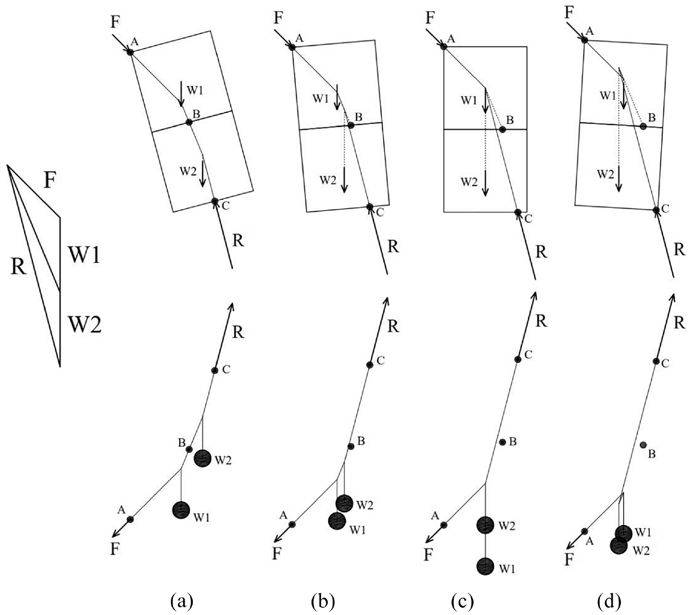
(a) Same force polygon for different orientations of the same structure; (b) the points of application of forces, which form the load path, belong to the funicular line only in the special case when all force-intersection points are within the corresponding blocks; (c, d) as the structure rotates, the point of application of thrust force B is shifting away from the funicular line; (e) the funicular line hanging chain concept fails to describe equilibrium.
Only when the line of action of the weight of a block intersects with the funicular line inside the block, then the point of application of the resultant thrust force belongs to the funicular line, as shown in Figure 4(b), bottom. However, if the intersection happens outside the block, as in the case of W2 in Figure 4(c), the point of application of the force in the interface, B, starts to deviate from the funicular line, as moment equilibrium must be satisfied for each individual block. Figure 4(d) shows the limit case when the lines of actions of the weights coincide, whereas Figure 4(e) shows that if we rotate further the structure, the concept of “inverting the shape of a string with individual weights” (Figure 4(e), bottom) fails to describe equilibrium.
3.4. Vertical slicing limitations
The previous section shows that the funicular line, which is the line generated by the lines of actions of the resultant forces, is neighbouring to the load-path line, and can be graphically used as an intermediate step for the calculation of the thrust line, with the condition that the true stereotomy is considered.
The funicular lines presented in Figures 3 and 4 consider the true locations of the centres of gravity of the blocks in equilibrium. Alternatively, one may graphically construct funicular lines by omitting the stereotomy exercised, and considering the weights derived from successive vertical slices (or cuts). This famous technique, reported in literature as the “slicing technique,” has been widely used in Graphic Statics and relevant modern form-finding algorithms due to its simplicity and direct relevance with vertical projections and consistency with a Cartesian coordinate system.
Indeed, by taking vertical slices in a curved structure subjected to gravity loads only, one may construct a fictitious load path, which however may be very close to the one derived by considering the true stereotomy, with certain limitations though, as explained below. For this reason, the slicing technique remains a useful tool for quick form-finding and visualisation.
For instance, Figure 5 shows the right half of a semi-circular arch with thickness—mid-radius ratio, t/R = 0.2. Two physically realisable thrust lines have been constructed from points Oex to Pex, by using an in-house software that applies translational and rotational equilibrium to successive blocks to find the points of application of the resultant forces. One line is constructed by considering successive radial cuts that is consistent with the stereotomy that semi-circular arches typically exert in practice, and the other by considering vertical cuts. The curves are identical with the closed-form expressions of Milankovitch [37,38] and Makris and Alexakis [32]. The enlarged box in Figure 5, right, shows that the solutions are very close, and the minimum thickness at the limit equilibrium state is t/R = 0.1075 and 0.1095, respectively [32,37,38]. This is a deviation of about 2%, which is considered acceptable in structural engineering practice. The deviation remains small for most shallow or slender elliptical arches [34].
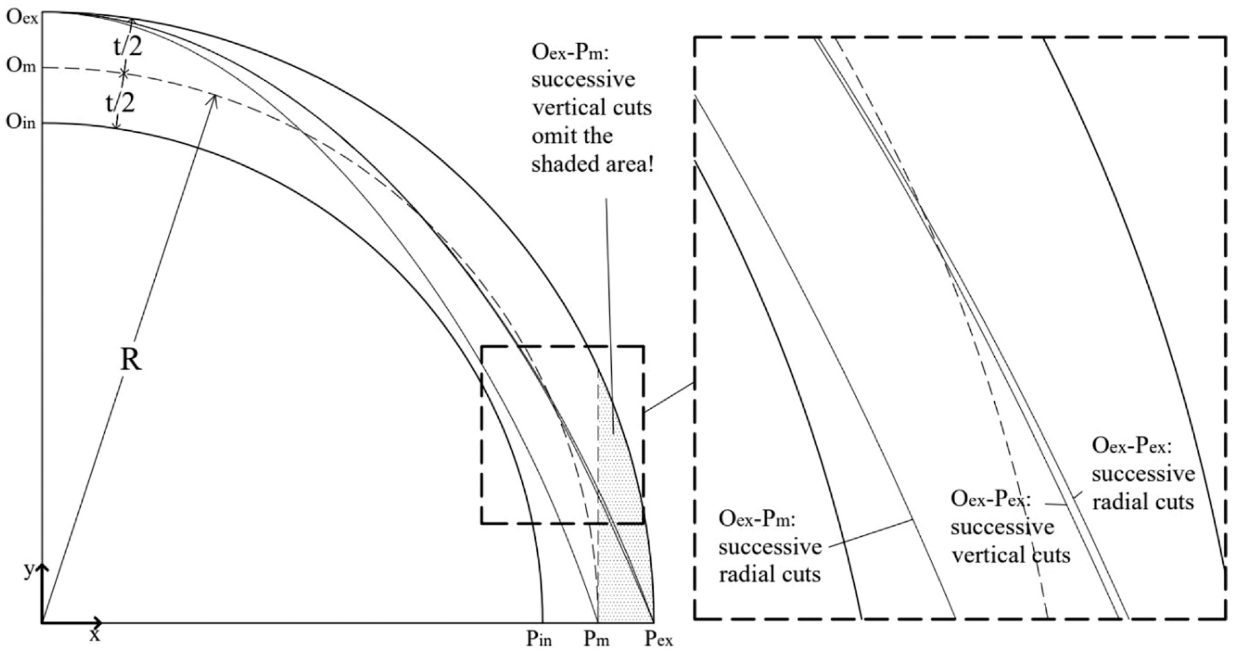
In the simple case of solely gravity loads, when the point of application of the reaction force at the springing is not assumed to be at the extrados, Pex, equilibrium analysis based on “vertical slicing” omits areas of the arch that in reality contribute to the equilibrium. In this example, t/R = 0.2.
In Figure 5, our analysis proceeds with deriving the thrust line from Oex to Pm by assuming successive radial cuts and that the point of application of the resultant reaction force at the springing is not necessarily at the extrados (say here it is at the mid-thickness). Note that the slicing technique from Oex to Pm will omit the shaded area, which is the weight beyond point Pm that in reality participates in equilibrium. In other words, under vertical gravity loads, the slicing technique and relevant algorithms may consider only the mass that is enclosed within the projection of the derived curve to the horizontal.
This restriction is not critical if the expected hinge at the limit equilibrium state is at the extrados of the structure, as all mass is considered by taking vertical cuts. This limit state equilibrium, for instance, is consistent with a five-hinge mechanism that causes the lower segments of the structure to bow outwards. Note, though, that this is not the only mechanism assumed in symmetric arches under gravity loads. For instance, slender pointed [39] or parabolic [4] arches may experience the reversed collapse mechanism, so that the lower hinge is located at the intrados, not at the extrados, and hence, the slicing technique would omit significant mass contribution from the analysis.
There are further limitations if someone wants to consider loading conditions beyond solely gravity loads, such as lateral loads (e.g., inertial or wind) or concentrated vertical loads, as more complex mechanisms may be imminent, and considering the true stereotomy is critical. For instance, Figure 6 shows the same semi-circular arch t/R = 0.2 subjected to both gravity and lateral uniform inertial loading with seismic coefficient ε [34]. Variational calculus (discussed in the following section) has been used to calculate the four-hinge collapse mechanism shown in Figure 6 by assuming radial stereotomy. The arch is at the limit equilibrium state and the thrust line is passing through hinges A, B, C, and D at angles, φ, equal to 0°, 45.4325°, 105.84°, and 166.247°. By tilting the axis at an angle of ω =arctan(ε), hinge C belongs to the new vertical axis, y′, and all external forces are now vertical in a new gravitational field enhanced by the term
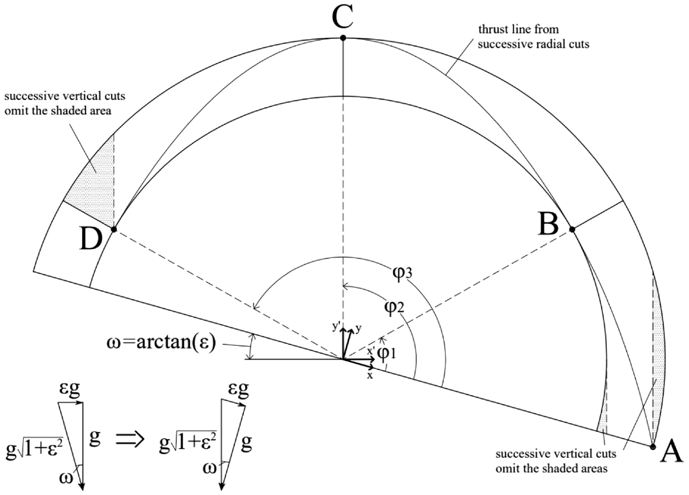
Semi-circular arch under lateral and gravity loads, showing areas that cannot be considered in vertical slicing technique. In this example, t/R = 0.2, ε = 0.28372, φ1 = 45.4325°, φ2 = 105.84°, φ3 = 166.247°, and the arch is at a limit equilibrium state when radial stereotomy is assumed [34].
By using the force polygon and point C as a starting point, similar to points O or Oex in the previous sections, one may graphically derive the thrust line shown in both directions, both from C to D, and from C to A, with the condition that the true stereotomy is considered. Here, the thrust line shown has been constructed as in Figure 5 by considering successive equilibrium of blocks and radial stereotomy, which is in absolute agreement with the variational formulation results. Note that considering a graphical tool based on vertical cuts following the slicing technique is impractical, as the shaded areas shown, which grow as the lateral loading increases, cannot be considered in the analysis. Figure 6 also shows that, even in the case when the hinges at the base of a structure are considered at the outer surface, the slicing technique cannot deal with segments not included within the vertical cuts.
4. Studying equilibrium curved structures with variational calculus
The previous section shows that when analysing the general case of curved structures with real stereotomies (i.e., beyond exclusively vertical cuts), considering loading conditions beyond gravity alone, and exploring mechanisms that are not restricted to the formation of hinges at the outer boundaries, it is critical to be consistent with the geometric formalism and the stereotomy exercised, and ensure that equilibrium in each block or segment is satisfied.
Deriving graphically load paths for quick visualisation and form-finding that are consistent with force equilibrium is not always a straightforward process, as this would require in many cases a full rigid-block equilibrium analysis, such as the Discrete Element Method [40,41]. This approach considers the equilibrium of each individual block, and requires a detailed description of the geometry at a micro-level. Even if automating the discretisation of models is enhanced in the future (e.g., importing detailed information from three-dimensional scanning), describing the internal structure will still require assumptions and simplifications. So, studying the macroscopic equilibrium of curved structures by finding load paths or collapse mechanisms, without the need to describe in detail the internal/micro geometry, will remain a practical tool for optimal design (form-finding) and stability assessment.
Following the transition in Science from Newtonian to a Lagrangian description, one may obtain rigorous solutions without the need to consider individual block equilibrium or deriving thrust-line curves, and study the limit equilibrium state of curved structures by searching for the state of stationary action.
Similar to Section 2, when we derived the catenary expression in equation (12) with variational formulation, incompressible curved structures at their limit equilibrium state are conservative systems without kinetic or strain energy, and their “action” is represented entirely by their potential energy “due to position.” Hence, the preferred limit equilibrium state of the uncracked (still) structure is dictated by the principle of stationary potential energy, δV = 0, as in equation (6).
When the family of candidate imminent mechanisms may be described by i number of geometric parameters, qi, then the potential energy will have the form of V(qi), and equation (6) will require the satisfaction of the following system of equations (see also Shames and Dym [42]):

In other words, the task has been simplified in expressing the potential energy, V, in terms of the unknown geometric parameters, qi, and satisfy equation (24). Note that the terms qi may represent any unknown geometric parameters that describe the imminent mechanism of the uncracked structure, such as the location of the imminent ruptures or the thickness of the arch.
Examples of expressing V in terms of qi and rigorous solutions for the limit equilibrium state of various structures can be found in previous studies of the authors, and in particular, for describing the limit state of semi-circular [32] and elliptical arches [34] under gravity loads, and circular [33] and buttressed arches [43] under gravity and lateral loads, as shown in Figure 7. More recently, the method was applied for optimising the form of extra-terrestrial, parabolic curved structures [4]. In all cases, the expression V(qi) can be derived by taking moment equilibrium around the hinges of the different segments of the imminent mechanism, which are numbered in Figure 7. The solutions are in absolute agreement with geometric solutions derived by implementing Newtonian equilibrium that considers the stereotomy exercised [32,34,37,38].
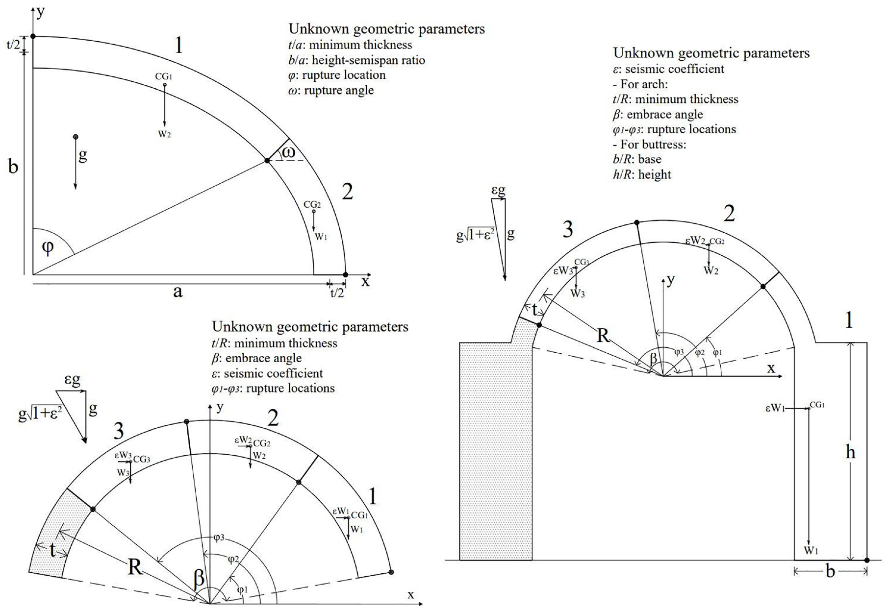
Application of the principle of stationary potential energy expressed by equation (24) to find the limit equilibrium state (i.e., unknown geometric parameters shown) of different structures. Top-left: Elliptical arches under gravity loads. Bottom-left: Circular arches under inertial and gravity loads. Right: Single-nave barrel vaults under inertial and gravity loads.
5. Conclusion
Refining the design and assessment tools for curved structures will enhance the use of low-carbon natural materials in construction and maintenance of heritage buildings and infrastructure.
Inverted hanging chains and funicular lines have been associated with the load path of masonry arches for centuries. Adopting the principles of Graphic Statics in computer programmes appears today particularly useful for architectural design and form-finding applications.
The paper revisits the equilibrium of the hanging chain, by following the transition from Newtonian to Lagrangian Mechanics that allowed the development of modern physics and mathematics.
By applying Newtonian equilibrium, it is shown that the hanging chain and its inverted arch are two incompatible structural systems, as the first requires only translational equilibrium to be satisfied, while the second both translational and rotational. Using elements of lower dimensions (e.g., a string) to study the equilibrium of structures of higher dimensions results in subtle inconsistencies that this work further explores.
It is shown that the funicular line inherits the properties of the hanging chain, which is a one-dimensional structure and should be used with caution to study the stability of curved structures. The funicular line, which is the line generated by the lines of actions of the resultant forces, is neighbouring to the load-path line, and can be graphically used as an intermediate step for the calculation of the thrust line. However, this requires considering the stereotomy exercised and that equilibrium in all segments of the arch is satisfied.
Vertical projections and slicing techniques that omit the stereotomy exercised are widely used in Graphic Statics due to their directness, simplicity in visualisation, and consistency with Cartesian coordinate systems. The deviation from a solution that satisfies higher-dimension equilibrium is marginal in the special case when we study the equilibrium of relatively horizontal segments, with relatively vertical joints, under solely gravity loads. However, moving towards the implementation of building codes in practice that impose a variety of loading conditions beyond gravity loads (e.g., seismic, wind), it is essential to be able to study the stability of structures that may have a wider range of forms and stereotomies, and explore various collapse mechanisms.
Following the example of the catenary form-finding problem, one may implement the principle of stationary action to study the limit equilibrium state of curved structures, without the need to consider equilibrium of each individual block or describing geometrically the load path of thrust forces. The method offers rigorous solutions and is in absolute agreement with Newtonian equilibrium.