
Abstract
A direct method is proposed to study wave dispersion in stiff unidirectional fiber-reinforced elastic random composites. The present model is featured by a modified form of classical elastodynamic equations supplied with a simple differential relation between the displacement field of the composite and the displacement field of the mass center of representative cell. Explicit formulas are derived for the attenuation coefficient and effective phase velocity of in-plane P-waves, SV-waves, and anti-plane SH-waves, respectively. The efficiency and accuracy of the model are demonstrated by comparing predicted results (on the frequency for the maximum attenuation and effective phase velocity at frequencies below the bandgap) with a large group of known data reported in past decades. The proposed model offers a novel general method for dynamics of stiff unidirectional fiber-reinforced elastic random composites.
1. Introduction
Unidirectional fiber-reinforced composites find important application in numerous industrial areas [1–4], and the study of their mechanical behavior is a topic of long history [5–9]. In the past decades, dynamic behavior, particularly scattering-caused wave attenuation, of unidirectional fiber-reinforced elastic composites has been the topic of numerous researches [10–24]. Existing works studied wave scattering of unidirectional fiber-reinforced composites and developed numerical models for wave dispersion based on various effective medium theories. Extensive numerical calculation is usually requested for wave dispersion analysis, and different numerical models often give quite different results for attenuation and phase velocity, typically with 20%–30% or even larger relative errors between different models. To mention a few, for example, Wang and Gan [19] studied phase velocity and attenuation of anti-plane SH-waves of fiber-reinforced composites with a self-consistent scheme; Sato et al. [12] developed a plane-strain boundary-element analysis of P/SV-waves for stiff fiber-reinforced concretes; Kim [21] conducted a comparative study on anti-plane SH-waves in fiber-reinforced composites; and more recently, Sumiya et al. [16] developed a computational analysis of P/SV-waves in fiber-reinforced composites, Zhang et al. [24] conducted a numerical simulation on effective phase velocity and attenuation of SH-waves in fiber composites, and Yu et al. [13] studied P-waves in aluminum rod-reinforced polymers with a plane-strain two-dimensional numerical model.
In spite of extensive research, however, most existing models usually request rather complicated mathematical formulation and extensive numerical calculations, and different models often give quite different, or even qualitatively different, predictions particularly on wave attenuation, see, for example, comparative studies [13,15,18,19,21]. For example, it remains a relevant question how to predict the frequency for the maximum wave attenuation. Therefore, it is of theoretical and practical interest to develop new analytical models for wave dispersion in unidirectional fiber-reinforced elastic random composites.
The present work aims to develop a new general model to analyze elastic wave propagation in stiff unidirectional fiber-reinforced random composites. Unlike existing models, the present model is based on the concept that the derivation of the displacement field of embedded stiff fibers from the displacement field of the composite dominates wave dispersion of stiff unidirectional fiber-reinforced elastic composites. As shown in section 2, the novelty of the present model is featured by the idea to modify the classical elastodynamic equations by substituting the inertia term by the acceleration field of the mass center of the representative unit cell, which is supplied with a simple differential relation between the mass center’s displacement field and the composite’s displacement field. Explicit dispersion relations are derived in section 3 for P-waves, SV-waves, and SH-waves. The efficiency and accuracy of the proposed model are demonstrated in section 4 by comparing its predicted results to known data reported in past decades. Finally, the main conclusions are summarized in section 5.
2. Basic equations of the present model
Since transversely isotropic (such as carbon) fibers are widely used in industries, let us consider a transversely isotropic elastic composite comprised of an isotropic elastic matrix (of the Young’s and shear moduli Em and Gm) reinforced by transversely isotropic cylindrical fibers (defined by five independent elastic constants: E1 f , E2 f , G12 f , G23 f , ν12 f ) aligned along the x1-axis and randomly distributed with a constant volume fraction δ, as shown in Figure 1. Here, it is assumed that the identical fibers are of circular cross section of radius a, and the elastic moduli of fibers are much (say, at least 4–5 times) higher than that of the compliant matrix so that the elastic solutions given in Appendixes 1 and 2 for a rigid circular fiber can be used, and the characterized wavelengths are much larger than the diameter of fibers and the average distance between the centers of adjacent fibers.
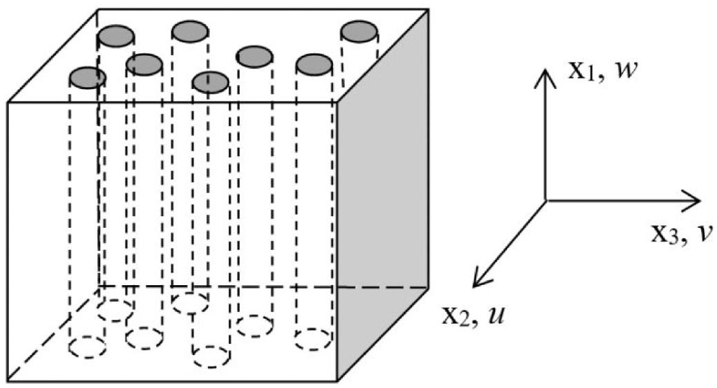
Unidirectional fiber-reinforced elastic random composites.
Based on a widely accepted idea that the derivation of the displacement field of embedded stiff fibers from the displacement field of the composite is largely responsible for novel dynamic behavior of stiff unidirectional fiber-reinforced elastic metacomposites, let us consider two x1-independent (plane or anti-plane) displacement fields: the displacement field

where δ is the volume fraction of the embedded fibers, and ρm and ρf are the mass densities of the matrix phase and the embedded fibers, respectively. For any deformable material element such as a representative unit cell, the resultant external force acting on the element equates to the mass of the element multiplied by the acceleration of its mass center. Thus, in the absence of body forces, the following modified form of classical (plane or anti-plane) elastodynamic equations is proposed where the inertia term on LHS is substituted by the acceleration field of the mass center of the representative unit cell:
where σij (i, j = 1, 2, 3) are the (symmetric) stress components which can be given in terms of the displacement field

For stiff unidirectional fiber-reinforced composites characterized by stiff (such as steel/glass/carbon) fibers and soft matrix phase (such as polymer or rubber), the deviation (
Based on the spring model for the x1-independent displacement field of a single rigid fiber surrounded by an infinite effective medium (see Appendix 2), we have a simple differential relationship between

where the spring constant β (per unit volume of the composite) is given in Appendix 2 for the decoupled plane strain–stress case (between (umass, vmass) and (u, v)) and anti-plane case (between wmass and w), respectively, also see equations (9) and (23). Thus, with the present direct method, the x1-independent (plane or anti-plane) dynamics of stiff unidirectional fiber-reinforced composites is governed by the modified form of classical equation (2) coupled with the differential relation equation (4) between the mass-center displacement
3. Dispersion relations for plane waves
As compared to existing methods [10–24], the present model based on governing equations (2) and (4) enjoys conceptual and mathematical simplicity and the generality although it is restricted to stiff fibers whose elastic moduli are much higher than those of the compliant matrix. In this section, explicit dispersion relations will be derived from equations (2) and (4), for various plane waves in the stiff unidirectional fiber-reinforced elastic random composites.
3.1. Longitudinal P-waves
First, let us consider the plane P-waves under the conditions of plane strain with u(x2, x3, t) and v(x2, x3, t) and w ≡ 0 (see Figure 1). In terms of the two effective elastic coefficients (c22, c23), the stress–strain relations in plane-strain conditions are given by (see Appendix 1),

where,

For plane P-waves propagating in x2-direction, we have u(x2, t) with v = 0, thus

Thus, for harmonic P-waves u(x2, t) =u0e-i(kx2-ωt), where u0 is a constant, ω is circular frequency, and k is the wave number, then,
Within the following range of frequencies (called the “bandgap” for P-waves and SV-waves under plane-strain, where κ = 3-4ν23, see Appendix 2),

We have,
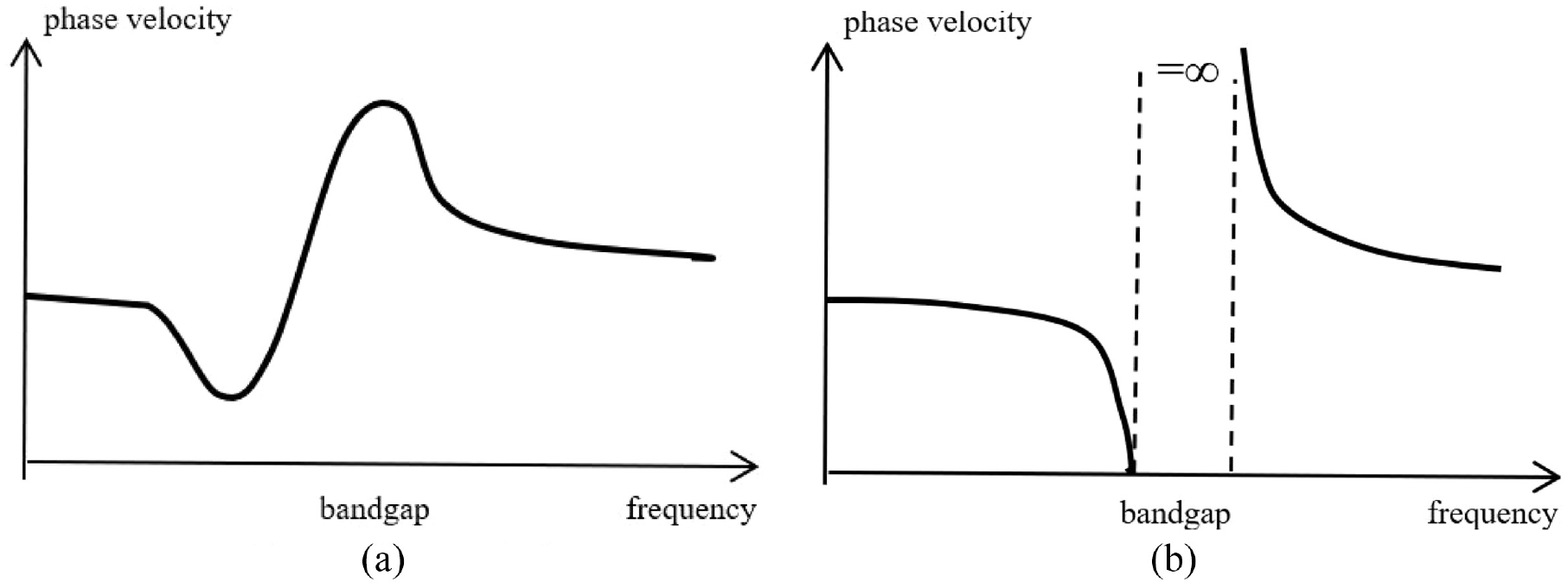
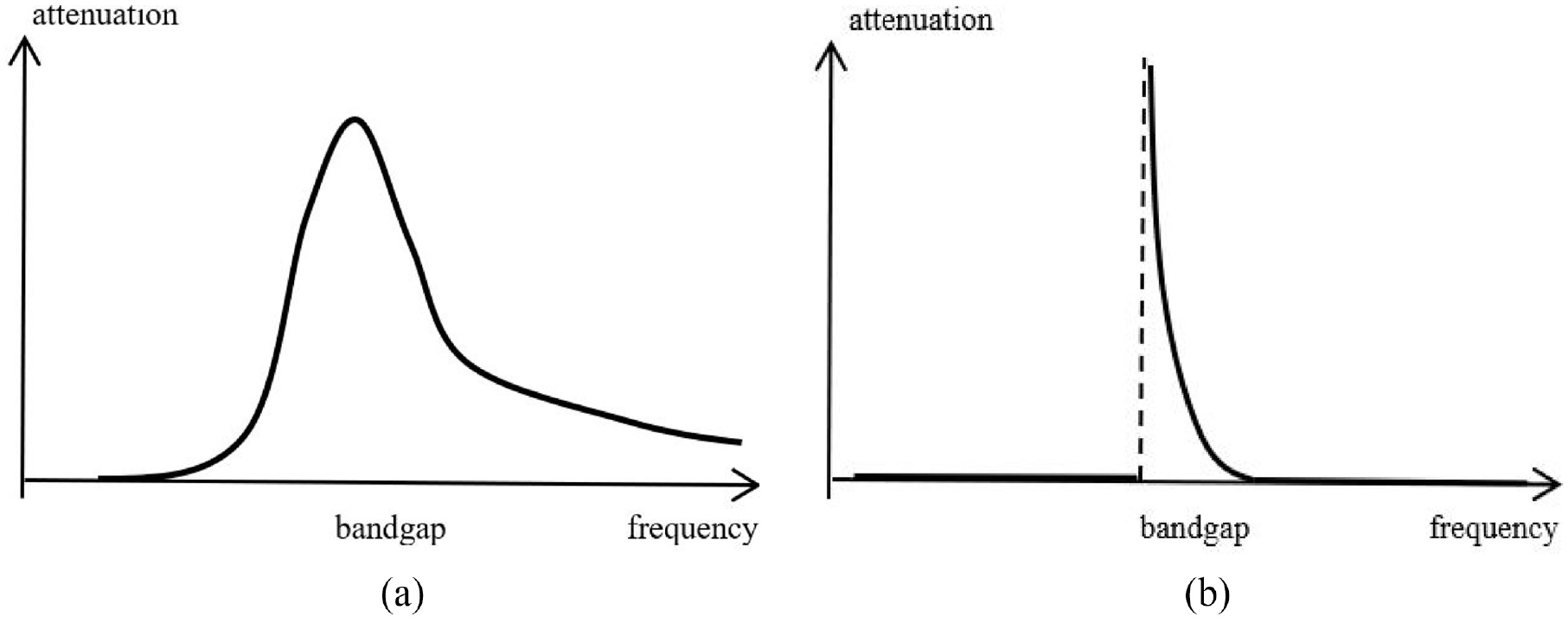
For a visual illustration of general wave behavior predicted by the present model without any restriction to specific material and geometrical parameters, phase velocity and attenuation predicted by the present model are shown graphically in Figures 2(b) and 3(b) without specific parameters, with a comparison to actual wave behavior of unidirectional fiber-reinforced elastic composites shown in Figures 2(a) and 3(a). Thus, it is seen from Figures 2(b) and 3(b) that the phase velocity given by the present model is infinite within the bandgap equation (9) while the attenuation is infinite at the lower cut-off frequency ω0 and decreases to zero at the upper cut-off frequency of the bandgap, while actual phase velocity and attenuation of unidirectional fiber-reinforced composites observed in experiments or predicted by more complicated numerical models (see, e.g., several studies [10–13,17–21]) are illustrated in Figures 2(a) and 3(a), respectively. Clearly, the actual attenuation at the local resonance frequency ω = ω0 cannot be infinite, and the actual phase velocity within the bandgap cannot be infinite. It is not surprising that, just similar to all linear undamped theories on resonance, the present (linear and undamped) model cannot give quantitative details of resonant behavior at and around the local resonance frequency ω = ω0. In spite of this, however, the results given by the present model (shown in Figures 2(b) and 3(b)) are qualitatively consistent with actual wave behavior (shown in Figures 2(a) and 3(a)), because both show that the phase velocity rises up to the maximum around the bandgap while the attenuation rises up abruptly to the highest peak around the local resonance frequency ω = ω0.
On the other hand, outside the bandgap equation (9), the present model gives that the attenuation α = 0 and the longitudinal phase velocity c P for P-waves decreases with increasing ω in two separate ranges, below or above the bandgap respectively, and given by,
In particular, for low frequencies well below the bandgap, the phase velocity is given approximately by,

For high frequencies well above the bandgap, we have,

It is seen from equation (12) that the phase velocity c P for P-waves predicted by the present model decreases very slowly with increasing frequency well below the bandgap and drops drastically beyond the bandgap, as shown in Figure 2(b), qualitatively consistent with actual phase velocity observed in experiments or predicted by more complicated numerical models shown in Figure 2(a) which show that the phase velocity decreases slowly with increasing frequency well below the bandgap and drops from the peak value beyond the bandgap, while the actual attenuation remains vanishingly small (more than 2–3 orders of magnitude lower than the maximum attenuation) outside the bandgap, as shown in Figure 3(a), qualitatively consistent with the attenuation shown in Figure 3(b) predicted by the present model. Therefore, the results given by the present model are qualitatively consistent with actual wave behavior, because both show that the phase velocity drops considerably when the bandgap is approached and rises up within the bandgap, while the attenuation remains vanishingly low for frequencies well below or above the bandgap and rises up abruptly to the highest peak around the local resonance frequency ω = ω0. A more detailed quantitative comparison of the present model with known data on P-waves will be made in section 4.
3.2. Transverse SV-waves
Similarly, for transverse SV-waves propagating in x2-direction, we have v(x2, t) and u = 0, thus

Thus, we have,
It is noticed from equations (8) and (15) that, because the present model does not consider the effect of rotation of embedded fibers on local resonance, the predicted local resonance frequency for SV-waves (obtained by setting the denominator in equation (15) to be zero) is identical to that given by equation (9) for P-waves. Thus, for SV-waves within the bandgap defined by equation (9), we have,
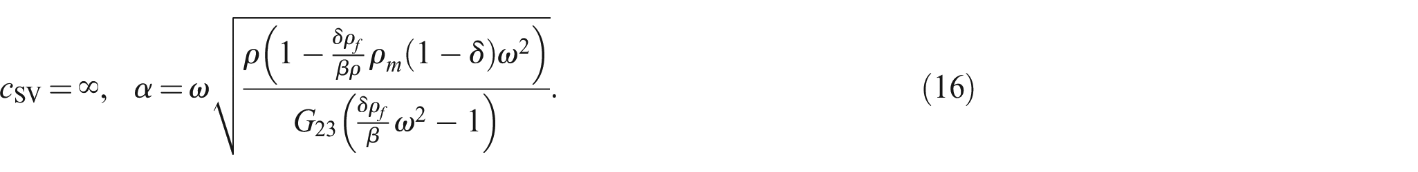
On the other hand, outside the bandgap, we have α = 0, and the transverse phase velocity cSV for SV-waves decreases with increasing ω in two separate ranges, below or above the bandgap, respectively,
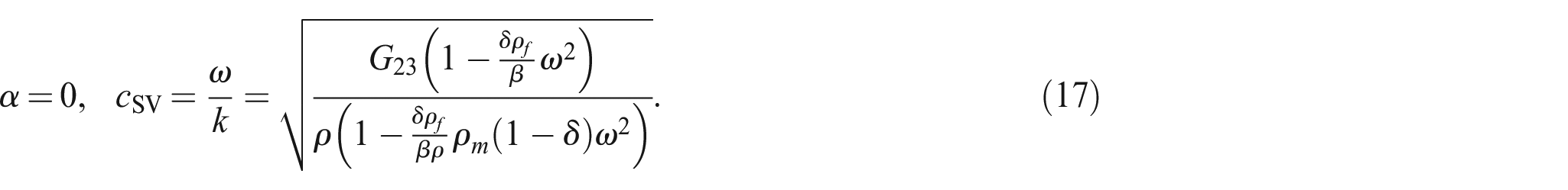
In particular, for low frequencies well below the bandgap, the phase velocity cSV is given approximately by,

For high frequencies well above the bandgap, we have,

The phase velocity cSV and the attenuation of plane SV-waves predicted by the present model are qualitatively similar to those of plane P-waves, as shown in Figures 2(b) and 3(b). A more detailed quantitative comparison of the present model with known data on SV-waves will be made in section 4.
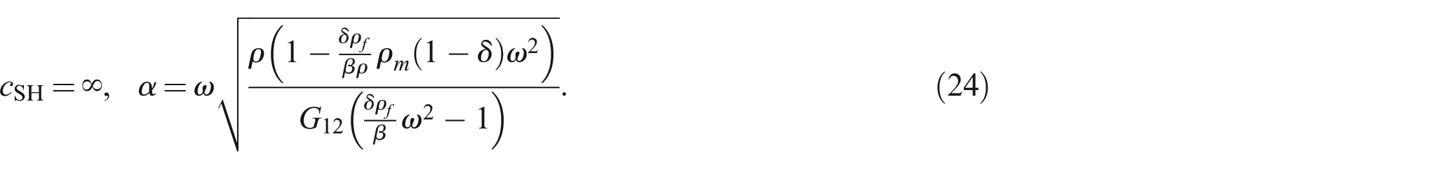
3.3. Anti-plane SH-waves
For anti-plane deformation w(x2, x3, t) with u = v = 0, the stress–strain Hookean law gives (see Appendix 1),

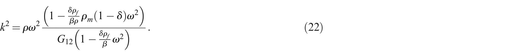
For SH-wave propagating along x2-direction, we have w(x2, t) =w0e-i(kx2-ωt) with a constant w0, thus

Thus, we have,
Within the following range of frequencies (called the “bandgap” for SH-waves under anti-plane shearing, see Appendix 2) defined by,

We have,
On the other hand, outside the bandgap, we have α = 0, and the phase velocity cSH for SH-waves decreases with increasing ω in two separate ranges, below or above the bandgap, respectively,
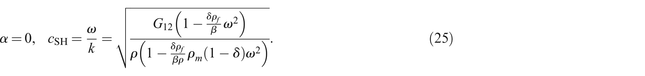
In particular, for low frequencies well below the bandgap, the phase velocity cSH is given approximately by,

For high frequencies well above the bandgap, we have,

Thus, the phase velocity cSH and the attenuation of plane SH-waves predicted by the present model are qualitatively similar to those of plane P-waves and SV-waves, as shown in Figures 2(b) and 3(b). A more detailed quantitative comparison of the present model with known data on SH-waves will be made in section 4.
4. Comparison with known data
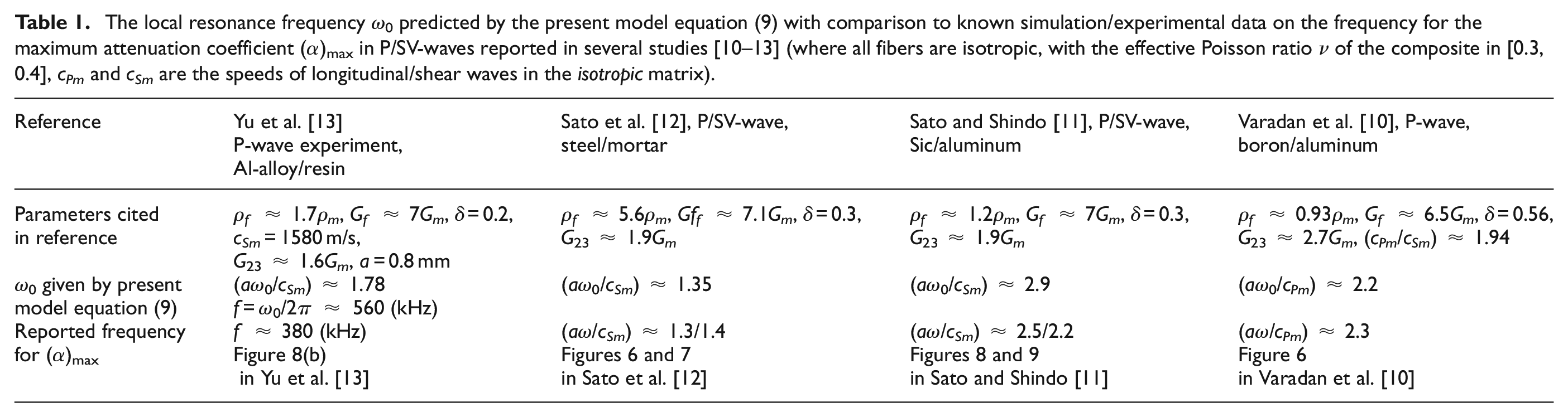
To demonstrate the efficiency and reasonable accuracy of the present model, let us make a detailed quantitative comparison of the results predicted by the present model with some known data published in past decades. Since most experimental data and numerical simulations show that the variation of phase velocity with frequency is relatively minor (usually not more than 10%–20%), the specific frequency at which the maximum attenuation appears is of major interest. Therefore, the local resonance frequency ω0 predicted by equation (9) for P/SV-waves and the local resonance frequency ωw predicted by equation (23) for SH-waves will be compared to the known data on the frequency for the maximum attenuation.
4.1. The frequency for the maximum attenuation (α)max
The local resonance frequency ω0 predicted by equation (9) is compared to the frequency for the maximum attenuation in P/SV-waves reported by more accurate numerical models and experiments, as shown in Table 1. The local resonance frequency ωw predicted by equation (23) is compared to the frequency for the maximum attenuation in SH-waves reported by more accurate numerical models, as shown in Table 2.
The local resonance frequency ω0 predicted by the present model equation (9) with comparison to known simulation/experimental data on the frequency for the maximum attenuation coefficient (α)max in P/SV-waves reported in several studies [10–13] (where all fibers are isotropic, with the effective Poisson ratio ν of the composite in [0.3, 0.4], cPm and cSm are the speeds of longitudinal/shear waves in the isotropic matrix).
The local resonance frequency ωw predicted by the present model equation (23) with comparison to known simulation data on the frequencies for the maximum attenuation coefficient (α)max for SH-waves reported in several studies [17–21] (where all fibers are isotropic, and cSm is the speed of shear waves in the isotropic matrix).
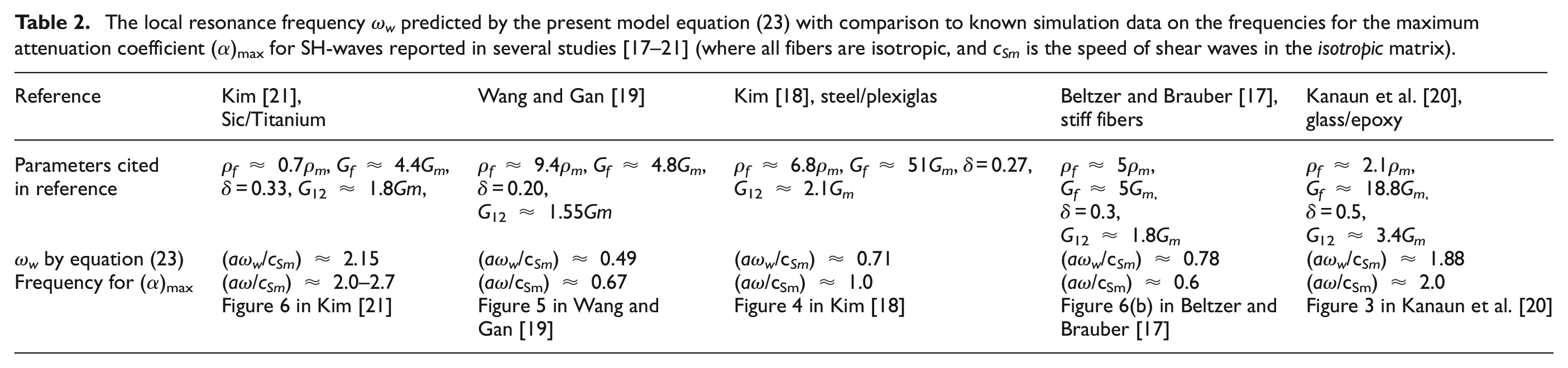
In view of the fact that the existing numerical models often give quite scattering data (typically, with 20%–30% or even larger relative errors between different models) for the frequency of maximum attenuation, it is reasonable to conclude from Tables 1 and 2 that the local resonance frequency ω0 or ωw predicted by the present model equations (9) or (23), for P/SV-waves or SH-waves, respectively, is in reasonable agreement with the known data on the frequency for the maximum attenuation (α)max, consistent with the concept that the local resonance of embedded fibers dominates wave attenuation of stiff unidirectional fiber-filled elastic random composites. In particular, the present model gives the same local resonance frequency equation (9) for P-waves and SV-waves, reasonably consistent with most known data, for instance, the simulation results of Sato and his colleagues [11,12] cited in Table 1 which show that the two frequencies for the maximum attenuation of P-waves and SV-waves are close to each other.
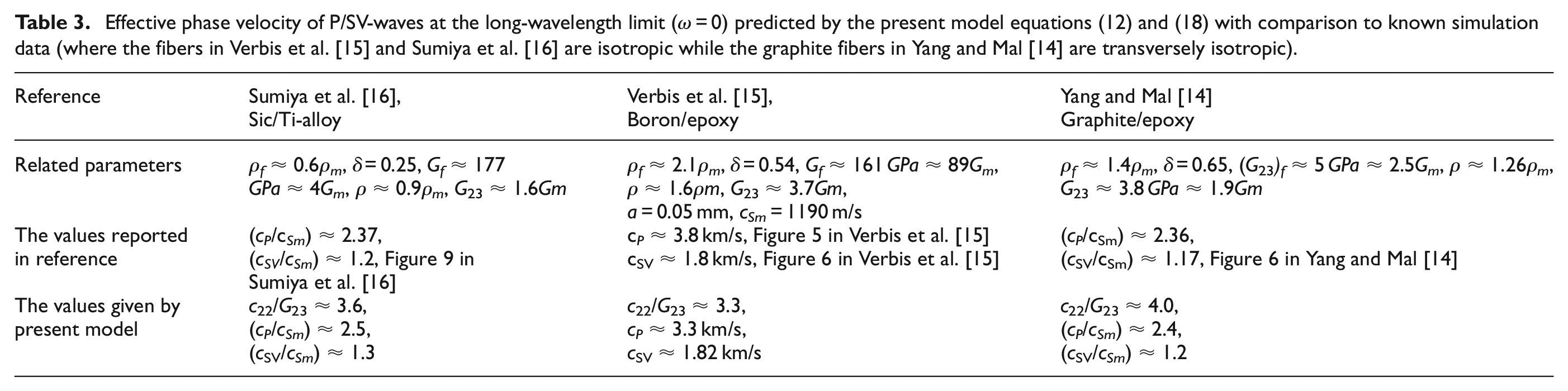
4.2. Phase velocity at low frequencies
In addition, some previous works have focused on lower frequencies well below the bandgap. In such a case, the present model predicts that the attenuation vanishes (α = 0), in agreement with known numerical simulations which showed that the attenuation at frequencies well below the bandgap is at least 2–3 orders of magnitude smaller than the maximum attenuation. Therefore, for frequencies well below the bandgap, let us focus on the effective phase velocity of the composites.
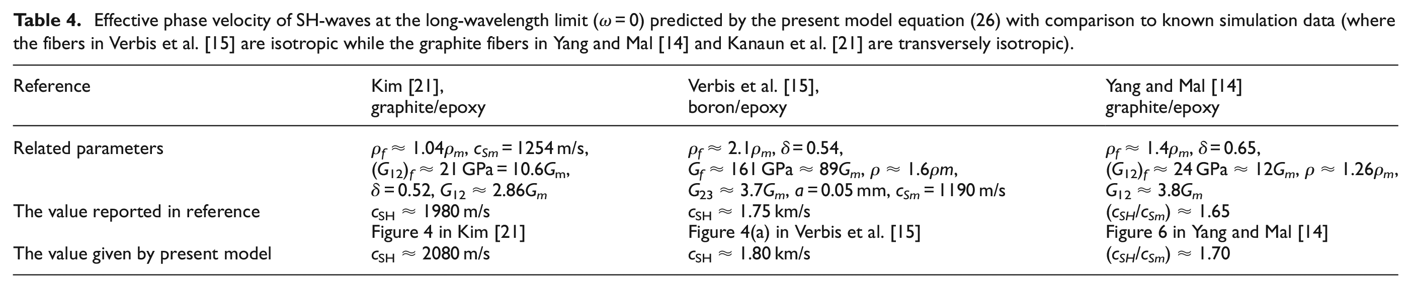
For example, the effective phase velocities at the long-wavelength limit (ω = 0) predicted by the present model, equation (12) for P-waves, equation (18) for SV-waves, and equation (26) for SH-waves, are compared with known data, as shown in Tables 3 and 4, respectively. Again, it is concluded from Tables 3 and 4 that the effective phase velocity predicted by the present model for frequencies well below the bandgap is generally in reasonable agreement with known data.
Effective phase velocity of P/SV-waves at the long-wavelength limit (ω = 0) predicted by the present model equations (12) and (18) with comparison to known simulation data (where the fibers in Verbis et al. [15] and Sumiya et al. [16] are isotropic while the graphite fibers in Yang and Mal [14] are transversely isotropic).
Effective phase velocity of SH-waves at the long-wavelength limit (ω = 0) predicted by the present model equation (26) with comparison to known simulation data (where the fibers in Verbis et al. [15] are isotropic while the graphite fibers in Yang and Mal [14] and Kanaun et al. [21] are transversely isotropic).
In addition, for frequencies well below the bandgap, phase velocity predicted by the present model decreases very slowly with increasing frequency. For instance, it is seen from equations (12), (18), and (26) that when frequency increases from ω = 0 to ω = ω0/2 (for P/SV-waves) or ω = ωw/2 (for SH-waves), the ratio of the decrease in phase velocity to the phase velocity at
5. Conclusion
A direct method is proposed to study wave propagation in stiff unidirectional fiber-reinforced elastic random composites. Compared to existing analytical or numerical models, the present model highlights the role of local resonance of embedded stiff fibers and enjoys conceptual and mathematical simplicity and the generality. The governing equations of the present model are given by a modified form of classical equations of elastodynamics (in which the inertia term is replaced by the acceleration field of the mass center of the representative unit cell) coupled with a simple differential relation between the displacement field of the mass center of representative unit cell and the displacement field of the composite. The efficiency and reasonable accuracy of the present model are demonstrated by good agreement between the predicted results and a large group of known data on the frequency for the maximum attenuation and the effective phase velocity at lower frequencies. The proposed model could offer a new general method to study various dynamic problems of stiff unidirectional fiber-reinforced elastic random composites, and an extension of the present method to hard sphere-reinforced elastic random composites will be studied in future work.