
Abstract
Composite material properties are dependent on their microstructure. To adequately model these microstructural effects, a formulation of elasticity that accounts for microstructural effects must be considered. Size-dependent behaviour is an inherent property of such materials, resulting in a need for non-classical continuum theories for adequate characterization. A three-dimensional model for an exponentially graded composite with microstructural effects is developed under the framework of Cosserat elasticity. The mixed boundary value problem is formulated and solved through the finite element method, and implemented in the commercial software Abaqus through two user developed elements. Recovery of the classical limit for the Dirichlet problem is discussed as an initial model validation until complete experimental measurements can be conducted.
1. Introduction
Composites are materials in which two or more constituent materials are combined to form a continuum. The resulting mixture possesses material properties different to the individual components, with many composites being tailored for specific applications. Some examples of composites include concrete, rubber, and polycrystalline aggregates [1], with the majority of applications appearing in the automotive, aviation, and construction sectors.
Due to the difference in the properties of the composites constituents, the nature in which they are combined significantly influences the mechanical behaviour of the new material. Functional grading has become a topic of great interest due to the manufacturers ability to design the mechanical properties of the material to suit the desired application. Functional grading involves creating a gradient in the homogenized material properties to achieve the desired behaviour as a function of position. The mixture of the constituents can be altered using various methods, most notably using volume fraction, to achieve the gradient in properties that result in the desired behaviour.
Common functional grades include stepwise, power law, polynomial, exponential, and periodic. Examples of functionally graded composite materials include high performance sports equipment, human bone, and thermal shielding. Composite materials that do not have a functional grading, but rather are a perfect mixture of the constituents, can be considered as functionally graded materials with constant grading. Due to the rising interest in these materials and their applicability to future structural components, there is a fundamental need to understand their behaviour.
Many composites hold a microstructure that is statistically uniform (fibre and matrix), resulting in a macroscopically homogeneous material [2]. Such composite materials typically fail under significant loading conditions through the separation of the fibres and matrix—known as delamination or debonding [3,4]. The delamination is a result of significant shear stresses occurring at the interface where the constituents with differing properties are bonded [5]. Modelling of the debonding processes in such materials is challenging due to interface conditions, typically involving high stress concentrations.
Recently, functionally graded materials (FGMs) have been used in an attempt to solve the issue of debonding due to stress concentrations. By varying their elastic properties with position, FGMs create a smooth gradient that eliminates high stress concentrations and interface conditions [5]. The elimination of these sharp interfaces, where failure is typically initiated, creates a material with desirable properties [4,6] that can withstand extreme conditions (high temperature gradients and stress concentrations) [3,7,8]. FGMs are classified as microscopically heterogeneous materials due to the gradients that dictate their macroscopic properties [4,9]. In practice, the desired properties are obtained by spatially varying the volume fractions of the constituents in a preferred direction.
Since composite materials are heavily dependent on their microstructure, and several experiments have shown an inability of classical theory to capture these effects [10–19], a formulation of elasticity that accounts for microstructural effects must be considered. Adequate characterization of such materials necessitates non-classical continuum theories since size-dependent behaviour is inherent to them.
To attempt to supplement classical elasticity theory and account for experiments in which microstructural effects prevail, the micropolar (Cosserat) theory of elasticity has experienced a re-emergence. Mora and Wass [20] state that Cosserat elasticity is a good foundation for characterizing materials that exhibit these effects, since it includes higher order effects that are not present in classical continuum theories. These effects consider force-like quantities that develop in bodies when strain gradients exist, and consider rotations on the microstructure scale as kinematically independent from displacement. By incorporating these effects, Cosserat elasticity inherently includes a length scale [21] in its formulation, which can account for the observed size effects. This enriched model considers 6-degrees of freedom, the three classical displacements, as well as three microrotations (pointwise orientation). The spatial gradients of these rotations result in internal curvature measures, referred to as twist, which form work conjugates [22] to the resulting internal bending moments.
Furthermore, equilibrium of a material point includes a transfer of moments in addition to axial forces, which gives rise to the aforementioned kinematically independent microrotations. Considering moment equilibrium for a body, the addition of microrotations gives rise to stress-like quantities [23], known as couple stress, which consist of a couple per unit area. The inclusion of couple-stress terms in the moment equilibrium equations result in the stress tensor being asymmetric, contrasting classical stress tensors which can be simplified using Voigt (symmetric) notation.
This paper considers formulating the three-dimensional governing equations of Cosserat elasticity for an exponentially graded material with microstructure. The associated variational problem is constructed, and solved using the finite element method. Exponential grading is considered to demonstrate the formulation and solution procedure; however, any grading method can be used in conjunction with the presented procedure. The solution is then implemented in the commercial software Abaqus [24] by means of a user defined element (UEL). Experimental data containing measurements of Cosserat elastic constants are lacking, and as such complete experimental validation remains elusive until adequate measurements are made. Until such a time when adequate measurements are made, experimental validation is limited to recovery of the classical limit.
2. Preliminaries
Throughout what follows, tensor and index notation are utilized to describe the necessary functions. The tensors used cover three dimensions with indices assuming values 1, 2, and 3. Repeated indices denote a summation from 1 to 3 as per the Einstein summation convention, unless stated otherwise.
Consider a general Cosserat elastic body that occupies a domain

and a microrotation vector, containing kinematically independent microrotations about each axis:

where

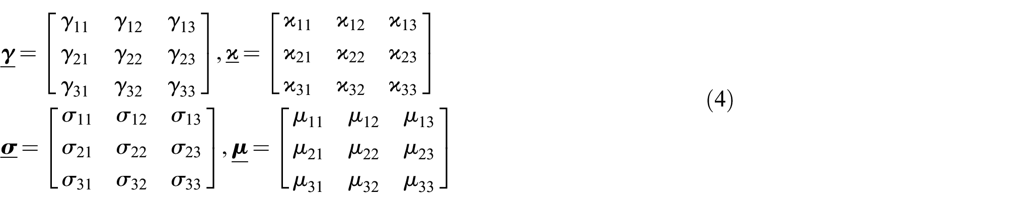
One can then extract the states of strain, twist, stress, and couple-stress [25], defined, respectively, as
Next, the equilibrium equations are formulated in terms of the defined tensors. Considering force and moment equilibrium, one obtains

where
The presence of the couple stresses in the formulation of micropolar media introduces asymmetry to the stress and couple-stress tensors. Furthermore, the asymmetry of the tensors in the governing equations for a micropolar solid results in a more complicated formulation. It is also important to note that in the absence of couple stresses, the above equations reduce to the classical formulation.
From these governing equations, one can extract basic relations between the quantities of interest. Namely, one can derive relations between the deformation tensors (strain, twist) and the corresponding degrees of freedom (displacements and microrotations in

The constitutive law for a general, anisotropic, and homogeneous micropolar elastic body proposed by Eringen [26,27] is given by

where
Considering an isotropic material,

where
Applying the isotropic tensors to the stresses yields the final form for a linear isotropic micropolar material,


In an FGM, the elastic constants, and consequently, the associated engineering constants, are functions of position, with the constants in an exponentially graded material written as


where
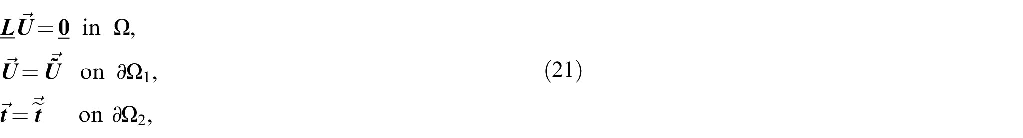
where
The equivalent variational formulation of the equilibrium equations is presented, such that
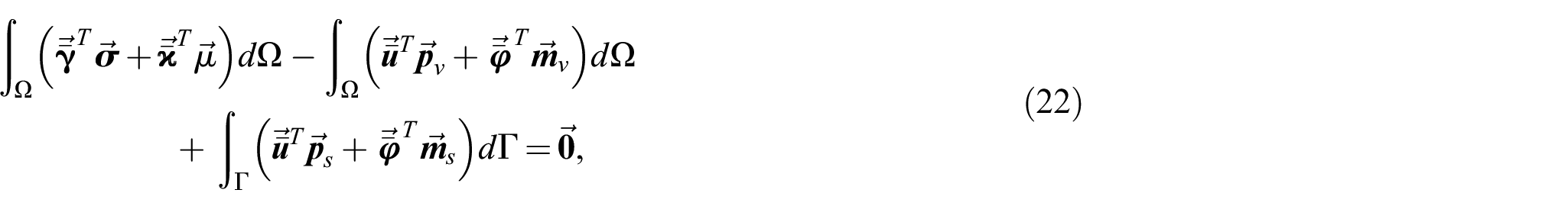
where
3. Finite element discretization and implementation into commercial software
3.1. Finite element formulation
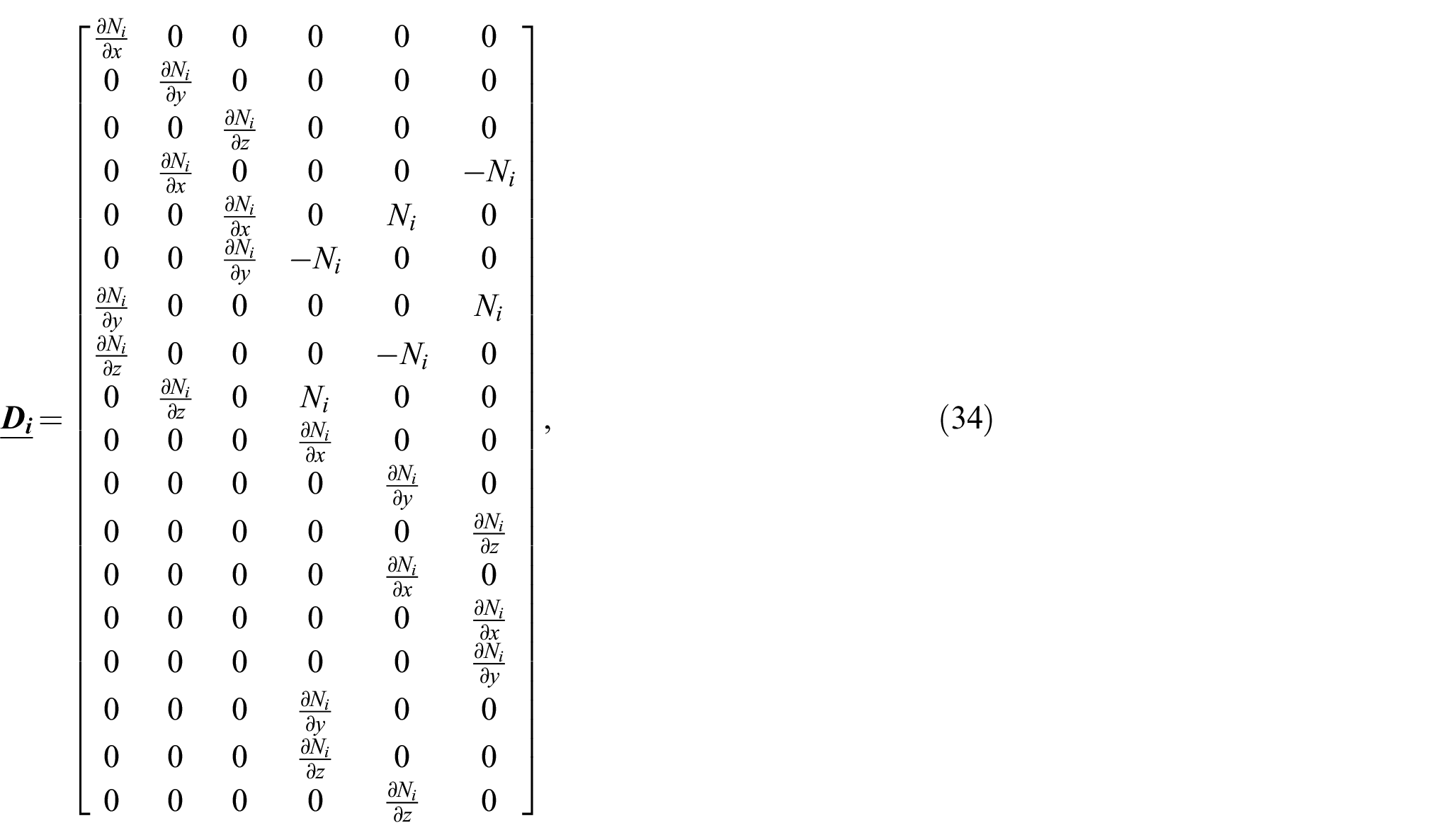
To simplify the expressions for use in the finite element method, some grouping of vectors is introduced.
First, the degrees of freedom are grouped such that

Following the grouping of the strains, the corresponding stresses are grouped such that

Considering the constitutive laws for a linear elastic Cosserat material with central symmetry, defined in equations (13) and (14), the expressions


can be grouped such that

Finally, the body and surface stresses and couple stresses are grouped such that

Due to the varying material properties within a functionally graded continuum, careful consideration is required in selecting the appropriate elements. Martínez-Pañedas [29] work on functionally graded finite elements suggests a need for quadratic elements to avoid introducing error related to non-linearly varying elastic properties. As such, quadratic, isoparameteric elements are considered. To properly discretize both simple and complex geometries, two elements are constructed: A quadratic, 20-noded isoparametric quadrilateral, and a quadratic, 15-noded isoparametric wedge. In what follows, the standard isoparametric approximations for the nodal degrees of freedom are used, such that


where

and
represent matrices containing the element shape function

and
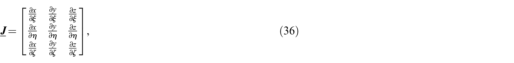
Furthermore, the chain rule used to relate differentiation in the global system to differentiation in the local system is given by
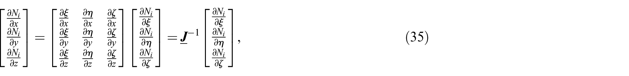
where the Jacobian matrix of transformation
Substituting the definitions into the variational formulation yields the familiar finite element formulation

where


and where
3.2. Finite element implementation
User-defined material behaviour is typically implemented in Abaqus [24] in the form of a user-defined material subroutine (UMAT). The material behaviour is then incorporated into an element definition selected from the Abaqus element library. Such elements are not suitable for Cosserat analyses, as the 3 additional kinematically independent degrees of freedom (microrotations) are not accounted for in the available library of elements. To establish a dedicated Cosserat element as a foundation for future works, this work instead constructs a user element using the UEL subroutine.
The UEL subroutine defines all the relevant quantities for element computations, and can include a constitutive update to avoid having to define a separate user material. Visualization of the results is an area of concern with user defined elements, as Abaqus is incapable of natively displaying contour plots for quantities of interest, other than the three classical nodal displacements. Abaqus employs Voigt notation to define stresses, which renders its native output database structure unsuitable for the storage of results of elements with asymmetric stress states.
The issue of contour plot visualization is circumvented by Shi et al. [30] through the use of a ghost mesh approach, where the results from the user material simulation are overlaid onto the results form another simulation in which the material had negligible elastic properties. While this approach allows for native visualization of user elements that hold the same degrees of freedom as the available elements in the Abaqus library, it does not solve the issue for elements with additional degrees of freedom. Another approach by Eremeyev et al. [31] overcomes the issue of asymmetric stress storage by generating three output databases, storing 6 of 18 stress/couple-stress components in each, and keeping track of the variables manually. While effective, this approach can present some confusion to the user. This work instead bypasses the Abaqus output database altogether, writing the desired output to a series of comma separated value (CSV) files for post-processing.
A post-processing code is developed in Python, which reads the input file used for simulation, as well as the generated CSV output, and uses object oriented programming to replicate the output database hierarchical structure that Abaqus employs. The processed data is written to a series of VTU (virtual toolkit) files which can be viewed in open source visualization software such as Paraview. The approach used to write the VTU files is based on the approach by Liu et al. [32].
3.2.1. 20-noded quadrilateral
The 20-noded isoparametric quadratic quadrilateral element is designed with the nodal coordinates shown in Figure 1. The chosen node numbering follows the convention employed by Abaqus to facilitate integration into the software.
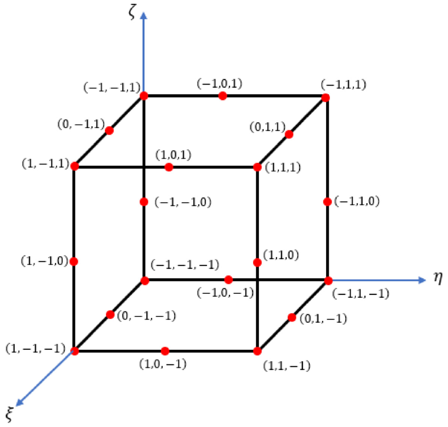
Nodal locations in local coordinate system for quadrilateral element.
The associated shape functions are presented for reproducibility (following Abaqus’s convention) and take the form


in the natural coordinate system, where
3.2.2. 15-noded wedge
To construct a 15-noded isoparametric quadratic wedge element, in a similar manner to the quadrilateral element, the node numbering convention used by Abaqus is followed, and the nodal coordinates can be seen in Figure 2. The associated shape functions are presented for reproducibility (following Abaqus’s convention) and take the form


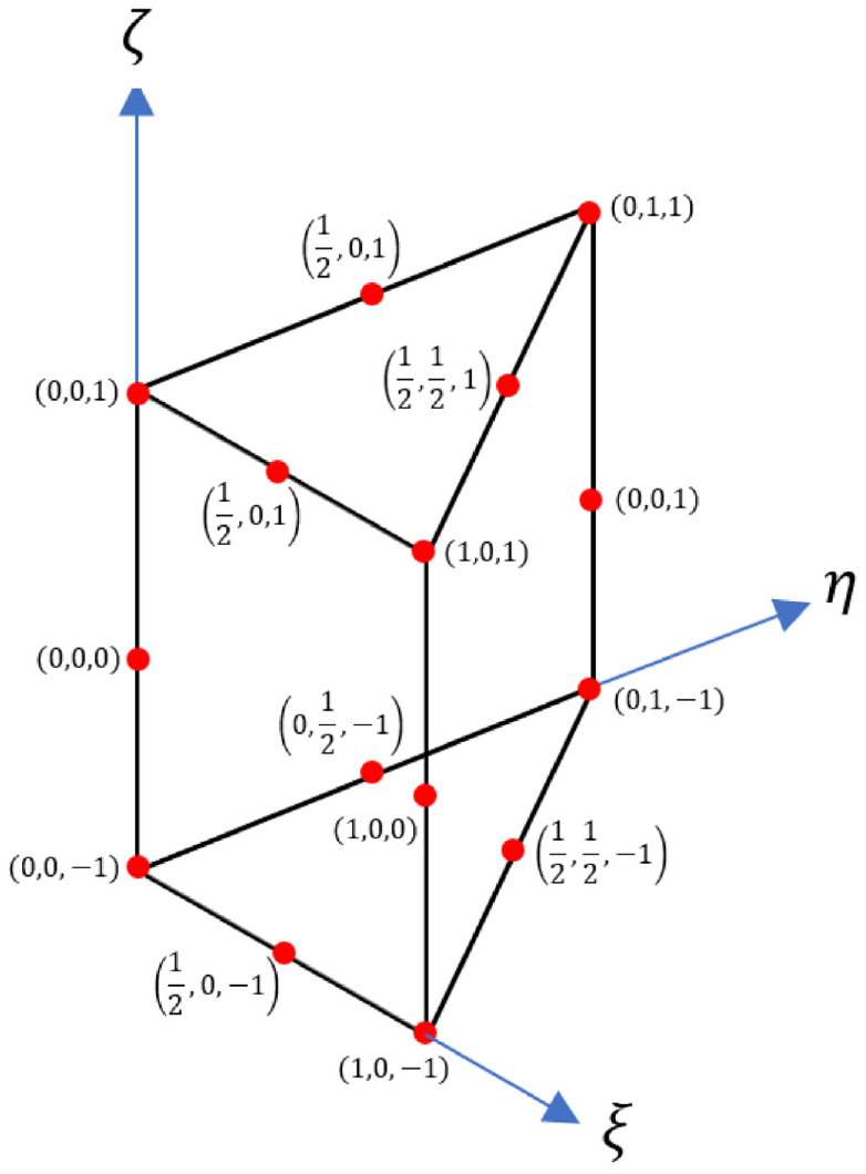
Nodal locations in local coordinate system for wedge element.
To numerically integrate the relevant quantities, a nine-point formula for integration over triangular domains is used, and extended to three dimensions using the eight-point rule for the quadrilateral. The approach for quadrature over triangles is outlined in Cowper et al. [33].
4. Numerical examples—classical limit
Typically, verification of solutions to finite element analyses requires comparison with experimental tests. While measurement tools are becoming more refined as the field of nano fabrication expands, testing and measurement of microrotations are currently difficult due to the size at which measurements must take place. Until such a time where these measurements become more commonplace, verification of the designed user elements, and by extension the solution to the formulated boundary value problems, involves recovery of the classical limit. Such a verification only provides a foundational step to establishing the model as an analysis tool, as a full verification can only be performed once the aforementioned measurements can take place. Nevertheless, recovery of the classical limit is an important first step.
To verify the recovery of the classical limit, the Cosserat elastic constants (
In all comparisons, the individual displacement components, as well as stress components, are compared to ensure the classical limit is recovered. To ensure an adequate comparison, the same boundary conditions are employed in both models, with the addition of setting the 3 microrotational degrees of freedom to 0 in the user element. Throughout what follows, the Dirichlet problem is solved, with prescribed displacements imposing the required loading scenario. All displayed units are measured in

4.1. Quadrilateral element assembly
The solution to the Dirichlet problem for a quadrilateral element assembly comprising 27 quadrilateral elements (representing a
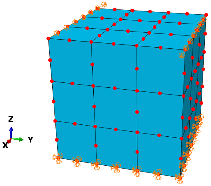
Boundary conditions and loading for 27 element quadrilateral element assembly (user/C3D20) in torsion.
Figures 5–7 (in Appendix 1) compare the displacement components, normal stresses, and shear stresses of the user element assembly to an equivalent C3D20 element assembly at the final analysis increment. The numerical values corresponding to the compared solutions displayed in Figures 5–7 (in Appendix 1) are identical up to Single Precision order. As such, all displacements are accurate to nine significant digits.
4.2. Wedge element assembly (cylinder)
The solution to the Dirichlet problem for a cylindrical wedge element assembly comprising of 36 wedge elements (representing a
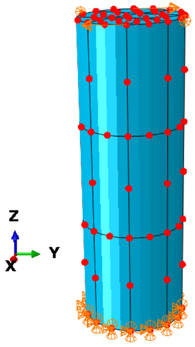
Boundary conditions and loading for 36 element cylindrical wedge element assembly (user/C3D15) in torsion.
The numerical values corresponding to the compared solutions displayed in Figures 8–10 (in Appendix 1) are identical up to single precision order (accurate to nine significant digits), completing the recovery of the classical limit in the case of torsion for assemblies of the designed elements. While not presented in this work, the cases of uniaxial compression loading and shear loading also result in recovery of the classical limit, maintaining single precision accuracy.
5. Numerical example—conceptual case
To demonstrate a conceptual application of the model, a case in which fictitious material parameters are used is considered. The Dirichlet boundary value problem in equation (60), in the case of torsion loading (Figure 4) for the cylindrical wedge assembly is once again considered. The material elastic constants considered are
Figure 11 (in Appendix 1) displays a comparison of the magnitude of the stress vector for all four considered cases. A notable localization of stresses occurs in the case with only Cosserat effects at the loading nodes, with a more significant localization occurring at the loading nodes in the direction of grading in the case with both exponential grading and Cosserat effects.
The localized rotations at the load application nodes induced by the torsional loading give rise to significant differences between the classical predictions and Cosserat predictions. The most significant differences between classical and Cosserat predictions are therefore likely to arise in load cases where the loading induces more significant nodal rotations; this corresponds to the cases of torsional and shear loading, as opposed to compression loading.
A comparison of the numerical values for the magnitude of the stress vector highlights the differences between the material models, with the introduction of Cosserat effects only presenting a 270% increase in maximum magnitude (redistribution and localization). Similarly, exponential grading only offers a 45% increase in maximum stress magnitude from the classical case, as the stresses are localized in the direction of the grading. Introducing both effects results in a similar increase from the classical case, with the peak magnitudes being 24, 90, 35, and 110
6. Discussion
A three-dimensional, linear elastic, isotropic model for a functionally graded composite material is developed, and presented as a mixed boundary value problem. The model considers microstructural effects through Cosserat elasticity. The associated variational (weak form) formulation is presented and used to discretize the problem through the finite element method. Two quadratic elements (20-noded quadrilateral, 15-noded wedge) are developed and implemented in Abaqus through the UEL subroutine.
Preliminary validation of the elements through recovery of the classical limit in the Dirichlet problem is conducted in the cases of uniaxial compression, shear, and torsion loading, with the torsion loading case presented as a representative case. All displacements are accurate up to single precision order (nine significant digits).
Future availability of experimental measurements of microrotations allows for complete validation of the model, and its use as an analysis tool. Exponential grading is presented in this work; however, any chosen grading scheme can be used with the presented method. For alternative grading schemes, careful consideration must be put into the selected quadrature scheme to ensure an accurate response.
A demonstration of the applicability of the model is presented through the use of fictitious elastic parameters, demonstrating notable differences in the responses when compared to the classical case. The differences arise in the form of stress localization, in particular at the load application nodes, and in the direction of functional grading.
Footnotes
Appendix 1: comparison of nodal stresses and displacements for presented numerical examples
Declaration of conflicting interests
The author(s) declared no potential conflicts of interest with respect to the research, authorship, and/or publication of this article.
Funding
The author(s) disclosed receipt of the following financial support for the research, authorship, and/or publication of this article: The authors wish to thank Natural Science and Engineering Research Council of Canada for their financial support of this work.