
Abstract
Making use of experimental data for bias extension, shearing, and point-load tests in large deformation regime for rectangular and square bi-pantographic specimens, we perform a numerical identification to fit the a priori parameters of a planar discrete spring model. The main objective of the work is to develop an automatized optimization process based on the Nelder–Mead simplex algorithm for identifying the constitutive parameters of discrete modeling of bi-pantographic structures, as well as assessing its descriptiveness and predictive capacity. The analysis allows to conclude that there exists a single set of parameters for the adopted discrete modeling such that it is descriptive and predictive for several different tests and for a wide range of deformations.
Keywords
1. Introduction
This paper deals with a generalization of pantographic fabrics [1,2]. Pantographic fabrics are actual fabrics which are made up of two orthogonal families of parallel beams. Beams of different families are connected at their intersection points by means of perfect hinges or, alternatively, by means of elastic hinges, i.e., hinges and rotational springs opposing to the relative rotation of beams concurring to the same hinge. Within each family, beams are at a given distance between each other. Such a distance might be depending on the beam pair or be constant. If each family of beams contains the same number of beams, having the same constant distance one from each other, and the beams have all the same dimensions and physical properties, then the pantographic fabric is said to be balanced [3]. Pantographic fabrics were designed and then realized physically by arranging the two families of beams onto two different parallel planes. The design and realization of connections between two beams have been accomplished by means of cylindrical pivots acting ideally as in-plane elastic hinges, i.e., hinges with torsional springs [4,5], and by means of actual hinges which, however, are prone to suffering significant non-elastic phenomena and hence pose complex challenges in manufacturing engineering. While the realization of cylindrical pivots is less challenging from the manufacturing point of view—there are, however, issues related to the plane in which scanning tracks lie and heat treatments for metallic specimens—it has been proved by experimental and computational investigations that the behavior of cylindrical pivots involves complex deformation modes and, particularly, significant non-torsional deformation modes in large deformation. Beams in pantographic fabrics play the role of bending elements. Their utilization in pantographic fabrics has been conceived to confer to the fabric, when regarded as a continuum, second gradient effects in plane due to the dependence of the deformation energy upon the geodesic bending of the material lines. However, the presence of beams does not only entail these desired effects. The fact that in the physical reality beams are arranged on two different planes makes them interact mutually, in a way such that torsional deformation modes [6], as well as in-plane and out-of-plane buckling [7–9], are triggered, even when problems with in-plane boundary conditions are considered [10].
In the last years, many research efforts published in the scientific literature have dealt with variations and enhancements of the design of pantographic fabrics. As mentioned before, the design and manufacturing of perfect hinges in pantographic fabrics have been attempted in the context of three-dimensional (3D) printing using both metallic and polymeric raw material (see in this regard the works [11,12]). It is worth to mention in this introduction that also non-orthogonal families of fibers [13], as well as non-straight fibers [14], have been considered in the scientific literature. The need for performing and understanding experimental analyses on pantographic fabrics has stimulated many studies in Digital Image Correlation (DIC), manufacturing techniques, and material characterization [15–17]. It is worth to mention here that pantographic specimens have been realized also at extremely low scales, including the nano-scale [18–20].
Pantographic materials belong to a class of materials which includes not only pantographic fabrics but, more generally, materials with a microstructure based on the pantographic motif, i.e., a mechanism which is well known from everyday life (pantographic mirrors, expanding fences, scissor lifts, etc.), which is characterized by a zero-energy accordion-like homogeneous extension/compression deformation mode. For example, pantographic beams—namely, strips of pantographic fabrics consisting of the periodic repetition in one direction of a single pantographic cell—have been proposed as an example of complete second gradient beam [21–24]. In this paper, a particular kind of metamaterials is addressed, namely, the so-called Bi-Pantographic Structures (Bi-PSs). Bi-PSs were conceived as a generalization of pantographic fabrics and consist of pantographic fabrics whose beams have in turn a pantographic microstructure and are, actually, pantographic beams (see Figure 1). They were first introduced in the paper [25].
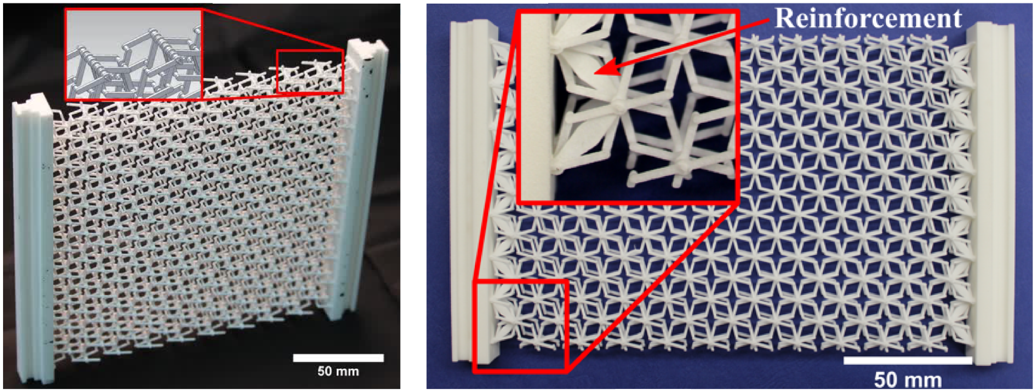
Quadratic Bi-PS (sample A1) with a CAD detail view of the inner structure on the left-hand side, developed by Barchiesi and colleagues [26,27], printed on a Formagia P 100 (EOS GmbH, Krailling, Germany) using SLS. A rectangle Bi-PS (sample B1) is shown on the right-hand side. The detail view shows a sample with different boundary conditions in order to achieve reinforcement.
One of the main advantages of additive manufacturing lies in the possibility of easily producing complex 3D geometries at, practically, no additional cost. For this reason, the development of 3D-printing techniques witnessed in the last two decades has stimulated research in the field of mechanical metamaterials. These materials assume special properties depending on their microstructure. However, while additive manufacturing is experiencing great progress in the number of raw materials that can be used, see as an instance the recent works on the 3D printing of concrete structures, the main raw materials used in additive manufacturing are still polymeric or metallic. When polymeric and metallic materials are considered, additive manufacturing and, particularly, powder bed fusion technology, can guarantee a final specimen quality which is comparable to standard manufacturing techniques. Actually, when metallic materials are considered, post-processing of specimens is still needed to remove residual stresses caused by temperature gradients during the printing phase.
Generally speaking, printed materials deposited in layers may exhibit anisotropic behavior, due to their lamellar structure, which needs to be evaluated. The interface between the layers, depending on the process, remains a sensitive area, which may represent the mechanically weak points of the structure. It is therefore necessary to establish a study methodology to characterize the complex and anisotropic behavior of this type of material to further improve existing additive manufacturing processes. However, even simple microstructures realized by means of 3D printing have been proven to result in material properties which are extremely interesting from the engineering viewpoint, like extension-bending/extension-torsion coupling [28–31], band gap properties for vibration attenuation [32,33], extreme stiffness [34], fluid-like behavior [35], extreme elastic range [36], damage-tolerant behavior [37], enhanced and/or tailored stability properties [38,39], unidirectional response [40,41], and many others [42].
It is evident that designing microstructures to be 3D printed, possibly by topological optimization techniques [43], requires a thorough quantitative understanding of the mechanical behavior of the structure to be printed. Continuum models are needed to describe the large-scale mechanical behavior of a wide class of materials that, at some spatial scale, possess a microstructure. These models are particularly important for bridging spatial scales ranging from that of interactions between elements of the microstructure to the collective behavior of a large number of elements [44]. In the last 10 years, making use of generalized and second gradient continua theories introduced in the early 1960s [45–47], many investigations were carried out dealing with pantographic structures. In particular, the paper [26] provided the first homogenization result for Bi-PS in large deformation regime along with numerical results and experimental measurements for validation purposes.
Discrete simulations can be designed that provide trajectories and distribution of strain energies at the element scale. Therefore, discrete models can be used as a more refined description than continuum models. While continuum models are less computationally demanding than discrete models, the formulation of continuum models able of capturing the behavior of a material with microstructure, as well as the development of robust numerical procedures [48,49] that work in sometimes-singular cases, is still challenging and, in any case, requires the utilization of discrete simulations for validation purposes. Therefore, when exploring the behavior of a material with microstructure, while less appealing in view of getting analytical expressions, the utilization of discrete simulations is of utmost utility. For the understanding of Bi-PS, the use of discrete simulations has been indeed beneficial. Discrete modeling has been used as microscale description for developing a homogenized continuum description of Bi-PS and, albeit not systematically as in the present work, its experimental fitting has been carried out, together with that of the homogenized continuum model, in the paper [27].
In this paper, motivated by the encouraging results obtained in Barchiesi et al. [27], making use of training and test sets of experimental data, a numerical identification [50–52] is performed to fit the parameters of a planar discrete spring model describing the static behavior of Bi-PS subjected to different kind of loads and boundary conditions. The model is fitted using force–displacement curves for bias extension, shearing, and point-load tests in large deformation regime for rectangular and square specimens. The attempt reported in this paper of performing a systematic fitting and validation procedure for Bi-PS is inspired from existing literature on the identification of models describing pantographic fabrics. In De Angelo et al. [53], the in-plane and out-of-plane stiffnesses of a continuum plate model are determined by simulating bias extension and shear tests and employing the Levenberg–Marquardt optimization algorithm. In Shekarchizadeh et al. [52], the numerical identification of the constitutive parameters of the aforementioned macromodel is carried out through the trust region reflective optimization method. Contrarily to this work, which makes use of experimental data, these two works made use of data generated by a refined 3D model based on Cauchy mechanics and hyperelastic constitutive laws.
Developing an automatized optimization process for identifying the constitutive parameters of discrete modeling of Bi-PS and testing its descriptiveness and predictive capacity are the main objectives of the work, which is organized as follows. Section 2 introduces the manufacturing technology employed to realize the specimens, the experimental setup, and the discrete modeling of Bi-PS via elastic springs. Section 3 illustrates the minimization problem to be solved by the gradient free Nelder–Mead simplex algorithm for determining an optimal set of model parameters on the basis of experimental measurements, and presents the results of the analysis. Finally, conclusions and outlooks are briefly sketched. Building on top of previous work, the analysis allows to conclude that there exists a single set of parameters for the adopted discrete modeling, which was also employed in previous papers as microscale model for homogenization purposes, such that it is descriptive of several different tests for a wide range of deformations and such that the model is predictive when experimental deformed shapes are compared with numerically computed ones.
2. Materials and methods
Two batches of specimens, listed in Table 1, consisting of three quadratic Bi-PS (sample family A, see left of Figure 1) and two rectangle Bi-PS (sample family B, see right of Figure 1), have been printed using a selective laser sintering (SLS) technique. Each sample family was tested in an extension test and shearing test (see Table 1). In addition, a so-called point-force test was applied to the quadratic sample (A3). Furthermore, a discrete simulation based on the Hencky-type model is going to be introduced. Its numerical results will be compared with experimental measurement data.
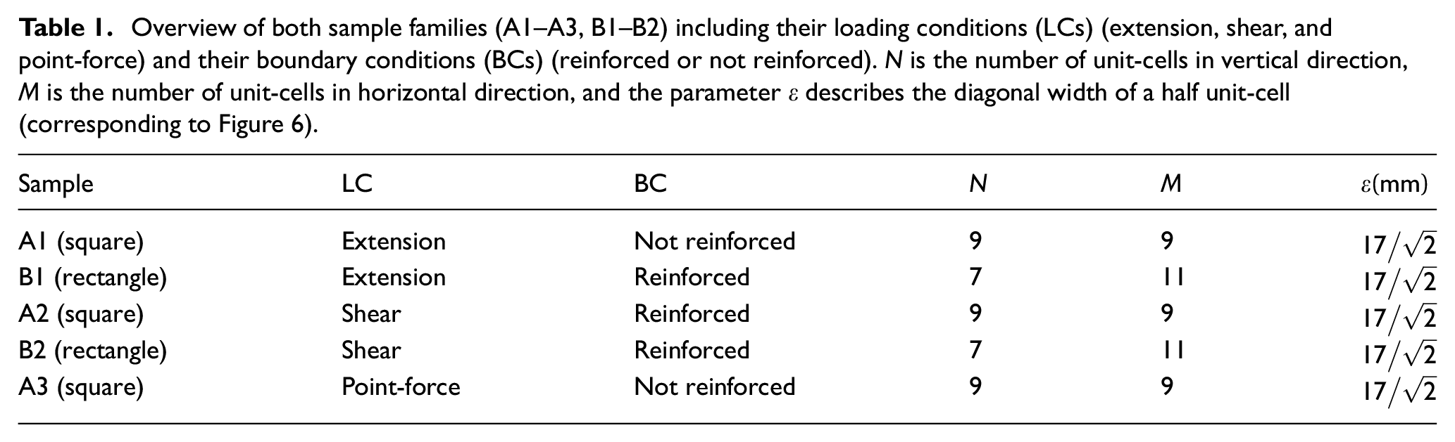
Overview of both sample families (A1–A3, B1–B2) including their loading conditions (LCs) (extension, shear, andpoint-force) and their boundary conditions (BCs) (reinforced or not reinforced). N is the number of unit-cells in vertical direction,M is the number of unit-cells in horizontal direction, and the parameter
All samples have been manufactured by means of SLS. Polyamide (PA) powder (PA 2200, EOS GmbH, Krailling, Germany) with an average grain size of 0.056 mm was fused in the commercial 3D printer EOS Formagia P 100 (EOS GmbH) located at the Institute of Mechanics and Printing, University of Technology Warsaw, Poland. In this bottom-up procedure, layers are sintered in the heated, focused laser spot. The specimen is manufactured layer-by-layer by means of a laser beam under inert gas atmosphere. After printing predefined points in the first layer, the table is lowered and shaken before new powder is applied by a wiper. The process repeats until the sample is finished. In order to reduce initial stresses, the sample has to cool down for several hours. All samples have been finished by means of a high pressure cleaner.
Printing results are shown in Figure 1. A square Bi-PS (sample A1) with a CAD detail view of the inner structure on the left-hand side and a rectangular Bi-PS (sample B1) on the right-hand side with a detail view of reinforcements can be recognized. In order to overcome the limits of lack of contrast and therefore to enable DIC for the determination of displacements during real-time deformation, both sample families have been speckled with black ink on the outer surface. CAD drawings with their inner and outer geometric parameters are shown in Figure 2.
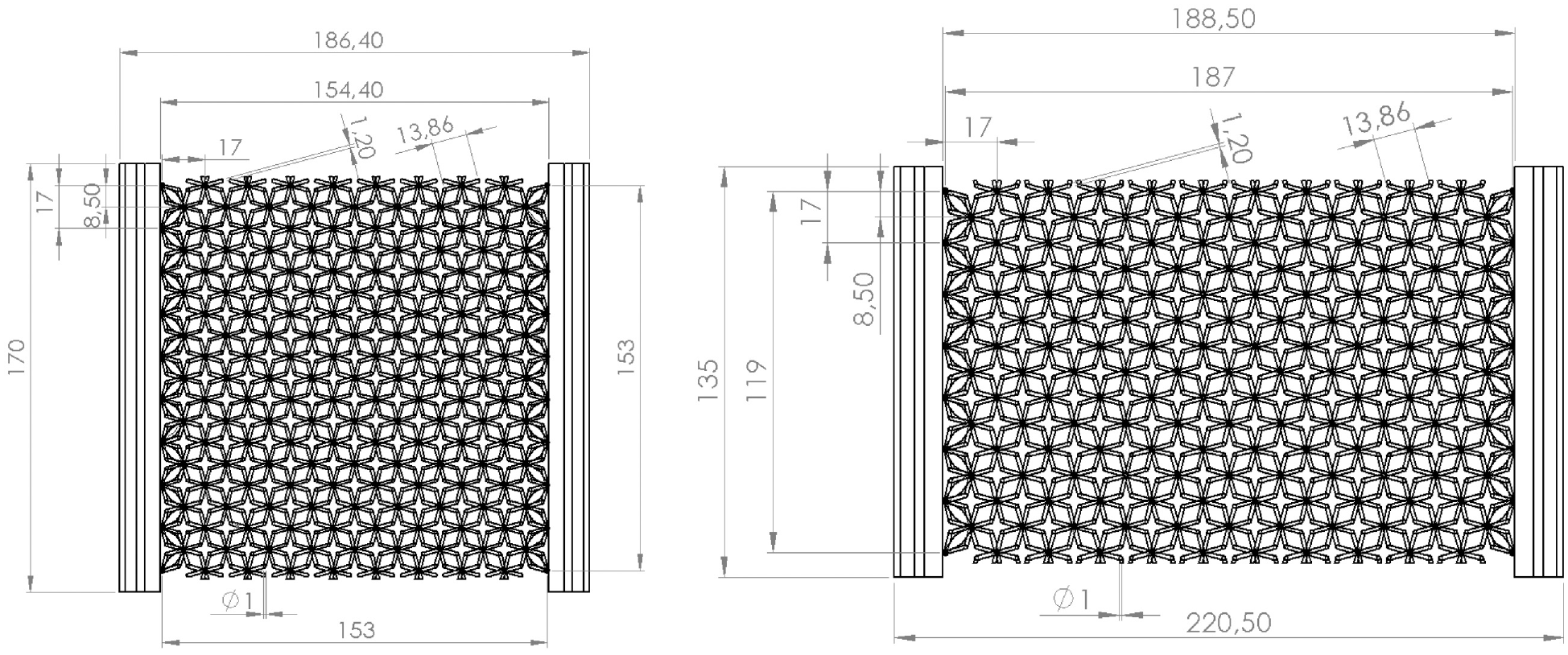
CAD drawings of a quadratic Bi-PS (specimen family A) and rectangle Bi-PS (specimen family B).
2.1. Experimental setup
All experiments have been performed on an MTS Tytron 250 testing device (MTS Systems Corporation, Eden Prairie, MN, USA) at the Institute of Mechanics, Technical University Berlin, Germany. Three different experiments have been performed: standard extension tests, shearing tests, and a so-called point-force test (see Table 1). Furthermore, in order to investigate the effect of reinforcements at the border of the inner substructure on the outer deformation behavior in more detail, different boundary conditions have been taken into account (see Table 1). By adapting a rigid body to the mounting side, a reinforcement was achieved (see detail view on the right-hand side of Figure 1). The schematics of the three different experimental setups are summarized in Figure 3.
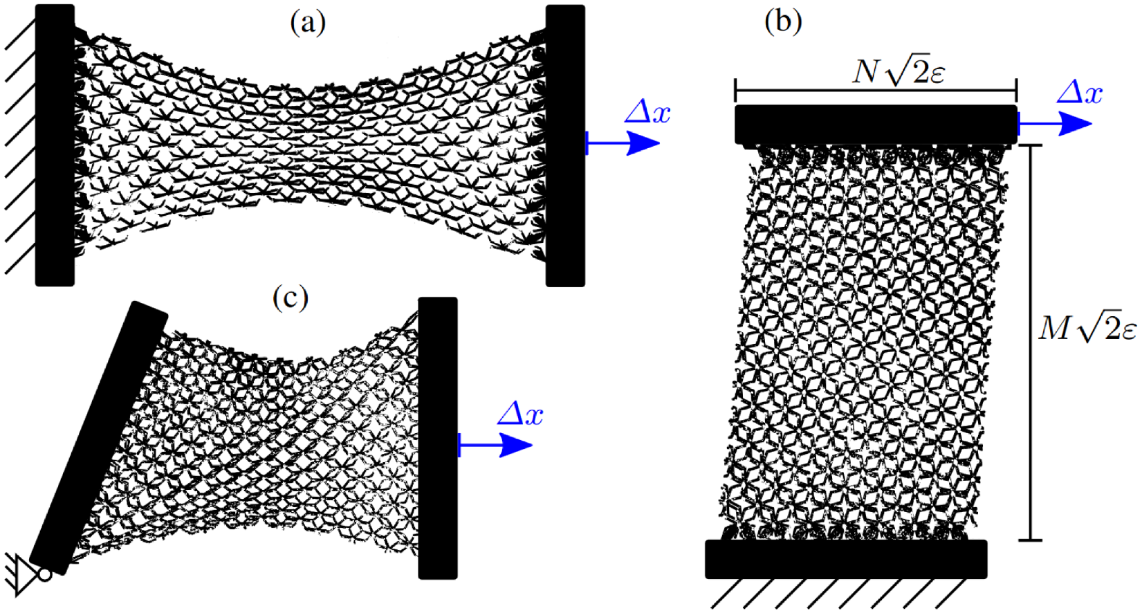
Schematics of displacement-controlled
As shown in Figure 4 for the case of extension load, maximal reaction forces were measured by a device-own loading cell with
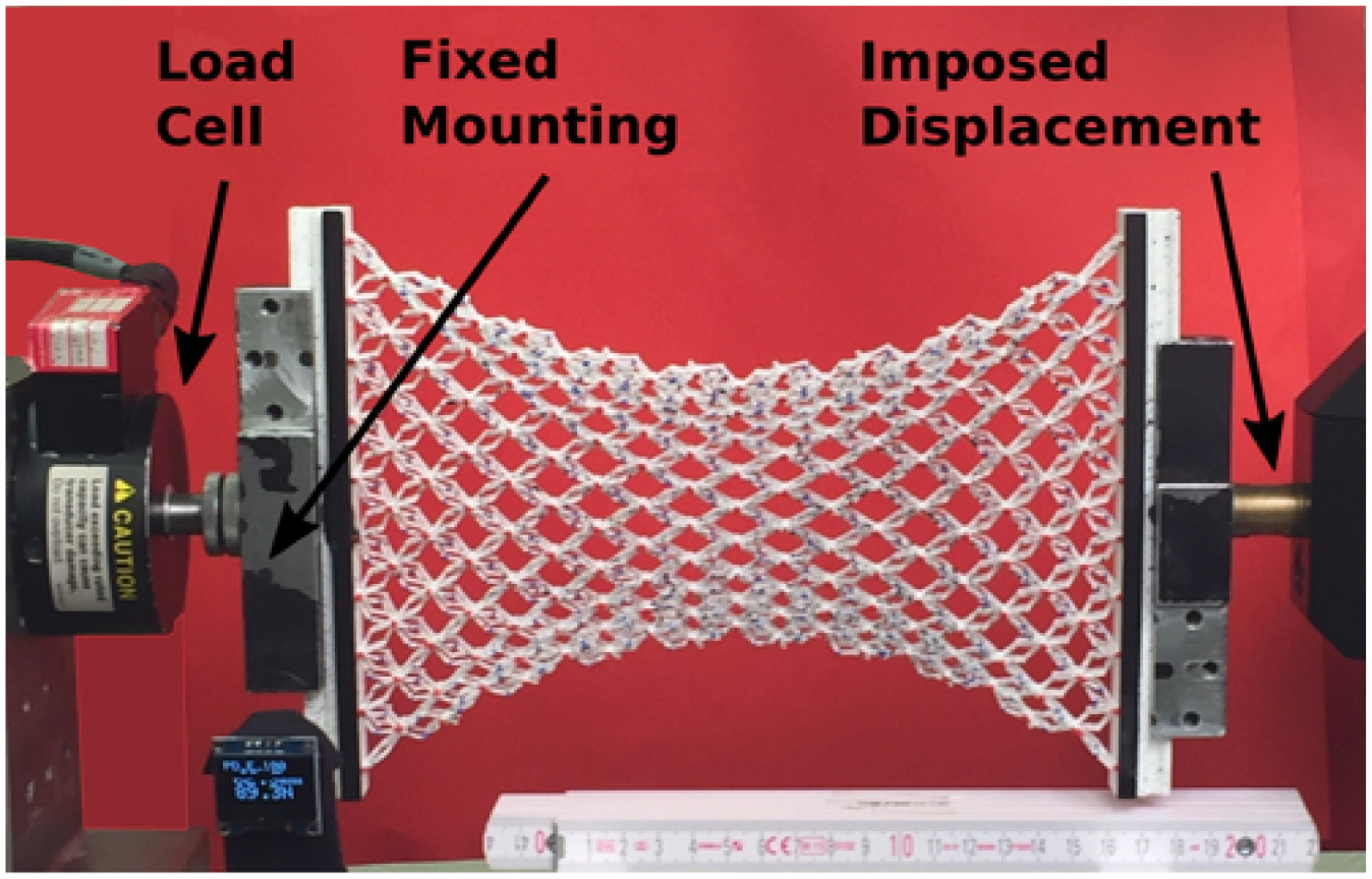
Extension test of a not reinforced quadratic Bi-PS (A1). Displacement
2.2. Discrete model
For solving the discrete micromodel, it is convenient to introduce a global, minimal set of generalized coordinates, such that the kinematics of the discrete system is entirely described by the coordinates of the nodal points. The bi-pantographic sheet is modeled as a discrete elastic spring system that is embedded in the 2D Euclidean vector space
The springs are formulated between nodal points, which are depicted as white filled circles (see Figure 5). The position

The derivative with respect to

Without loss of generality, we restrict ourselves to linear springs (cf. Andreaus et al. [54], equation (4)), which are modeled by means of a quadratic potential with stiffness

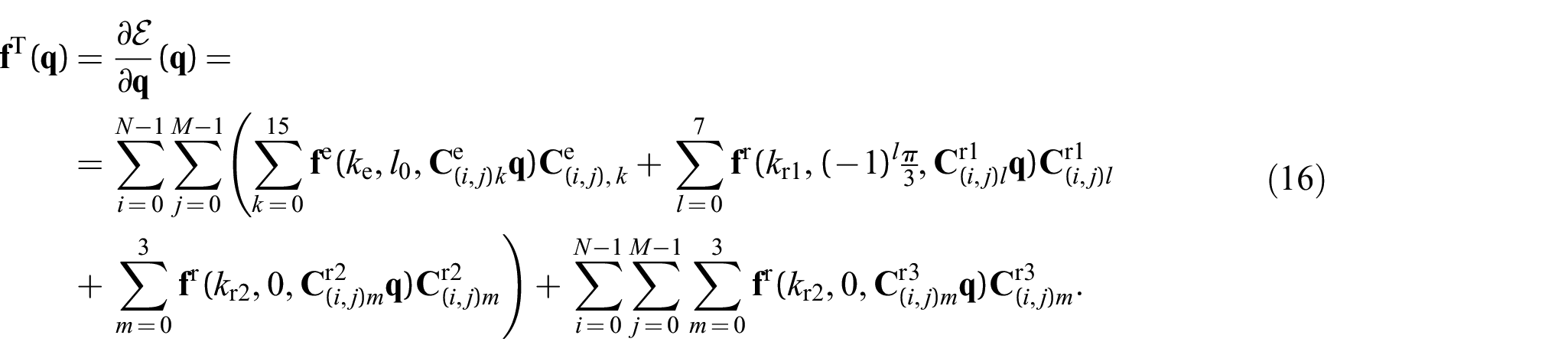
The derivative of the potential (3) with respect to

where the transposed of a matrix is indicated by
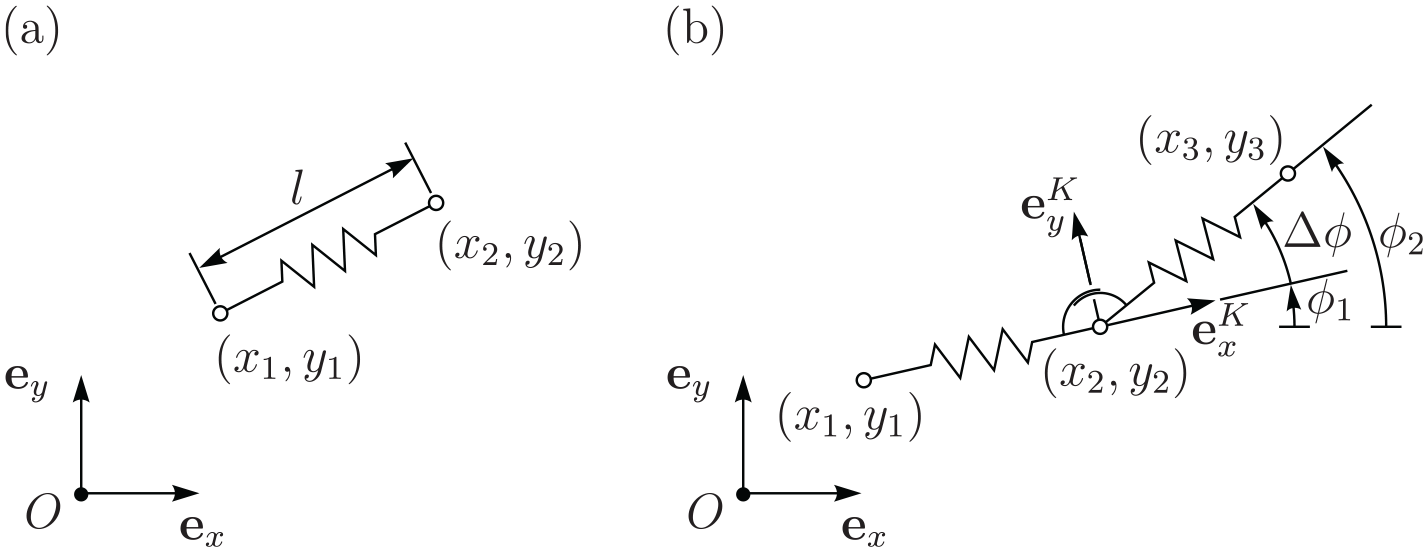
(a) Kinematics of an extensional spring and (b) kinematics of a rotational spring.
Rotational springs are interactions between three nodal points. Let

with the corresponding derivatives:
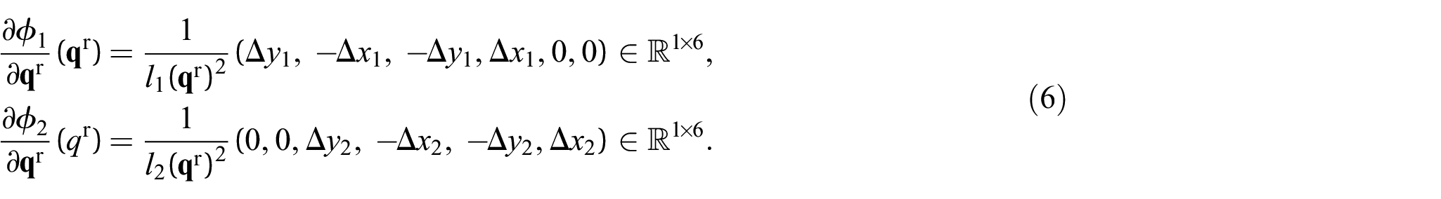
The relative angle

Straightforwardly, the derivative with respect to

Since

with

and recognizing

Again, numerically
The bi-pantographic sheet is characterized by a periodic substructure, which is captured in the discrete model by identical cells composed of extensional and rotational springs. The cells themselves do interact with each other by sharing nodal points with adjacent cells and by additional rotational springs. In the undeformed reference configuration, the cells are quadratic with width
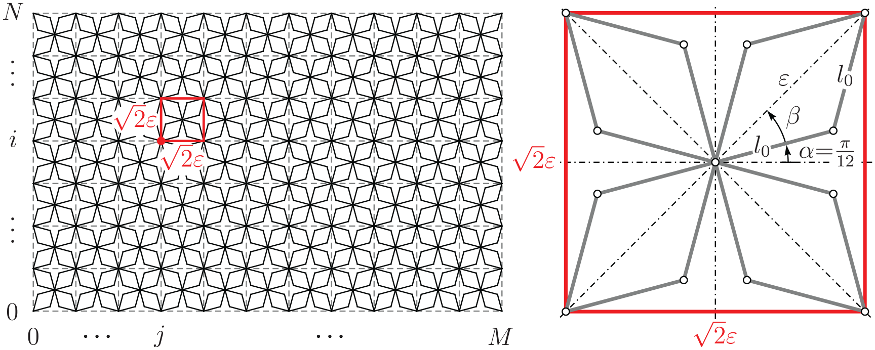
Reference configuration of the discrete model. The (i, j)th vertex and the (i, j)th cell are highlighted by a red dot and a red square, respectively. A close up shows the arrangement of the nodal points in the undeformed reference configuration.
In the deformed configuration, the Cartesian coordinates of the cell vertices are denoted

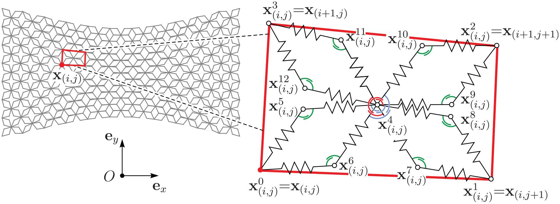
Deformed configuration of the discrete model. The (i, j)th vertex and the (i, j)th cell are highlighted by a red dot and a red quadrilateral, respectively. A close up shows the arrangement of the nodal points in the deformed configuration and their interaction by extensional and rotational springs.
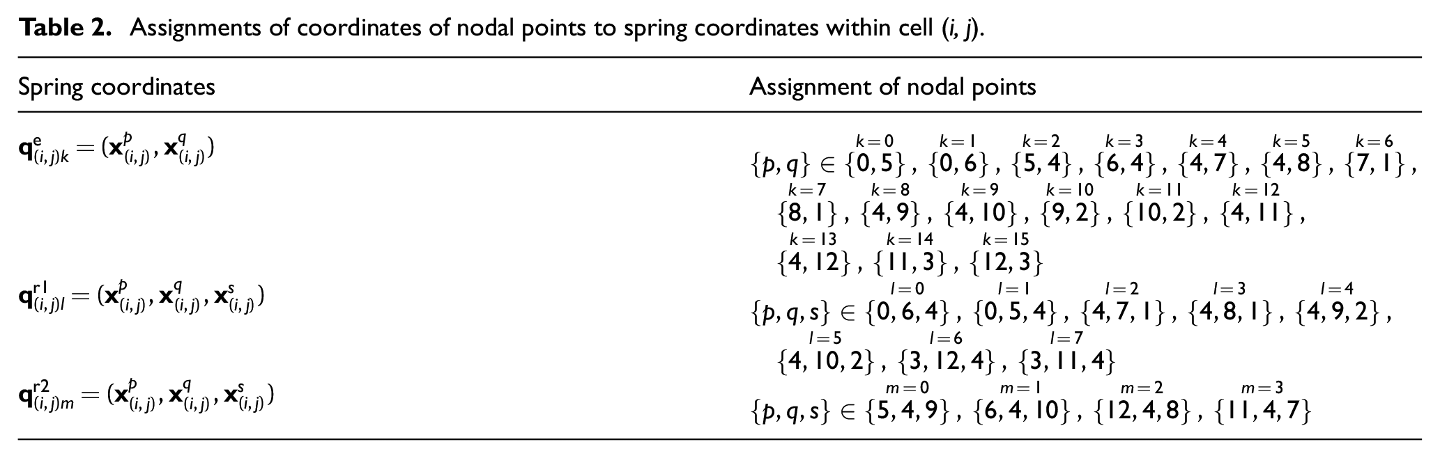
For a compact formulation of the total potential energy of the system, it is convenient to introduce spring coordinates, i.e., sets of coordinates that involve only the coordinates of the relevant nodal points for each spring. We begin with the interactions in each cell (i, j) by considering Figure 7 together with Table 2, where the explicit assignments of the nodal coordinates to the spring coordinates are specified. The axial stiffnesses of the fibers in the sheet are modeled by 16 extensional springs each with stiffness

Assignments of coordinates of nodal points to spring coordinates within cell (i, j).
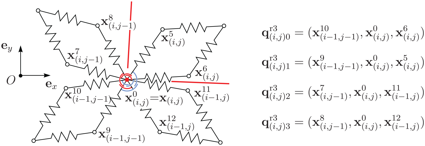
Assignments of coordinates of nodal points to spring coordinates for interaction between cells.
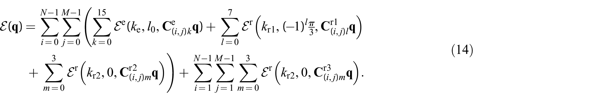
Using the spring coordinates of Table 2 and Figure 8 together with the potential energies (3) and (7), the total potential energy of the discrete bi-pantographic sheet is as follows:
Let

where
Kinematic boundary conditions are imposed by perfect bilateral constraints
The discrete system is now in static equilibrium iff the total virtual work of internal generalized forces and constraint forces vanishes for all virtual displacements, i.e.,

and the constraint equations are

which can be solved, at least locally, by a Newton–Raphson iteration scheme.
3. Experiments
This section presents the results of both, the simulation and the real world experiments. For identification of the unknown stiffness parameters, a parameter optimization procedure will be presented in the beginning. Subsequently, it is shown that the numerical model is capable for description of the pantographic sheet using a single set of experimentally optimized parameters.
3.1. Parameter optimization
The yet unknown stiffness parameters

Optimized stiffness parameters and respective relative error.
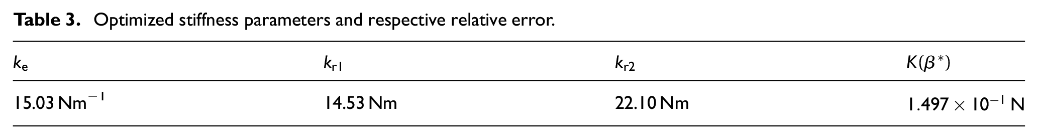
This error was minimized during an optimization procedure using all
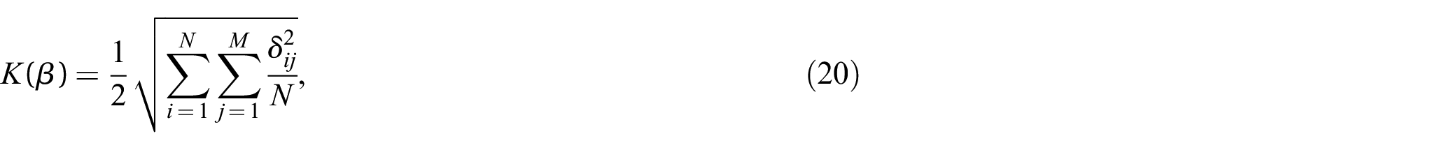
and solving the optimization problem:

using a gradient free Nelder–Mead simplex algorithm (see Gao and Han [56]). By heuristic, the initial parameters were set to
In order to study the sensitivity of the cost function a grid search was performed. For that the value of the cost function is computed for the optimal parameters
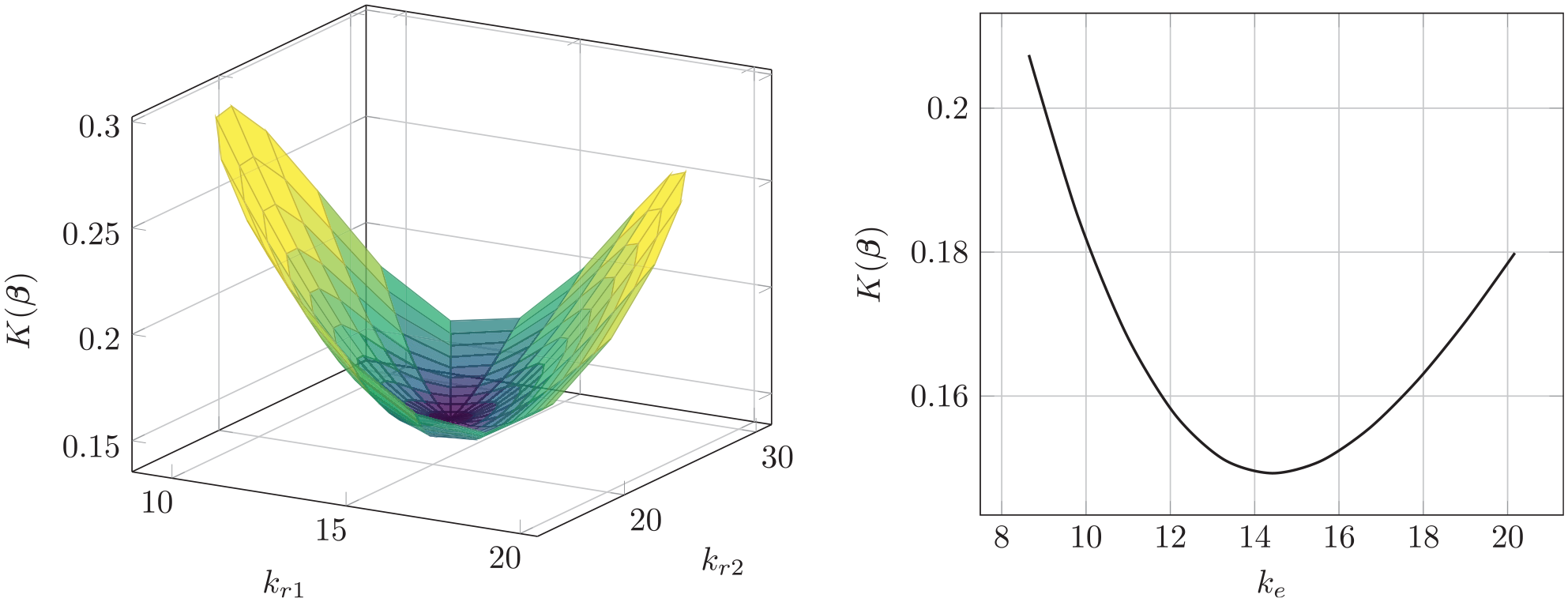
Loss surface for optimal
3.2. Experiment versus simulation
In Figure 10, the initial and deformed configurations are shown for all five experiments. It can be seen that the numerically obtained deformed configurations are in excellent agreement with the experiments, neglecting optical distortion effects introduced by the camera system. There is only a single outlier, the rectangle specimen during the extension experiment. It can be observed that during the numerical experiment, some elements of the pantographic sheet intersect each other. Obviously, this is no physical behavior and stems from the fact that self-contact and friction within the pantographic sheet is not included to the numerical model. By that, the model underestimates the required force and yields wrong displacement predictions since self-contact would prevent the torsional springs from deforming further. The force–displacement curves of the very same experiments are reported in Figure 11. Once again, for all but the first experiment, the simulated results are in excellent agreement with the experiments. This can again be explained by the missing self-contact, since the specimen is allowed to penetrating itself. If this would be prohibited by an appropriate contact formulation, the load on the extensional springs would increase and lead to higher internal forces as observed in the experiments. Furthermore, in the last two experiments, the forces are overestimated by the numerical model for very large displacements.
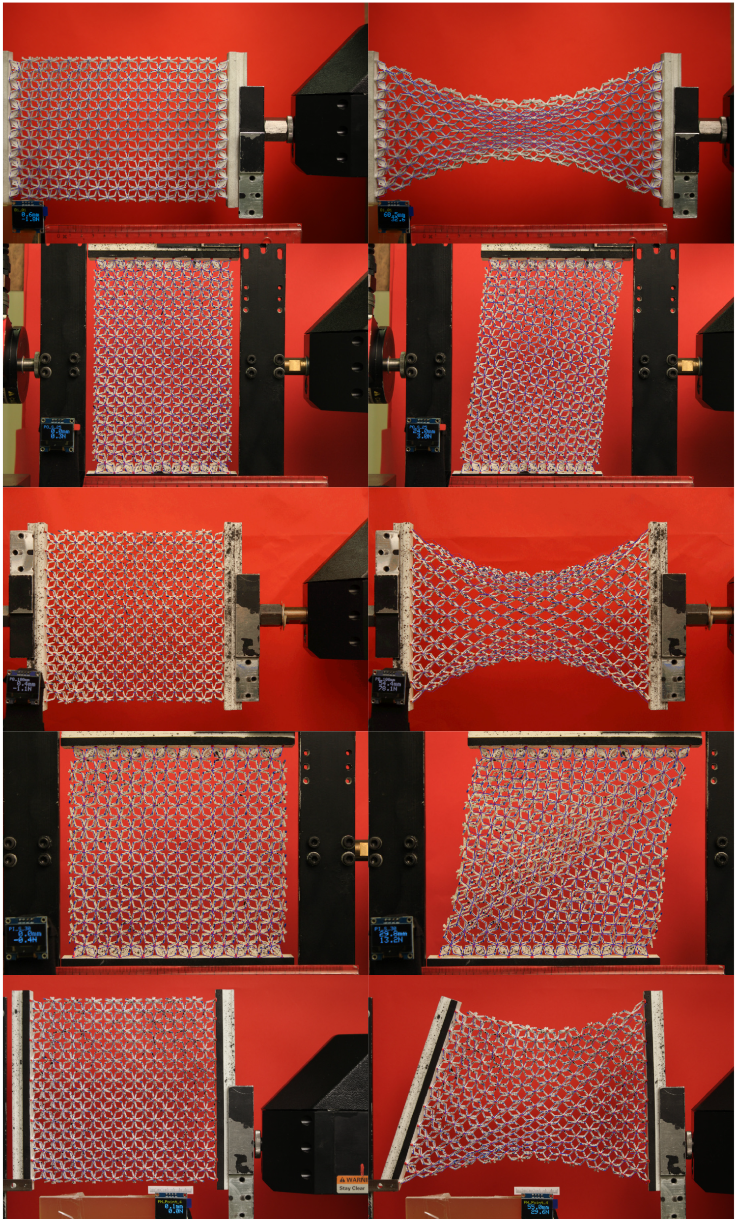
Initial and deformed configurations—simulated versus experimental results. First and second rows show, respectively, the extension and shear deformation of the rectangular specimen. Third, fourth, and sixth rows show, respectively, the extension, shear, and point deformation of the quadratic specimen. The simulated configurations are visualized by overlayed blue lines. All simulations are performed with the same parameter set given in Table 3.
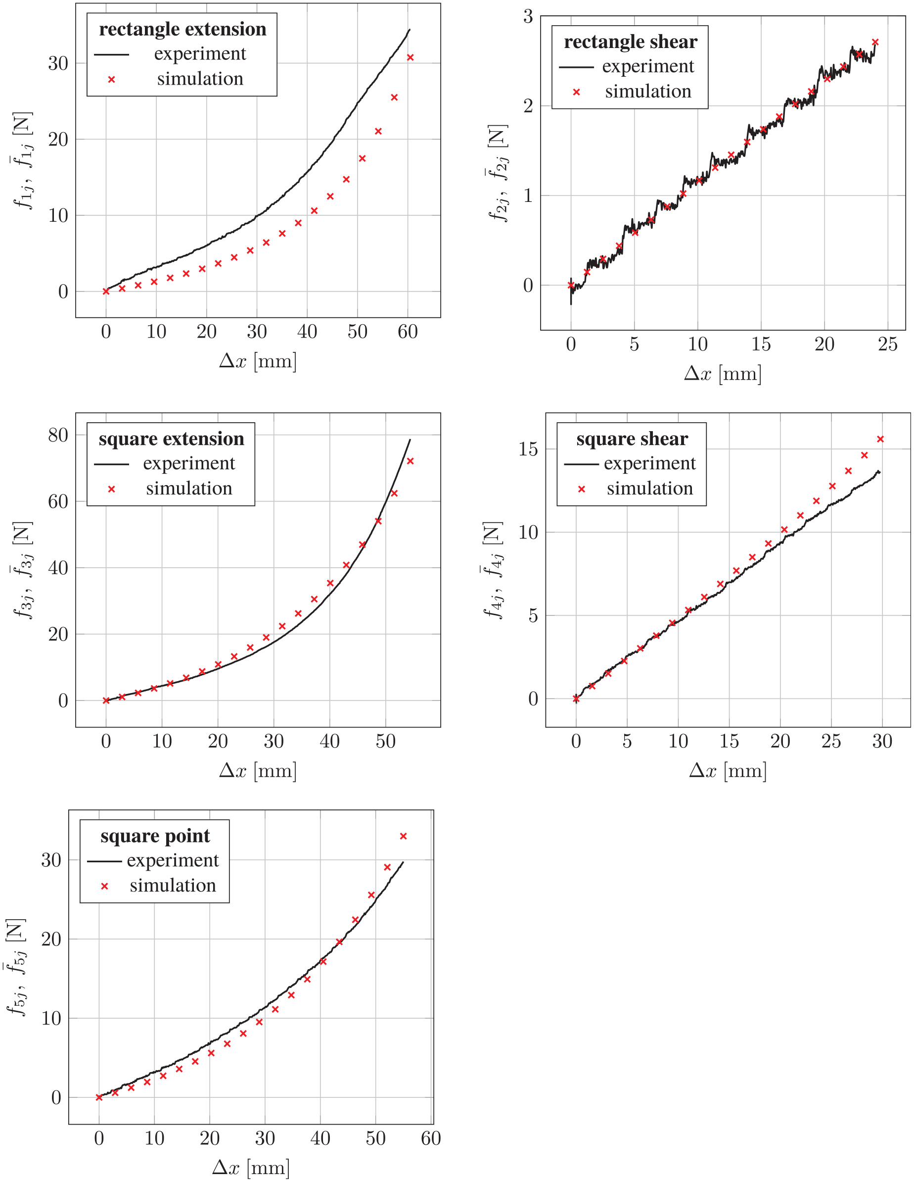
Force–displacement curves of the performed experiments. (Top left) Extension rectangular specimen (B1), (top right) shear rectangular specimen (B2), (center left) extension quadratic specimen (A1), (center right) shear quadratic specimen (B2), and (bottom left) point test quadratic specimen (B3). All simulations are performed with the same parameter set given in Table 3.
4. Discussion and outlook
Within this publication, we presented a set of five displacement-controlled experiments of pantographic sheets. They demonstrated three different kinds of deformation states, namely, extension, shear, and point loads. All applied displacements are in the regime of medium to large elastic deformations. Furthermore, a new formulation for the computation of the intermediate angle required for the torsional springs of the discrete model removed the presence of geometric singularities of the existing model [27]. The results presented in the previous section have shown that the presented discrete model is a both powerful and easy tool for description of large deformations of pantographic structures. Good predictions of the deformations and the required forces are obtained. Future investigations should clarify if the usage of nonlinear material models for the extensional and torsional springs lead to even more accurate predictions. In order to include all relevant physical effects, frictional self-contact [57,58] has to be included to the discrete model. By such an improved numerical model, the presented investigations can be extended the area of extremely large elastic deformations. Furthermore, dynamic analysis and nonlinear wave propagation of pantographic fabrics [59] can be investigated using the present model.
From the experimental point of view, optical distortion effects introduced by the camera system have to be reduced or avoided by an appropriate post-processing step. Finally, the individual nodal displacements and further derived quantities, e.g., intermediate angles, can be used for a more sophisticated optimization procedure. This requires the application of DIC (cf. [27,60]) or a full-field magnetic resonance imaging (MRI)/computed tomography (CT) scan.