We consider bifurcations from the homogeneous solution of a circular or square hyperelastic sheet that is subjected to equibiaxial stretching under either force- or displacement-controlled edge conditions. We derive the condition for axisymmetric necking and show, for the class of strain-energy functions considered, that the critical stretch for necking is greater than the critical stretch for the Treloar–Kearsley (TK) instability and less than the critical stretch for the limiting-point instability. An amplitude equation for the bifurcated necking solution is derived through a weakly nonlinear analysis and is used to show that necking initiation is generally sub-critical. Abaqus simulations are conducted to verify the bifurcation conditions and the expectation that the TK instability should occur first under force control, but when the edge displacement is controlled, the TK instability is suppressed, and it is the necking instability that will be observed. It is also demonstrated that axisymmetric necking follows a growth/propagation process typical of all such localization problems.
Necking is a phenomenon commonly observed in the tension test of ductile metals. It has also been observed in soft materials such as semi-crystalline and glassy polymers [1–6] and hydro-gels [7–9]. Numerical simulations have been conducted [10–14], and there exists a large body of literature devoted to the analysis of necking based on one-dimensional (1D) models (see, for instance, [15–27]).
Under the framework of nonlinear elasticity, the initiation condition for necking was traditionally derived as the condition for a periodic mode satisfying the end conditions to appear, in the same manner as for a buckling mode under compression (see, for instance, [28–33]). However, there also exists an alternative point of view based on the dynamical systems theory whereby localization is viewed to initiate from a “zero wavenumber” mode [34–36]. For a simple and purely algebraic demonstration of how a localized mode bifurcates from a uniform state, we refer to Fu et al. [37]. Although the critical loads associated with the two approaches are usually close to each other, the post-buckling behaviors predicted by the two approaches become qualitatively different. Whereas the “zero wavenumber” point of view predicts a post-bifurcation profile that is more and more localized away from the bifurcation point, exactly as observed in numerical simulations and experiments, the other approach predicts a periodic profile that has a vanishingly small range of validity [38]. The “zero wavenumber” approach has recently been applied to study elasto-capillary necking and has been shown to give predictions in excellent agreement with numerical simulations [39–41]. This approach has previously been applied to study localized bulging in inflated rubber tubes (see [42–44], and the references therein).
The main motivation for this study is to provide insight into necking of a dielectric membrane that is subjected to the combined action of an electric field and mechanical forces. This phenomenon has been addressed in the papers by Puglisi and Zurlo [45], Zurlo et al. [46], Fu et al. [47,48], but has otherwise received very little attention in the vast literature on electroelasticity. Instead, most literature on stability and bifurcation has focused on wrinkling [49–55] or marginal violation of the Hessian criterion [56–59].
To focus on the explanation of ideas without the extra complications arising from the incorporation of electric effect, we consider in this paper the purely mechanical case when a circular hyperelastic sheet is subjected to an all-round tension along its curved edge. The resulting trivial primary deformation is the same as in a square sheet that is subjected to equibiaxial tension. Such a square sheet is known to be susceptible to both Treloar–Kearsley (TK) and limiting-point instabilities. The former refers to the existence of deformation field in which the two in-plane stretches become unequal although the associated tensions are equal, whereas the latter refers to the fact that the tension as a function of the stretch on the trivial loading path may reach a maximum. The TK instability was first noted by Kearsley [60] based on the experimental results of Treloar [61], with its plane-strain counterpart analyzed slightly earlier by Ogden [62]. It has subsequently been studied by MacSithigh [63], Ogden [64], Chen [65], MacSithigh and Chen [66], Batra et al. [67], and Steigmann [68]. However, our focus in this study will be on a third instability, that associated with axisymmetric necking. Based on our previous studies on localized bulging of an inflated tube, it is tempting to conjecture that the bifurcation condition for necking might be that the Jacobian determinant of the two stretching forces, as functions of the two corresponding stretches, is zero on the trivial loading path (i.e., when the two in-plane stretches are equal). However, it turns out that the Jacobian determinant equal to zero may always be factorized into two separate equations, and each equation may have zero, one, or two roots for the stretch depending on the material model used. When each equation has at least one root (which is the case for the class of material models considered), the two smallest roots correspond to the TK and limiting-point instabilities, respectively. Guided by our previous studies on localized bulging of inflated rubber tubes, we postulate that localized necking may occur when a static axially symmetric extensional mode may exist in the limit of zero wavenumber (the extensional mode is the mode whose out-of-plane displacement is symmetric with respect to the mid-plane). The associated critical stretch then lies between the two smallest roots of the Jacobian determinant, and this is verified by Abaqus simulations.
The rest of this paper is organized as follows. After summarizing the governing equations in the next section, we present a linear analysis in section 3 where we derive the bifurcation conditions for the static and axially symmetric, extensional and flexural modes, respectively. Each bifurcation condition is an implicit equation relating the stretch to the wavenumber in the radial direction. As for localized bulging in inflated rubber tubes, the initiation condition for necking is postulated to be the condition for the extensional mode with zero wavenumber to exist. This condition is further discussed in relation to the TK and limiting-point instabilities. In section 4, we conduct a weakly nonlinear analysis and derive the amplitude equation in a small neighborhood of the bifurcation point and show that the necking instability is generally subcritical. In section 5, we conduct Abaqus-based numerical simulations of the TK and necking instabilities and show that for the class of constitutive models considered, TK instability appears first under force control, and it gives way to necking instability under displacement control. Section 6 is devoted to an analytical description of necking propagation. We determine the solutions for the two “phases” analytically and compare them with numerical simulations. The paper is then concluded in the final section with some additional remarks.
2. Governing equations
We consider a sufficiently large circular or square hyperelastic sheet that is subjected to an equibiaxial tension in its plane. We denote by and the undeformed and the finitely deformed configurations, respectively. The sheet thicknesses in and are denoted by H and h, respectively. We shall look for axisymmetric deformations, and so cylindrical polar coordinates will be employed, with coordinates , z, and r in corresponding to 1-, 2-, and 3-directions, respectively. The r and coordinates define positions in the plane, whereas z measures distance in the out-of-plane direction such that corresponds to the mid-plane and the surfaces to . Thus, corresponding to the equibiaxial deformation, the three principal stretches are given by
in terms of a single parameter due to the constraint of incompressibility.
To introduce the incremental equations, we denote the deformation gradient from to by and the associated nominal stress by . A small amplitude axially symmetric perturbation is now applied to , giving rise to the final configuration , and the associated incremental displacement field is given by
where and are the basis vectors in the r- and z-directions, respectively, and u and v are the associated displacement components. The deformation gradient corresponding to the deformation is denoted by F and the associated nominal stress by S. We write so that denotes the deformation gradient associated with the incremental deformation . The divergence operator with respect to coordinates in and will be denoted by Div and div, respectively.
The incremental equilibrium equation can best be expressed in terms of the incremental stress tensor defined by
where the superscript T stands for transpose, and denotes the determinant of (which is unity in the current case but is kept in the formula to maintain the generality of the formula). With the use of the identity and the equilibrium equations and , we obtain the incremental equilibrium equation
For the current axisymmetric deformation, only the equations corresponding to are not satisfied automatically, and they are given by
For our linear and weakly nonlinear analyses, we need expansions of up to the quadratic order, and they are given by
where
See, for example, Fu et al. [69]. In equation (6), the and are the Lagrangian multipliers associated with the deformations and , respectively. The are the components of given by
and and are the first- and second-order instantaneous elastic moduli, the expressions of which can be found in Ogden [70] or Fu and Ogden [69].
Due to the introduction of the extra variable , the equilibrium equations are augmented by the incompressibility condition which can be expanded as
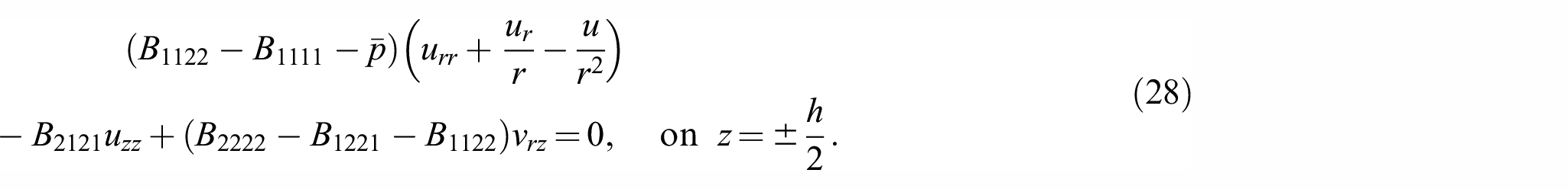
For the current problem, both the top and bottom surfaces are traction-free. Thus, the associated incremental boundary conditions are
3. Linear analysis
With linearization, the incompressibility condition (9) for the current problem reduces to
It is then convenient to satisfy this condition automatically by introducing a “stream function” such that
where as in equation (8), a subscript signifies differentiation (e.g., ). The non-zero stress components are given by
On substituting these expressions together with equation (12) into the linearized forms of equation (5) and then eliminating by cross-differentiation, we obtain
where
Note that these constants are the same as those in Dowaikh and Ogden [71], Fu and Rogerson [72] for plane-strain deformations. The , for instance, is given by
with and denoting the principal Cauchy stresses in the - and -directions. We make the assumption that both and are positive material constants, which is consistent with the Baker–Ericksen inequality [73].
Equation (18) admits a “normal mode” buckling solution of the form
where is a constant playing the role of wavenumber, is Bessel’s function of the first kind, and the other function is to be determined. This is similar to looking for periodic bifurcation solutions proportional to in rectangular coordinates. In fact, is oscillatory, although it also decays like for large values of x due to geometric spreading.
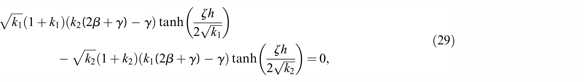
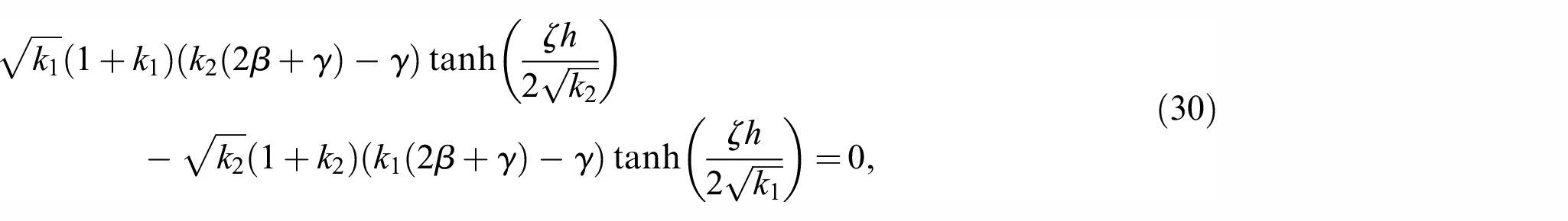
On substituting equations (21) and (24) into the four boundary conditions (26) and (28), we obtain four algebraic equations. By simple addition and subtraction, the four equations can be decoupled into two equations for and and another two equations for and . Since the determinants of the two coefficient matrices cannot vanish simultaneously, when the equations for and have non-trivial solutions, and must vanish. In this case, , and hence the vertical displacement v, are odd functions of z. The associated modes are thus extensional. However, when the equations for and have non-trivial solutions, and must vanish, and the associated modes are flexural. The bifurcation conditions for extensional and flexural modes are thus given by
respectively. Expanding equation (29) to order , we obtain
From the discussion in Fu [36], we may postulate that the bifurcation condition for localized necking can be obtained by setting the leading order term in equation (31) to zero, that is since , or equivalently
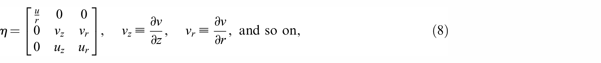
In terms of the strain-energy function , this bifurcation condition takes the form
where , , and so on, and a superscript “(0)” signifies evaluation at .
This bifurcation condition has the following interpretations. The nominal stresses in the - and -directions (i.e., r- and z-directions) are given by
On eliminating using the condition , we obtain
where in the last term, we are viewing W as a function of and . Viewing as a function of and , we obtain
On evaluation at , we obtain
Since indexes 1 and 3 can be exchanged, this may be replaced by
It is seen that setting gives the bifurcation condition (32).
In the case of localized bulging of an inflated rubber tube, the bifurcation condition was shown to be equivalent to the Jacobian determinant of the internal pressure P and resultant axial force N equal to zero when P and N are each viewed as functions of two deformation variables such as the internal volume and axial stretch [42]. In the current setting, it is natural to choose the nominal stresses and as the force variables and and as the deformation variables with eliminated using the incompressibility condition . Thus, we have
The associated Jacobian determinant can be evaluated as follows
where all the partial derivatives are evaluated at (and hence indexes 1 and 3 can be exchanged). Thus, the Jacobian determinant equal to zero implies
which may be compared with the condition for necking. The two equations in equation (38) are obviously equivalent to
which are simply the conditions for the TK and limiting-point instabilities, respectively. Thus, for the current problem, the Jacobian determinant equal to zero is not the bifurcation condition for necking.
For the purpose of illustration, we consider the following class of strain-energy functions
where , are the material constants. We then have
which is positive provided both and are positive. Assuming that the latter is true, it then follows from equation (38) that necking would occur after the TK instability but before the limiting-point instability. For instance, for the case when , we have
where the three subscripts in signify association with the TK, necking, and limiting-point instabilities, respectively. However, when with which the material exhibits moderate stiffening for large values of , we have
where we have two bifurcation values for each of the three instabilities. Finally, when which will be considered further in our numerical simulations later, we have
where we have two bifurcation values for both the TK instability and necking, but no limit points exist due to the stronger stiffening behavior of the material model. To be more precise, the second bifurcation value for necking is really the value for bulging when unloading takes place. We expect, however, that the TK instability can only occur under tension control even if the bifurcation condition (38)1 is satisfied. Under displacement control, the two in-plane principal stretches are forced to be equal, and we expect that the TK instability should give way to necking if equation (33) is satisfied. These facts will indeed be confirmed by our numerical simulations to be conducted in section 5.
4. Weakly nonlinear analysis
Having determined the bifurcation condition for necking, we now denote the critical stretch by and conduct a weakly nonlinear analysis to derive an amplitude equation for the necking solution. To simplify notation, we scale r, z, and all displacement components by h, and use the same notations for the scaled quantities. As a result, we have .
We use as the control parameter in our near-critical analysis. Guided by the analysis in Fu [36], we may write
and define a far distance variable s through
where is a constant and is a small positive parameter characterizing the order of deviation of from its critical value . Note that as a result of equation (44), the moduli and must all be expanded in terms of as well, but these expansions are not written out for the sake of brevity. The pressure is eliminated using the identity .
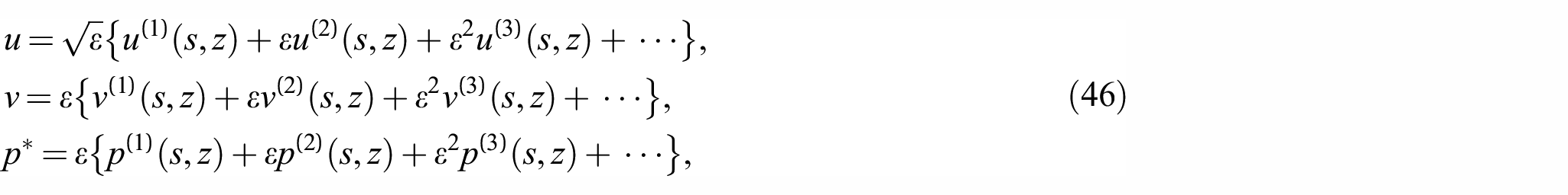
By analyzing the linear results in section 3 in the limit , we may deduce that . From the fact that the in equation (44) must appear at the order where a solvability condition should be imposed, we find that u must be of order . Thus, we look for an asymptotic solution of the form
where all the functions on the right-hand sides are to be determined from successive approximations.
On substituting equation (46) into the equilibrium equations (5), the incompressibility condition (9), the boundary conditions (10), and then equating the coefficients of like powers of , we obtain a hierarchy of boundary value problems. The solutions at different orders are obtained as follows. In the following description, the two equilibrium equations in equation (5) are referred to as the r- and z-equilibrium equations, respectively.
At leading order, the r-equilibrium equation subject to the second boundary condition in equation (10) yields
where is to be determined. Integrating the incompressibility condition then gives
where is another function to be determined. Integrating the z-equilibrium equation subject to the first boundary condition at yields the following expression for
where here and hereafter in this section all the moduli are evaluated at .
At second order, solving the r-equilibrium equation yields an expression for that contains two new functions and in the form . Subtracting and adding the second boundary condition at , respectively, we obtain
and
The first result (50) may be shown to be equivalent to the bifurcation condition (33). Integrating the incompressibility condition at second order gives an expression for that contains a new function , whereas integrating the z-equilibrium yields an expression for containing a new function . Finally, subtracting and adding the second boundary condition at , respectively, we obtain , and an expression for E(s). Solving the equation for , we obtain . Since should be bounded at , and without loss of generality, we may also impose the condition , we must set . Thus, we may set . This then completes the solution at second order.
At third order, the nonlinear terms come into play and a solvability condition must be imposed. The r-equilibrium equation can be solved to find an expression for that contains two new functions and in the form . Subtracting and adding the second boundary condition evaluated at , respectively, we obtain the amplitude equation for and an expression for . After some simplification, it is found that the amplitude equation takes the form
where a prime signifies differentiation, is defined by
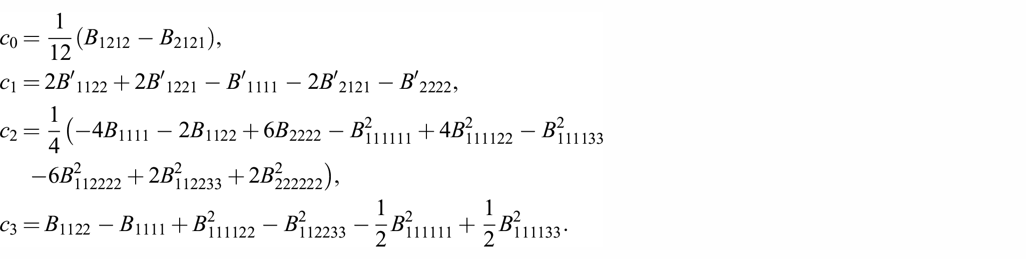
and the three coefficients are given by
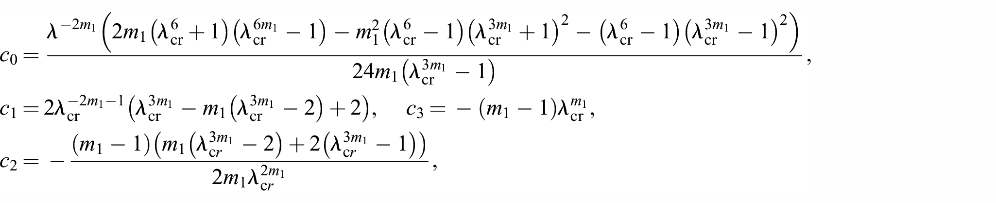
In the above expressions, denotes and so on, and we have used the bifurcation condition (50) to eliminate . When the strain-energy function is given by equation (40) with , these constants take the form
where . More specifically when , we have
As a consistency check, we may neglect the nonlinear terms in equation (52) to obtain
On substituting a solution of the form into equation (53) and the resulting expression into equation (54) and simplifying, where k is a constant, we obtain
However, expanding equation (31) around and taking , we obtain
where the subscripts “cr” signify evaluation at . We have verified that equation (55) is indeed consistent with equation (56).
As another consistency check, we may expand equation (53) fully out and omit all the terms that are divided by powers of s to obtain its planar counterpart
where
Equation (57) applies to a finitely deformed sheet that is subjected to plane-strain incremental deformations, and recovers the static counterpart of the amplitude equation (4.41) in Fu [36]. It has an exact solution given by
This solution has the property as and is the localized necking solution in the two-dimensional (2D) case.
Although the solution equation (59) for the plane-strain case tends to a constant as , we expect its counterpart for the axisymmetric case to decay algebraically due to geometrical spreading. Thus, for large s, we may neglect the quadratic part in equation (52) to obtain
where . Integrating once and setting the constant to zero, we obtain
This is a modified Bessel’s equation. It has a decaying solution given by
where is the modified Bessel function of the second kind and is a constant. On substituting equation (61) into equation (53) and integrating, we obtain
where and are the constants, and is the modified Bessel function of the second kind that has the asymptotic behavior
The asymptotic behavior (62) is consistent with our earlier assumption that decays algebraically. In principle, the fourth-order differential equation (52) can be integrated subject to the conditions
and
The necessary numerical integration will not be carried out here. Instead, we shall proceed to a fully nonlinear numerical simulation of the necking solution in the next section. We conclude this section by observing that the decay behavior (62) requires to be real. For all the material models considered, it is found that . Thus, bifurcation into a localized necking solution is generally subcritical (i.e., ).
5. Fully nonlinear numerical simulations
To verify the various theoretical predictions presented in the previous sections, we now conduct nonlinear finite element (FE) simulations within Abaqus 2020/Standard [74] to investigate the effect of loading methods and material properties on the type of bifurcation and post-bifurcation behavior. In particular, we shall verify that when the loading is force controlled, TK instability will precede necking, whereas when the loading is displacement-controlled, TK instability will be suppressed and it is necking that will occur.
5.1. Equibiaxial stretching of a square plate
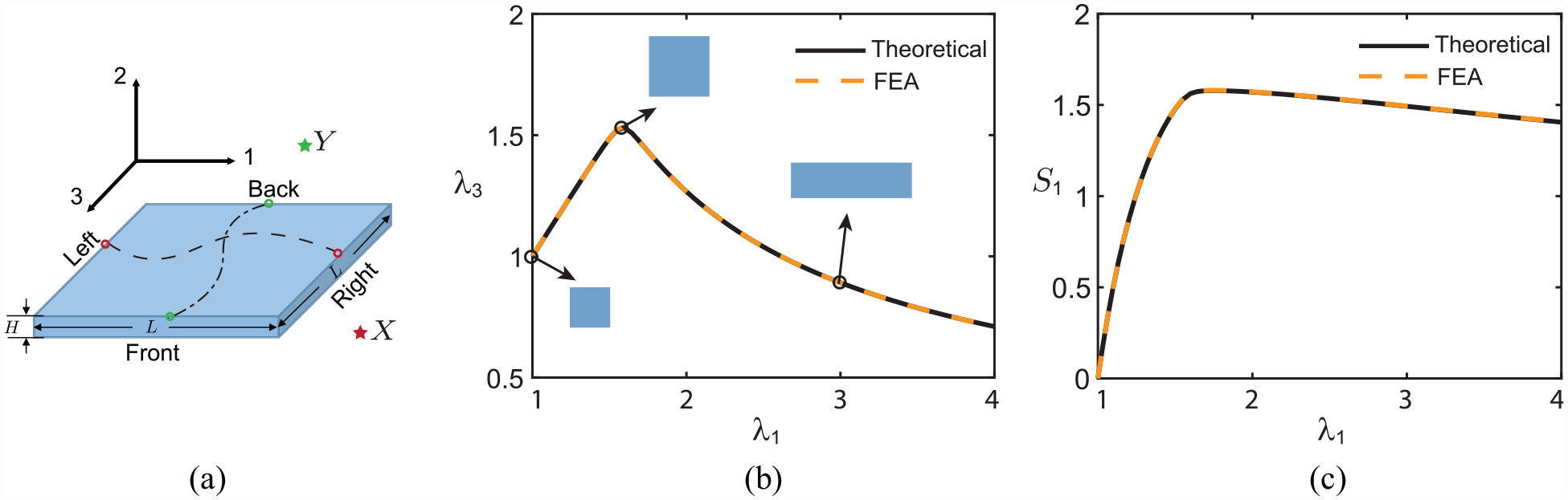
We first perform fully three-dimensional (3D) FE simulations for a square plate with , where L is the length and width of the plate and H is the thickness of the plate (Figure 1(a)). The plate is meshed using eight-node fully integrated hybrid linear brick elements (Abaqus Element C3D8H). The following constraints are imposed on the opposite faces of the plate
where N is the number of nodes on each of the four faces (with L, R, F, and B denoting left, right, front, and back faces, respectively), and denotes the displacement in the at the ith node of the left face and so on. The and denote the displacements in the at two arbitrarily chosen reference points X and Y that are used to apply the loading. In the above notations, the paired nodes and have the same coordinates in the 2–3 plane, whereas and have the same coordinates in the 1–2 plane. Moreover, to prevent rigid body motions, we fix the node at the center of the plate.
Comparison between numerical results and theoretical predictions for the Treloar–Kearsley instability. (a) Geometrical parameters and boundary conditions for the square plate. (b) versus . (c) Nominal stress scaled by versus .
The plate is loaded by applying the following concentrated forces and displacement constraints at the two reference points
where and are the concentrated forces applied at the reference points X and Y in the 1- and 3-directions, respectively, and represents the magnitude of the concentrated force. The factor 1.001 in can be viewed as an imperfection that will trigger the TK instability. Note that the near equibiaxial conditions can also be obtained by applying near equal pressures directly at the edges of the plate, but this will result in convergent issues in simulations. The imposed constraints (66) serve to circumvent convergent issues and ensure a homogeneous deformation.
It is known that the bifurcation associated with the TK instability can be either sub-critical or super-critical depending on the strain-energy function used. The corresponding test has been given by Ogden [64] in his equation (3.13). We thus consider two representative material models exhibiting these different behaviors. The first model is given by equation (40) with , and for which the bifurcation is sub-critical. We employ the modified RIKS algorithm [75] to capture the unloading behavior associated with the sub-critical bifurcation. We find that, initially, the common principal stretch in the 1- and 3-directions increases uniformly as the load increases. Then, when reaches the critical value 1.58 given by equation (42), bifurcation occurs, resulting in unequal stretches and decline of the nominal stress in both directions. As Figure 1(b) and (c) shows, there is very good agreement with the theoretical predictions for both the stretches and nominal stress.
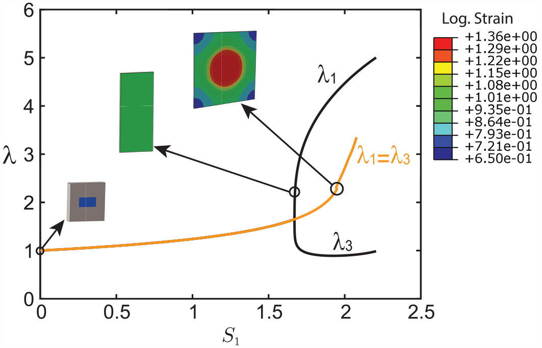
The second material model that we consider is given by equation (40) with , , and . The two limits of are such that if , the bifurcation will be sub-critical, whereas if the upper limit is exceeded, TK instability can no longer occur. The second term in equation (40) introduces straining-stiffening effect, and as a result, there are two bifurcation stretches associated with the TK instability. It is observed that the nonuniform stretches in the 1- and 3-directions initiating from the first bifurcation stretch would become uniform again at the second bifurcation stretch. This is demonstrated in Figure 2 where we compare the numerical and theoretical results for the principal stretch as a function of when . Again, we have excellent agreement between numerical results and theoretical predictions.
Emergence and disappearance of the Treloar–Kearsley instability for the material model (40) with , .
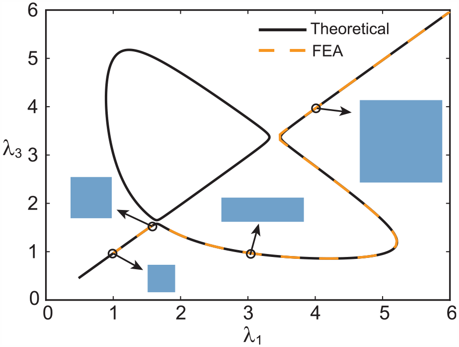
Moreover, we remark that the TK instability can also be observed in an equibiaxially stretched square plate by introducing material imperfections. To demonstrate this, we introduce a small imperfection at the center of the plate by assuming that the shear modulus in a small rectangular area is 0.5% smaller than that for the surrounding material (see the schematic in Figure 3, where the blue region in the square plate has the modulus reduced). Then, by applying equal concentrated forces at the reference points X and Y, we can observe unequal stretches when the applied nominal stress is larger than 1.67 (see the solid black lines in Figure 3, which are obtained by RIKS simulation in Abaqus). However, if the reference points are stretched using displacement control (i.e., by applying equal displacements in both directions), TK instability will be suppressed, and instead, localized necking will appear at a larger stretch as indicated by the solid yellow line in Figure 3, which is obtained using STATIC simulation in Abaqus. The TK instability giving way to necking under displacement control will be discussed further in the next section. In addition, we note that a rectangular (anisometric) imperfection is essential for observing the TK instability in a square plate. If a square (isometric) defect was introduced instead, the TK instability would not be triggered even with force control.
Numerical simulations of a square plate with material imperfections, modeled by the strain-energy function (40) with , , and . Solid yellow line: results obtained by applying equal displacements at the reference points using the STATIC module in Abaqus (in which case TK instability is suppressed and necking takes place at the kinked point in the black circle). Solid black line: results obtained by applying equal concentrated forces (force control) at the reference points using the RIKS module in Abaqus (in which case the TK instability occurs as a super-critical bifurcation).
5.2. All-round stretching of a circular plate
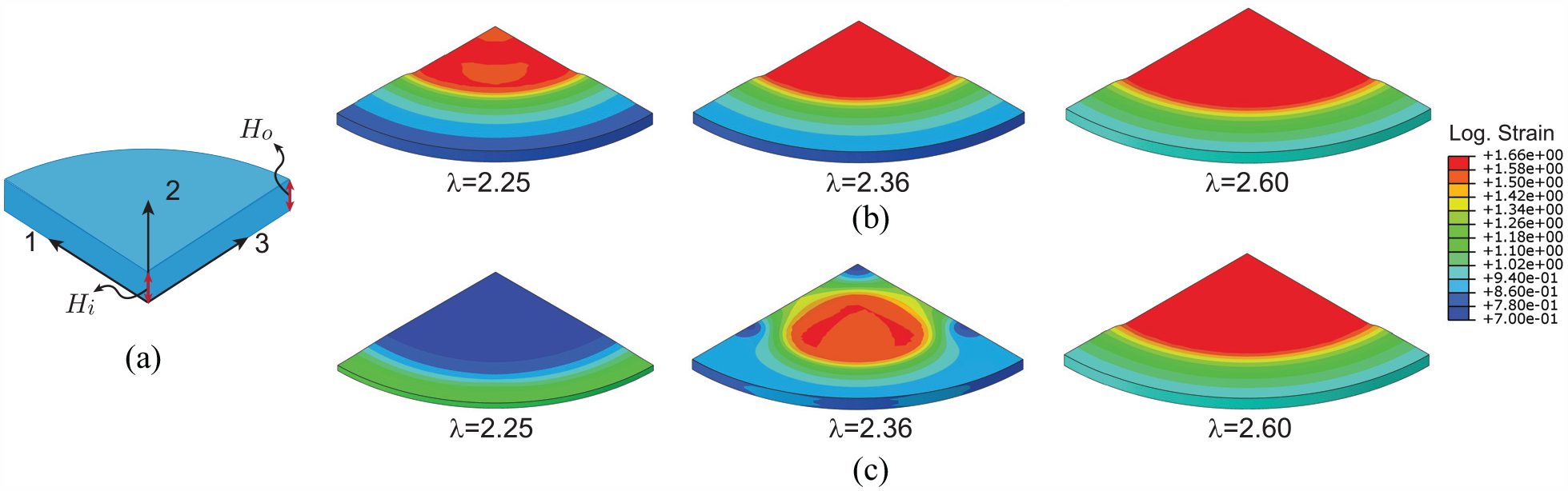
To demonstrate the occurrence of necking in a more convenient way than in the above square plate setting, we now consider a circular plate with , where and H are respectively the radius and thickness of the plate in the undeformed configuration. We control the amount of stretch on the circular edge of the plate in order to suppress the occurrence of TK instability. In addition, since strain-stiffening is essential for observing the stable propagation stage of necking, we shall consider the two-terms material model (40) with . To reduce the cost of simulations, we only model a quarter of the plate and apply axisymmetric boundary conditions on the symmetric surfaces shown in Figure 4(a). Moreover, we note that the initiation location of necking is sensitive to geometric imperfections. In Figure 4(b) and (c), we showcase snapshots of our simulations with gradual thickness thinning toward the origin or the circular edge , respectively, where and denote the plate thicknesses at the center and outer edge. For the case with thinning toward the origin, necking initiates at the center of the plate and propagates outwards as the applied load increases (Figure 4(b)). In contrast, when thinning toward the outer edge is introduced, necking initiates at the outer edge and spreads toward the center as the applied load increases. At some stage, however, the necked region switches to the center of the plate and propagates outwards with increased load (Figure 4(c)). Thus, necking starting at the center seems to be the dominant deformation mode, and so from now on, we only consider plates with thinning toward the origin. In addition, the critical stretch for necking initiation is sensitive to the magnitude of geometric imperfections. For consistence, all the following numerical results correspond to the same geometric imperfection mentioned above. Due to the presence of near-critical snap-through behavior, we also add volume-proportional damping to the model to facilitate convergence (using the option STABILIZE in Abaqus), and set the dissipated energy fraction equal to and the maximum ratio of stabilization to strain energy equal to 0.01. Furthermore, we observe that although 2D axisymmetric simulations in Abaqus considering only a rectangular slice can reduce the cost of simulations significantly, the 2D model does not seem to be capable of characterizing the necking phenomenon in the sense that axisymmetric elements are prone to distortion when necking occurs, especially for materials with only a moderate strain-stiffening behavior.
Simulations of necking in a circular plate subject to an all-round stretch, modeled by the strain-energy function (40) with , , and . (a) Geometric parameters for a quarter of the plate. (b and c) Numerical snapshots of the plate subjected to increased stretches with gradual thickness thinning toward the center (b) or the edge (c).
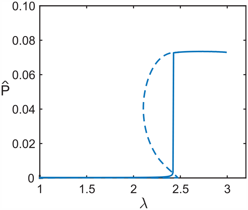
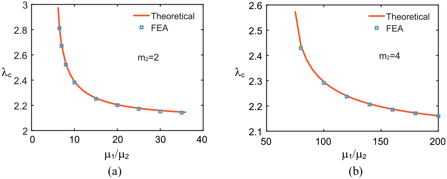
Figure 5 shows a typical plot of the necking amplitude against the stretch , where denotes the absolute difference between the vertical displacements at points and normalized by . It is seen that it is appropriate to take the numerical value of critical stretch as the stretch at which an amplitude jump takes place (the snap-through behavior mentioned above). We observe, however, that the variation of amplitude against stretch should have a slight snap-back (indicated by the dashed line) that is not captured by our simulations because the snap-back section corresponds to an unstable solution (see Figure 3(b) in Fu and Xie [76] for a discussion of the same phenomenon in the context of inflation of a membrane tube). To verify our theoretical predictions, we fix , and compare the numerical and theoretical results in Figure 6 for the critical stretch as a function of for two typical values of . It is seen that for each given , the critical stretch is a monotonically decreasing function of the ratio , and the excellent agreement between the numerical and theoretical results confirms that the bifurcation condition for necking is indeed given by equation (32), not by the criterion based on the Jacobian determinant.
Dependence of the necking amplitude on the applied stretch . The solid curve represents numerical results for the amplitude evolution at the center of the plate. The dashed line is a sketch of how the actual solution should look like. The material is modeled by the strain-energy function (40) with , and .
Dependence of the critical stretch on with (a) and or (b) and .
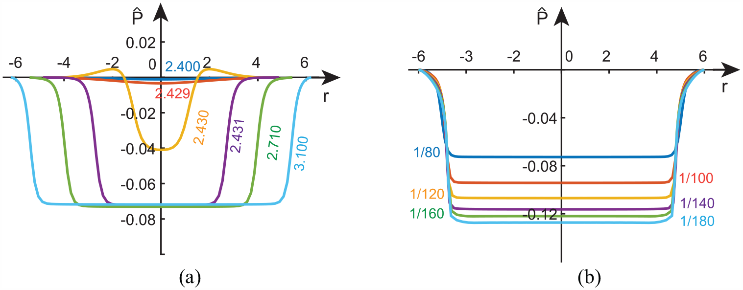
Furthermore, to quantify the post-bifurcation behavior of the necking deformation, we report evolution of the necking amplitude in Figure 7. The results shown in Figure 7(a) represent a plate with , , , and the six profiles correspond to , 2.429, 2.430, 2.431, 2.710, and 3.10, respectively (the critical stretch being 2.439). The first two profiles correspond to tiny inhomogeneous deformations due to thickness thinning, whereas the third profile with corresponds to the profile immediately after the jump in Figure 5 has taken place. Thus, the critical stretch found numerically is 2.430 which differs from the exact critical stretch 2.439 given by equation (43)2 with a relative error less than 0.4%. It is observed that the necking amplitude first increases rapidly with respect to , and then as a maximum amplitude is approached, the necked section begins to propagate outwards. This is reminiscent of the well-known growth/propagation behavior of localized bulges in an inflated rubber tube [44,77]. To demonstrate the effect of strain-stiffening on the necking amplitude, we report in Figure 7(b) the dependence on of the necking amplitude with , , and a fixed stretch of . It can be seen that the necking amplitude increases as the value of decreases, which implies that the necking amplitude is significantly affected by the strain-stiffening response of the material.
(a) Evolution of the necking profile with , , and . The six profiles correspond to , and 3.10, respectively. (b) Evolution of the necking amplitude of the plate with , and when subjected to equal-biaxial stretch of . The six curves represent , and , respectively.
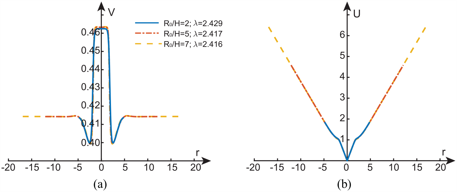
Finally, we remark that although the radius/thickness ratio used in our simulations is only 2 initially (), this ratio has become as large as 7.62 when the stretch reaches its critical value 2.439. We have run simulations to verify that this choice of initial aspect ratio is sufficient for obtaining results that are almost free of edge effects. To demonstrate this, we have shown in Figure 8 two representative simulations corresponding to superimposed on the results for . Since is the deformed radius divided by the undeformed radius, and is no longer a true characterization of local radial stretch after necking has taken place, we choose the three stretches shown in Figure 8(a) such that the maxima of V are the same (or closest numerically) and check whether the remaining profiles would then also coincide. It is seen that this is indeed the case for both V and U although the three profiles for each displacement terminate at different values of r. Notably, to demonstrate the negligible effect of radius/thickness ratio on the observed necking phenomenon with various imperfections, the results shown in Figure 8 correspond to a circular material imperfection whereby the shear modulus of the material within is 0.01% smaller than that of the surrounding material.
Total displacement (i.e., displacement measured from the undeformed configuration) in the (a) z-direction and (b) radial direction, at the lower surface of the plate as a function of the radial coordinate r in the current configuration.
6. Characterization of necking propagation
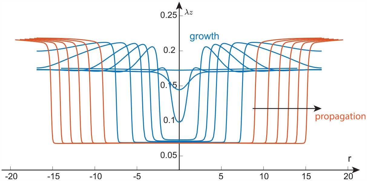
To offer more insight into the propagation stage, we have shown in Figure 9 a typical set of simulation results for the evolution of versus r as the outer radius is increased. It is seen that in the propagation stage (red curves), the is a constant in the necked region, but seems to be slowly varying in the r-direction in the un-necked region. For easy reference, we refer to the necked region centered around the origin as the “− phase” and the other region with larger thickness as the “+ phase.” In this section, we give the two “phases” an analytical description by assuming that is a constant in both “phases.” Although the two “phases” are connected by a thin transition region, we further assume that the transition region has zero thickness and simply refer to it as the interface. We use superscripts “+” and “−” to signify evaluations at the “+ phase” and “− phase” sides of the interface, respectively. Thus, for instance, denotes the azimuthal stretch as the interface is approached from the “+ phase” side.
Numerical simulation of the evolution of the principal stretch in the z-direction as the radius is increased. Thestrain-energy function is given by equation (40) with , , and , and the aspect ratio is .The blue and red curves correspond to the growth and propagation stages, respectively, and the six red curves correspond to , and 2.776.
The “− phase” is homogeneous. The solution is the same as in section 3, and it is uniquely determined by a single parameter which we take to be the stretch in the z-direction. We then have and .
For the “+ phase,” the solution is inhomogeneous although is assumed to be a constant. In terms of cylindrical polar coordinates, the axisymmetric solution is given by
The corresponding deformation gradient is given by
so that , , and . To simplify notation, from now on we shall write simply as .
By integrating the incompressibility condition det , we obtain
where C is a constant of integration. This constant may be determined by evaluating this expression at the edge of the plate
where denotes the azimuthal stretch at (so that with denoting the deformed radius). Once the hydrostatic pressure has been eliminated with the use of , the principal Cauchy stresses and are given by
It then follows that
where and is the reduced strain-energy function defined by
The only equilibrium equation that is not satisfied automatically is
With use of the result (72) and the relation , we may convert equation (74) to the form [78]
On integrating this equation across the entire “+ phase,” we obtain
where the superscript “*” signifies evaluation at the outer edge .
The jump conditions that need to be imposed across the interface are
The first two correspond to traction and displacement continuity, whereas the third corresponds to stationarity of the total energy with respect to perturbations of the interface position in the undeformed configuration [79–81].
These two equations can be used to find and for each specified (noting that ). The location of the interface, say, may be expressed in terms of and by solving the equation , i.e.
Since we must have , the must satisfy
In Figure 10, we have shown the dependence of and on , as predicted by equation (78), when the strain-energy function is given by equation (40) with , , and . On the same figure are shown six representative numerical simulation results (evaluated approximately at the center of the “+ phase”). It is seen that there is excellent agreement for the values of with relative error less than 0.57%. The agreement for is less satisfactory. We attribute this to the approximations that we have used, namely, that the thickness of the transition region is neglected and the in the “+ phase” is independent of r.
Comparison of theoretical (solid lines) and numerical simulation results (squares) for and as functions of . The squares are corresponding to the six red lines in Figure 9.
7. Conclusion
For problems that have translational invariance in one spatial direction, e.g., the inflation of a homogeneous rubber tube or extension of a homogeneous plate in a state of plane strain, a rigorous analysis based on center manifold reduction can be conducted to establish the existence of a localized solution bifurcating from the trivial state [34,35,82]. A necessary condition for localization has the simple interpretation that a static extensional mode can exist in the small wavenumber limit. For the problem of localized bulging in an inflated rubber tube, this condition has been found to be equivalent to the Jacobian determinant of two force functions equal to zero. For problems defined over an infinite or semi-infinite domain that do not have translational invariance in the direction of localization, such as the current axially symmetric necking problem, no center manifold reductions seem to have been attempted. We postulated that localized necking is still governed by the condition that an extensional bifurcation mode exists in the small wavenumber limit. Although we have not yet been able to ground this condition on any rigorous theory, we have been able to verify this postulate with the aid of Abaqus simulations. We further showed that the bifurcation condition for necking does not correspond to the Jacobian determinant equal to zero. The latter condition can always be factorized and the two factors give the conditions for the TK instability and limiting-point instability, respectively. It is also demonstrated, first numerically and then analytically, that necking evolution follows a growth/propagation process that is typical of similar localization problems. It is hoped that the current analysis will guide future studies of elastic localizations under multiple fields such as axisymmetric necking of dielectric membranes that are subjected to both electrical and mechanical loading.
Footnotes
Authors’ note
This paper is dedicated to the memory of Professor Hui-Hui Dai.
Funding
The author(s) disclosed receipt of the following financial support for the research, authorship, and/or publication of this article: This work was supported by the National Natural Science Foundation of China (grant no. 12072224).
ORCID iD
Yibin Fu
References
1.
CarothersWHHillJW. Studies of polymerization and ring formation xv. Artificial fibers from synthetic linear condensation superpolymers. J Am Chem Soc1932; 54: 1579–1587.
2.
WhitneyWAndrewsRD. Yielding of glassy polymers: volume effects. J Polym Sci Part C1967; 16: 2981–2990.
3.
CrissmanJMZapasIJ. Creep failure and fracture of polyethylene in uniaxial extension. Polymer Eng Sci1974; 19: 99–103.
4.
ZapasIJCrissmanJM. An instability leading to failure of polyethylene in uniaxial creep. Polym Eng Sci1974; 19: 104–107.
ZhangRBaiPXLeiD, et al. Aging-dependent strain localization in amorphous glassy polymers: from necking to shear banding. Int J Solids Struct2018; 146: 203–213.
7.
NaYHTanakaYKawauchiY, et al. Necking phenomenon of double-network gels. Macromolecules2006; 39: 4641–4645.
8.
MoraSPhouTFromentalJM, et al. Capillarity driven instability of a soft solid. Phys Rev Lett2010; 105: 214301.
9.
ZhaoXH. A theory for large deformation and damage of interpenetrating polymer networks. J Mech Phys Solids2012; 60: 319–332.
10.
ChenWH. Necking of a bar. Int J Solids Struct1971; 7: 685–717.
11.
NeedlemanA. A numerical study of necking in circular cylindrical bar. J Mech Phys Solids1972; 20: 111–127.
12.
NorrisDMMoranBScudderJK, et al. A computer simulation of the tension test. J Mech Phys Solids1978; 26: 1–19.
13.
BurkeMANixWD. A numerical study of necking in the plane tension test. Int J Solids Struct1979; 15: 379–393.
14.
SillingSA. Two-dimensional effects in the necking of elastic bars. J Appl Mech1988; 55: 530–535.
15.
BarenblattGI. On the neck propagation under tension of polymeric samples. Appl Math Mech1964; 28(6): 1048–1060.
16.
AntmanSS. Qualitative theory of the ordinary differential equations of nonlinear elasticity. Mechanics Today1972; 1: 58–101.
17.
AntmanSS. Nonuniqueness of equilibrium states for bars in tension. J Math Anal Appl1973; 44: 333–349.
18.
EricksenJL. Equilibrium of bars. J Elast1975; 5: 191–201.
19.
TriantafyllidisNAifantisEC. A gradient approach to localization of deformation. I. Hyperelastic materials. J Elast1986; 16: 225–237.
20.
OwenN. Existence and stability of necking deformations for nonlinearly elastic rods. Arch Ratl Mech Anal1987; 98: 357–383.
21.
ColemanBD. Necking and drawing in polymeric fibers under tension. Arch Ratl Mech Anal1983; 83: 115–137.
22.
ColemanBDNewmanDC. On the rheology of cold drawing. I. Elastic materials. J Polymer Sci1988; 26: 1801–1822.
23.
DaiHHBiQS. On constructing the unique solution for the necking in a hyper-elastic rod. J Elast2006; 82: 215–241.
24.
DaiHHHaoYHChenZ. On constructing the analytical solutions for localizations in a slender cylinder composed of an incompressible hyperelastic material. Int J Solids Struct2008; 45: 2613–2628.
25.
DaiHHPengXC. Elliptic-spline solutions for large localizations in a circular Blatz-Ko cylinder due to geometric softening. SIAM J Appl Math2012; 72: 181–200.
26.
AudolyBHutchinsonJW. Analysis of necking based on a one-dimensional model. J Mech Phys Solids2016; 97: 68–91.
27.
LestringantCAudolyB. A one-dimensional model for elasto-capillary necking. Proc Roy Soc A2020; 476: 20200337.
28.
WesolowskiZ. Stability in some cases of tension in the light of the theory of finite strain. Arch Mech Stos1962; 14: 875–900.
29.
HutchinsonJWMilesJP. Bifurcation analysis of the onset of necking in an elastic/plastic cylinder under uniaxial tension. J Mech Phys Solids1974; 22: 61–71.
30.
HillRHutchinsonJW. Bifurcation phenomena in the plane tension test. J Mech Phys Solids1975; 23(4–5): 239–264.
31.
AntmanSSCarboneER. Shear and necking instability in nonlinear elasticity. J Elast1977; 7: 125–151.
32.
ScherzingerWTriantafyllidisN. Asymptotic analysis of stability for prismatic solids under axial loads. J Mech Phys Solids1998; 46(6): 955–1007.
33.
TriantafyllidisNScherzingerWMHuangHJ. Post-bifurcation equilibria in the plane-strain test of a hyperelastic rectangular block. Int J Solids Struct2007; 44: 3700–3719.
34.
KirchgässnerK. Wave solutions of reversible systems and applications. J Diff Eqns1982; 45: 113–127.
35.
MielkeA. Hamiltonian and Lagrangian flows on center manifolds, with applications to elliptic variational problems (Lecture Notes in Mathematics, vol. 1489). Berlin: Springer-Verlag, 1991.
36.
FuYB. Nonlinear stability analysis. In: FuYBOgdenRW (eds) Nonlinear elasticity: theory and applications. Cambridge: Cambridge University Press, 2001, pp. 345–391.
37.
FuYBPearceSPLiuKK. Post-bifurcation analysis of a thin-walled hyperelastic tube under inflation. Int J Non-linear Mech2008; 43(8): 697–706.
38.
WangMFuYB. Necking of a hyperelastic solid cylinder under axial stretching: evaluation of the infinite-length approximation. Int J Eng Sci2021; 159: 103432.
39.
XuanCBigginsJ. Plateau-Rayleigh instability in solids is a simple phase separation. Phys Rev E2017; 95(5): 053106.
40.
GiudiciABigginsJS. Ballooning, bulging and necking: an exact solution for longitudinal phase separation in elastic systems near a critical point. Phys Rev E2020; 102: 033007.
41.
FuYBJinLGorielyA. Necking, beading, and bulging in soft elastic cylinders. J Mech Phys Solids2021; 147: 104250.
42.
FuYBLiuJLFranciscoGS. Localized bulging in an inflated cylindrical tube of arbitrary thickness—the effect of bending stiffness. J Mech Phys Solids2016; 90: 45–60.
43.
YeYLiuYFuYB. Weakly nonlinear analysis of localized bulging of an inflated hyperelastic tube of arbitrary wall thickness. J Mech Phys Solids2019; 135: 103804.
44.
WangSBGuoGMZhouL, et al. An experimental study of localized bulging in inflated cylindrical tubes guided by newly emerged analytical results. J Mech Phys Solids2019; 124: 536–554.
45.
PuglisiGZurloG. Catastrophic thinning of dielectric elastomers. J Electrostat2012; 70: 312–316.
46.
ZurloGDestradeMDeTommasiD, et al. Catastrophic thinning of dielectric elastomers. Phys Rev Lett2017; 118: 078001.
47.
FuYBDorfmannLXieYX. Localized necking of a dielectric membrane. Extr Mech Lett2018; 21: 44–48.
48.
FuYBXieYXDorfmannL. A reduced model for electrodes-coated dielectric plates. Int J Non-linear Mech2018; 106: 60–69.
DorfmannLOgdenRW. Instabilities of an electroelastic plate. Int J Eng Sci2014; 77: 79–101.
51.
YangSYZhaoXHSharmaP. Revisiting the instability and bifurcation behavior of soft dielectrics. J Appl Mech2017; 84: 031008.
52.
SuYPBroderickHCChenWQ, et al. Wrinkles in soft dielectric plates. J Mech Phys Solids2018; 119: 298–318.
53.
BortotEShmuelG. Prismatic bifurcations of soft dielectric tubes. Int J Eng Sci2018; 124: 104–114.
54.
DorfmannLOgdenRW. Instabilities of soft dielectrics. Phil Trans R Soc A2019; 377: 20180077.
55.
XiaGZSuYPChenWQ. Instability of compressible soft electroactive plates. Int J Eng Sci2021; 162: 103474.
56.
ZhaoXHSuoZ. Method to analyze electromechanical stability of dielectric elastomers. Appl Phys Lett2007; 91: 061921.
57.
NorrisAN. Comment on method to analyze electromechanical stability of dielectric elastomers, Appl Phys Lett 91 (2007) 061921. Appl Phys Lett2008; 92: 026101.
58.
LuTQMaCWangTJ. Mechanics of dielectric elastomer structures: a review. Extr Mech Lett2020; 38: 100752.
59.
ChenLLYangXWangBL, et al. The interplay between symmetry-breaking and symmetry-preserving bifurcations in soft dielectric films and the emergence of giant electro-actuation. Extr Mech Lett2021; 43: 101151.
60.
KearsleyEA. Asymmetric stretching of a symmetrically loaded elastic sheet. Int J Solids Struct1986; 22: 111–119.
61.
TreloarLRG. The physics of rubber elasticity. Oxford: Clarendon Press, 1949.
62.
OgdenRW. Local and global bifurcation phenomena in plane-strain finite elasticity. Int J Solids Struct1985; 21: 121–132.
63.
MacSithighGP. Energy-minimal finite deformations of a symmetrically loaded elastic sheet. Q J Mech Appl Maths1986; 39: 111–123.
64.
OgdenRW. On the stability of asymmetric deformations of a symmetrically-tensioned elastic sheet. Int J Eng Sci1987; 25: 1305–1314.
65.
ChenYC. Stability of homogeneous deformations of an incompressible elastic body under dead-load surface tractions. J Elast1987; 17: 223–248.
66.
MacSithighGPChenYC. Bifurcation and stability of an incompressible elastic body under homogeneous dead loads with symmetry. Part I: general isotropic materials. Q J Mech Appl Maths1992; 45: 277–291.
67.
BatraRCMüllerIStrehlowP. Treloars biaxial tests and Kearsleys bifurcation in rubber sheets. Math Mech Solids2005; 10: 705–713.
68.
SteigmannDJ. A simple model of the Treloar-Kearsley instability. Math Mech Solids2007; 12: 611–622.
OgdenRW. Non-linear elastic deformations. New York: Ellis Horwood, 1984.
71.
DowaikhMAOgdenRW. On surface waves and deformations in a pre-stressed incompressible elastic solid. IMA J Appl Math1990; 44: 261–284.
72.
FuYBRogersonGA. A nonlinear analysis of instability of a pre-stressed incompressible elastic plate. Proc R Soc Lond A1994; 446: 233–254.
73.
BakerMEricksenJL. Inequalities restricting the form of stress deformation relations for isotropic elastic solids and Reiner–Rivlin fluids. J Washington Acad Sci1954; 44: 24–27.
RiksE. An incremental approach to the solution of snapping and buckling problems. Int J Solids Struct1979; 15: 529–551.
76.
FuYBXieYX. Stability of localized bulging in inflated membrane tubes under volume control. Int J Eng Sci2010; 48: 1242–1252.
77.
KyriakidesSChangYC. The initiation and propagation of a localized instability in an inflated elastic tube. Int J Solids Struct1991; 27: 1085–1111.
78.
HaughtonDMOgdenRW. Bifurcation of inflated circular cylinders of elastic material under axial loading II. Exact theory for thick-walled tubes. J Mech Phys Solids1979; 27: 489–512.
79.
GrinfeldMA. On conditions of thermodynamic equilibrium of the phases of a nonlinear elastic material. Dokl Akad Nauk SSSR1980; 251: 824–827.
80.
FreidinABChiskisAM. Phase transition zones in nonlinear elastic isotropic materials. Izv AN USSR Mekh Tverdogo Tela1994; 29: 91–109.
81.
FuYBFreidinAB. Characterization and stability of two-phase piecewise-homogeneous deformations. Proc R Soc A2004; 460: 3065–3094.
82.
HaragusMIoossG. Local bifurcations, center manifolds, and normal forms in infinite-dimensional dynamical systems. London: Springer, 2011.