
Abstract
Auxetic behavior refers to lateral widening upon stretching or, in reverse, lateral shrinking upon compression. When an initially auxetic structure is actuated by compression or extension, it will not necessarily remain auxetic for larger deformations. In this paper, we investigate the auxetic range in the deformation of a periodic framework with one degree of freedom. We use geometric criteria to identify the interval where the deformation is auxetic and validate these theoretical findings with compression experiments on sample structures with
1. Introduction
Auxetic structures have the curious property that they shrink in all directions under uniaxial compression and widen in all directions under stretching. Early considerations on this type of behavior appeared in [1–4]. Foam structures reported by Lakes [5] kindled wider interests in cellular and periodic designs which exhibit auxetic deformations [6, 7]. The scope of investigations and proposed applications can be gleaned from a string of reviews [8–15]. Advances in additive manufacturing have permitted the fabrication of increasingly complex and intricate structures [16–20], leading to a renewed emphasis on rational design. As observed in [21], “the rational design of metamaterials with a target property or functionality remains fiendishly difficult, and many designs so far have relied on luck and intuition.”
In this paper, we focus on periodic bar-and-joint frameworks with auxetic behavior. Structures of this type, also referred to as a “rods and hinges lattices,”“metamaterials of rigid bars and pivots,” or simply “trusses,” have been frequently used in investigations concerned with the geometric underpinnings of auxetic deformations [22–26]. We note, in this context, that crystalline materials provide a vast array of periodic bar-and-joint frameworks, also called “crystal structures” or “crystal nets” [27–30]. Displacive phase transitions, occurring under variations of temperature or pressure, can oftentimes be modeled as periodic framework deformations [31–33] and inquiries about auxetic behavior have been conducted for various structures [34–37].
Materials which can be modeled as periodic bar-and-joint frameworks allow a direct comparison of theoretical predictions with experimental results, thereby offering a more precise understanding of the fundamental role of geometry in functional responses. For auxetic behavior, there is a strictly mathematical theory, developed in [38–40], which gives necessary and sufficient conditions for the existence of auxetic infinitesimal deformations and leads to a comprehensive design methodology. As auxetic behavior is necessarily confined to a limited range, these results bring to the fore the problem of identifying, in the global deformation space of a periodic framework, all regions where auxetic deformations are possible [41].
In the present study, we explore the long-range behavior of a three-dimensional periodic framework with one degree of freedom, introduced in [42]. Figure 1 illustrates the sample structure produced for experiments and an actual response recorded for compression. We determine the entire deformation path of the framework and recognize auxeticity along a limited arc of this trajectory. The auxetic interval of the framework is obtained through rigorous geometric calculations. The existence of this interval is then validated through experiments on 3D printed structures with
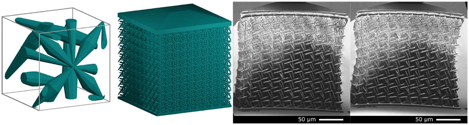
The framework used in compression experiments. Description and dimensions are given in the text. See also Figure 6.
In our concluding section, we elaborate on the significance of one-degree-of-freedom framework designs and the importance of the notion of auxetic interval, which allows a numerical comparison of auxetic performance for different frameworks in this class via the volume increase factor for the unit cells at the endpoints of the interval.
2. The periodic framework
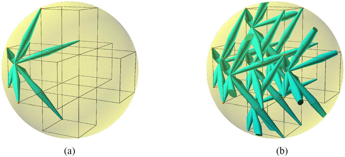
The specific periodic framework considered here belongs to a family of designs presented in [42]. It is obtained from the diagram shown in Figure 2. On the left, we see a fragment of a cubic lattice consisting of 7 cubes inside a sphere passing through the 24 outlying corners. In the middle, the image shows an octet of lattice points chosen from these corners and connected by edges to an additional vertex placed on the sphere. This common vertex of the eight edges is chosen along the axis running through the center of the sphere and the centers of the two squares determined by the octet of lattice points. This gives a rotational symmetry of order four to the generating configuration and we use the expression “four-fold symmetry” to refer to the resulting crystallographic symmetry of the periodic framework.
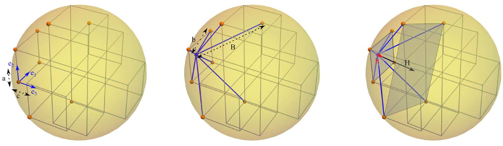
Design diagram of the periodic framework. The unit vectors
The periodicity lattice is
2.1. The global deformation space
The geometric model assumes all edges of the framework to be rigid bars and all joints to allow free relative rotation of the incident bars. The initial configuration of this periodic framework then has one degree of freedom and the deformation mechanism can be visualized and described by taking into account the preservation of the four-fold rotational symmetry. The vectors
When the framework moves along its deformation path, it suffices to describe what happens to the eight-bar configuration depicted in Figure 2. We observe that the common vertex remains along the fixed axis and the four ends of the short bars form a square of edge length
If we denote by


We note that

which implies the algebraic relation:

Considering that the Gram matrix

where
Gram matrix trajectory in
2.2. Geometrical determination of the auxetic interval
The detection of the precise interval where the deformation is auxetic will illustrate the geometric criteria established in [38, 39]. In particular, auxetic behavior requires, for all pairs of orthogonal directions, simultaneous elongation, or, under compression, simultaneous shrinking. Computationally, we have to see where

Figure 4 shows the graph of this function. We have

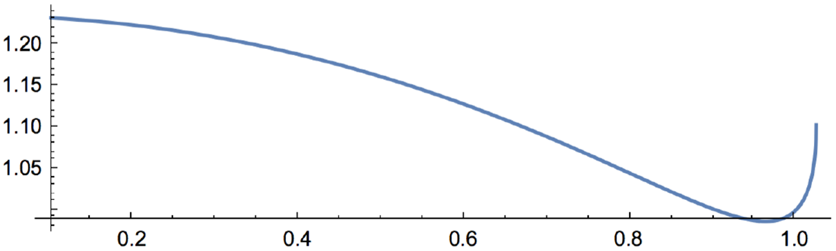
The graph of
There is one critical point in

and (7) is negative to the left and positive to the right of
The auxetic interval is where


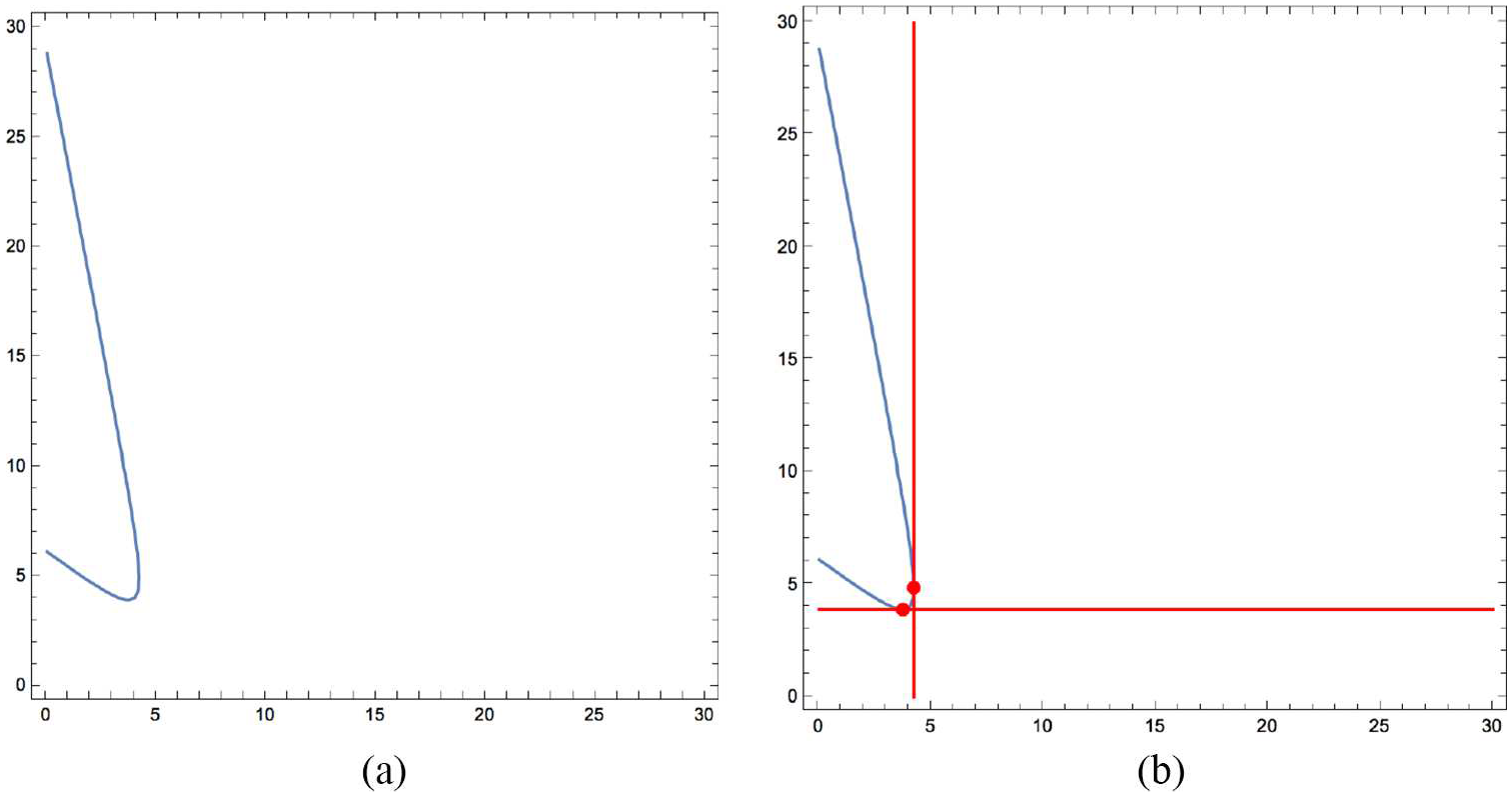
The auxetic interval can be retrieved based on the directions of the tangents to the Gram matrix trajectory given in (5) and shown in Figure 3. By [38], the auxetic locus is where the tangents have directions belonging to the positive semidefinite cone of
Thus, in Figure 3, the auxetic interval can be visualized as the arc between the points of the trajectory where the tangent is horizontal and then vertical. These points correspond to

We find

and this determines the endpoints of the auxetic interval on the Gram matrix trajectory as


Figure 3 shows the auxetic arc of the trajectory between these two endpoints. The relation
3. Experimental methods
3.1. Structure design
From the framework blueprint described previously, a monolithic design was created. The design process is illustrated in Figure 5.
The monolithic implementation of the periodic framework is developed in two steps. (a) First, the edges in the blueprint of Figure 2 are replaced by bicones. (b) Second, the eight bicones that make up a fundamental unit are copied and translated along the vectors of the periodicity lattice to generate the periodic structure.
To create a monolithic sample of the framework, each of the edges in the blueprint shown in Figure 2 is replaced by a bicone, as shown in Figure 5(a). By doing this, we obtain a fundamental unit consisting of eight bicones connected in a single point. We can then replicate this fundamental unit and translate it along the vectors of the periodicity lattice, as illustrated in Figure 5(b), to obtain the complete monolithic structure.
The monolithic structure was realized with edge lengths of
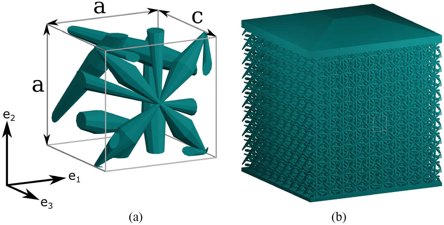
The designed periodic framework. (a) A single unit cell, with the unit cell volume outlined by gray lines. The dimensions
3.2. Sample creation
All sample structures were manufactured using two-photon lithography on a Nanoscribe Photonic Professional GT (Nanoscribe GmbH, Eggenstein-Leopoldshafen, Germany), using IP-Dip photoresin on a silicon substrate. This machine is capable of a lateral resolution of
After creating and testing the structures, it was observed that the plates on the top and bottom of the structures appear slightly curved and the central part of the structure is already slightly narrower than the top and bottom parts. This is likely an effect of the shrinkage of the used resin, which is reported to be up to 10% (see [43]). As we describe in Section 3.4, a central region of the structure is measured to decrease the effect of these boundaries.
3.3. Sample testing
Two uniaxial load cases are considered. One where a uniaxial deformation is applied along the four-fold symmetry axis, i.e., along direction
In the other load case, the structure is uniaxially deformed along direction
Three structures were constructed, one for each testing orientation. The two structures to be compressed along
The structures were compressed using a Femtotools FT-NMT03 nanomechanical testing system inside of a Jeol JSM-6010LA SEM. For the compression tests, a silicon microforce sensing probe with a tip width of
3.4. Experimental probing of the auxetic interval
Owing to the four-fold rotational symmetry described in Section 2, the auxetic interval can be determined by measuring the effects of applied deformations on the distances
Figure 7 shows a unit cell of the framework under the three different viewing directions. The distance labels
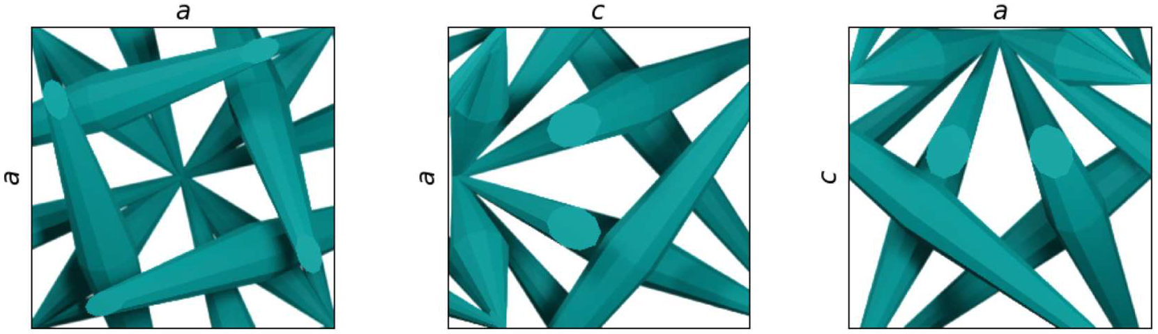
Schematics of the three distinct viewing directions of the structure that are used in this study. The images show an orthographic view of a single unit cell of structure and the relevant dimensions
We observe that, according to Figure 4, when
3.5. Data processing
The recorded images were used to obtain quantitative data on the strains in the compressed structures. First, the images were rotated and straightened to correct for perspective. To do this, four points on the structure were selected and transformed to span a square.
The images were then processed using digital image correlation. The deformations were tracked in a central region of the structure, consisting of
4. Results
Compression tests were performed on the structures for each of the three distinct viewing directions. For each test, the resulting horizontal and vertical strains were recorded. In the following figures, we report the engineering strains:

where
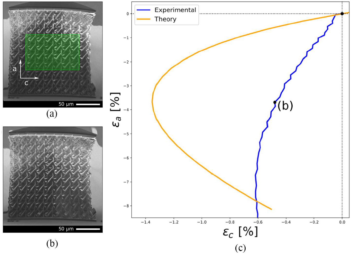
The results of the first experiment are shown in Figure 8. Here, the structure was compressed along the
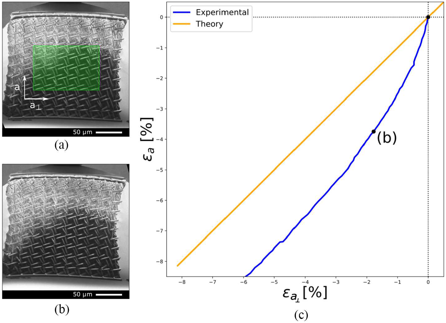
Strains and images from a compression test along the
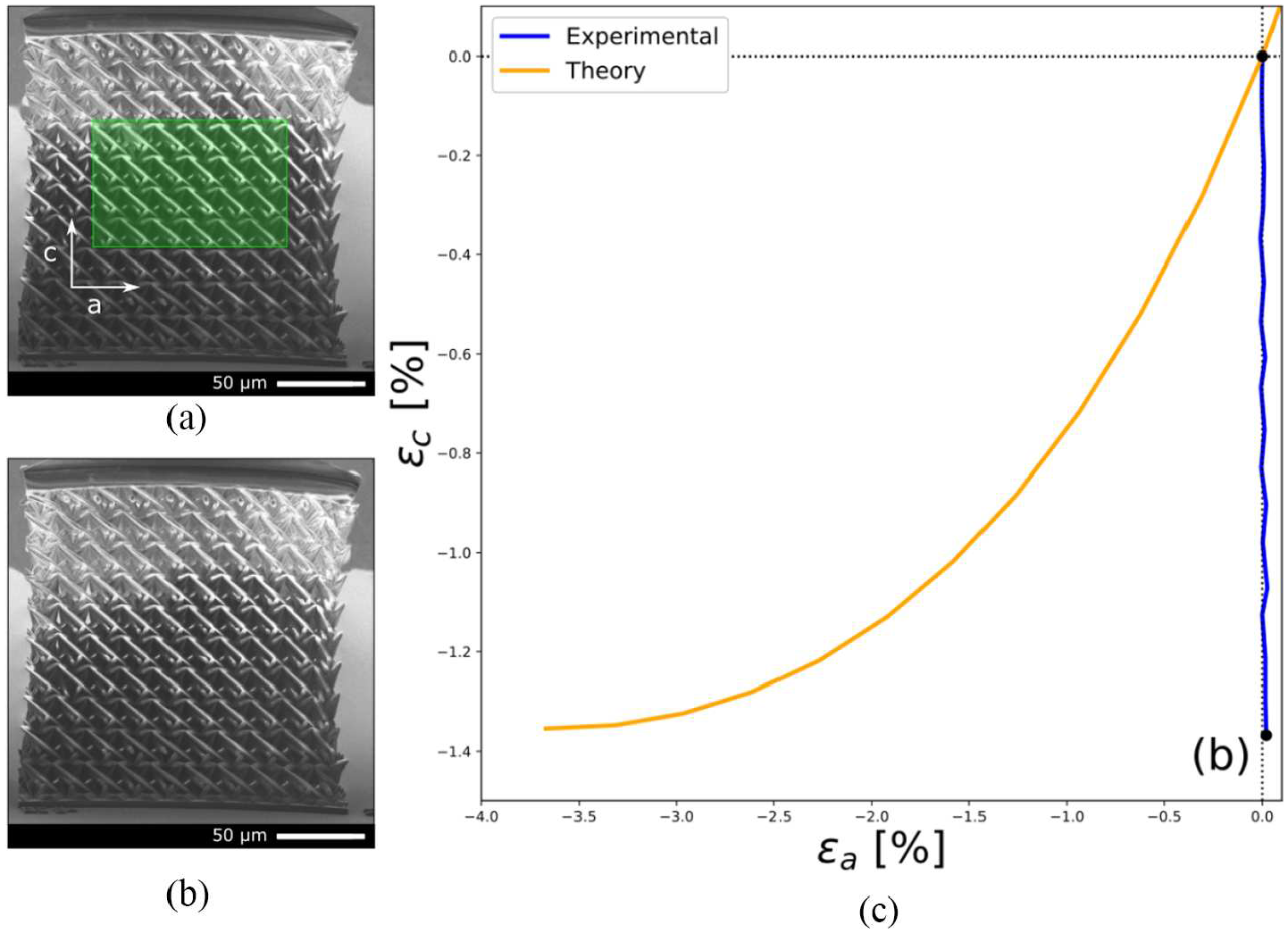
Figure 9 shows the results of the experiment where the structure was compressed along the
Strains and images from a compression test along the
Figure 10 shows the results from the final viewing direction, where the structure was compressed along the
Strains and images from a compression test along the
In the images for all three measurements, we can see that the strains in the structures are not evenly distributed. In particular, in the images of Figure 8, we see that the center of the structure contracts substantially more than the regions at the top and bottom of the structure.
5. Discussion
When the structure is compressed along the
Outside of the calculated auxetic interval, we see that the orthogonal
Overall, we observe that the nature of the deformation agrees with the geometric model. As the structure demonstrated no lateral expansion for each of the three orthogonal views of the structure, we have validated auxetic behavior over the calculated interval admitting compression.
6. Conclusion
In this study, we have shown that a framework design based on a geometric theory of periodic auxetics allows for a very explicit and precise description of its global periodic deformation. Furthermore, we have shown that such a framework can be produced using existing additive manufacturing technology at the micrometer scale. Compression tests have been performed on the manufactured frameworks and measurements confirm the auxetic behavior in the interval calculated using the theoretical model.
We emphasize the distinctive role of periodic framework designs with one degree of freedom. In the presence of several degrees of freedom, additional controls or constraints would be needed for selecting an auxetic deformation trajectory from response possibilities which definitely include non-auxetic deformations. Thus, the existence of a general methodology for one degree of freedom auxetic design is particularly relevant [40, 42]. The framework design considered here is of the simplest kind, in view of the fact that it has just two orbits of vertices under periodicity. Moreover, the presence and preservation of the four-fold symmetry allows explicit and precise computations.
Our investigation highlights the importance of predicting and recognizing the interval where auxetic behavior occurs. Within the class of one-degree-of-freedom periodic designs, the volume increase factor for the unit cell at the endpoints of the auxetic interval, provides a comparison criterion for auxetic performance.