
Abstract
In this paper, a pseudo-rigid body model is proposed for the analysis of a spatial mechanical metamaterial and its application is demonstrated. Using this model, the post-buckling behavior of the mechanical metamaterial can be determined without the need to consider the whole elastic structure, e.g., using finite-element procedures. This is done by analyzing a porous cylindrical mechanical metamaterial using a rigid body mechanism, consisting of rigid squares that are connected at their corners. Stiffness in this model comes from torsion springs placed at the connections between rigid parts. The theory of the model is presented and the results of two versions of this model are compared through experiments. One version describes the metamaterial in the free state, while the other, more extended, version includes clamped boundaries, matching the conditions of the experimental set-up. It is shown that the mechanical behavior of the spatial metamaterial is captured by the models and that the shape of the metamaterial in the deformed state can be obtained from the more extended model.
Keywords
1. Introduction
Mechanical metamaterials are artificially designed materials of which the mechanical properties are dominated by their structures, rather than by the chemical composition of the constituent materials. In this way, materials can be designed with novel properties, such as negative Poisson’s ratios, vanishing elastic moduli, and extreme stiffness to weight ratios [1, 2].
These material structures have potential applications in a variety of fields. Mechanical metamaterials with negative Poisson’s ratios are applied in a diverse range of industries [3]. In medicine, such structures have been proposed as stents [4, 5]; in sporting equipment, structures with negative Poisson’s ratios have been used in the soles of running shoes for their shock-absorbing properties [6] or in textiles for better shape-fitting to the wearer [7].
Material structures with vanishing elastic moduli could find applications in impact protection and seismic isolation [8]. Materials with extreme stiffness to weight ratios could be used in automotive or aerospace applications to reduce weight without reducing the strength of the parts fabricated from these structured materials [9, 10].
Mechanical metamaterials can be split into two classes: bending- and stretching-dominated structures [11, 12], named after the most dominant deformation of the slender parts of their structures. Stretching-dominated structures are generally designed to be stiff and light [13]. Bending-dominated structures, however, have been designed to have a broader range of properties, such as a negative Poisson’s ratio [14–16] and a number of stable states [17–20]. This paper is focused on the modeling of bending-dominated structures.
Because of the elastic deformations of the structure, bending-dominated mechanical metamaterials require extensive computational effort for analysis, since the complete elastomeric structure must be considered at once. Generally, this is achieved using finite-element methods [20–22].
As an alternative to the computationally intensive finite-element methods, pseudo-rigid body models (PRBMs) [23] can be used for the analysis of these structures. In this method, the elastomeric structure is approximated by a rigid body mechanism with torsion springs at the hinges to model the elastic forces. Using this method, the calculations for analysis become significantly simpler and analytical solutions of the material properties can be obtained. Similar methods have been used by Florijn et al. [17] to model a planar bistable mechanical metamaterial and by Turco et al. [24] to model planar pantographic lattices.
Current examples of rigid body mechanisms used to model mechanical metamaterials are either solely kinematic [25–27] or only consider planar structures [17, 28–30]. However, for spatial mechanical metamaterials, PRBMs have not yet been applied, while for these more complicated structures the resulting computational efficiency will be of significant benefit.
In this paper, we present a PRBM for the analysis of the kinematics as well as the force–displacement characteristic of a spatial mechanical metamaterial. We investigate a known spatial tubular mechanical metamaterial [31–33]. This tubular structure has a negative Poisson’s ratio, owing to a square array of round holes, which is patterned around the circumference of the cylinder. The PRBM we present in this paper is able to replicate this property, as well as capturing the force–displacement behavior of the structure.
By including fixed boundary conditions, matching the clamping in the experimental set-up in one of the models, we are able to model the inhomogeneously deformed shape of the elastomeric structure. This is an advantage over common unit-cell-based models, where the deformations of the structure are assumed to be periodic and therefore only homogeneous deformations of the metamaterial are considered [34].
We will first describe how the tubular mechanical metamaterial deforms under uniaxial compression and indicate the geometrical features that give rise to the negative Poisson’s ratio. Secondly, we present and discuss two representative spatial PRBMs for the analysis of the metamaterial, both of which share the same geometrical structure. One model describes the metamaterial under idealized conditions, while the other also considers boundary effects due to clamping. Finally, we will validate the two implemented models with experimental data.
2. The elastomeric tubular structure
The tubular mechanical metamaterial under study in this paper consists of a hollow cylinder with a square array of pores around the circumference, as shown in Figure 1. Figure 1(a) shows a front view of the structure and Figure 1(b) shows a top view. Figure 1(c) shows a section of a single pore of the structure, which is circular at the outer perimeter of the cylinder and elliptical at the inner perimeter. It was made such that the holes follow the curvature of the cylinder, with the wall thickness between the holes remaining constant throughout the radius of the cylinder.
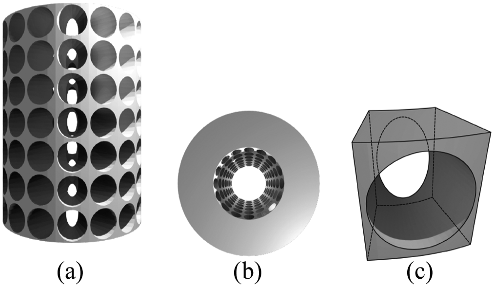
The tubular mechanical metamaterial under study in this paper. Shown are a front view (a), a top view (b), and a section containing a single hole (c). This structure has 7 holes along the height and 16 holes around the circumference. The holes are tapered such that they are round at the outer perimeter and elliptical at the inner perimeter, with a constant thickness of the most slender parts between the holes.
Figure 2 shows snapshots taken during compression of the tubular mechanical metamaterial along the cylinder’s central axis. Two distinct stages can be identified in the compression characteristics:
Pre-buckling. The whole structure undergoes a uniform vertical strain. The holes deform into ellipses, with their largest principal axis oriented horizontally, as shown in Figure 2(b).
Post-buckling. The slender parts between the holes buckle and the pattern of holes deforms into alternatingly oriented ellipses, as shown in Figure 2(c) to (f).
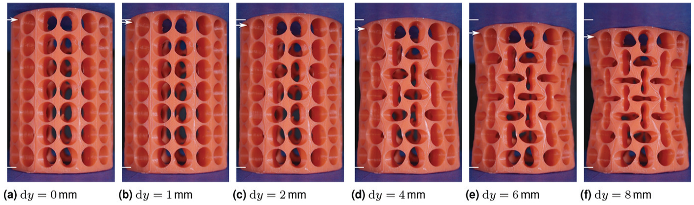
The elastomeric, porous cylinder at various stages of vertical compression
During the first stage of the compression, the slender parts between the holes undergo uniform vertical compression. The Poisson’s ratio of the structure is therefore determined by the Poisson’s ratio of the material. However, because the deformation is mostly localized in the slender parts, the overall structure has a Poisson’s ratio close to zero.
In the second stage of the deformation, the slender parts between the holes have buckled and the holes form a checkerboard pattern of horizontally and vertically elongated ellipses. This pattern transformation causes a new deformation mode, in which the structure has a negative Poisson’s ratio; the radius of the structure decreases with increasing compression along the cylinder axis. It is in this stage that the deformation of the metamaterial becomes bending-dominated.
In the post-buckling stage of the deformation, the majority of the deformation of the structure is localized in the slender parts between the holes. Therefore, the solid square parts between the holes behave approximately as rigid parts. These square parts rotate alternatingly clockwise and counterclockwise, deforming the holes into the alternatingly oriented ellipses. This is illustrated in Figure 3.
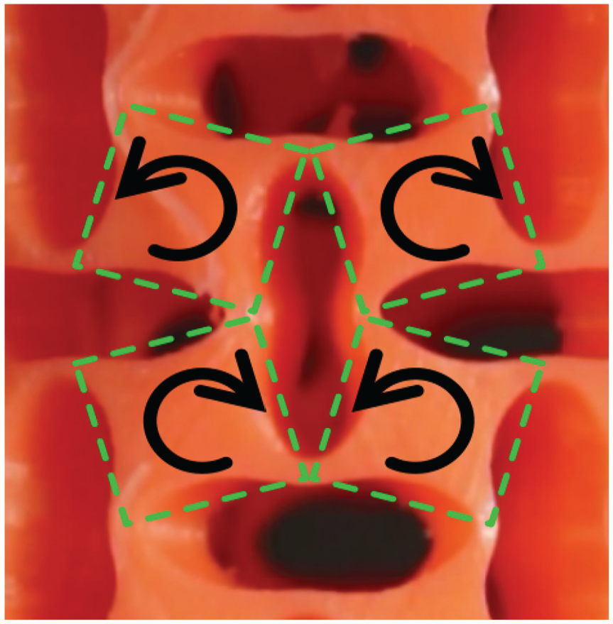
In the post-buckling stage of the deformation, the solid parts between the holes behave approximately as rigid square plates, and rotate in an alternating pattern. These squares are indicated with dashed lines and the direction of rotation for each of the plates is indicated by arrows.
In both stages of the deformation, the overall structure of the tube remains approximately cylindrical. In previous studies of this structure, it was shown that this is the case whenever the beams between the holes are sufficiently slender with respect to the size of the holes [33].
3. Two pseudo-rigid body models for post-buckling behavior
In this section, we introduce the spatial PRBMs used to analyze the elastomeric tubular structure, one including the clamping of the ends, and one without clamping. Both models are based on the same mechanical structure, illustrated in Figure 4(a), where the clamping has been included. The structure consists of
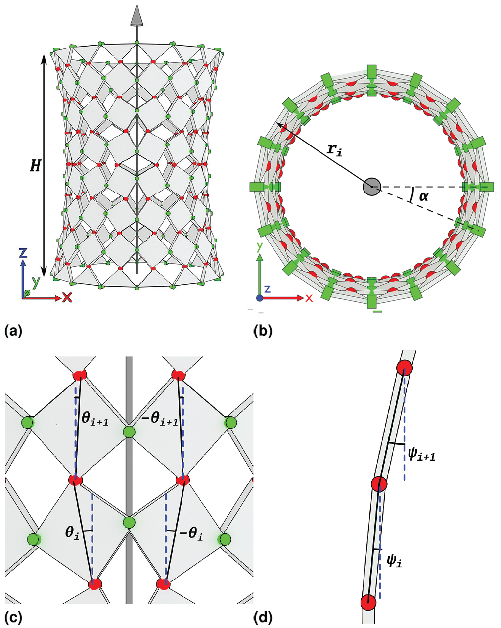
(a) The pseudo-rigid body model of the elastomeric cylindrical metamaterial structure consists of rigid squares, coupled at their corners. (b) Each square occupies a fixed sector angle
Each square in a layer can rotate about an axis normal to its surface and crossing its center. We call this rotation angle
The radius

where l is the length of the diagonal of the squares. The height of a layer, measured along the

The squares in consecutive layers are coupled at their corners, such that these corners share their radial and

The total height of the modeled structure is

where the heights of the top and bottom layers have been halved to reflect the flat top and bottom surfaces of the elastomeric structure.
We add stiffness to the model by adding torsion springs to the connections between the squares, as illustrated in Figure 5. Within a layer, we place torsion springs at each connection, oriented radially (Figure 5(a)). For this, we define the rotation angle
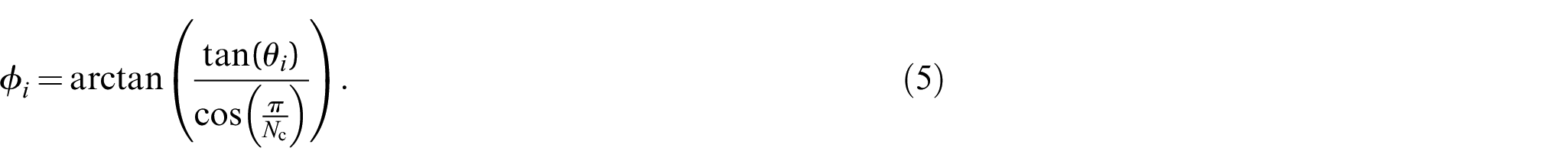
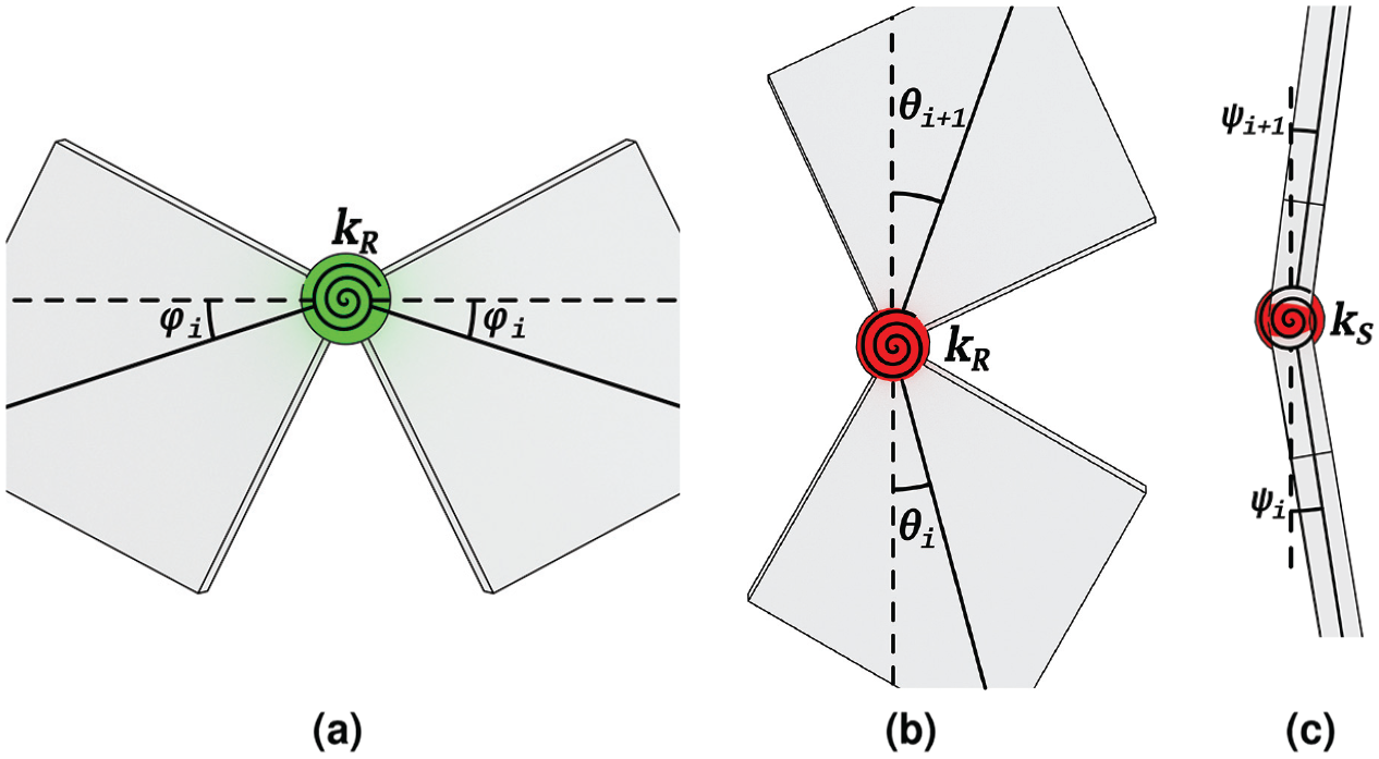
Three types of torsion spring are used to model the stiffness of the elastomeric structure in the pseudo-rigid body model. In the horizontal connections (green), there are radially oriented (a) torsion springs. In the vertical connections (red), there are both radially oriented (b) and tangentially oriented (c) torsion springs.
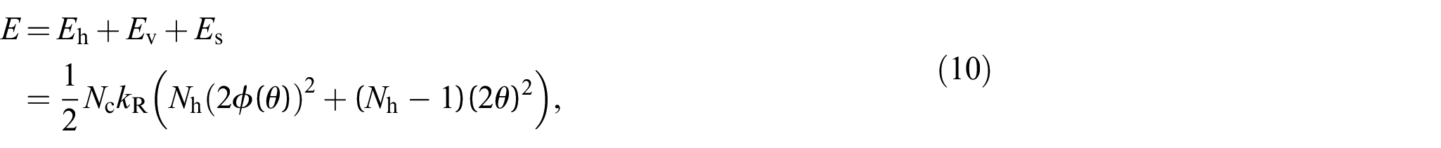
The energy in these torsion springs is then

where
Between the layers, we place two springs at each connection, one oriented radially and one tangentially to the cylindrical surface. The stiffness of the radially oriented springs is equal to that of the previously described radial springs within a layer. The radial springs are illustrated in Figure 5(b). The energy in these springs is

The energy in the torsion springs placed tangent to the cylinder is

where
We implement this model in two distinct ways: a simplified one-degree-of-freedom (1-DOF) model with free boundaries, and a model with
3.1 1-DOF model
In the simplified model, we take all

Because the radius is constant along the height of the cylinder, we have
where the sums over the layers have been evaluated.
3.2.
-DOF model
In the second model, we constrain the top and bottom boundary of the structure in the radial direction by setting
This model is evaluated numerically for a range of vertical strains
4. Pre-buckling estimation
To estimate the stiffness of the structure in the pre-buckling regime, as well as the buckling threshold, we model the structure as

The reaction force of the structure in the pre-buckling stage is then

where H is the current height of the structure and
The buckling transition is then assumed to occur at the point where the force–displacement graphs of the pre-buckling and the post-buckling model intersect.
5. Experimental validation
5.1. Methods
For the experimental validation of the PRBM, we constructed a porous cylinder with
The structure was compressed by a universal testing machine (Zwick/Roell AG, Ulm, Germany). The cylinder was placed between two acrylic plates, which were covered in masking tape to reduce reflections. The cylinder was compressed by 8 mm, at a rate of 5 mm/min, during which a digital camera (Canon EOS 70D) was used to acquire image data. Using the image data and image recognition software (Python3 with the OpenCV2 module), the width of the central 10% of the cylinder was determined during compression.
The experimental data were compared with both models. The stiffness of the torsion springs and the pre-buckling linear springs were calculated for notch hinges with radii of 9 mm, a minimum thickness of 1.13 mm and a height of 8.45 mm [35]. The Young’s modulus of the material was taken to be 0.67 MPa. These, and other parameters for the model, were measured on the silicone structure. The used values are presented in Table 1.
Parameters of the PRBM for validation.

5.2. Poisson’s ratio
Figure 6 shows the observed radial strain

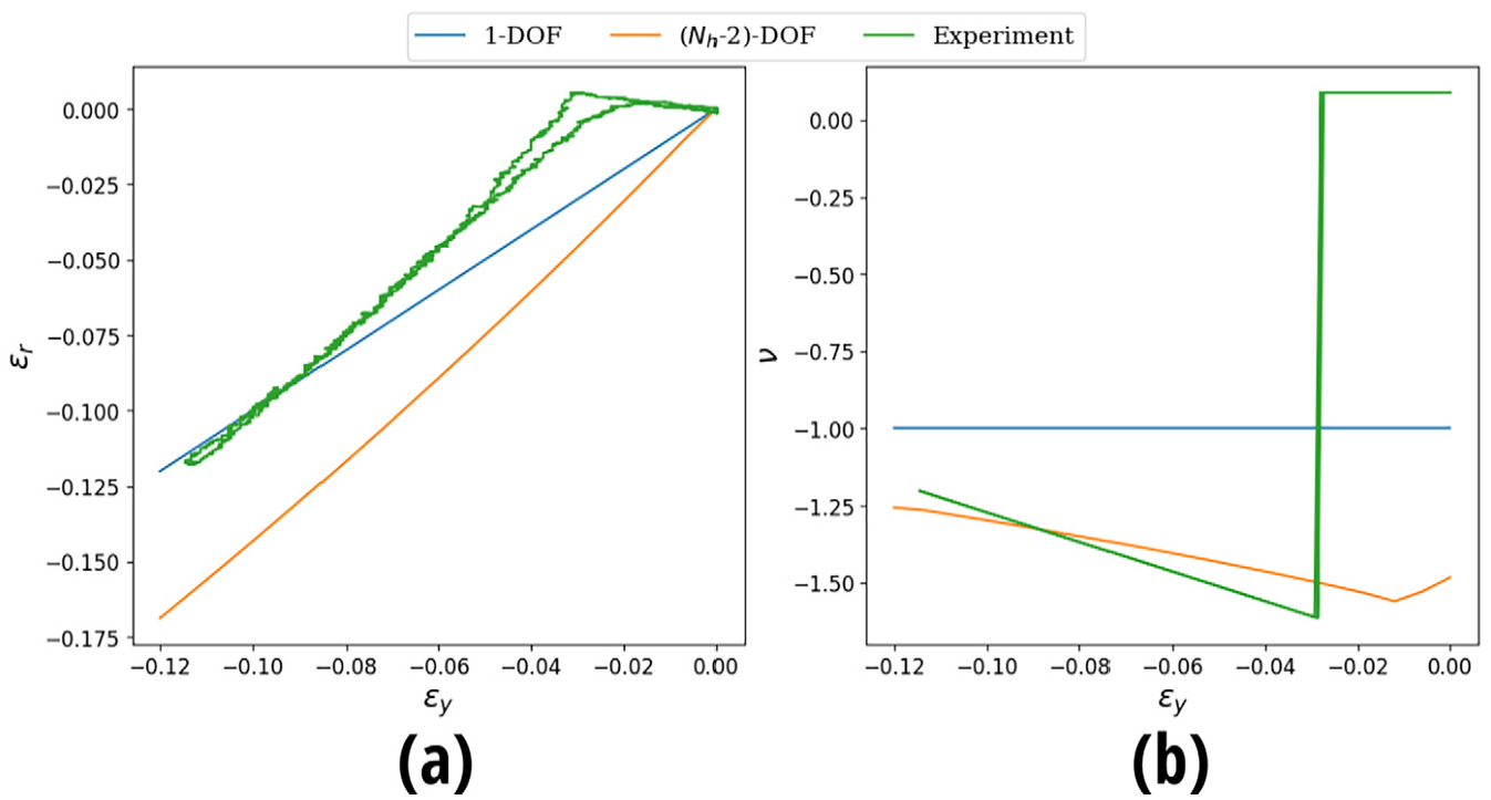
Plots of (a) radial strain and (b) ratio as a function of the applied vertical strain on the structures. Shown are the data from the experiment (green), and the calculated values for the one-degree-of-freedom (blue) and
We fit a linear function to deformation in the pre-buckling behavior and a quadratic function to the post-buckling behavior. The Poisson’s ratio is then determined as the negative derivative of this function with respect to the applied strain
In Figure 6(b), we see that the 1-DOF model predicts a Poisson’s ratio of
Figure 7 shows the shapes predicted by the
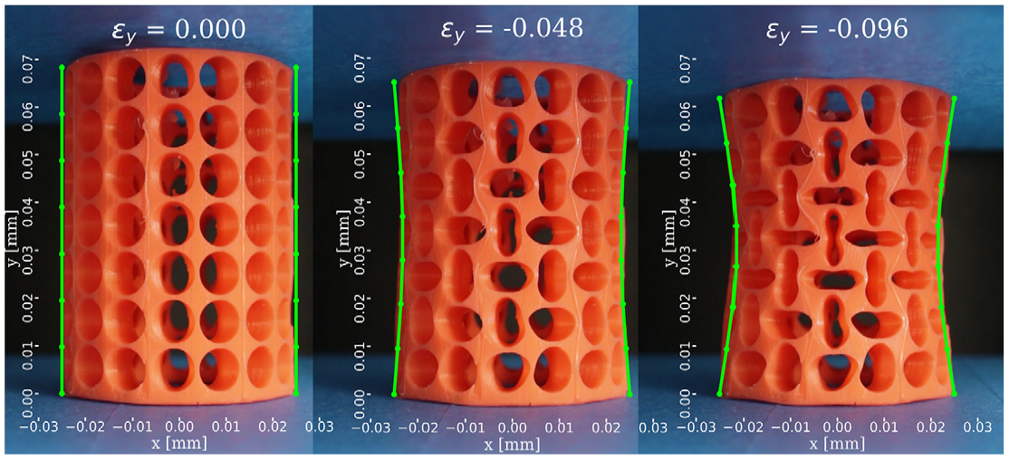
Three snapshots of the elastomeric structure during the compression test, with the shape calculated by the
5.3. Force–displacement behavior
Figure 8 shows the force–displacement behavior measured on the elastomeric structure and predicted by the two PRBMs. In the experiment, we observe a steep increase in the reaction force up to the buckling point, after which the force is close to constant, around 3 N. Both models predict close to constant force–displacement behavior, but overestimate the total force by approximately 0.43 N and 0.14 N, respectively. The N-DOF model predicts a lower total force because the square plates in the top and bottom layer do not rotate and therefore the torsion springs in these layers are not loaded, which is closer to reality.
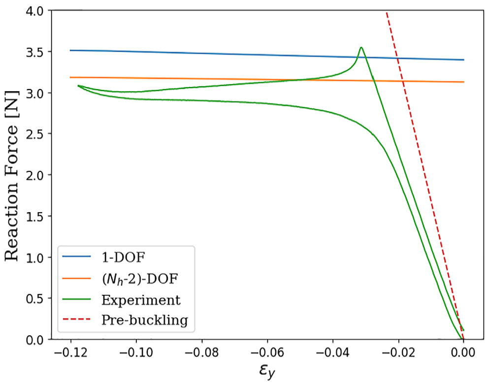
Plots of the force–displacement behavior of the cylindrical structure. The green line shows the experimental data. The blue and orange lines show the calculated post-buckling behavior of the structure as calculated using the 1-DOF and
In the experimental results, we observe a buckling transition at a strain of
6. Discussion
The experimentally determined Poisson’s ratio is less than the value of
The force–displacement data of Figure 8 also shows a better match between the experimental post-buckling behavior and the
The observed difference between the reaction force of the elastomeric structure and that predicted by the PRBMs could also be attributable to imperfections in the elastomeric structure. The Young’s modulus used to calculate the stiffness of the joints was converted from the Shore hardness provided by the supplier of the silicone rubber and was not tested experimentally. Therefore, the elastomeric structure could have a Young’s modulus different from the value (0.667 MPa) used in the models. Furthermore, residual air bubbles or imperfect mixing of the two silicone components would also have an effect on the stiffness. A larger Young’s modulus would increase the reaction forces of the elastomeric structure, while air bubbles would decrease the stiffness of the material and therefore result in lower forces.
The buckling strain is substantially overestimated by the intersection of the force–strain curves from the pre-buckling analysis and the post-buckling models. This is due to a calculated pre-buckling stiffness that is greater than the experimental values. In the calculations, it is assumed that all deformation is localized in the notch joints, just as was done for the post-buckling analysis. From the experiments, we observe that this assumption might not be valid. If there is also deformation in the square parts of the structure, the total stiffness of the structure will be smaller since the deformation is more evenly spread throughout the structure. This would result in a buckling transition at lower values of the strain.
The 1-DOF PRBM presented in this paper can be solved analytically and is therefore useful for calculating a quick estimate of the properties of the metamaterial under ideal compression conditions. However, as we see in the experimental validation, it is unable to replicate the significant effects of the boundary conditions. The
7. Conclusion
In this paper, we have demonstrated the application of two PRBMs to a spatial mechanical metamaterial. This was achieved by analyzing a cylindrical mechanical metamaterial with a negative Poisson’s ratio. The PRBMs used for this analysis consist of rigid squares that rotate about their normals as well as around a horizontal axis tangential to the cylindrical surface. Two PRBMs were presented, a simplified version with a single variable and one with one variable per non-boundary layer of rigid squares along the height of the cylinder.
We have validated the PRBMs by measuring the Poisson’s ratio and force–displacement characteristics of the tubular mechanical metamaterial, molded from silicone rubber. The 1-DOF model captured the main features of the metamaterial in the post-buckling regime, predicting a negative Poisson’s ratio and giving a reasonable estimate for the reaction force. However, this model was unable to include the boundary conditions introduced by clamping of the specimen in the experimental set-up, causing it to underestimate the Poisson’s ratio.
The second model, with
To obtain an estimate of the buckling strain of the structure, a simple model based on linear springs was used. This model overestimated the pre-buckling stiffness of the structure and therefore predicted a lower buckling strain than was observed in the experiment.
By analyzing spatial mechanical metamaterials using PRBMs, analytical equations for the effective material properties of these structures can be obtained. This greatly reduces the computational effort necessary to analyze these structures and can lead to a more intuitive evaluation of the complex deformation patterns that occur in these novel materials.
As the field of mechanical metamaterials grows toward the design of materials with tailored mechanical properties, fast evaluation of design iterations will become crucial. PRBMs, such as those shown in this paper, can greatly reduce the computational effort involved in these iterations, allowing for a more efficient design process.