
Abstract
Damage detection of a complex spatial frame structure with semi-rigid joints is a challenging task. Most existing damage detection methods consider the joint as rigid and the nonuniform cross section of the member is not considered. This assumption results to a large error in the structural damage identification. A novel generic element is proposed for the nonuniform cross-section member with semi-rigid joints at both ends in this study. The finite element model of spatial structures with semi-rigid joints is established using the proposed element. The modal strain energy-based damage index is defined and its sensitivity to the member and joint damage has been investigated using numerical and experimental study. An 8-m long bridge model with the bolted connection at joints is built in the laboratory. Dynamic responses of the bridge under random excitations are monitored using 13 wireless tri-axis accelerometers. The spatial mode shapes of the bridge are extracted using the reference-based stochastic subspace identification from multiple set wireless measurements. The numerical model is validated using experimental results. Dynamic responses of the bridge with different damage scenarios have been simulated using the validated model and the corresponding damage indices are obtained. The results show that the proposed method is reliable and accurate to analyze dynamic behavior of the spatial structure with semi-rigid joints, and structural damage can be identified accurately using the modal strain energy-based damage index.
Keywords
Highlights
• A generic element is proposed for the nonuniform cross-section member with semi-rigid joints. • The finite element model of large-scale spatial structures with semi-rigid joints is established. • The spatial mode shapes of a bridge are extracted from multiple set wireless measurements using reference-based stochastic subspace identification. • Numerical and experimental studies have been conducted to verify the proposed method.
1. Introduction
The large-scale spatial structures are widely used for bridge and stadium constructions. The spatial structure deteriorated due to aging and the operational and environmental loading (Adams, 2007; Jeong and Iwan, 1988; Kim and Bartkowicz, 1993). It is important to detect damage at an early stage to avoid the possible collapse of structures and conduct the repairment to extend structural service life. The structural damage detection for spatial structures has attracted the interest of researchers and engineers (Xu et al., 2022). The joint is a key component of the spatial structure and its integrity has a significant effect on the performance of the entire structure (Mehrkash and Santini-Bell, 2024). Due to the complex mechanism of the joint, it is still a challenging task to detect its damage in operational environments.
The vibration-based method has been widely used for structural damage detection of spatial structures. The change of structural dynamic properties, such as natural frequencies, mode shapes, damping, modal strain energy (MSE), frequency response function (FRF), and their variants is used to detect structural damage (Law and Zhu, 2009). The MSE-based structural damage detection is one of the most promising methods as it incorporates the system vibration behavior and physical properties (Wang and Xu, 2019). Many modal strain energy-based methods have been proposed for structural damage detection in the last two decades, including the modal strain energy change (MSEC) (Shi et al., 1998), the cross-modal strain energy (CrossMSE) method (Hu et al., 2007; Zhang et al., 2022), the modal strain energy-based index (MSEBI) (Seyedpoor, 2012), the modal strain energy equivalence index (MSEEI) (Guo and Li, 2014), and the improved modal strain energy decomposition method (IMSEDM) (Khosravan et al., 2021). However, the accuracy of structural damage identification is significantly affected by modeling uncertainties due to inaccurate physical parameters, non-ideal boundary conditions, and structural nonlinear properties (Hou and Xia, 2021).
Model updating is used to calibrate parameters of the finite element model using measurement data (Simoen et al., 2015). Finite element model updating is described as an optimization problem to minimize the discrepancy between numerical and experimental dynamic features (Solachoris et al., 2024). Evolutionary optimization algorithms and machine learning are used to solve the problem (Standoli et al., 2021). For spatial structures, multiple non-structural elements are connected at the joint with fasteners such as bolts, welds, or screws (Ding and Elkady, 2023). The mechanical properties of joints are very complicated. Joints are generally treated as pinned or fixed for structural analysis and design. The oversimplification of joint connections could lead to modeling errors (Mehrkash and Santini-Bell, 2024). It is essential to develop a reliable model for structural damage detection of spatial structures with semi-rigid joints.
Most existing methods assume that joints are either pinned or rigid for simplicity in structural damage detection (Markogiannaki et al., 2022; Nick et al., 2023). Joints are usually idealized as fully rigid in existing models (Genel et al., 2023). The flexibility always occurs at the joint as multiple non-structural elements are connected at the joint with fasteners such as bolts, welds, or screws. It has been proved that structural behavior is significantly affected by the flexibility of the joint (Jezequel, 1983). The flexibility of joints should be considered to achieve better accuracy for structural analysis (Law et al., 2001). The stiffness matrix of a member with elastic restraints at the ends was obtained by modifying with a correction matrix (Monforton and Wu, 1963). A mechanical model with three springs and a non-deformable node was proposed to analyze the behavior of the steel frames with semi-rigid joints (Ihaddoudène et al., 2009). The material and geometric nonlinearities have been considered in the numerical modeling for a spatial structure, and the influence of the joint rigidity on mechanical performance of the structure is studied (Ma et al., 2015). The semi-rigid joint model is proposed by including the joint flexibility (Paral and Samanta, 2021). Cannizzaro et al. (2024) analyzed the damaged frame with semi-rigid connections using the dynamic stiffness matrix. Recently, a two-step damage detection method for spatial frame structures with semi-rigid connections has been proposed and it was verified using a cantilever spatial frame structure by Hou et al. (2021). Joints are modeled as rotational springs and the stiffness matrix of a uniform beam element with semi-rigid joints is derived. In practice, the members at the joint are mostly with nonuniform cross-section properties due to the need to install non-structural components like bolts. Little research has been found including the nonuniform cross-section properties into the spatial structures with semi-rigid joints.
This study is to develop a generic element for the nonuniform cross-section member with semi-rigid joints at both ends, and an experimental and numerical study of spatial structures is to show its accuracy for structural damage detection. The finite element model of spatial structures is established using the proposed element. An 8-m spatial bridge model with bolted connections has been built in the laboratory. Wireless sensors are used to monitor the responses of the bridge under random excitation- and the reference-based stochastic subspace identification (Ref-SSI) method is adopted to extract the mode shapes from multiple sets of measurements. The finite element model is validated using the experimental results. Different scenarios of the bridge with the beam and joint damage are then simulated using the validated model. The modal strain energy change-based damage index is obtained for structural damage detection. The results show that the proposed method is reliable and accurate to localize both the beam and joint damage of the structure.
2. A generic element for a nonuniform beam with semi-rigid joints
2.1. The stiffness matrix of the nonuniform beam with rigid joints
In practice, the member of spatial structures consists of several segments connected by bolts. The segments have different cross-section properties. As shown in Figure 1(a), a typical nonuniform member of spatial structures with three segments, for example, a uniform middle beam and two end beams with small cross sections. An equivalent uniform beam is shown in Figure 1(b). In this section, the stiffness matrix of the three-segment beam is obtained using the equivalent beam and joint stiffness. Nonuniform and uniform beam elements. (a) The three-segment beam element and (b) the equivalent beam element.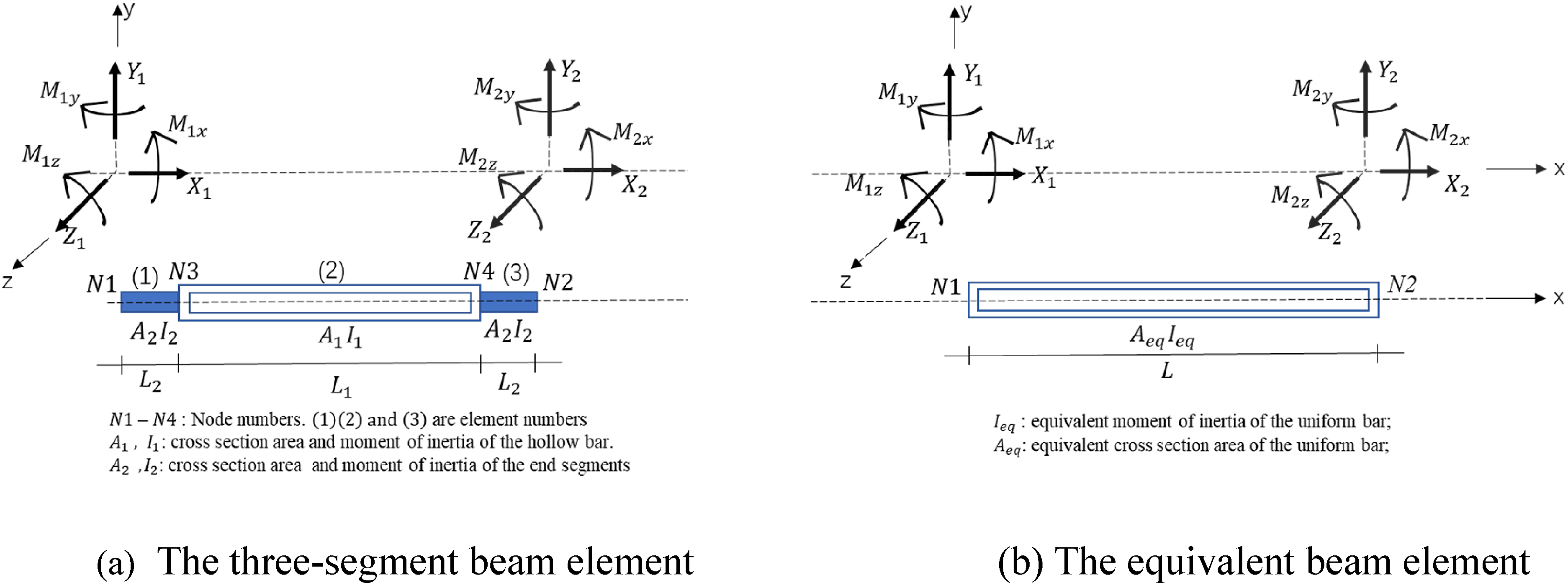
The nonuniform beam with the total length L in Figure 1(a) is divided into three uniform beam segments with four nodes. The moment of inertia I, the cross-section area A, and the length L of three segments are different. Here, I
1
, A
1
, and L
1
are for the middle segment (noted as Segment 2), respectively. I
2
, A
2
, and L
2
are for two side segments (noted as Segments 1 and 3). The subscripts y and z are about the Y and Z axes in the local coordinate system, respectively. A three-dimensional (3D) beam element has 12 degrees of freedom (DOFs), and each node has six DOFs, for example, the displacement vector {


2.2. The stiffness matrix of a nonuniform beam with semi-rigid joints
Joint connections are always simulated as pins or rigid joints while most joints behave semi rigidly with some flexibility. A 3D generic beam element with semi-rigid joints can be modeled as a beam with zero length springs at both ends. The stiffness of rotational springs at left and right ends is
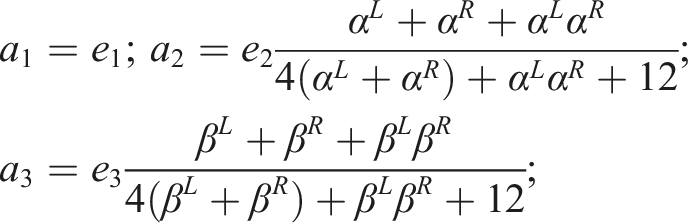
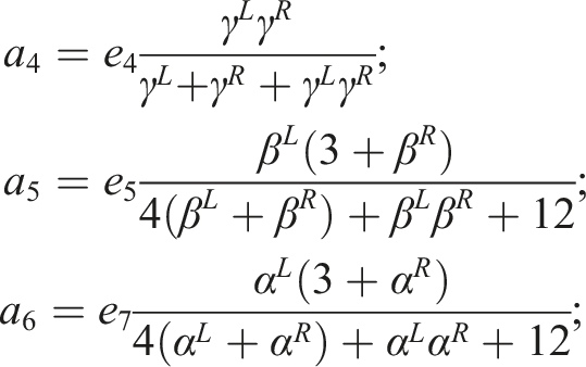
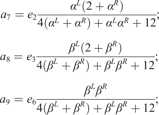
The joint rotational stiffness factor is introduced to evaluate the joint contribution to bending and it is defined as the ratio of the rotational stiffness
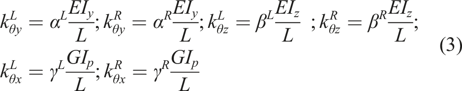
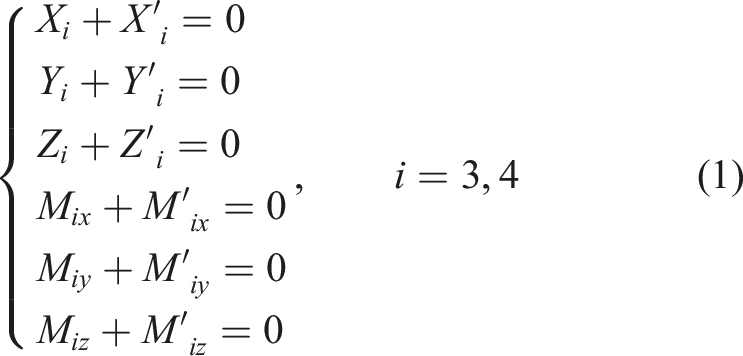
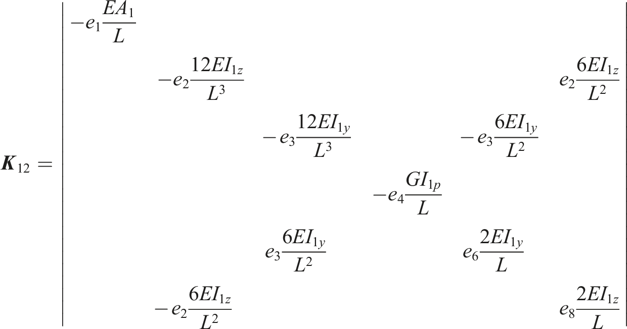
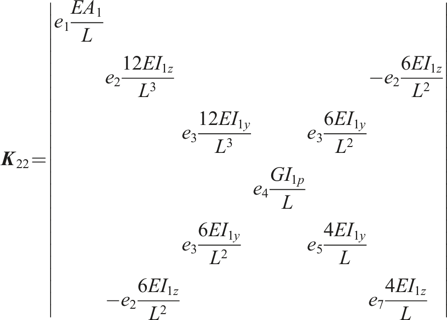
The above stiffness factors represent the rigidity of the semi-rigid joint. The joint damage is defined as the rotational stiffness reduction. The stiffness matrix of the beam element with semi-rigid joints can be obtained by introducing these factors into equation (2). The stiffness matrix of the nonuniform cross-section beam with semi-rigid joints can be represented as,
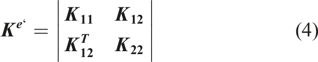
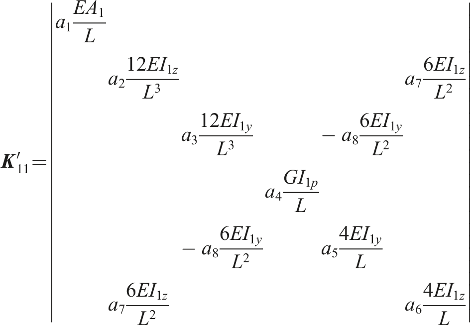
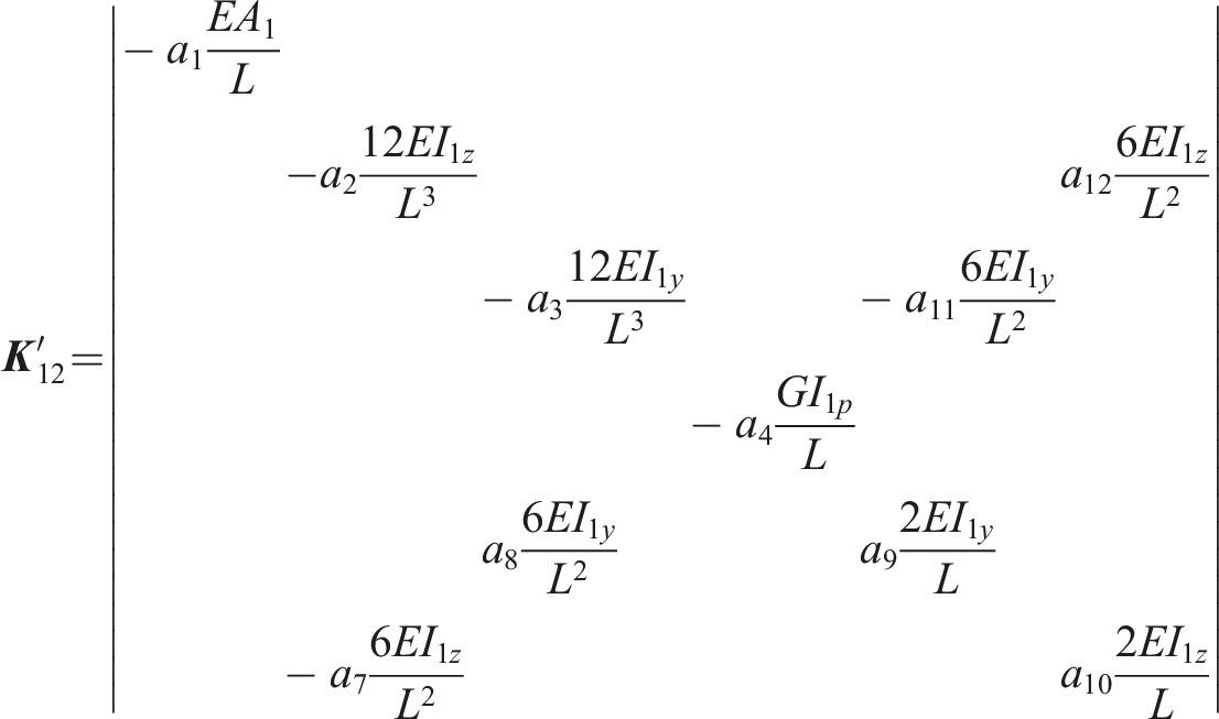
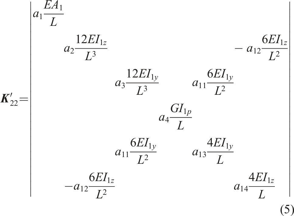
The parameters
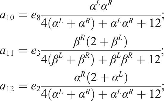
Equation (4) represents the stiffness matrix of the generic element for a nonuniform beam with semi-rigid joints. The element can be incorporated into the finite element model of the spatial structure.
2.3. The modal strain energy-based damage index
The elemental damage is defined as the beam element stiffness reduction and the joint rotational stiffness reduction. From equation (4), the elemental stiffness matrix of a nonuniform beam with semi-rigid joints consists of several parameters, including
Structural damage leads to the stiffness reduction at one or several elements and causes changes in the mode shapes. The modal strain energy of an element is defined as the product of the elemental stiffness matrix and the mode shapes as (Shi et al., 1998), Flowchart of the method.

3. Experimental setup and modal analysis
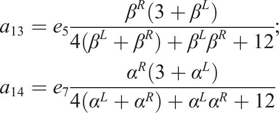
The experimental study is conducted to verify the accuracy of the proposed finite element model in this section. The dynamic responses of the bridge under random excitations have been monitored using the wireless sensor network. Modal parameters of the bridge are extracted using the reference-based stochastic subspace identification (Ref-SSI) method (Peeters and De Roeck, 1999). The experimental results are compared with that using the finite element model.
3.1. The bridge model
A spatial bridge model has been built in the laboratory and the details of the spatial frame bridge model are introduced in this section. Figure 3 shows a 14-span spatial frame bridge with 7.98 m long, 0.6 m wide, and 0.6 m high. The model was built according to the design specification by Gao and Spencer (2007). The bridge is simply supported with a pin at the left end and a roller at the right end. For the pin support, except for the rotation about the x-axis, other displacements and rotations are constrained. For the roller support, the longitudinal displacement and the rotation about the x-axis are allowed and others are constrained. The bridge consists of 160 tubular beam members and 56 joints. There are two kinds of beam members, for example, the diagonal and non-diagonal members. All beam members are nonuniform and two end portions are solid segments of 10 mm diameter connected with the middle part by screws. The length of the solid segment is 100 mm. The cross section of the middle part is with an inner diameter of 12 mm and an outer diameter of 18 mm. The length of the middle part for diagonal members is 600 mm while it is 400 mm for vertical and horizontal members. The members are connected at joints by bolts. Experimental setup.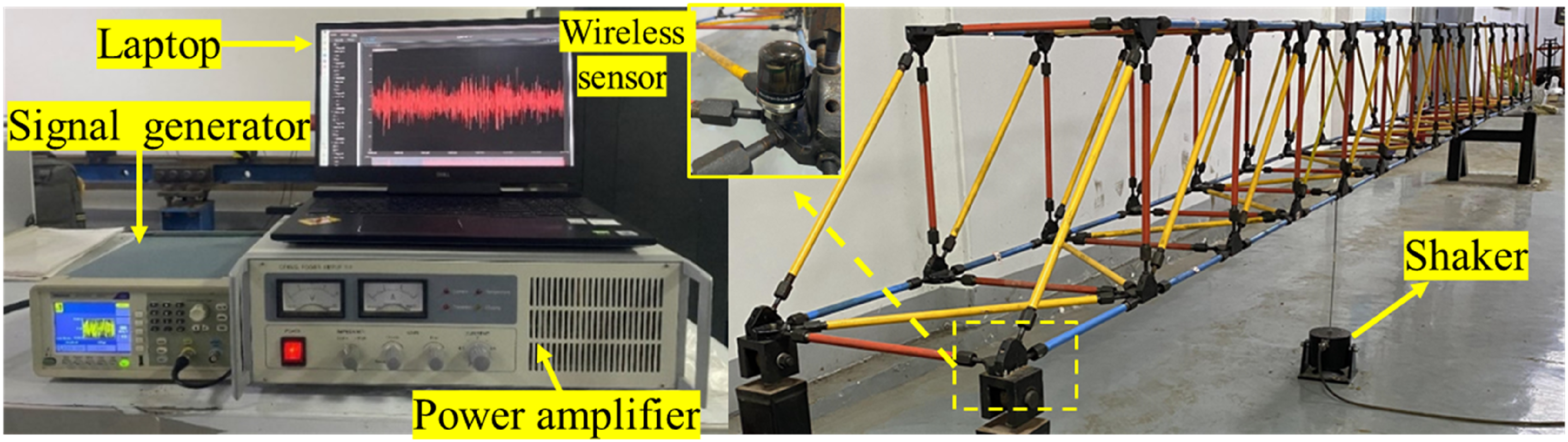
3.2. Experimental setup
The dynamic responses of the spatial bridge model subjected to random excitations are monitored using wireless sensors. Figure 3 shows the experimental system including a power amplifier (CF6502), a shaker (CF6900-100), a signal generator (AFG1022), 13 wireless tri-axis accelerometers, and the wireless data acquisition system. The shaker was connected to the bridge on the fifth joint from left of the lower chord through a stinger. The white noise signal with an amplitude 10 V was generated by the signal generator and amplified by the power amplifier and then the excitation force was applied on the bridge joint through the stinger. The tri-axis wireless accelerometers were installed on the upper surface of joints through strong magnetic blocks. The sampling frequency is 256 Hz and the responses at horizontal (X) and vertical (Z) directions were recorded. The recording length for each test is 20 min.
To get spatial mode shapes of the bridge, four measurement sets were recorded. The locations of accelerometers for Sets 1–4 are shown in Figure 4, and each set is corresponding to one longitudinal edge, which is the pink dash line in the figure. For each measurement set, eight accelerometers were installed evenly on one edge along the longitudinal direction of the bridge and another five accelerometers were used as reference. Four accelerometers (No. 5–8) in the middle span of the bridge and another accelerometer (No.13) were used as reference points. Upon finishing one edge measurement, eight accelerometers were moved to the next edge and the reference accelerometers were stayed stationary. Accelerometer locations of four set measurements.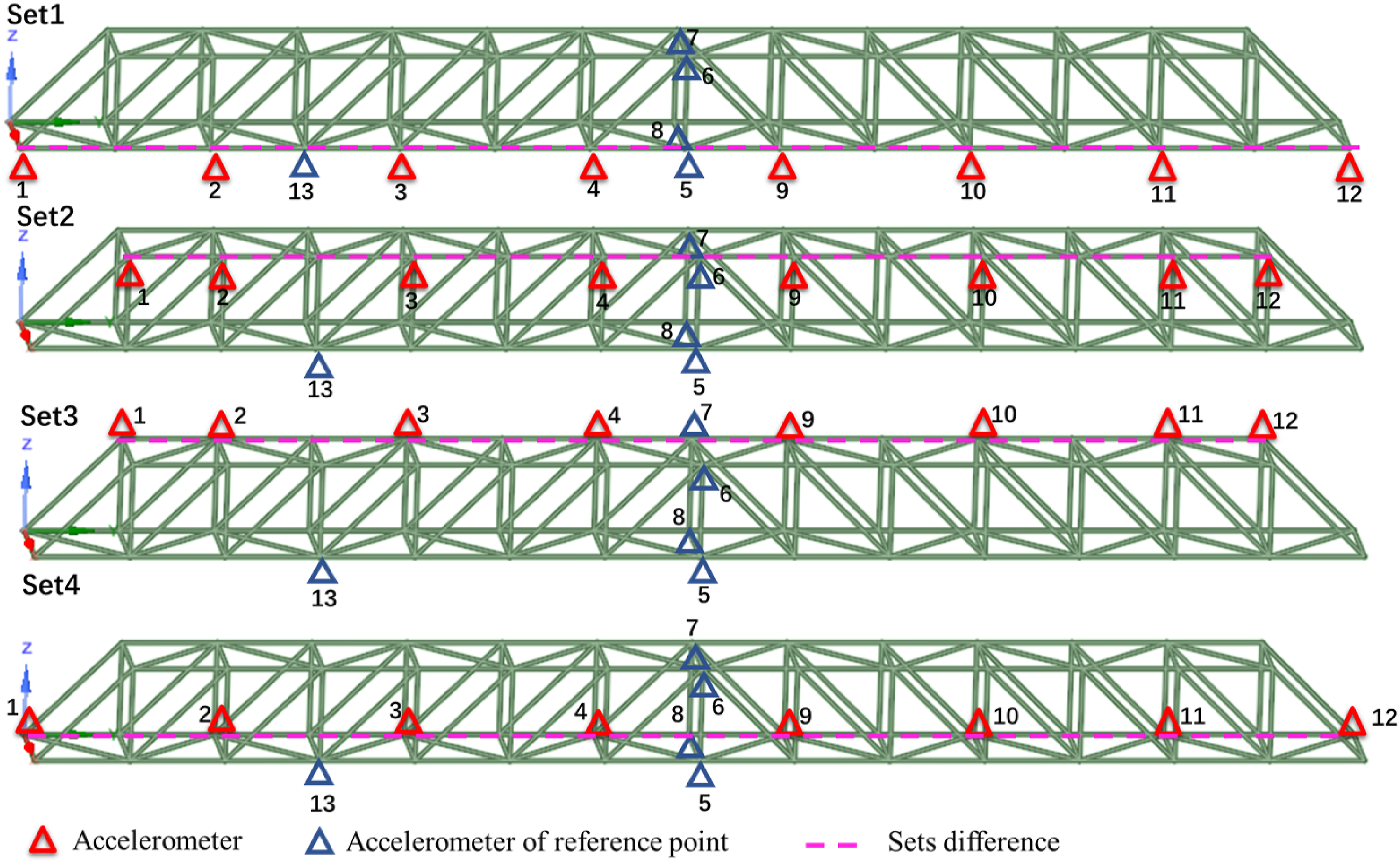
3.3. Ref-SSI-based spatial mode shapes extraction using multiple set measurements
Spatial mode shapes were extracted from four set measurements using the Ref-SSI method. First, the stochastic subspace identification (SSI) method was conducted on each set of measurements to obtain corresponding natural frequencies and local mode shapes of each edge. Then, with Ref-SSI method, spatial mode shapes were obtained by combining the mode shapes of four edges through rescaling. A rescaling procedure is conducted as (Amador and Brincher, 2021),
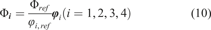
Figure 5 presents the first six spatial mode shapes. The corresponding natural frequencies are obtained as 14.6 Hz (bending), 23.4 Hz (torsion), 39.5 Hz (torsion), 45.7 Hz (bending), 57.8 Hz (torsion), and 71.9 Hz (bending). The results also show that the diagonal values of the modal assurance criterion (MAC) matrix (Allemang, 2003) are close to one while the values at other locations are very small, and that indicates no coupling effect between these modes. Experimental and numerical mode shapes of the bridge.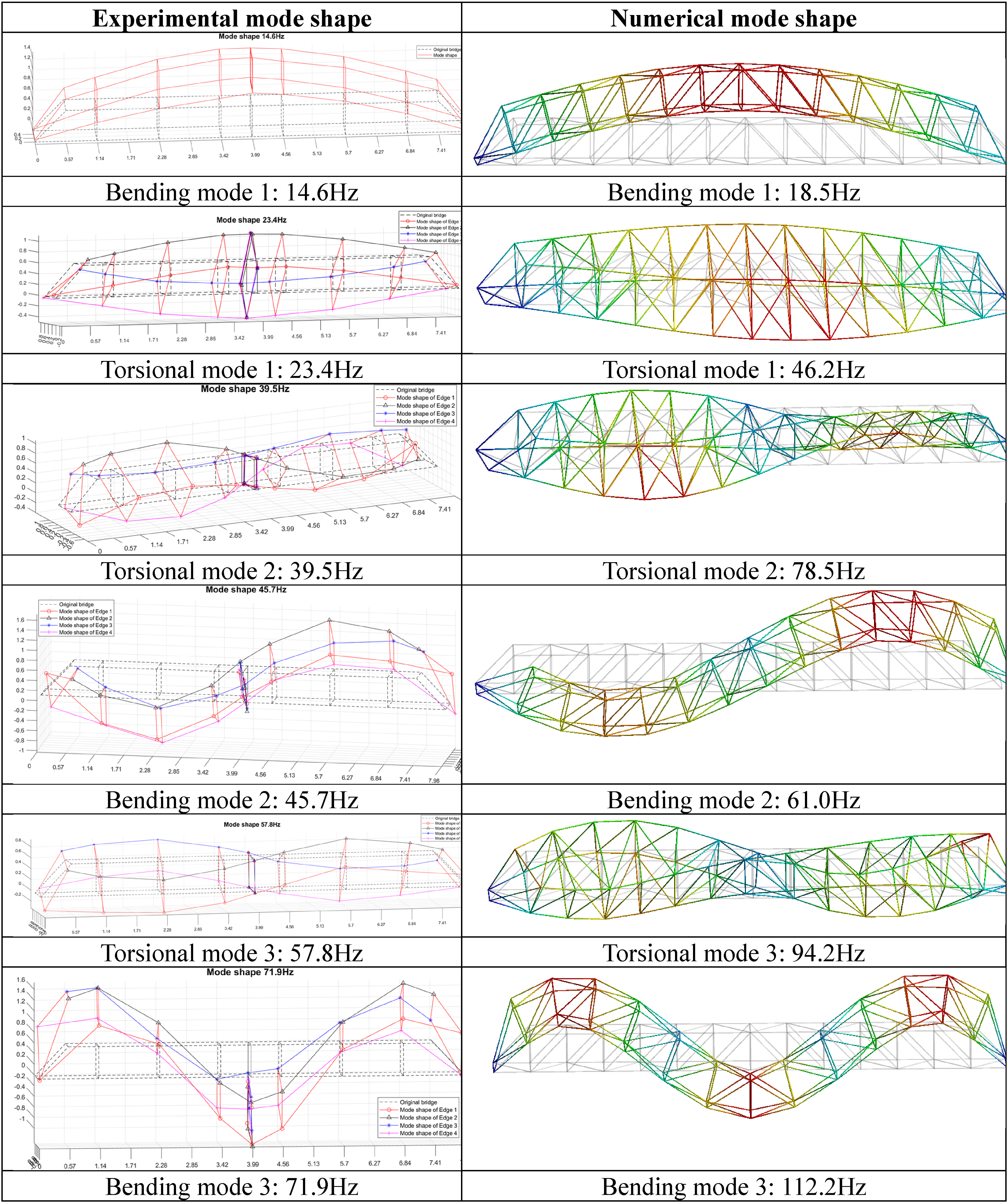
4. Finite element model validation
4.1. Numerical model
The finite element model (FE model) of the bridge is established using ANSYS 19.0. The displacements in X, Y, Z directions at the left end support are constrained, and the displacements in X, Z directions at the right end support are constrained and the displacement in Y direction is free. The member of the bridge model is modeled by the Beam4 element with an uniform circular tube section. The properties of the beam component are Young’s modulus
4.2. Comparison of experimental results and numerical results with the rigid joint model
Natural frequencies of experimental and numerical models and the MAC values.
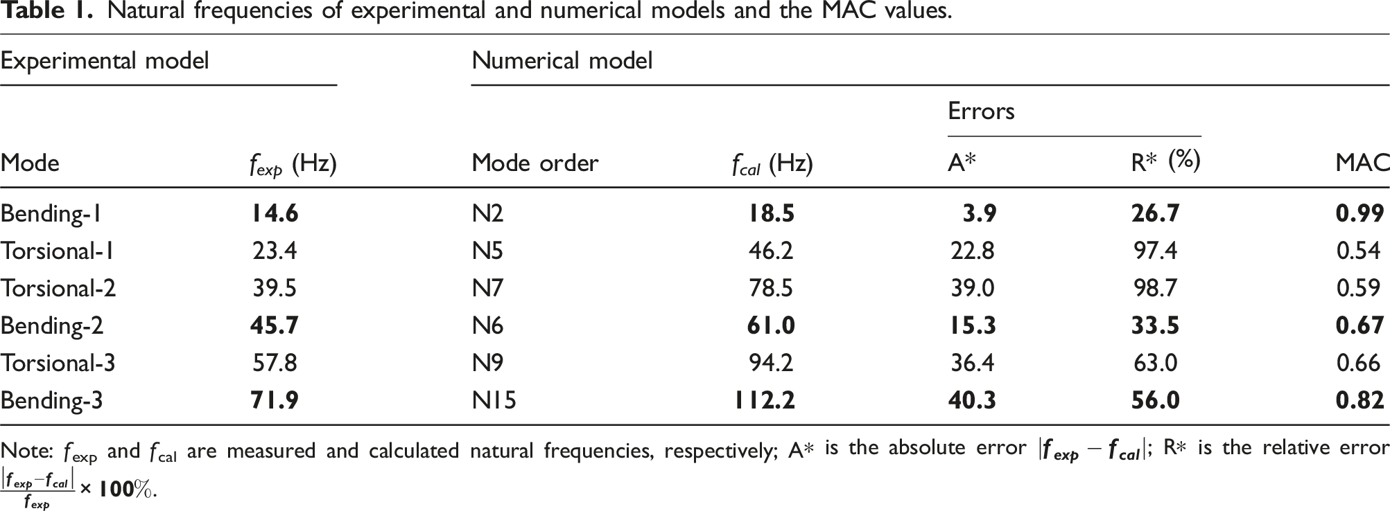
Note: f exp and f cal are measured and calculated natural frequencies, respectively; A* is the absolute error
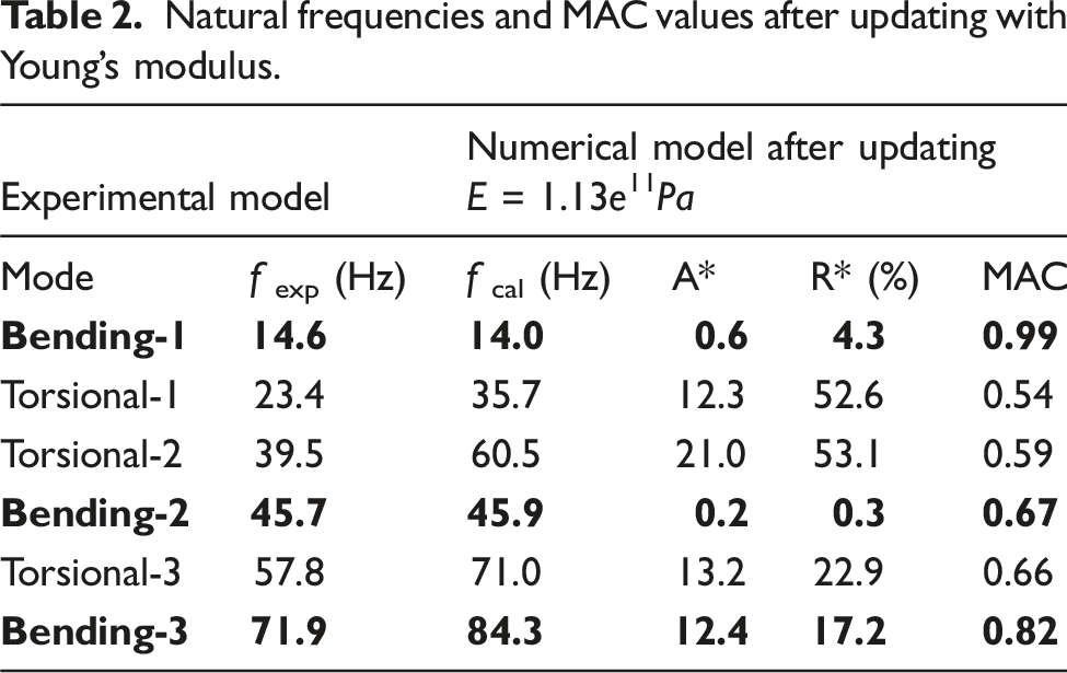
4.3. Finite element model updating with semi-rigid joint model
In this section, finite element model updating has been conducted in two-steps. In the first step, the beam element stiffness is updated to match bending modal frequencies of experimental and numerical models. In the second step, both the beam elemental and joint stiffness are updated to match torsional frequencies.
4.3.1. Member elemental stiffness updating
As shown in Figure 4, the bridge beam components are nonuniform three segment beam elements while an equivalent uniform beam element is used in the numerical model. This effect could be considered by elastic modulus reduction. The objective function is defined as the discrepancy between experimental and numerical results of natural frequencies. Three objectives were investigated as defined below, Objective 1 considers all six modes as follows: Objective 2 considers three bending modes only as follows: Objective 3 considers three torsional modes only as follows:
For the spatial structure with rigid joints, the elastic modulus is updated. Figure 6 shows a comparison of results using three objective functions. From the results, the optimum elastic modulus values by F1 and F3 are much smaller than that by F2. This is due to the flexibility of joints and the nonuniform cross-section member of the structure have not been considered, which has a large effect on torsional modes. The objective function Comparison of three objective functions. Natural frequencies and MAC values after updating with Young’s modulus.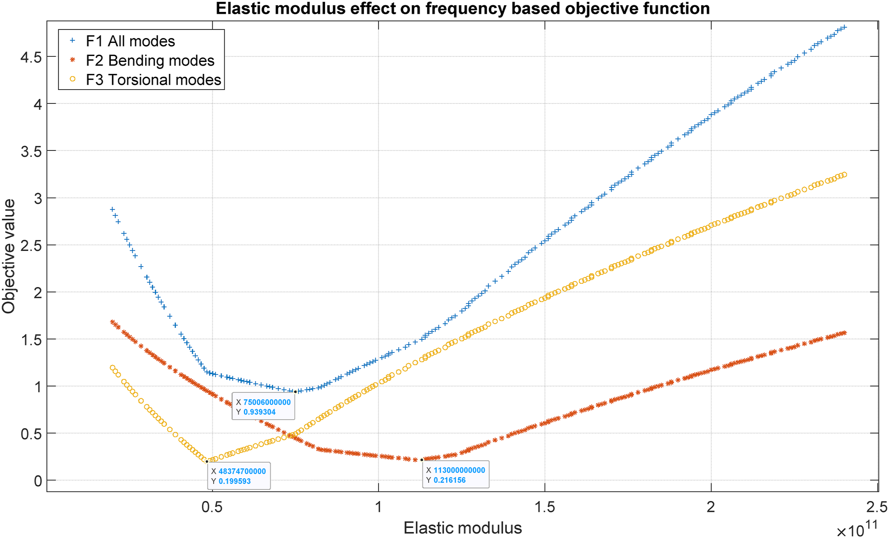
4.3.2. Joint rotational stiffness updating
Natural frequencies and MAC values after updating with joint and beam stiffness parameters.
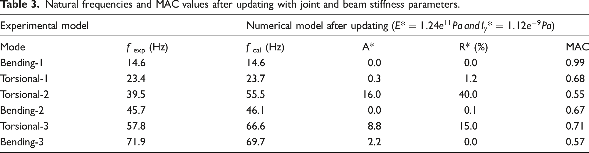
As the above, equivalent Young’s modulus
5. Structural damage detection using the semi-rigid joint model
5.1. Scenarios description
To evaluate the performance of the proposed model for structural damage detection, various damage scenarios were simulated. Due to the limited sensors, the numerical study has been conducted to verify the performance of the proposed method in Section 5.1. As shown in Figure 7, the elements were numbered along the truss bridge Elements’ number.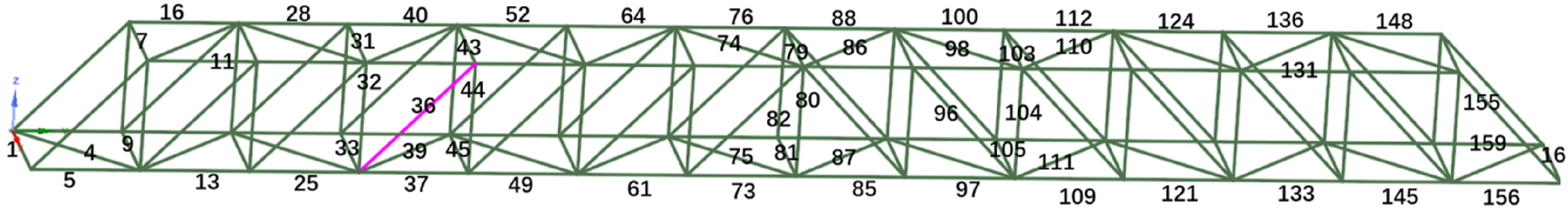
5.2. Structural damage identification using the semi-rigid joint model
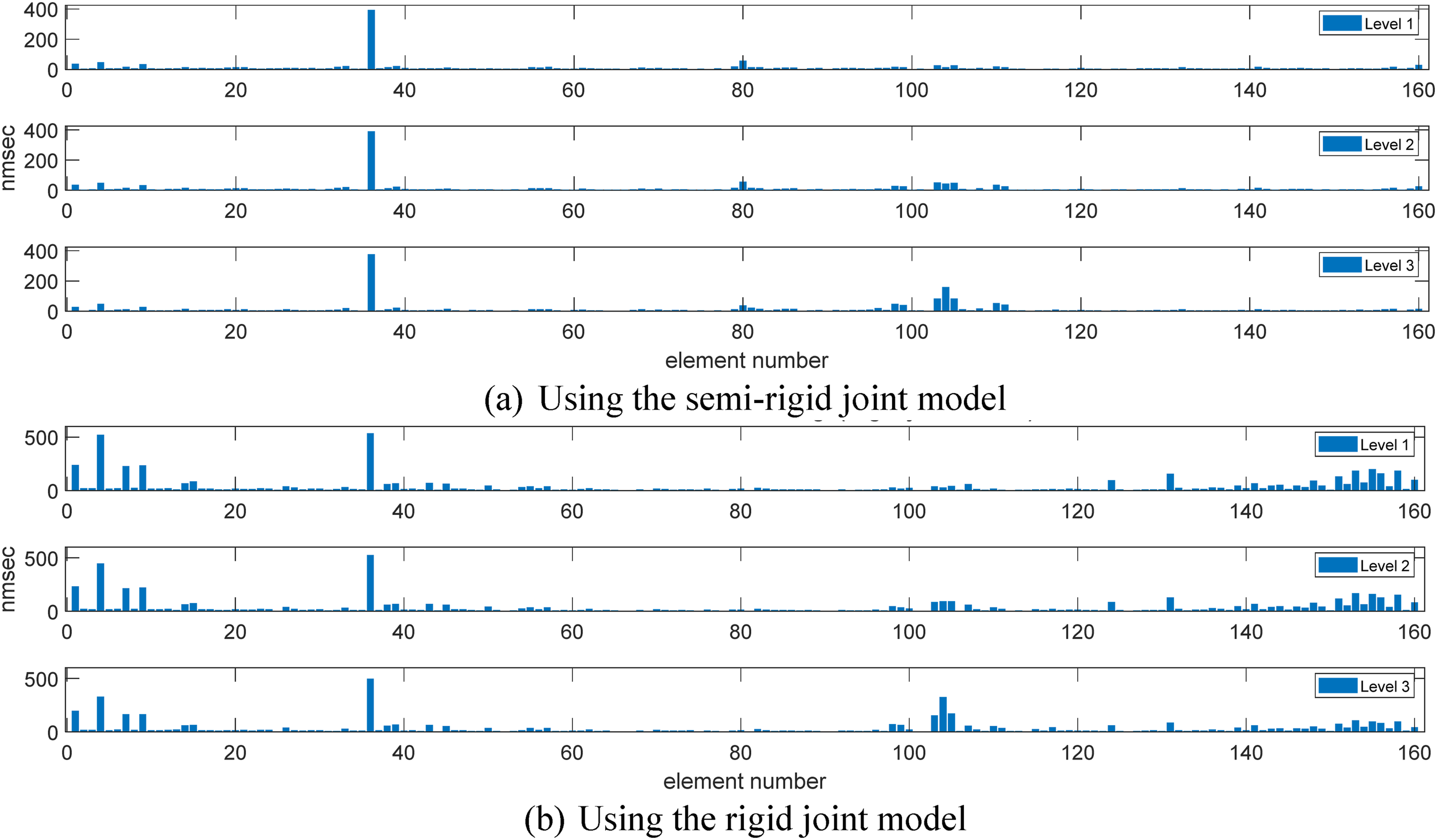
Elemental damage index nmsec of two damage scenarios including (1) damage of diagonal beam element 36; (2) vertical beam element 104; and (3) double damage scenarios using the semi-rigid and rigid joint models were calculated. Figure 8 shows the nmsec values of the structure with the damage in a diagonal member using the semi-rigid and rigid joint models. The nmsec values of the structure with the double damage were shown in Figure 9. From Figure 8(a), the damaged beam is identified clearly for a diagonal element damage scenario using the semi-rigid joint model. The nmsec value is increased with the damage level. Figure 8(b) shows the results using the rigid joint model and there are large errors at the two ends of the bridge. Similar observations are also obtained from Figure 9. As shown in Figure 9, the damage in the diagonal member is more clearly identified than that of the vertical member. The damage could be identified clearly using the semi-rigid joint model compared with the rigid joint model. The nmsec values for the structure with a diagonal beam damage. (a) By semi-rigid joint model and (b) by rigid joint model. The nmsec values for the structure with double beam damage. (a) Using the semi-rigid joint model and (b) using the rigid joint model.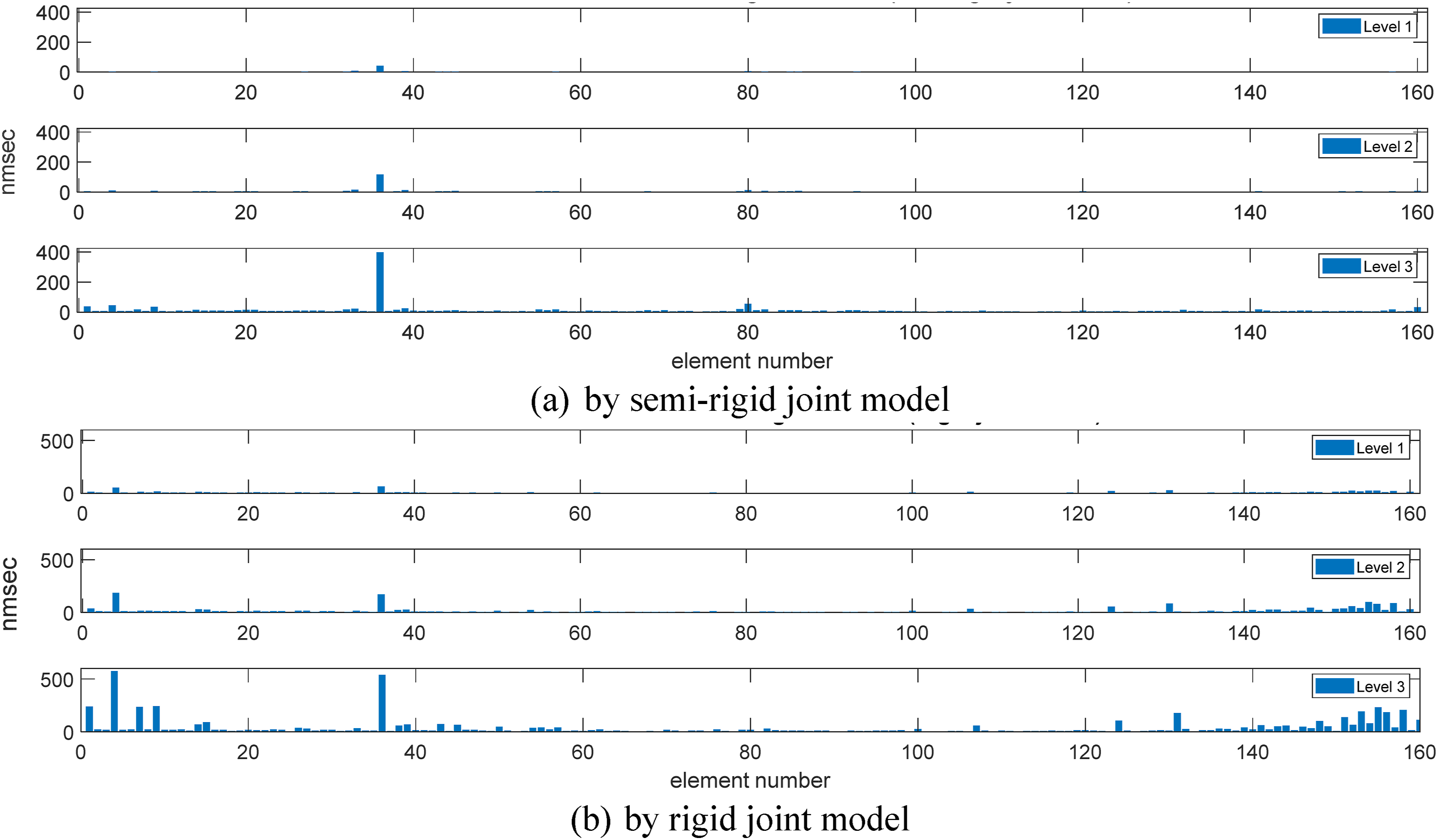
5.3. Joint damage identification using the semi-rigid joint model
This section investigates the joint damage detection of the frame structure. All damage scenarios and damage severities are simulated as in Section 5.1 except that the joint damage is simulated by reduction of I
y
The nmsec values for the structure with three joint damage scenarios are shown in Figure 10. Unlike beam damage, the joint damage inevitably influences nearby connected elements. From the figure, the joint damage could be detected for all scenarios around 1/3 span. In Figure 10(a), Element 36 and its nearby elements (Elements 33–44) show a higher nmsec value. In the joint damage around the diagonal beam 36 (Figure 10(a)) and double joint damage (Figure 10(b)), some elements at the middle span (Beam 80–86) also show slightly higher nmsec values. In numerical simulation, the finite element model includes 160 beam elements and the frequencies and mode shapes of the structure are obtained. To simulate the experimental study in Section 3, only the first six modes are used in the calculation of the nmsec values. The error in the middle span is due to the limited number of modes. In all scenarios, the nmsec value increases with the damage level, and it could be used to indicate the severity of the joint damage. The nmsec values for the structure with double joint damage. (a) Joint damage at two ends of Beam 36 and (b) double joint damage at two ends of Beams 36 and 104.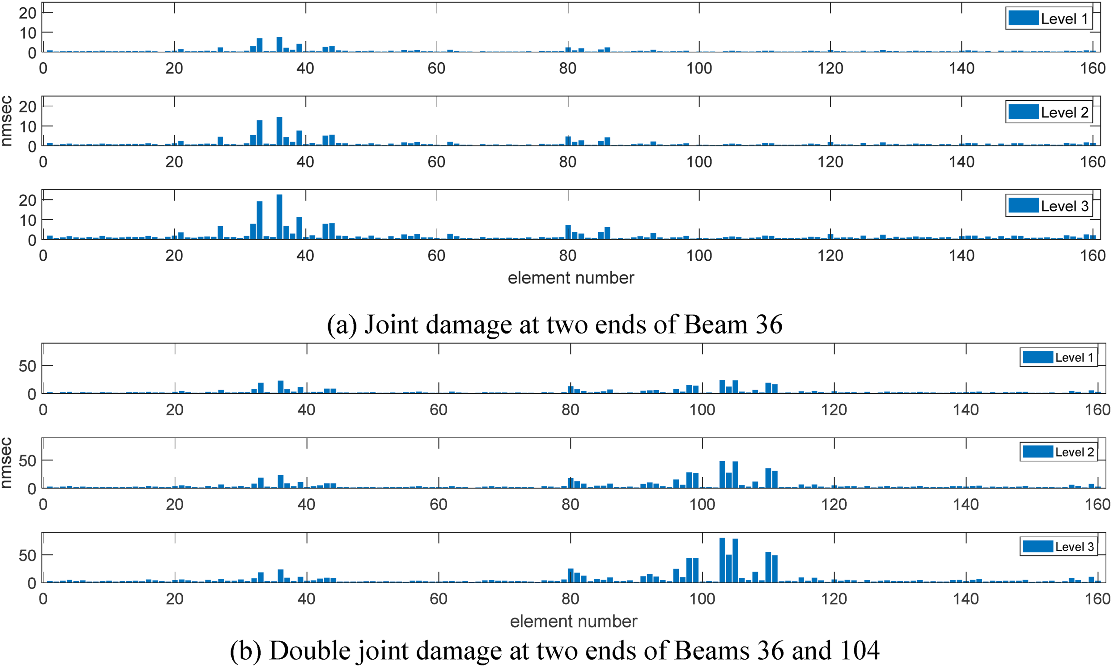
6. Conclusions
A novel generic element for nonuniform cross-section beams with semi-rigid joints at both ends has been developed, and the finite element model of the spatial structure with nonuniform cross-section members and semi-rigid joints is established. The modal strain energy-based damage index has been proposed for structural damage detection. The following conclusions can be obtained: 1) Numerical and experimental results show that the proposed generic element is accurate and efficient to analyze the spatial structure with semi-rigid joints, and it is essential for effective structural damage detection. 2) Numerical results show that the joint and member damage of spatial frame structures could be detected using the modal strain energy-based damage index. Compared with existing methods with the rigid joint model, the damage of beam members can be identified accurately using the semi-rigid joint model. 3) Numerical results show the effectiveness of the modal strain energy-based damage index for structural damage detection of spatial structures with semi-rigid joints. Further experimental study is needed for practical applications. Next step is to create a surrogate model based on machine learning for structural damage detection of complex spatial frame structures in practice.
Footnotes
Declaration of conflicting interests
The author(s) declared no potential conflicts of interest with respect to the research, authorship, and/or publication of this article.
Funding
The author(s) disclosed receipt of the following financial support for the research, authorship, and/or publication of this article: This study was supported by the Australia Research Council (ARC) Discovery Project (DP) No.: 23010806.