
Abstract
A particle damper is a passive damping device, which relies on the high dissipation properties of granular materials. During structural vibration, kinetic energy transfers to the particle damper, initiating collisions among particles and with cavity walls. This interaction results in friction-based dissipation, leading to a reduction in the supporting structure’s vibration amplitude. The granular materials enclosed in the particle dampers undergo significant dynamic loads over the course of their lifespan. The consistent dynamic stress encountered by granular materials might alter the vibration attenuation capability of a particle damper. Therefore, it is crucial to examine the vibration mitigation performance of a particle damper after subjecting it to substantial dynamic loads before implementing it in real-world applications. Hence, the present contribution aims to experimentally investigate the vibration attenuation capability of particle dampers subjected to dynamic loading at 85 million, 165 million, and 330 million cycles. Furthermore, the particle dampers under investigation have also been exposed to a temperature cyclic load ranging from 30°C to 120°C. The experimental investigation shows that there is no negative effect on the vibration mitigation performance of the particle dampers before and after being subjected to high-impact dynamic loads and temperature fluctuations. Therefore, the granular material used in designing the particle dampers, which was studied in our previous work and subjected to long-term durability testing in the current contribution, proves to be a favorable choice. It offers advantages in terms of vibration reduction capability, reduction in additional mass, and resilience to negative effects from dynamic loading and temperature cycles.
Keywords
1. Introduction
A particle damper is a passive damping system that has gained significant attention in recent years. A particle damper consists of auxiliary masses of different shapes and sizes, which are placed within an enclosure that is attached to the vibrating structure. The auxiliary masses can also be placed inside an existing cavity of the structure (Prasad et al., 2022a). The energy dissipation due to a particle damper takes place because of the relative motion between the particles and cavity walls, as well as among the particles themselves.
The particle damping technique can become extremely attractive for industrial applications because of its conceptual simplicity, cost-effectiveness, and broadband-damping capabilities (Gagnon et al., 2019). Previous work explored various particle damper designs and their impact on wind turbine vibration through a comprehensive parametric study (placement, filling ratios, materials, dimensions) (Prasad et al., 2022a, 2022b). These laboratory-developed concepts were successfully implemented and tested in a real wind turbine generator, demonstrating significant vibration reduction (Prasad et al., 2023a; Prasad et al., 2023b). The effectiveness of three particle damper designs in mitigating wind turbine blade vibration was experimentally evaluated. The investigation focused on the influence of filling material, cavity configuration (honeycomb and tubus), filling ratios, and total damper mass (Prasad et al., 2021). All designs showed effectiveness, with one strategy demonstrating superior attenuation and successfully tested in a 50 meter blade. Previous research also examined the influence of rotational speed on particle damper performance (Daniel et al., 2023). A 1 g rubber granulate particle damper on a 15 cm blade model exhibited effectiveness only at 180 rpm (tested at 120, 180, 660, and 1080 rpm). In a study, Stauber et al. (2016) explored the impact of elastomer particles on reducing wind turbine noise and experimentally demonstrated that the advanced particle damping pod can effectively reduce vibration in the main structure across a frequency range of 100 Hz to 600 Hz. Chen et al. (2019) have utilized steel balls of a radius of 55 mm to design a particle damper in order to reduce vibration amplitude for a wind turbine tower.
Based on prior work in wind turbine applications, the successful adaptation of particle damper technology to a real-scale modular electric-drive toolkit is demonstrated by us. This approach effectively reduced vibration amplitude from the power electronic lid under operating conditions, achieving a significant attenuation of up to 15 dB (Prasad et al., 2024). Duvigneau et al. (2018) demonstrated the effectiveness of particle dampers in automotive applications. Their study showed that 0.3 mm sand particles significantly reduced oil pan vibration. Koch et al. (2017) have carried out an experimental investigation to study the effect of particle size on the vibration attenuation of an automotive oil pan. Their studies have concluded that sand with larger particle sizes and rough textures is more efficient in reducing the vibration amplitude of the oil pan.
The efficiency of particle damping technology in the spacecraft industry was examined by Veeramuthuvel et al. (2016). In their study, a particle damper was designed using three different materials: tungsten carbide, stainless steel, and aluminum alloy. The experiments revealed that employing higher-density particles significantly reduces the vibration amplitude of the PCB. Furthermore, they conducted a study to examine the impact of packing ratio on vibration attenuation and found that a 60% filling ratio effectively mitigated vibration across materials, while 100% filling offered no reduction. Simonian (1995) used tungsten powder, tungsten shot, and steel balls as particle damper to increase the damping effect in order to reduce launch load for spacecraft application (Simonian et al., 2008). Ahmad et al. (2017) investigated the impact of particle dampers on the vibration behavior of a honeycomb beam. The honeycomb beam comprised 80 cells, and only the tip of the structure was filled with acrylic balls with a radius of 1.25 mm. Throughout their study, the magnitude of the resonance peaks displayed a monotonically decreasing trend as the fill fraction increased. Michon et al. (2013) utilized soft viscoelastic particles to design a particle damper for reducing the vibration amplitude of a honeycomb beam intended for space applications. Jin et al. (2021) have demonstrated a promising application of particle damper in reducing the vibration amplitude of a hydraulic pipeline and an actual aircraft pipeline. Notably, when achieving the optimal particle filling ratio, the vibration attenuation performance of both single-unit and multi-unit systems was found to be nearly equivalent.
The efficacy of particle dampers has also been demonstrated in the domain of machinery (Goehler et al., 2014; Zhou et al., 2022). Heckel et al. (2012) developed a particle damper featuring 46 small cavities, each containing steel particles with a 2 mm diameter, to reduce saw vibration amplitude. Lu et al. (2020) have successfully investigated the effectiveness of particle dampers in mitigating the effects of random seismic excitation.
Despite the clear advantages offered by particle dampers, their extensive industrial application is hampered by two key challenges. Firstly, the mechanisms governing their energy dissipation are complex. Secondly, the performance of particle dampers is highly sensitive to numerous design parameters (material, filling ratio, particle properties, excitation intensity). Consequently, optimizing these factors for specific industrial applications remains a significant design challenge. To address this, researchers have employed extensive experimental and numerical studies to understand how these factors influence the damping performance of particle dampers (Papalou and Masri, 1996; Papalou and Masri, 1998; Lu et al., 2010; Lu et al., 2011).
The brief review presented above demonstrates a growing interest in applying particle dampers across diverse industries. These studies have primarily focused on optimizing performance by analyzing the influence of factors such as filling ratio, excitation frequency, cavity size, and particle quantity. However, it is crucial to recognize that the enclosed granular materials experience substantial dynamic loads during operation. These continuous dynamic stresses can potentially alter the properties of the granular material, impacting the wear, durability, and overall reliability of a particle damper. Since particle damper performance is highly sensitive to the condition of the granular media, a focus on ensuring their long-term viability is becoming increasingly important as their adoption in commercial applications continues to expand. This gap is aimed to be addressed by conducting a unique experiment in this study. The vibration reduction characteristics of a particle damper will be evaluated both before and after it is subjected to millions of high-amplitude dynamic loads and temperature cycles over a 20-month period. Crucial insights into the long-term performance and durability of particle dampers will be provided, aiding their reliable application in real-world scenarios.
This paper comprises eight sections, offering a thorough investigation of the long-term durability test of particle damping techniques. The section Test Specimen Design outlines the experimental specimen’s geometry. The section Experimental Setup to Measure System Response details the setup for quantifying vibration responses. The section Filling Materials and Packing Ratio discusses material selection and justification. The section Long-Term Durability Test Conditions establishes conditions for durability assessment. The section Comprehensive Workflow breaks down the entire procedure. The section Results and Discussion analyzes experimental data. Finally, the section Summary and Outlook concludes with key findings and future research directions.
2. Test specimen design
The design and the dimensions of the test specimen to investigate the effect of long-time durability test on the particle damper performance can be seen in Figure 1. Design and dimensions of the test specimen to study the influence of long-time durability tests on the particle damper performance. All dimensions are given in mm.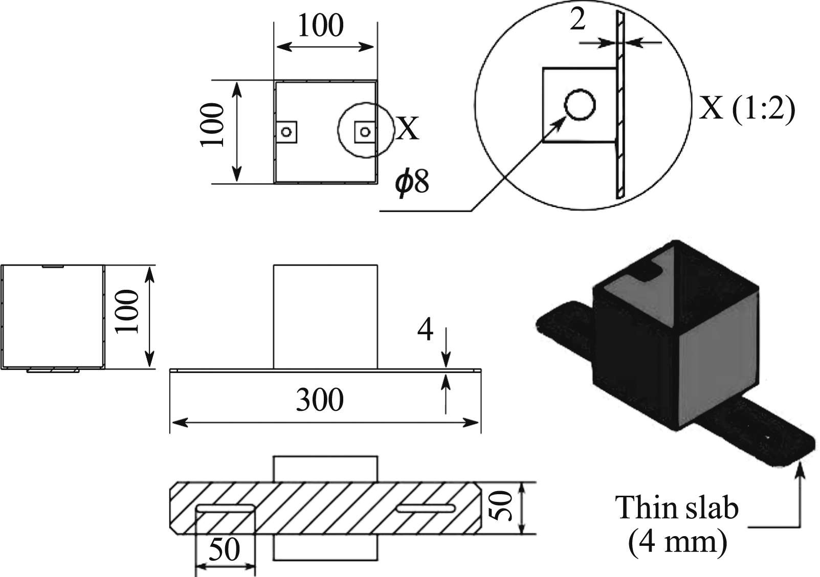
A simple box geometry was designed for the experimental investigation to facilitate later numerical model development. A 4 mm thin slab with elongated holes was welded to the bottom for secure mounting on the measuring table and decoupling. These holes also enabled attachment to the vibrating table. Five identical steel boxes were manufactured by the WRD GmbH. One box included two inner polycarbonate (PC) layers to investigate wear. The PC layers were chosen on the premise that they would experience greater wear compared to the steel walls. Additionally, two square plates with 8 mm holes were welded to the open top for lid attachment using bolts (lids only used on the vibrating table to prevent material spillage). Boxes remained uncovered during vibration measurements.
3. Experimental setup to measure system response
Figure 2 illustrates the experimental arrangement employed to examine any potential changes in the vibration characteristics of granular materials following exposure to intense dynamic loads and cyclic temperature variations. Experimental setup: (a) test specimen, (b) control and post-processing unit, (c) laser vibrometer scan head, (d) force sensor amplifier, and (e) shaker power amplifier.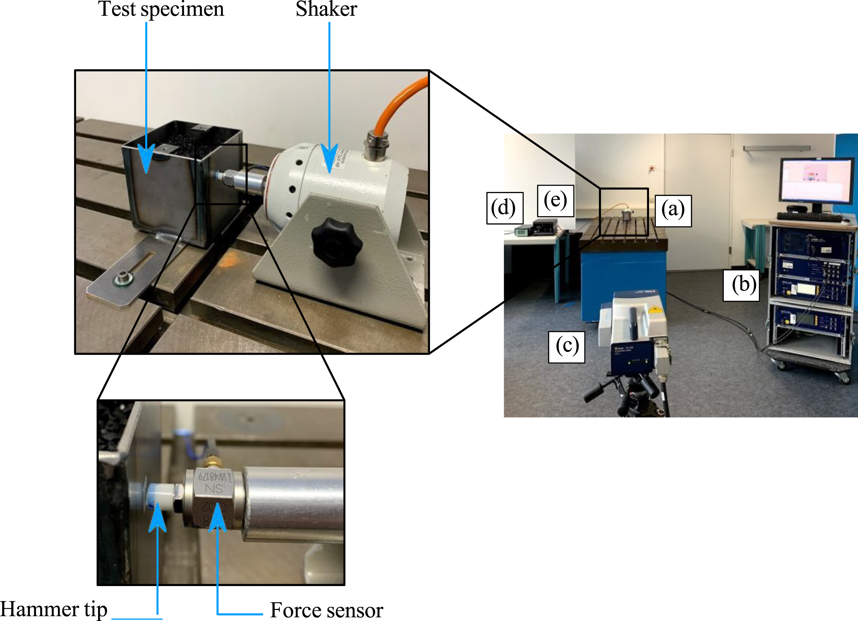
Dynamic response was measured using a Polytec PSV-400 scanning laser vibrometer. To minimize measurement uncertainties and decouple the boxes from the table, identical bolts and sliding blocks securely fastened the boxes throughout the experiment. Recognizing the influence of bolt tightening on vibration characteristics (Prasad et al., 2022b), consistent pre-load (5 Nm) was applied using a torque wrench. Furthermore, an electrodynamic shaker (TIRA) mounted with identical bolts excited the test specimen using an impulse signal to capture resonances across the desired frequency range (1 Hz–2000 Hz). Force applied to empty and partially filled boxes was measured with a PCB Piezotronics (Model 208C02) force transducer positioned between the shaker and a hard-plastic impact tip. A Bruel & Kjær amplifier (Type 2693) and a TIRA power amplifier (Type 50009) were employed for the force sensor and shaker, respectively. Selection of the optimal excitation point was achieved through an iterative process. The test specimen was excited at various locations using a modal hammer, and the resulting frequency response functions (FRFs) were visualized in real-time using Polytec software. This live spectrum analysis allowed for the identification of an excitation point that effectively excited a broad range of eigenfrequencies within the desired frequency range of interest, below 2000 Hz. Additionally, to avoid the double strokes near the test specimen, the distance between the hammer head and the test specimen is kept at approximately 2 mm. To maintain consistency, the test specimen and shaker were held in place throughout the experiment. Additionally, this experimental setup was kept fixed for the duration of the entire study to obtain a comparable frequency response. A horizontally placed scanning head of the laser scanning vibrometer captured the out-of-plane surface velocity of the specimen on a fine rectangular grid consisting of 81 measuring points defined on the measuring area (see Figure 3 (right)). In order to ensure the consistency of the measurement area, four marks are created in the shape of filled circles, making it easier to locate the scanning point in the same area even after a 20-month time interval (see Figure 3 (left)). The decision on the number of scanning points is based on an empirical study, which shows that 81 scan points are sufficient to maintain the measurement accuracy. Moreover, the frequency response of the test specimen is captured by employing an averaging technique. This entails taking six measurements at each designated measuring point, and the reported value represents the average of these measurements. Furthermore, averaging the measuring points also reduces the occurring noise effects. Marked points on the test specimen surface to define the maximum range of scan points (left) and square shape grid consisting of 81 scan points (right).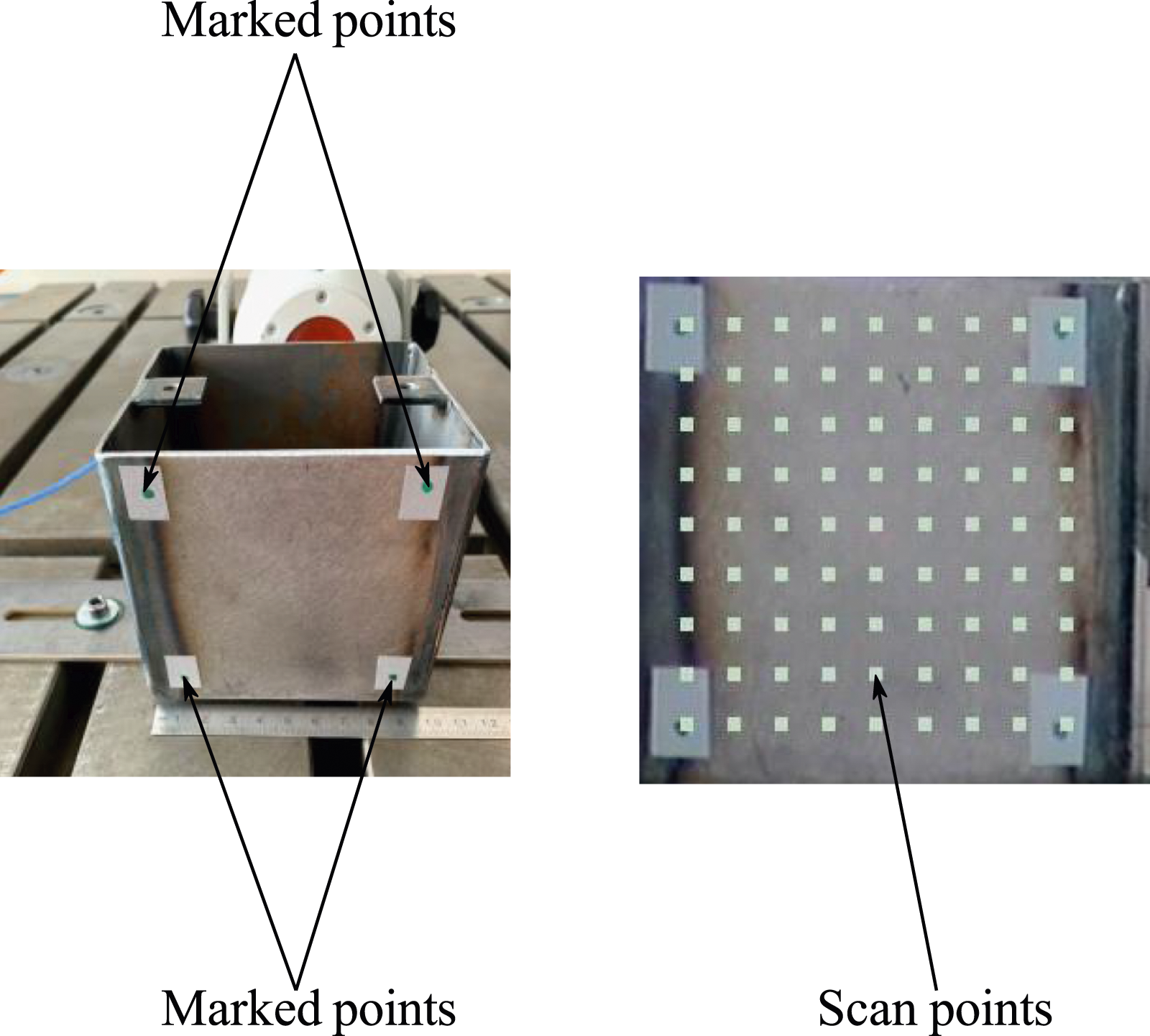
To optimize data acquisition, a parameter analysis on a reference specimen was performed. Six complex averages per point were chosen to enhance the signal-to-noise ratio. A 4 kHz low-pass filter limited bandwidth and a 12.8 kHz sampling rate with a rectangular window function provided a balance between spectral resolution and leakage (considering the periodic signal). Subsequently, measurements were conducted on empty boxes and boxes filled with granular material (40% volume). All the components of the experimental setup, including the measurement surface area on the test specimen, the placement of the bolt joint, the distance between the test specimen and the laser scanning vibrometer scan head, and all other measurement configurations, are carefully documented to facilitate the replication of the entire experimental setup after a 20-month interval. It is crucial to note that the filling material remained consistently enclosed within the boxes, which were securely sealed to prevent the material from being removed or inserted into the boxes.
2.1. Filling materials and packing ratio
The rubber granulate “RG 4.6 mm” serves as the filler material for four containers (see Figure 4). In our previous study, the damping efficiency of twenty different granular materials was experimentally investigated (Prasad et al., 2022a). The study has shown that the rubber granulate “RG 4.6 mm,” which is manufactured from discarded automotive tires, is one of the most suitable materials for particle damper design. Furthermore, its damping efficiency has been successfully validated through experimental testing on an industrial-scale wind turbine generator (Prasad et al., 2023c) and an electric drive (Prasad et al., 2024). Thus, in the present contribution, the rubber granulate “RG 4.6 mm” is chosen to investigate the influence of a long-term durability test and temperature fluctuation on its damping performance. Furthermore, for comparison purpose, sand is used as a filling material for the steel box with a PC inner layer (Box 3) (see Figure 4). Materials used for investigating damping behavior under dynamic loads.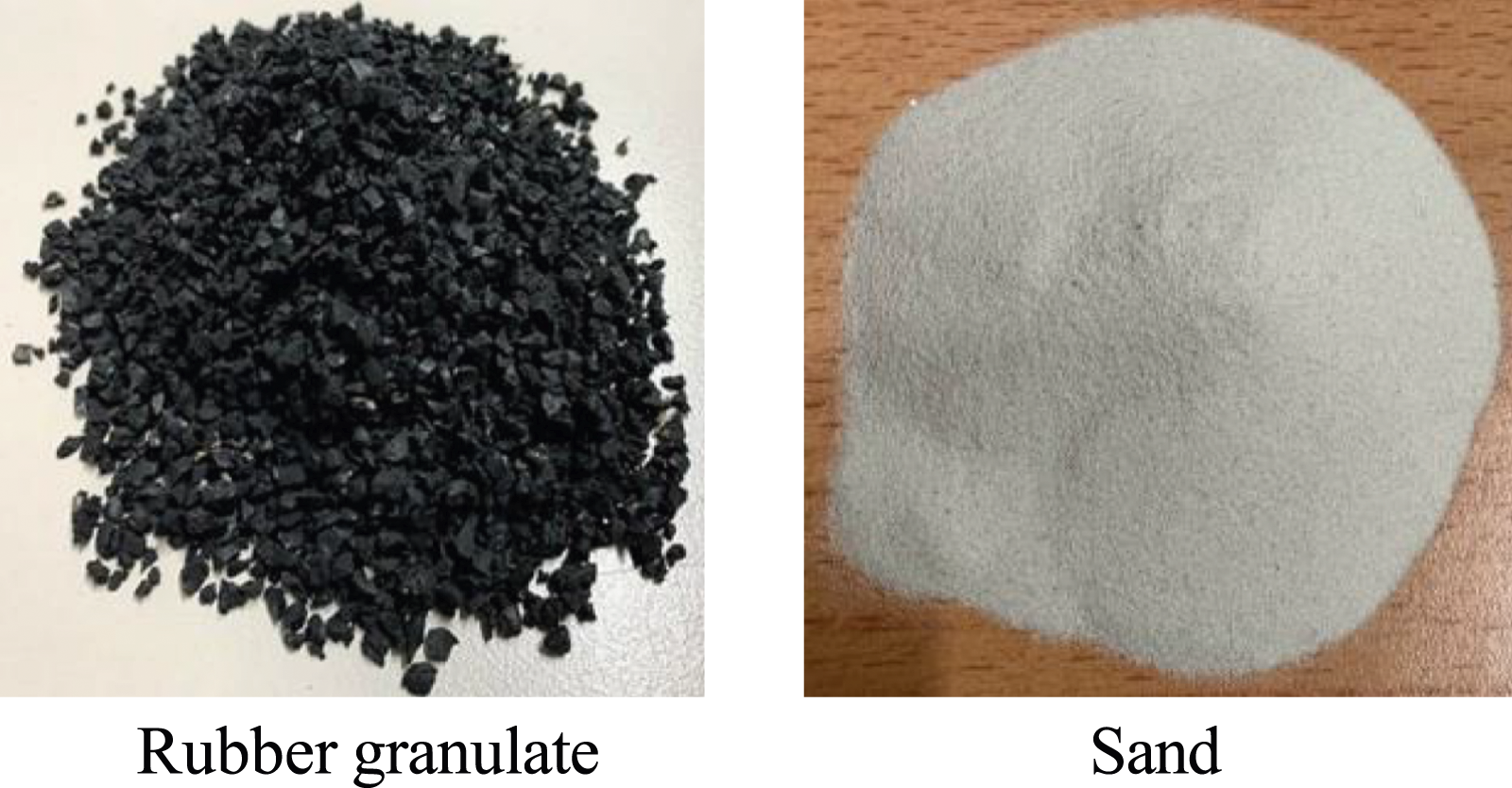
Previous research suggests an 80% filling ratio is ideal for vibration attenuation (Prasad et al., 2021). However, in this study, the primary focus is not maximizing vibration reduction but rather observing the impact of high-amplitude dynamic loads and temperature cycles on the vibration attenuation capability of the granular material. Consequently, a filling ratio of 40% was selected to induce a quantifiable decrease in vibration amplitude. This reduction serves as a metric to evaluate potential changes in the material’s vibration attenuation capability following exposure to high-amplitude dynamic loads and thermal cycling. Moreover, employing a 40% filling ratio within the boxes will introduce a strategically designed spacing. This increased void fraction (the volume of empty space within the container) is anticipated to increase random interactions between the particles and the container walls. This effect is particularly significant when the system is subjected to dynamic loads during operation on the vibrating table. This study investigates the impact of wear, induced by increased relative particle motion, on the vibration attenuation capability of the chosen granular material. While wear is not directly measured here, the possibility of accelerated wear due to increased particle–particle and particle–wall interactions within the larger void spaces is acknowledged.
2.3. Long-term durability test conditions
Box 1 experienced a cyclic load of 85 million, while Box 2 was subjected to a 165 million cyclic load. The remaining three boxes were exposed to a cyclic load of 330 million each. It is crucial to mention that two PC layers have been attached to the inner surface of Box 3. It is worth noting that before being subjected to a high-impact dynamic load, Box 5 experienced a cyclic temperature load ranging from 30°C to 120°C (see Figure 5). Table 1 provides an overview of the load cycles encountered by each container, the specific filling material used for each container, and whether the granular material underwent tempering or not. Cyclic temperature load over time. Overview of boxes, filling materials, load cycles, and tempering status.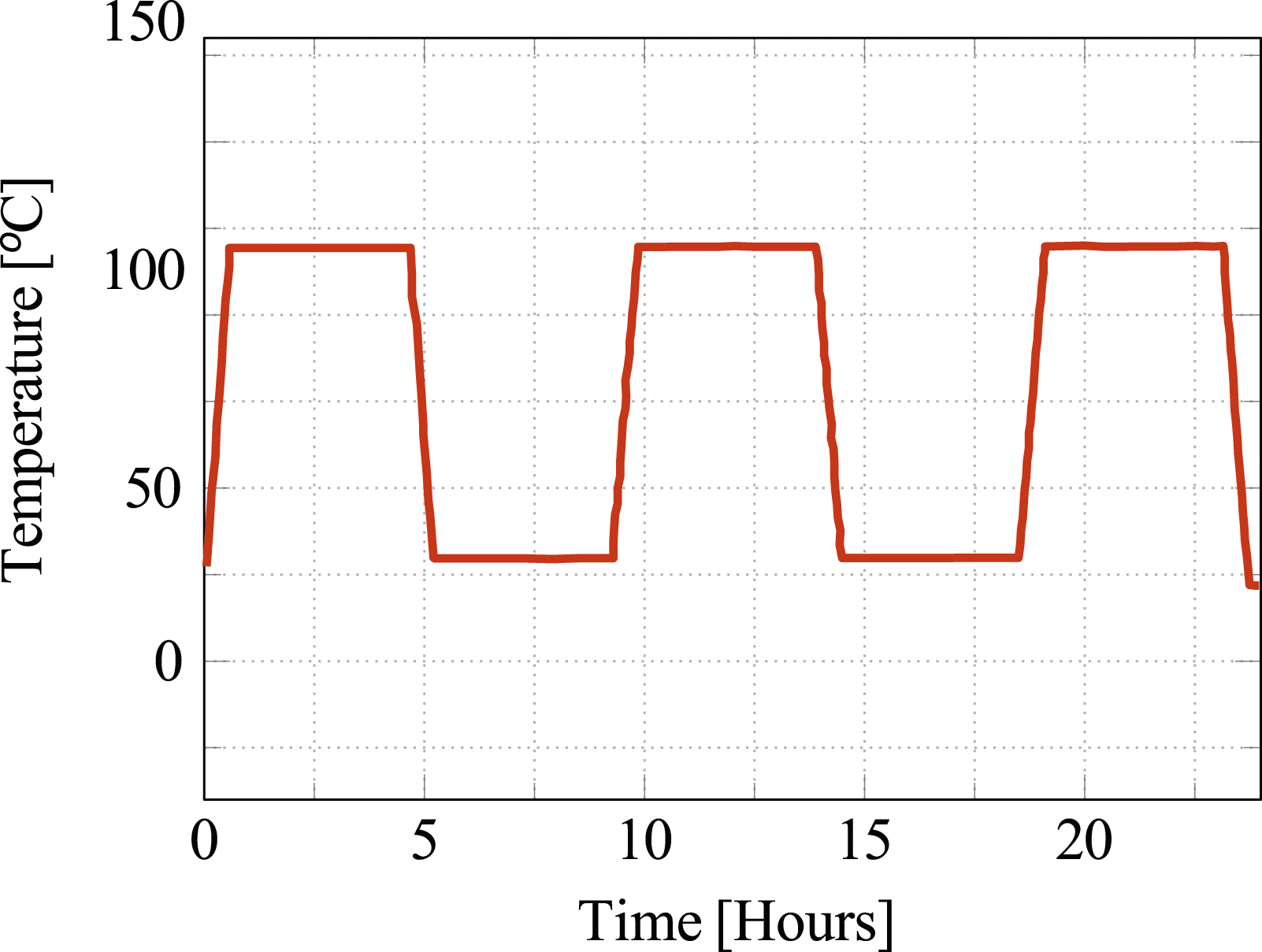
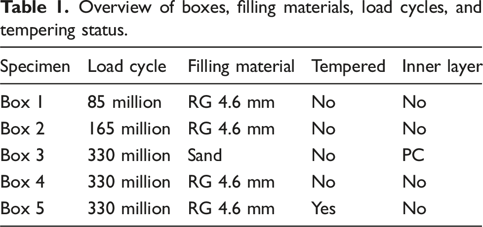
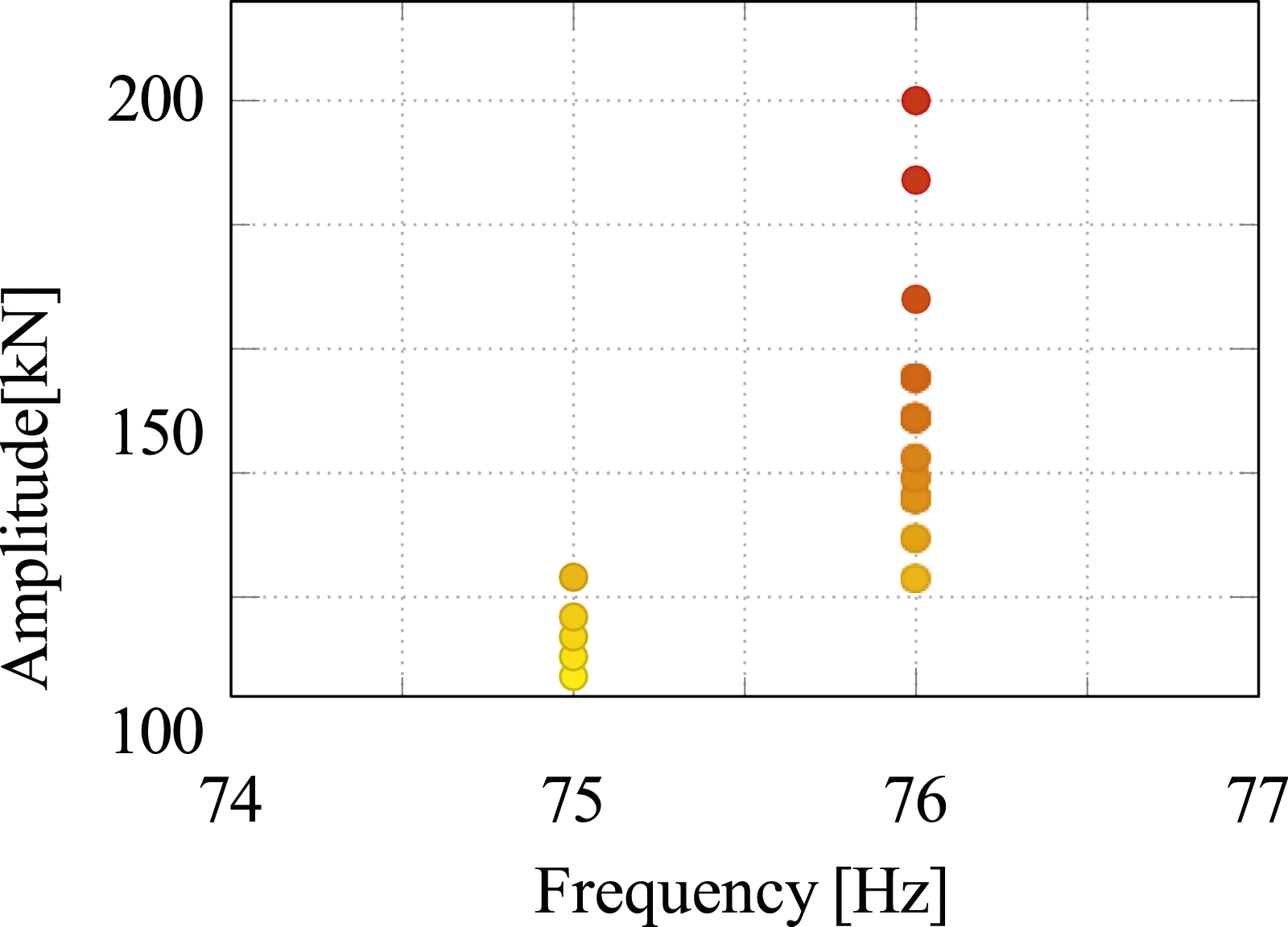
Furthermore, it is important to highlight that the long-term durability test involves a load frequency ranging from 58 Hz to 76 Hz, with the amplitude value varying in accordance with the frequency (see Figures 6 and 7). To enhance clarity and illustrate the application of various amplitude values across different load frequencies, the entire plot has been divided into two separate figures. It is noteworthy to mention that the amplitude of the applied load increases with the frequency value. As an example, a minimum amplitude load, that is, 10.7 kN, was applied at 48 Hz. In contrast, at 54 Hz and 55 Hz, varying loads with three and four different amplitude values, respectively, were imposed on all the partially filled boxes. At 75 Hz, the load amplitude ranges from 84 kN to 104 kN. The minimum load applied to the boxes at 76 Hz is 104 kN, while the maximum load at this frequency is 200 kN. In total, loads with 10 different amplitude values were applied at this frequency (see Figure 7). Variation of amplitude values and load frequencies for partially filled boxes. Variation of amplitude values and load frequencies for partially filled boxes.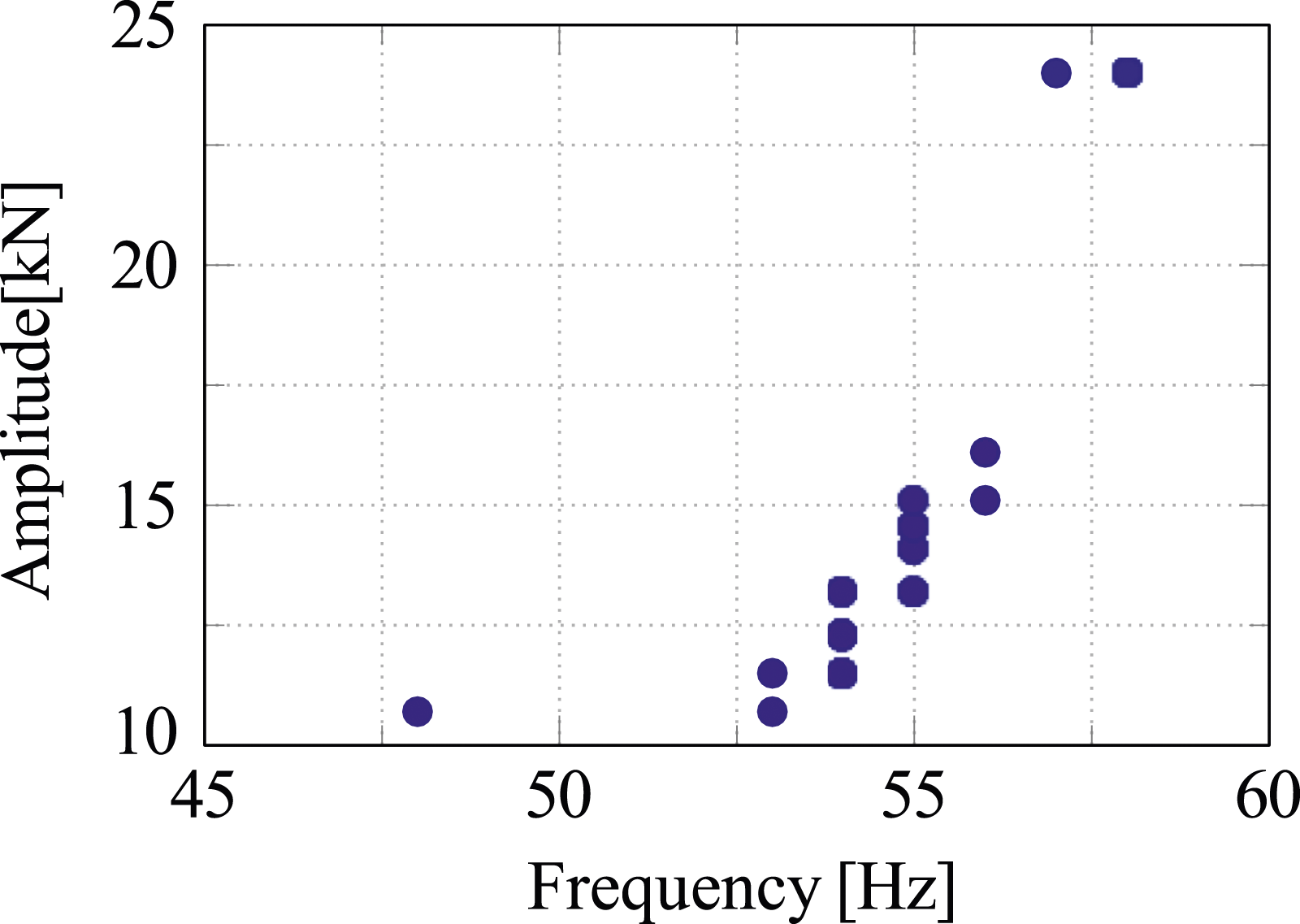
In our previous work, we successfully applied rubber granulate “RG 4.6 mm” in a real-scale wind turbine generator (Prasad et al., 2023a). Following this success, a long-term durability test has been designed to evaluate its vibration attenuation capability throughout the typical design life of wind turbine components. The selection of load frequency and amplitude for this test has been meticulously chosen based on proprietary knowledge and industry best practices held by our collaborating industrial partner, ensuring its effectiveness. While specific details cannot be disclosed due to confidentiality agreements, rest assured that these parameters rigorously evaluate the rubber granulate long-term performance within the relevant operating range of wind turbine components.
2.4. Comprehensive workflow
The experimental investigation of the influence of long-term durability on the effectiveness of particle dampers involved three distinct stages, as illustrated in Figure 8. Experimental workflow steps: Step I: measurement of the frequency response of granular materials before being exposed to a dynamic load, Step II: partially filled container exposed to intense cyclic load, and Step III: re-measurement of the frequency response of granular materials exposed to a cyclic load.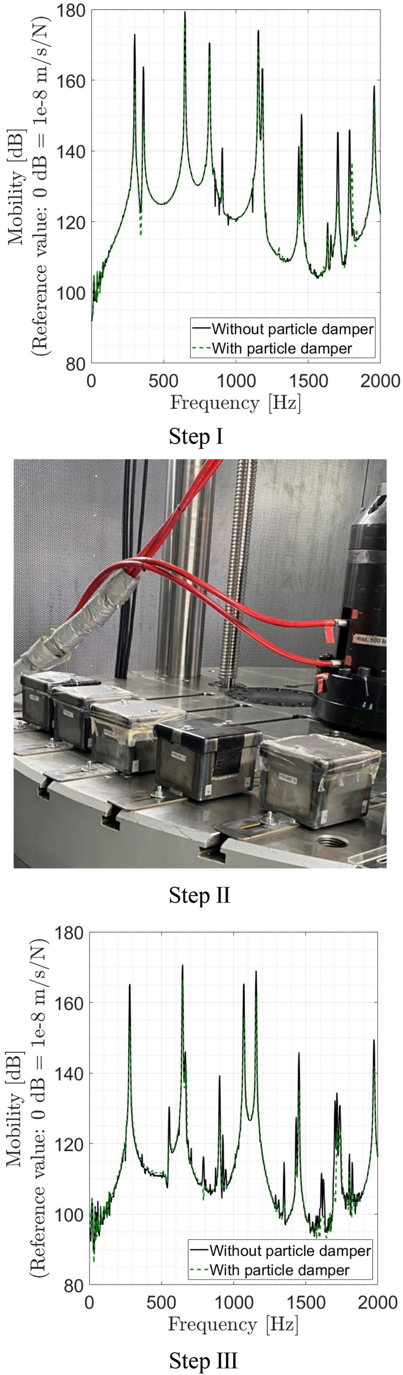
In the initial stage of the study, that is, at step I, the dynamic responses of both empty (black solid lines) and partially filled (green dashed line) test specimens are measured. The vibration attenuation observed in this measurement serves as the reference value for vibration reduction, representing the mitigation in vibration amplitude attributed to a particle damper that hasn’t experienced cyclic loading at this stage. In the second step, these partially filled containers were mounted to a vibrating table where they were exposed to higher amplitude cyclic loads for several months. In the last phase, which is step III, the vibration responses of both empty and partially filled containers were once more measured. This evaluation aimed to determine any alterations in the vibration properties of the granular materials that might have occurred as a consequence of their exposure to high-intensity dynamic loads.
3. Results and discussion
The FRFs for all boxes (empty and filled) are plotted within the 20–2000 Hz range to identify resonance peaks and evaluate vibration attenuation. Figure 9 presents a narrow-band spectrum and surface velocities of Box 1 (empty), which are centered around the normal direction of measurement. Surface velocity of Box 1 without granular material centered around the normal direction of measurement.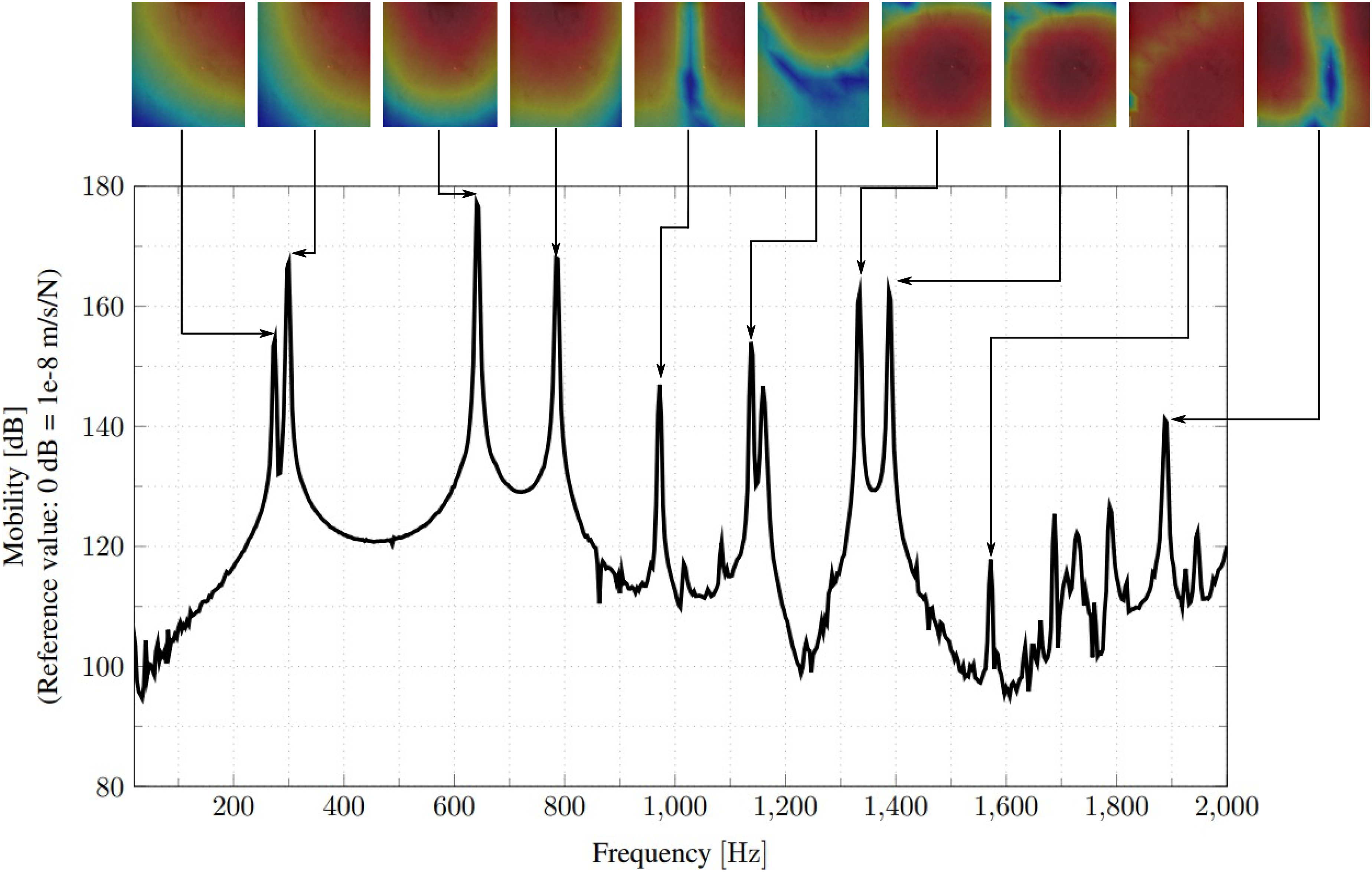
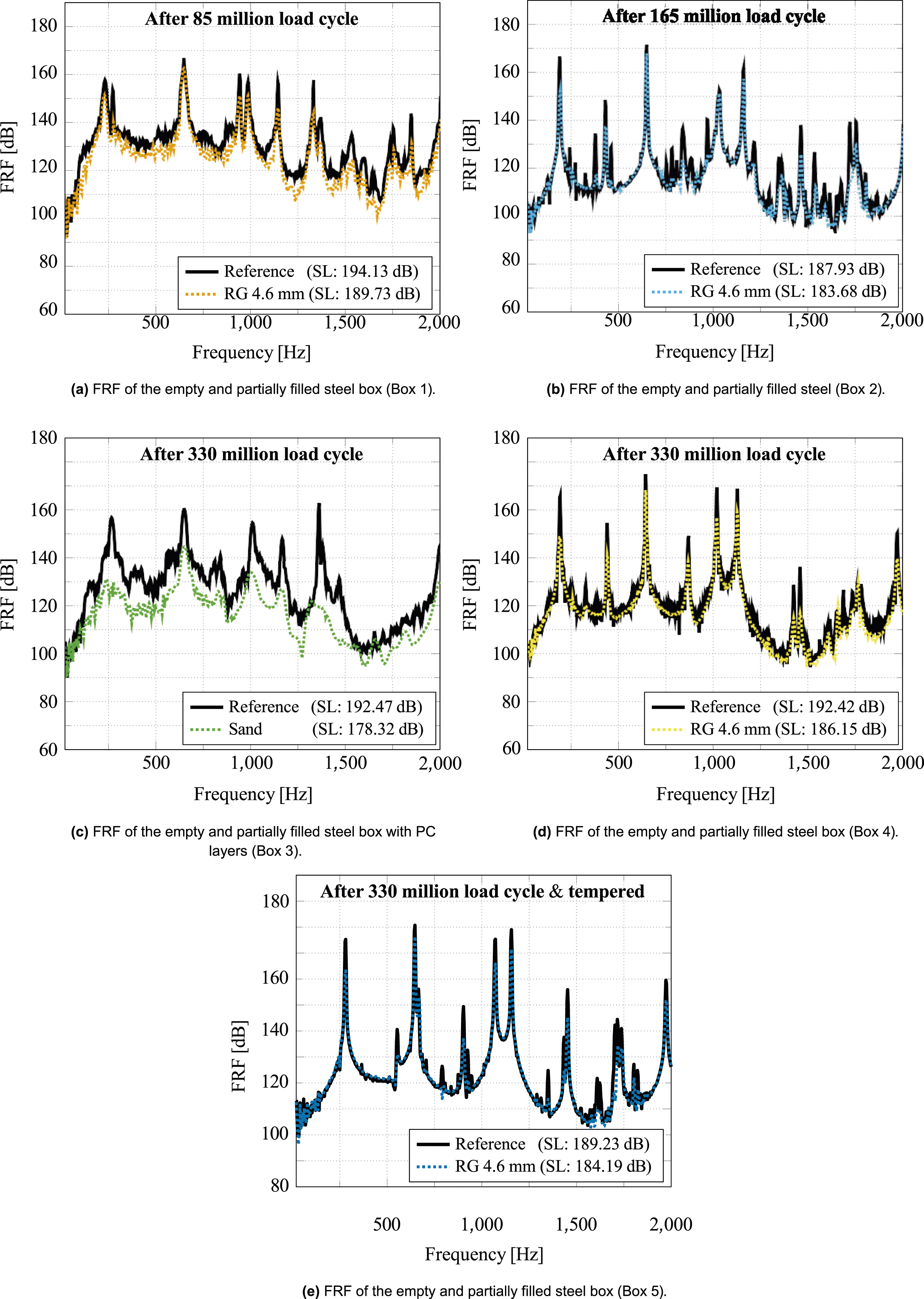
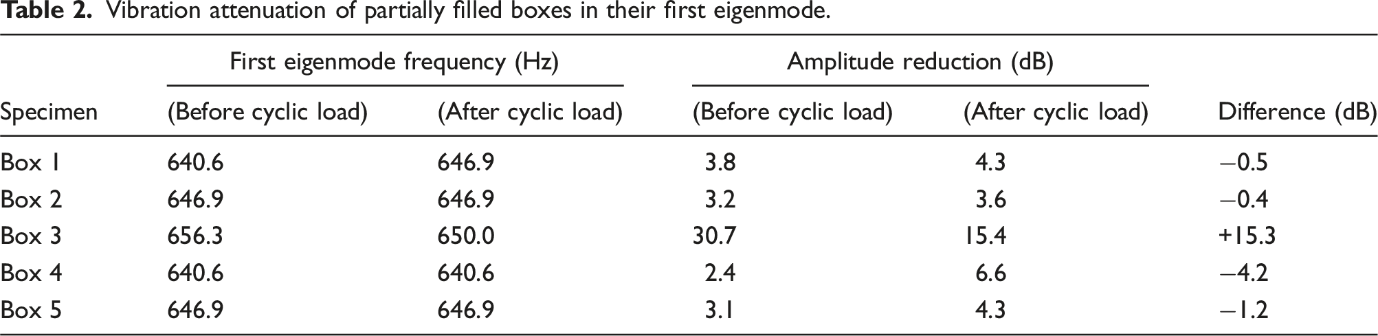
The FRF for empty and partially filled boxes before any dynamic and cyclic temperature loads shows a significant reduction in vibration amplitude, as expected due to the presence of granular materials (see Figure 10(a)–(e)). After 20 months, dynamic responses were reevaluated post high-intensity dynamic loading, as illustrated in Figure 11(a)–(e). As mentioned above, the current contribution investigates any potential changes in the vibration properties of granular materials due to dynamic loading and temperature fluctuations. Therefore, similar experimental setups were used to obtain FRFs for the test specimens before and after a 20-month exposure cycle. While Figures 10 and 11 show variations in the FRF spectra, these are likely due to minor, unavoidable discrepancies in replicating the experimental setup after a long period. These discrepancies may manifest as frequency shifts, changes in the number of resonances (20 Hz–2000 Hz), or variations in amplitude. However, such variations do not affect the assessment of vibration attenuation capabilities, as the primary analysis compares partially filled boxes with their empty counterparts. Nevertheless, conducting a comparable analysis for vibration amplitude reduction for each peak value in partially filled boxes before and after experiencing cyclic loads is not feasible due to the modified number of resonance frequencies. Therefore, the comparison of vibration reduction can be achieved by comparing the first bending mode of the box walls in each scenario, which also corresponds to the highest peak in the entire spectrum (see Figure 9). Table 2 provides an overview of the reduction in vibration amplitude observed in the first eigenmode of partially filled boxes. For instance, in the absence of any dynamic loads, Box 1 exhibits a first bending mode at approximately 640 Hz. In this particular case, the use of rubber granulate “RG 4.6 mm” can lead to a vibration attenuation of 3.8 dB, as shown in Figure 10(a) and Table 2. However, when subjected to a dynamic load of 85 million cycles, Box 1 with the same rubber granulate can achieve a vibration reduction of up to 4.3 dB in its first eigenmode (646.9 Hz), as shown in Figure 11(a). A damping performance almost identical to this has been observed for Box 2, which underwent 165 million load cycles (see Figures 10(b), 11(b), and Table 2). Furthermore, the rubber granulate “RG 4.6 mm” enclosed in Box 4 demonstrates substantial vibration reduction even after enduring 330 million load cycles. It has been noticed that prior to enduring cyclic loading, the partially filled box (Box 4) can reduce vibration amplitudes by up to 2.4 dB around the resonance frequency of 640.6 Hz. Nevertheless, following exposure to 330 million cyclic loads, the damping performance of Box 4 significantly improves, reducing vibration amplitudes by 6.6 dB around the resonance frequency of 640.6 Hz. As previously explained, the rubber granulate contained within Box 5 underwent a cyclic temperature load, spanning from 30°C to 120°C, prior to being exposed to a high-impact dynamic load. In this specific case, when the rubber granulate has been tempered and subjected to 330 million cyclic loads, the vibration attenuation following these cycles is 1.2 dB higher in comparison to the rubber granulate prior to any exposure to temperature fluctuations and cyclic loading. Moreover, it has been observed that the sand within Box 3 could reduce the vibration amplitude by 30.7 dB around the resonance frequency of 650 Hz before getting exposure to cyclic load. However, following exposure to 330 million cycles of loading, the damping effectiveness of the sand notably diminishes around the resonance frequency of 650 Hz. Hence, it can be concluded that the rubber granulate “RG 4.6 mm,” irrespective of load and temperature cycles, shows no negative effect on its damping effectiveness around its first resonance frequency. However, the damping capability of sand reduces after being exposed to cyclic loads around its first eigenfrequency. FRF of the empty and partially filled boxes before being subjected to dynamic and cyclic temperature loads: (a) FRF of the empty and partially filled steel box (Box 1), (b) FRF of the empty and partially filled steel box (Box 2), (c) FRF of the empty and partially filled steel box with PC layers (Box 3), (d) FRF of the empty and partially filled steel box (Box 4), and (e) FRF of the empty and partially filled steel box (Box 5). FRF of the empty and partially filled boxes after being subjected to dynamic and cyclic temperature loads: (a) FRF of the empty and partially filled steel box (Box 1), (b) FRF of the empty and partially filled steel (Box 2), (c) FRF of the empty and partially filled steel box with PC layers (Box 3), (d) FRF of the empty and partially filled steel box (Box 4), and (e) FRF of the empty and partially filled steel box (Box 5). Vibration attenuation of partially filled boxes in their first eigenmode.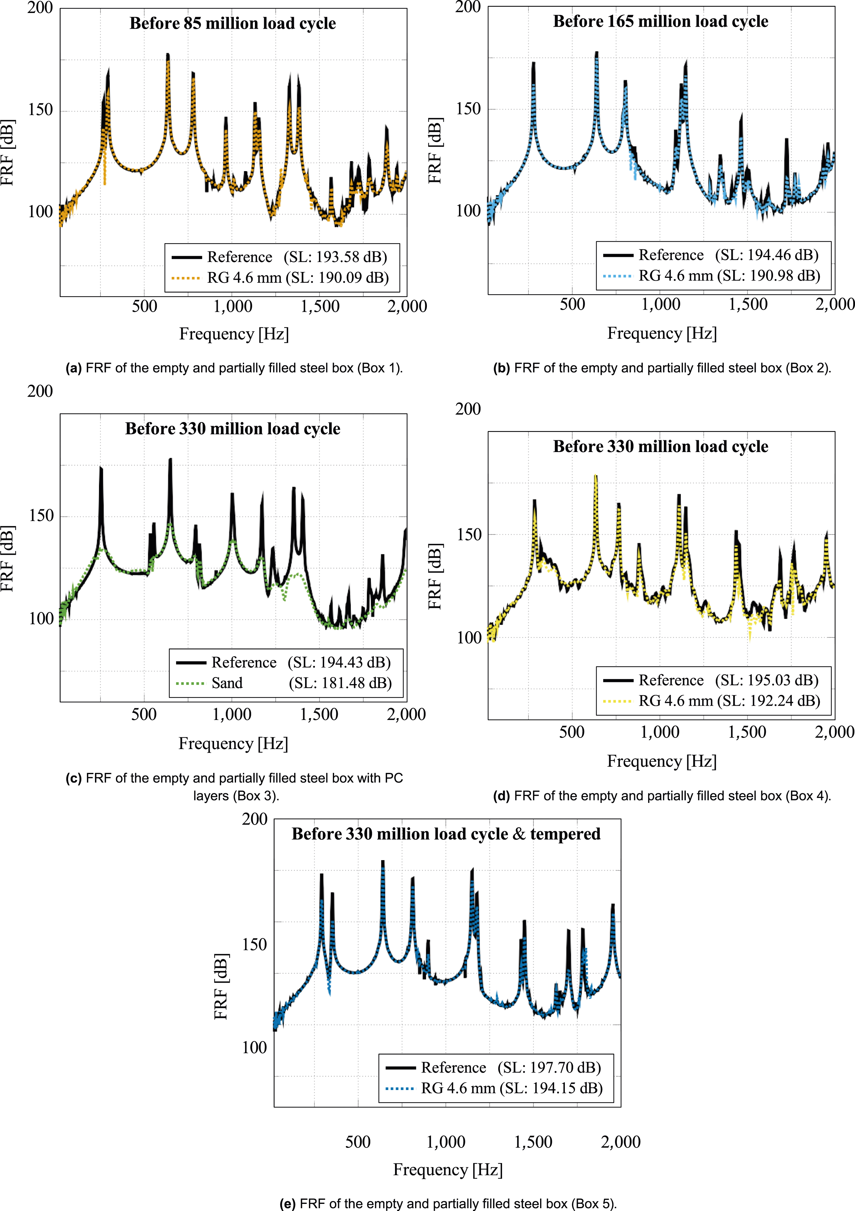
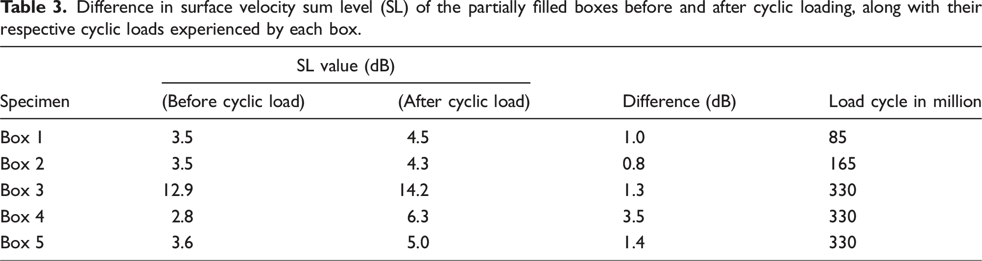
Difference in surface velocity sum level (SL) of the partially filled boxes before and after cyclic loading, along with their respective cyclic loads experienced by each box.
From the above discussion, it can be concluded that the damping characteristics of the rubber granulate “RG 4.6 mm” remain relatively constant around its first resonance frequency both before and after being subjected to 85 and 165 million cyclic loads. Additionally, the overall damping performance of the “RG 4.6 mm” in the frequency range of 20 Hz to 2000 Hz also remains consistent even after exposure to cyclic loads of 85 million and 165 million. Therefore, it can be assumed that the damping performance of the rubber granulate “RG 4.6 mm” remains unaffected by a small number of cyclic loads. However, a significant improvement is observed in both the overall damping performance of “RG 4.6 mm” and around the first resonance frequency after being subjected to cyclic loads of 330 million. The reason behind this could be the wear occurring in the rubber granulate, which leads to an increase in the span of rubber particle size distribution. This increase results in a greater number of particles and raises the possibility of particle–particle and particle–wall collisions, which is one of the major damping mechanisms for particle dampers. Furthermore, wear can also increase the particle size distribution span, which is a contributing factor to the increased damping capability of the rubber granulate enclosed in Box 4. In our previous work, it has also been shown that rubber granulate with a wider particle size distribution is more effective in reducing the vibration amplitude of a structure (Prasad et al., 2022b). The frequency distribution curve of all nine granular materials used in Prasad et al. (2022a) is given in Figure 12, in which rubber granulates “RG 4.6 mm” (solid blue line) and “RG 6.4 mm” (solid red line) exhibit a wider particle size distribution, and hence, they have also shown tremendous Damping capability. It is crucial to mention that an escalation in the number of load cycles may lead to a deterioration in the vibration attenuation capability of the rubber granulate. To investigate this, further study is required. However, the employed load frequency, amplitude, and number of load cycles in this study are indicative of the life cycle of wind turbine components. In this context, the rubber granulate “RG 4.6 mm” emerges as an optimal selection for designing particle dampers. Nevertheless, it should be ensured that wear does not transform the rubber granulate into a powder form. In our previous work, it has been observed that the damping efficiency of rubber powder is significantly lower compared to rubber granulates (Prasad et al., 2022b). Volume-based relative frequency distribution of rubber granulates.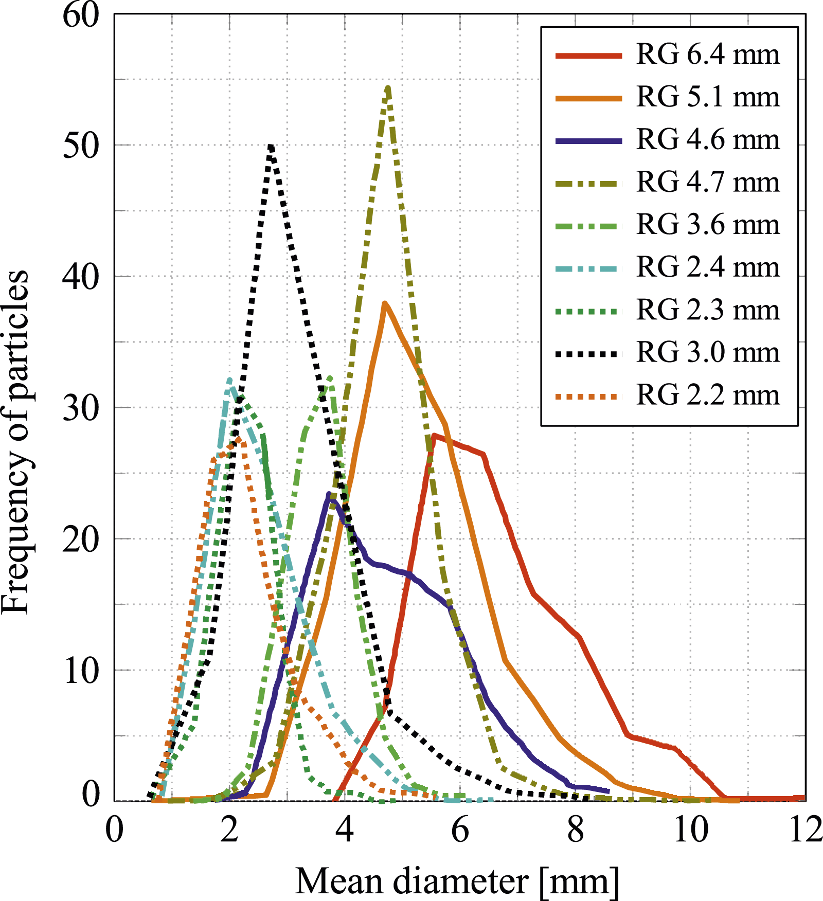
Furthermore, a noticeable enhancement in the damping performance of “RG 4.6 mm” has been also observed following exposure to 330 million cyclic loads and temperature fluctuations (Box 5). Nevertheless, in this instance, it is evident that the damping performance of Box 5 is influenced by the high-temperature cycle load when compared to Box 4. However, no negative effect on the damping performance has been observed for the rubber granulate enclosed in Box 5 after exposure to temperature fluctuations and cyclic loads. Hence, it can be concluded that the damping performance of the rubber granulate “RG 4.6 mm” remains unaffected by cyclic load, temperature fluctuation, and wear. Still, to confirm whether wear has occurred in rubber granulate particles, particle measurement studies before and after the cyclic load need to be carried out. Moreover, to investigate the influence of temperature on vibration attenuation properties, a dedicated experiment is necessary. This experiment would involve measuring the response of rubber granulate to vibrations before and after exposure to elevated temperatures. It is important to note that this evaluation would exclude high-amplitude cyclic loading, which falls outside the scope of this work. Thus, based on the discussion, it can be assumed that the rubber granulate “RG 4.6 mm” could be an optimal option for designing particle dampers. It offers the ability to withstand negative effects caused by cyclic loading and temperature fluctuations, in addition to other positive factors already discussed in our previous work (Prasad et al., 2022a).
4. Summary and outlook
This study assessed the impact of dynamic and cyclic temperature loads on particle damper performance using five steel boxes filled with rubber granulate “RG 4.6 mm” and sand. Dynamic response measurements were taken on partially filled boxes before and after exposure to increasing levels of cyclic loading (up to 330 million cycles) and high-amplitude dynamic loads. Additionally, Box 5 experienced thermal cycling 30 o C to 120 o C before vibration testing. Final vibration measurements on both empty and partially filled boxes allowed for the evaluation of any alterations in the vibration characteristics of granular materials resulting from exposure to high-intensity dynamic loads. It has been observed that the rubber granulate “RG 4.6 mm” exhibited unchanged vibration reduction at 85 and 165 million cycles but showed increased vibration attenuation at 330 million cycles. This suggests wear-induced changes in the particle distribution, potentially leading to a wider range and improved vibration mitigation capability, as observed in our prior work (Prasad et al. (2022b). However, conducting a further experimental study is necessary to verify changes in the particle size distribution of rubber granulate before and after cyclic loading, indicating the presence of wear. Furthermore, it has also been observed that cyclic temperature load can affect the damping capability of a particle damper. Nevertheless, no negative effect has been observed due to temperature fluctuation on rubber granulate before and after being subjected to cyclic load. Hence, rubber granulate “RG 4.6 mm” proves to be an optimal choice for designing particle dampers, offering advantages in terms of vibration reduction capability, reduction in additional mass, and resilience to negative effects from cyclic loading and temperature fluctuation. Sand can also be a good choice for particle damper design, exhibiting positive effects on overall vibration mitigation performance after being subjected to cyclic loads. However, their additional mass and influence on humidity can be obstacles to their use in real-world applications (Prasad et al. (2022a). While results offer valuable insights, isolating the temperature effect remains a limitation. The combined influence of temperature cycling, cyclic loading, and high-impact loads hinders definitive assessment. To isolate temperature’s role, future experiments with controlled temperature exposure and vibration response measurements are recommended. This would exclude high-amplitude cyclic loading, providing a clearer understanding of temperature’s impact. This knowledge would significantly benefit the design of rubber granulate particle dampers for temperature-critical applications.
Footnotes
Declaration of conflicting interests
The author(s) declared no potential conflicts of interest with respect to the research, authorship, and/or publication of this article.
Funding
The author(s) disclosed receipt of the following financial support for the research, authorship, and/or publication of this article: This work was supported by the German Federal Ministry for Economic Affairs and Climate Action (BMWK) under grant FKZ 03EE2008E.