
Abstract
This study proposes a novel semi-active vibration control technique for mechanical transmission systems. The backbone of current research technology is the adaptive stiffness and damping properties of metal rubber (MR) which plays the role of tuning to the vibrational system eigenmodes. The adaptive properties of MR material were proved by a previous study, but the present research investigates the effect of this feature on the structural response and designs an MR-based semi-active vibration controller for industrial application. For this purpose, the semi-active control strategy is created based on an optimal tuning using experimental harmonic test results. The control strategy is applied in practice using a linear actuator controlled by a double pole double throw (DPDT) relay, and National Instruments hardware and software for reading data and writing the control task. The isolator attachment position is defined through the analysis of eigenmode shapes that are predetermined by numerical simulation. A maximum isolation rate of 55.17% is measured near the vibration isolator position. It is observed that the isolation position has a prominent effect on structure vibration behavior where the elastic wave has been reduced in amplitude by passing the isolator position. The effectiveness of the MR-based semi-active control approach is eminent and its application for vibration isolation of commercial mechanical transmission systems could be studied in the future.
1. Introduction
Vibration propagation in mechanical transmission systems has critical environment impacts (Pan and Chen, 2003). In this regard, vibration control approaches of three well-known techniques, passive (Ishida, 2012), active (Li et al., 2023), and semi-active (Frey et al., 2013; Guan et al., 2005), are adopted by many researchers. Semi-active control systems are a compromise between active and passive control systems because they can be adapted to changes in structural properties and dynamic loading. Due to this adaptability, they surpass passive solutions. In addition, they operate based on shifting control states. This shifting demands a momentary power supply which is clearly lower than the steady power required to supply active systems (Soong and Spencer, 2000; Sun et al., 1995).
There exists a wide range of technologies to design a semi-active vibration control, the underpinning of which is adjusting stiffness, damping, or mass to make possible the adaptability. Few examples of technologies with the potential adaptability can be mentioned as magnetorheological elastomers (Leng et al., 2022), shunted piezoelectric patches (Chatziathanasiou et al., 2022), tunable mass moment of inertia mechanism (Wrona et al., 2021), metal rubbers (MR) (Rieß and Kaal, 2021), and so on.
MRs–also called metal cushions–are lightweight porous meta-materials manufactured through metal wire winding or laying techniques (Ma et al., 2015; Xu et al., 2018; Zheng et al., 2022). The internal contact within the knitted metal mesh wires results in a high internal friction and energy dissipation. Additionally, studies have revealed that by enhancing the MR forming density, its stiffness increases, while its structural damping coefficient decreases (Rieß and Kaal, 2021).
Despite the availability of constitutive models to estimate the nonlinear static stiffness of metal cushion (Zou et al., 2021), prediction of its dynamic behavior depends on many factors particularly given that the material's complicated microstructure provides unreliable contact surfaces under various loading regimes (Ren et al., 2020). Therefore, prediction of MR performance by computation is complicated, and experimentation is of prime significance for this purpose. Uniaxial static loading test for MR have resulted a multi-zone curve including linear, soft, and rigid regions where loading beyond the soft zone is not recommended to secure stability. Compression and tension tests have shown that the Poisson's ratio of MR is roughly equal to zero. Relevant experiments have also confirmed that the material damping properties are variable with pre-compression, excitation frequency and amplitude, and dynamic strain (Wang et al., 2010). In an industrial application where a pipeline has been covered by MR material, increasing the number of layers and excitation amplitude has led to a larger damping impact (Xiao et al., 2018).
The result of a high-speed impact test, conducted by Zou et al. (2021), has revealed that most of the stress energy is reflected, a portion is consumed and less than 1% is transmitted. In contrast to certain applications, where the isolator is placed between the facility and a rigid foundation, wave transmission is a concern where the isolator is positioned between a target component and a component with larger stiffness both of which vibration is significant. Thus, the low level of stress wave transmission offered by MR material is a promising point for such applications. In an agricultural machine, a superior reduction in transmission rate of vibration is attained by MRs placed for mounting the engine bracket, and filling the gap between a vibration isolation platform and bearing surfaces (Jin et al., 2019). In a rotor drop test, placement of an MR ring between bearing outer face and the foundation support has been found effective in vibration level reduction (Yili and Yongchun, 2015).
Up to now, MR material has only been used in passive mode for vibration mitigation in industrial systems (Geng et al., 2022; Jin et al., 2019; Yili and Yongchun, 2015) due to its sophisticated dynamic performance under various environment impacts. The aim of this study is to first comprehend the influence of adaptive properties of an MR-based isolator on system dynamic response, and then employ this material to design a semi-active vibration isolator. In this regard, the current investigation is carried out in two phases. First, the adaptive properties of MR material which is proved by a previous study (Rieß and Kaal, 2021), is considered for investigation of structural dynamic response control. Second, an optimal semi-active vibration control strategy is designed and implemented to suppress the vibrations in a bearing host plate. The semi-active approach is applied in isolator mode, which means that the MR is placed between the structure and a rigid boundary. Accordingly, the minimum vibration can be achieved by affecting the structure global stiffness and damping. The semi-active control levels with certain stiffness and damping levels are acquired through compressing the MR material using a linear actuator. The sections of this paper basically follow the aforementioned research phases.
2. Materials and methods
2.1. Formulating the semi-active vibration isolation system
Dynamic transmission systems are usually protected by thin-walled shell structures. In such structures, the main eigenmodes of vibration are out-of-plane ones. To isolate out-of-plane types of vibration, normal attachment of vibration isolator to the system surface is required as shown by Figure 1. It can contribute in axial stiffness and damping properties effectively. To introduce the semi-active concept, the isolator is enhanced by MR material which offers stiffness Schematic representation of a vibration system integrated with semi-active isolator.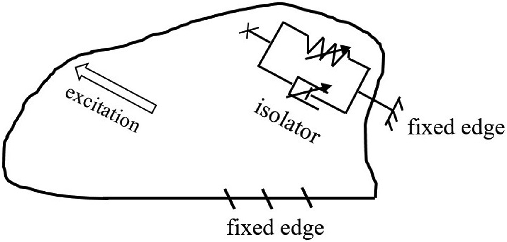


The dynamic force equilibrium equation of the structure integrated with the semi-active vibration isolator is presented by equation (3).

In this paper, the design of the semi-active control scheme discussed in section 2.3.2 is based on an optimization algorithm which uses experimental data. Two optimization algorithms are introduced in this respect as follows: (1) point-by-point optimization and (2) cumulative optimization.
By applying the point-by-point optimization, the mobility response amplitude can be minimized frequency-by-frequency. Considering the mobility function v, as the velocity divided by input force amplitude (ν=V/


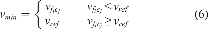
On the contrary, the cumulative optimization involves minimization of the area under the velocity-frequency response curve. Considering n frequency intervals of
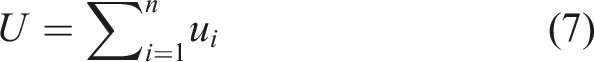
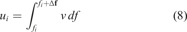
The optimization procedure is defined by equation (9): the optimal pre-compression level corresponds to the minimum of the U values which must be less than a reference value U
ref
. U
ref
is a reference value corresponding to the U function without any isolation treatment.
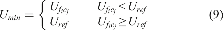
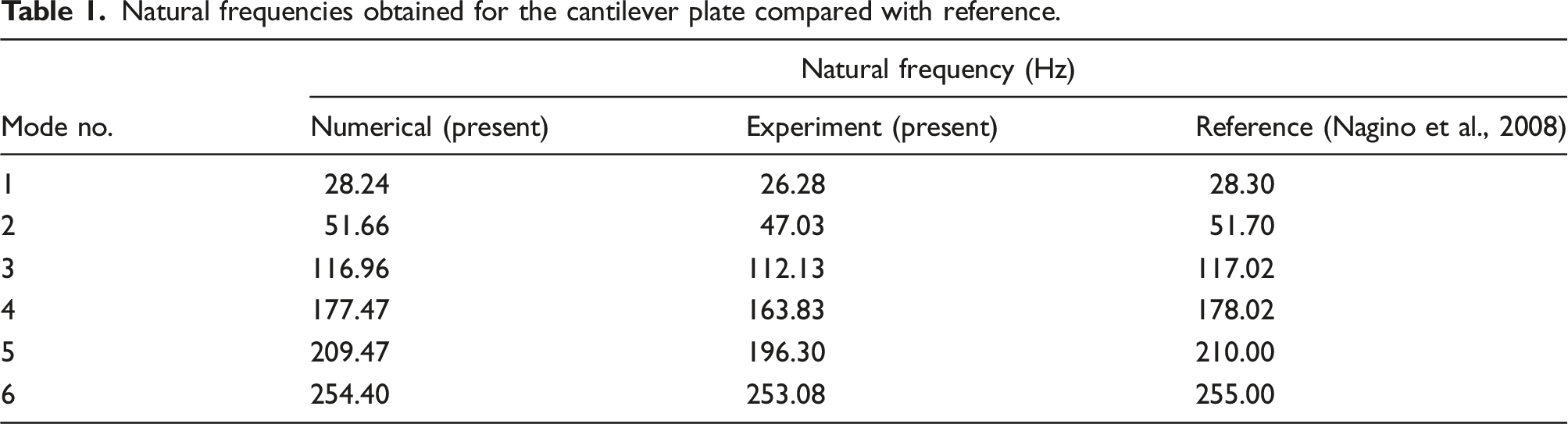
By solving the optimization problem upon each optimization strategy, the optimal control function can be derived consisting n number of frequency intervals tuned to optimum pre-compression rates C
op
. So that the semi-active control function can be expressed by equation (10).
2.2. Selection of installation and measurement point on the structure
Vibration mode shapes play a key role to position the vibration isolator properly. The maximum vibration reduction rate can be attained if the isolator can be positioned near the antinodes corresponding to a larger number of eigenmodes. Targeting a large number of eigenmodes is challenging when it comes to higher modes of vibration. In this condition, attachment of the isolator can be found effective if it is positioned close to the antinodes corresponding to eigenmodes with high effective mass. The effective mass M
eff
can be related to mode participation factor γ as provided by equation (11).

The mode participation factor can be obtained as follows

2.3. Experiment phases
Two main phases are defined to conduct experiments. The first phase aims to investigate the potential of MR rubber adaptive behavior on structural response control as explained in section 2.3.1. The second phase is designed to assess the effectiveness of an optimal semi-active control for vibration isolation of a bearing host plate explained in section 2.3.2.
2.3.1. Phase A: Cantilevered plate
To have a proper understanding of the effect of adaptive properties of MR material on structural vibration response, a steel (E=210 GPa, υ=0.3) plate with 450 mm length, 300 mm width, and 3 mmm thickness cantilevered on its length is considered for a forced vibration test. The MR is compressed by different rates using a linear actuator achieving different stiffness and damping levels. The effect of isolator on the system vibration can be determined by investigating U parameter and the shift in natural frequencies. Thus, the purpose of phase A is to gain confidence in the feasibility of adaptive structural control through an MR-based isolator.
2.3.2. Phase B: Bearing host plate
The objective of this part is to design a semi-active control scheme. In this regard, a fixed edge steel plate with 420 mm length, 270 mm width, and 3 mm thickness subjected to bearing-induced vibrations is considered. The flowchart of design procedure is given by Figure 2. The first step, parametric studies, refers to a set of experiments required to record the structure response for a range of pre-compression rates. Since in mechanical transmission systems usually a shaft is subjected both in axial and lateral directions, the parametric studies should cover this loading condition. In this regard, the excitation is applied with an angle of 45° to the shaft constrained by the bearing to guarantee equal loading components. The second step is to find the optimal pre-compression levels based on the optimization criteria. The third step is finding the optimal control function and building an automatic open-loop semi-active scheme upon that. The last step is the employment of the control scheme in vibration tests forced by an excitation in frequency range of interest to assess its effectiveness. Since the control scheme is built upon the optimization of results per 45° angle of excitation, it is conservative enough to be applied for different ratios of loading components. Studying the effectiveness of the present control scheme for different loading components is of prime importance; the experiment is described in Appendix A. Flowchart showing the necessary steps for designing the semi-active control.
2.4. Composition of the experiment setup
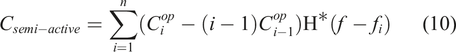
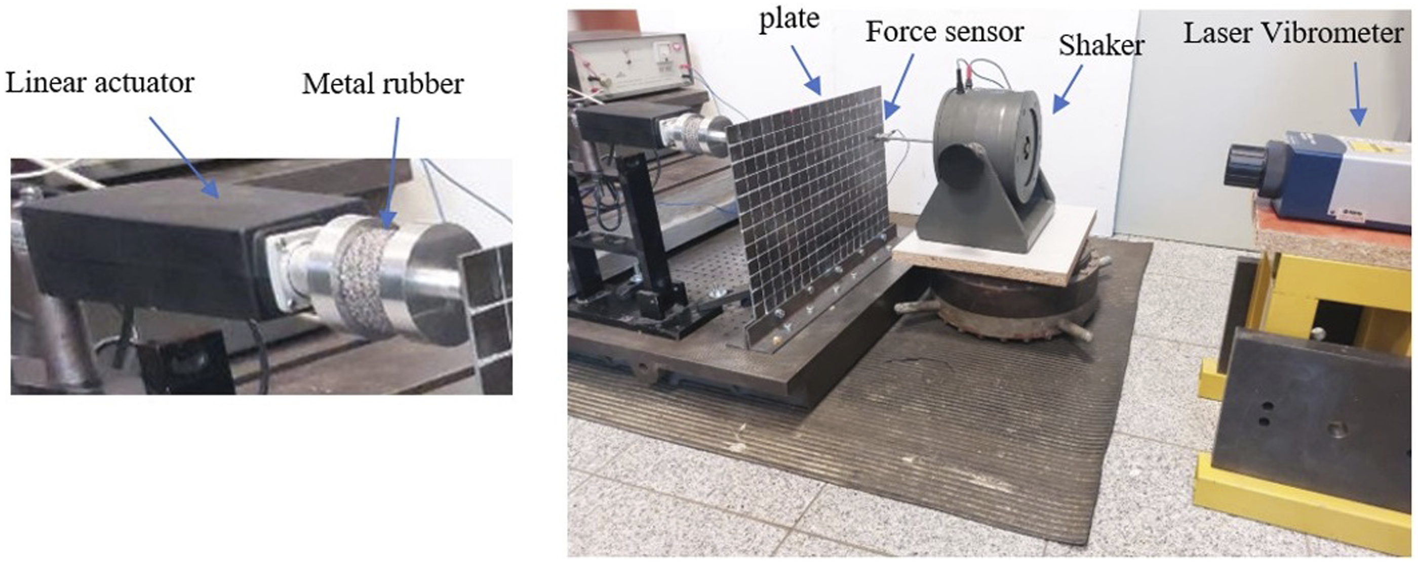
To generate vibrations, a shaker applies a sine sweep force, 25 mm and 100 mm far from the cantilevered plate free vertical and horizontal edges, respectively. The control devices include (a) measurement instruments and (b) actuation devices as depicted by Figure 3. Schematic representation of experiment setup for the automatic open-loop semi-active control.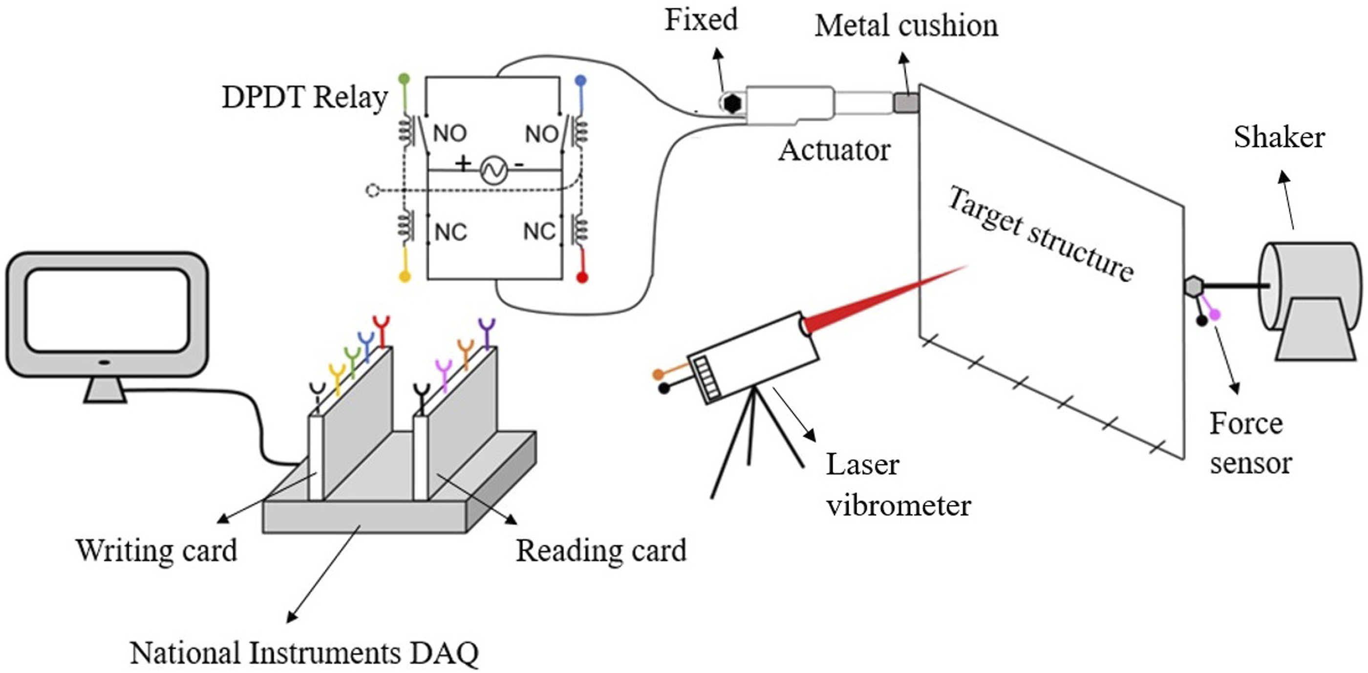
A laser vibrometer for measuring velocity, a dynamic force sensor to measure excitation force variation, and a National Instruments (NI) reading card for recording and collecting data are required for measurement.
An MR sample, a linear actuator, a DPDT relay supplied by a power source, and an NI writing card are necessary for actuation tasks. The actuator embedded with a hall sensor is dedicated to control the compression rate of metal rubber (Silentflex ref. no.: 990000H27E) to change the control state and achieve different stiffness and damping levels. To control the actuator motion, a DPDT relay is employed which can change the polarity and create three states of extension, contraction, and stop. To generate motion steps, the hall sensor measures the piston position and attains the ideal position through a feedback control program. All reading and writing tasks are programmed in LabVIEW (version 2011; National Instruments) program.
3. Results and discussion
3.1. Results of Phase A (cantilevered plate)
Natural frequencies obtained for the cantilever plate compared with reference.
Vibration test setup of the cantilevered plate controlled by the MR-based isolator.
The vibration level averaged along the free edge for four levels of pre-compression (C) corresponding to 1 mm, 2 mm, 3 mm, and 4 mm displacement of actuator piston is presented in Figure 5. It can be inferred that the MR-based isolator is tunable to the eigenmodes within the studied frequency range. The isolator influences the response by changing both the amplitude level and number of resonances. The large amplitudes which belong to resonances are all diminished under the present isolation technique except the first one which shows a deteriorative effect for pre-compression rates of 0.76% and 1.95%. The number of resonances with isolation is obviously larger than the without isolation case due to absorption of energy. Vibration levels for different pre-compression rates obtained by harmonic test.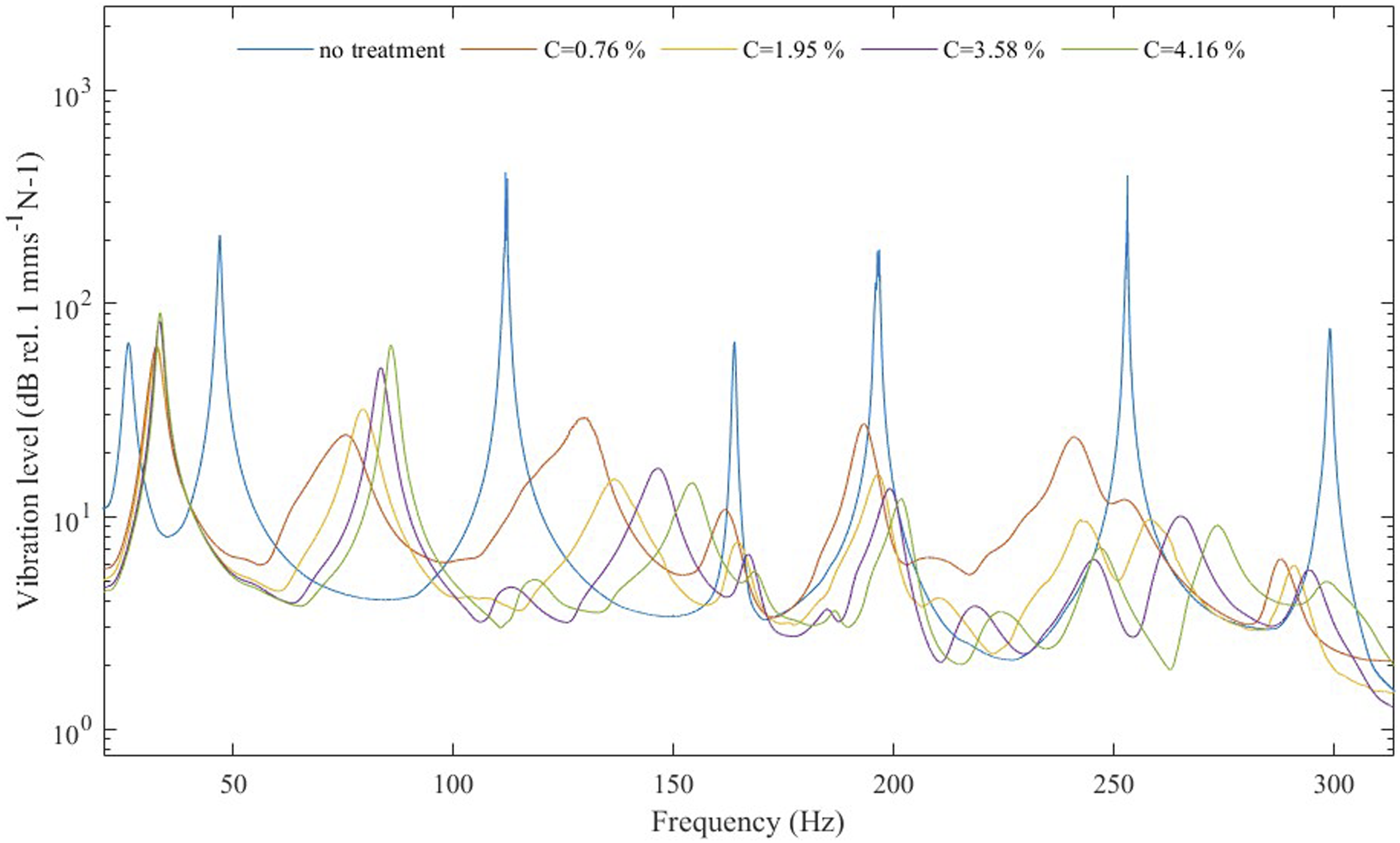
The reduction rate achieved per different pre-compression rates.
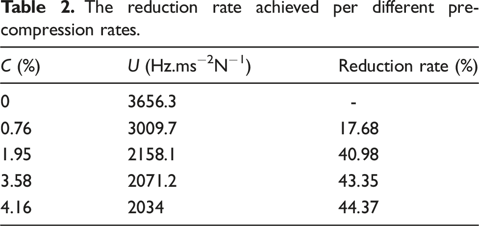
The results revealed that higher pre-compression rate offers higher isolation rate over the whole frequency range, although the relationship between the C parameter and vibration amplitude is not necessarily linear when it comes to local peaks. So that the isolation rate can be improved if the isolator follows a semi-active scheme optimized in frequency domain. Accordingly, an automatic semi-active vibration control strategy will be proposed in the next section, where wide-band vibration cancellation is accomplished through a range-by-range vibration treatment.
3.2. Results of Phase B (bearing host plate)
The bearing host plate, which is fixed over the edges, is excited by a shaker in the frequency range of 200 Hz–1800 Hz as shown by Figure 6(a). As described in Section 2.3.2, the excitation is applied with an angle of 45° to ensure equal loading components are applied. The frequency response derived from experiment is used to extract natural frequencies. Moreover, a free vibration analysis is carried out through numerical simulation using higher order shell elements for the plate, and a point mass element for representing the bearing and shaft masses as shown by Figure 6(b). Bearing host plate: (a) schematic model and (b) finite element model.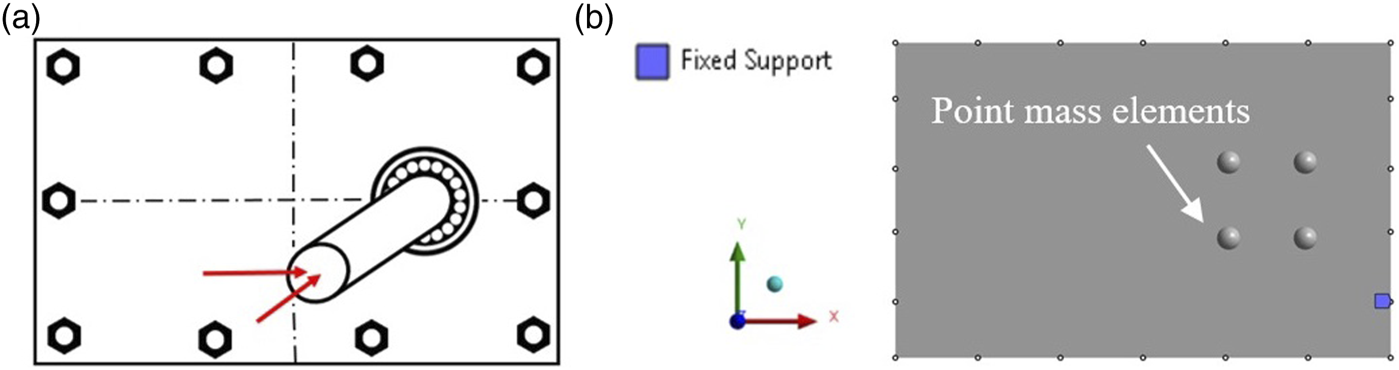
Natural frequencies for the bearing host plate (420*270*3 mm3).
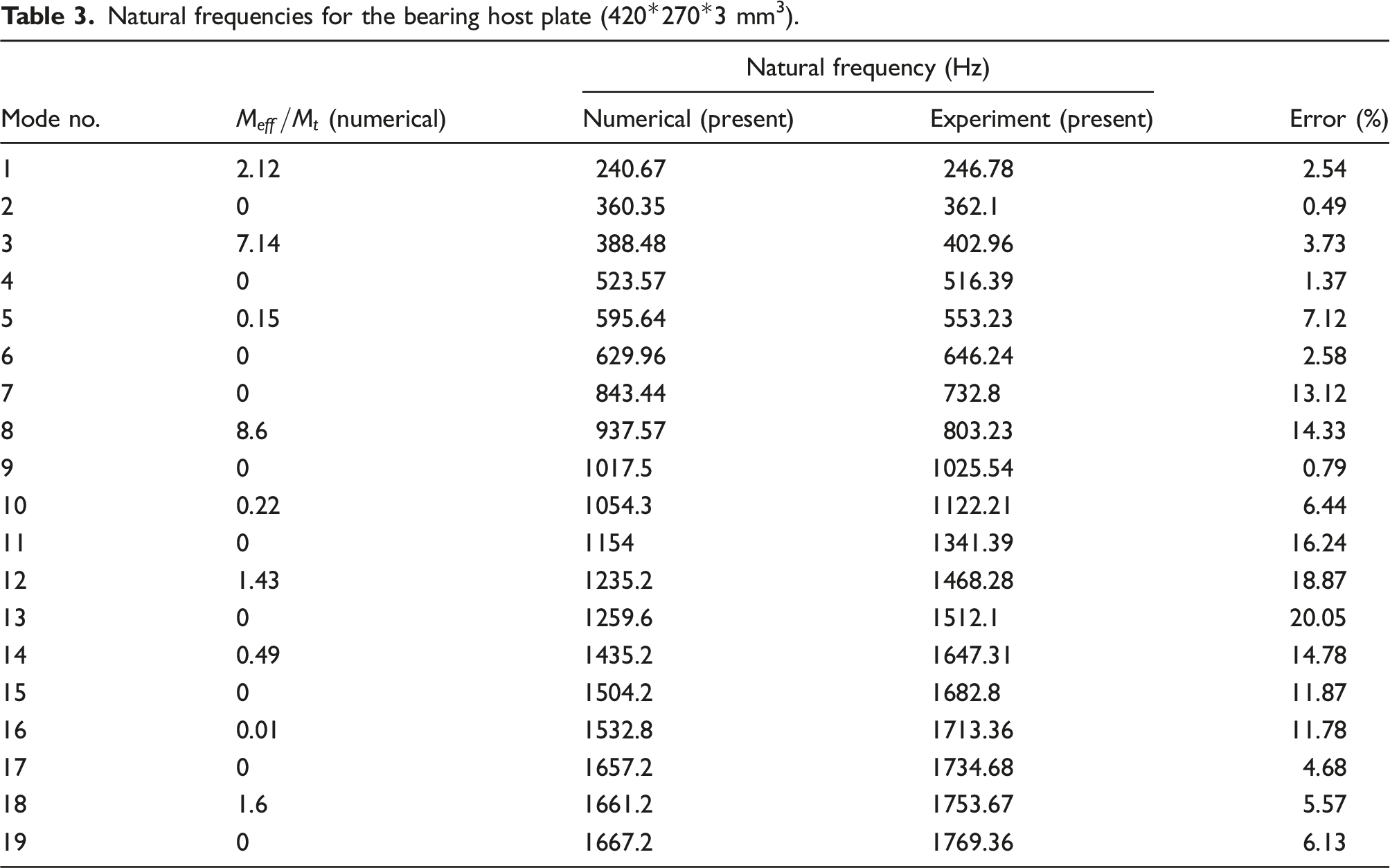
The deformation contour plots for the eigenmodes with the biggest effective mass ratio are shown in Figure 7. It can be observed that primarily the eigenmodes are of out-of-plane type in the studied frequency range. Therefore, the vibration isolator is considered to be normal to the plate plane to provide the greatest isolation effect. Considering the deformation distribution illustrated by Figure 7, the isolator location is denoted by ( Deformation contours of the bearing host plate for the eigenmodes with largest effective mass ratios (The black-colored grid is to help better understand the relative position of points). ) where primarily targets the antinode associated with mode no.8. Additionally, it affects the antinodes corresponding to mode no.1 and, to some degree, mode no.3.
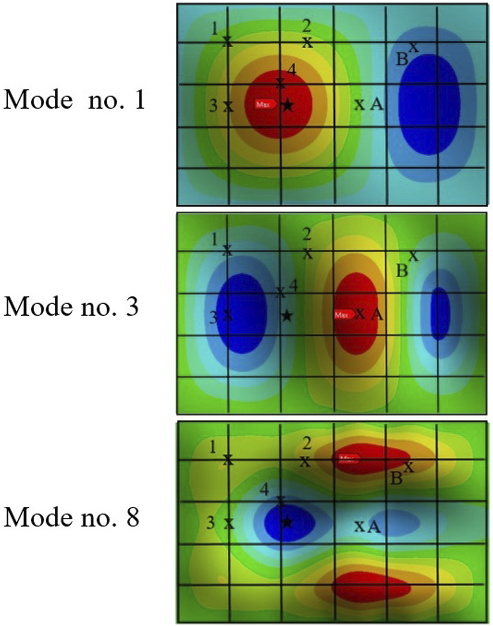
The isolator is located near an antinode corresponding to the first eigenmode and at a distance equal from the shaft and the plate edge. So that the wave transmission mechanism before and after reaching the isolator can be studied. Figure 8 shows the physical setup for the bearing host plate forced vibration test. Points A and B, which lie on symmetric lines with respect to the bearing position, are selected for optimal tuning of the vibration isolator (see Figure 8). The choice of these points is motivated by the aim of minimizing the response at points as close as possible to the excitation source. Positioning the isolator on the bearing host plate, and assigning the optimization and measurement points.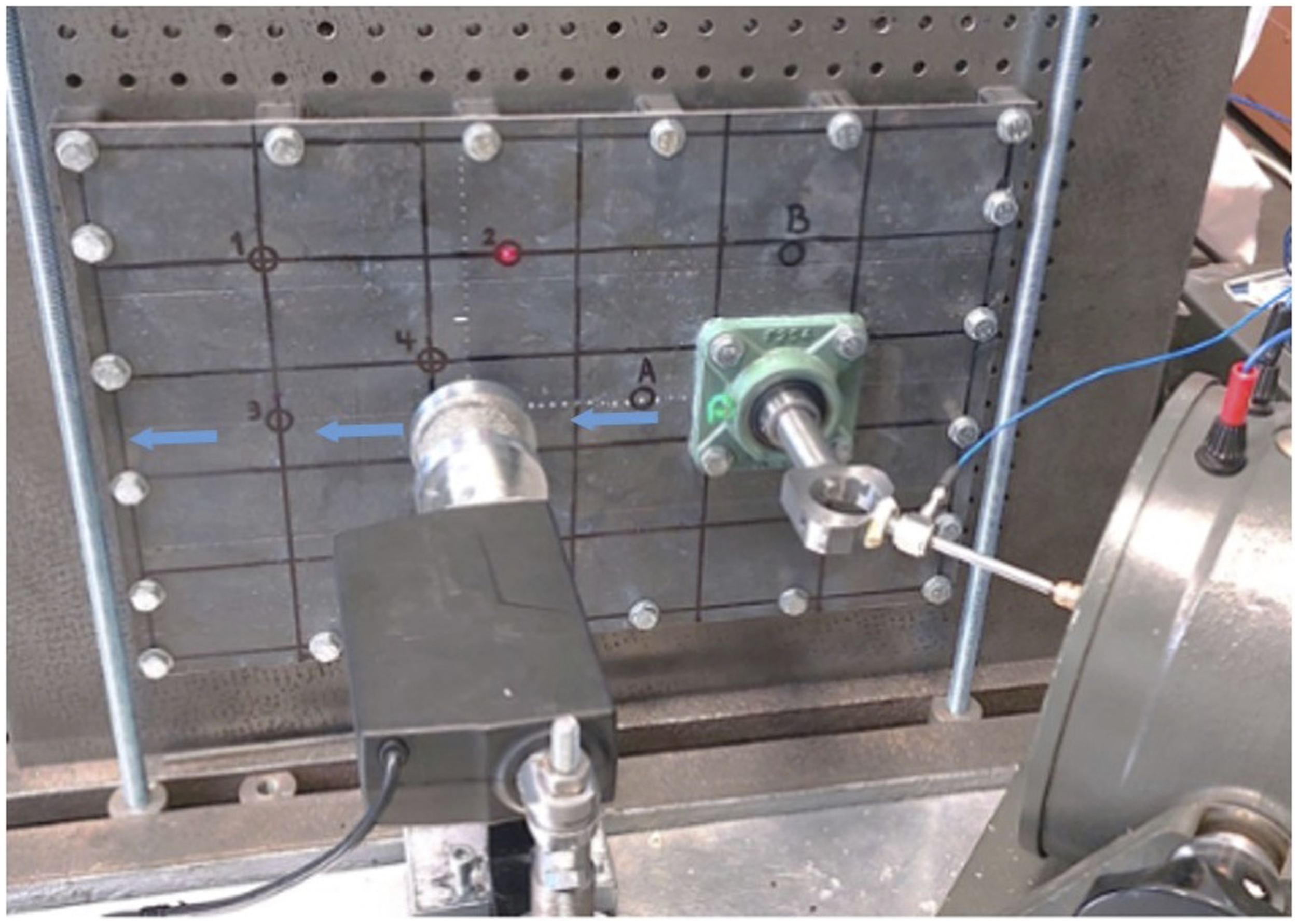
As a result of vibration test under semi-active control, the mobility spectra for points A and B considering a possible range of compression rates are presented in Figures 9(a) and (b), respectively. Frequency response surface for different pre-compression levels associated with the reference response (black line) recorded at points: (a) A and (b) B.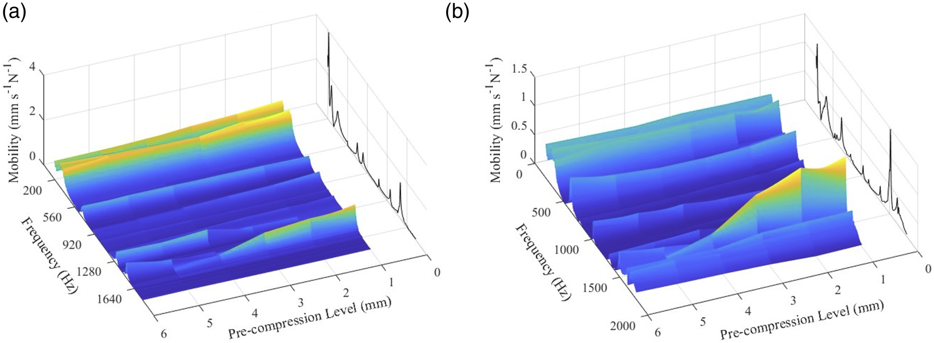
To perform the cumulative optimization, the frequency range is divided into four equal frequency intervals. Each frequency interval is considered for dual objective optimization of pre-compression rate based on minimization of U parameter for points A and B as demonstrated by Figure 10. The cumulative optimization algorithm searches for the minimum value of U common between points A and B. So that it converges after I, II, III, … iterations reaching the optimum value of C for each frequency interval. Convergence of dual objective optimization at different frequency intervals.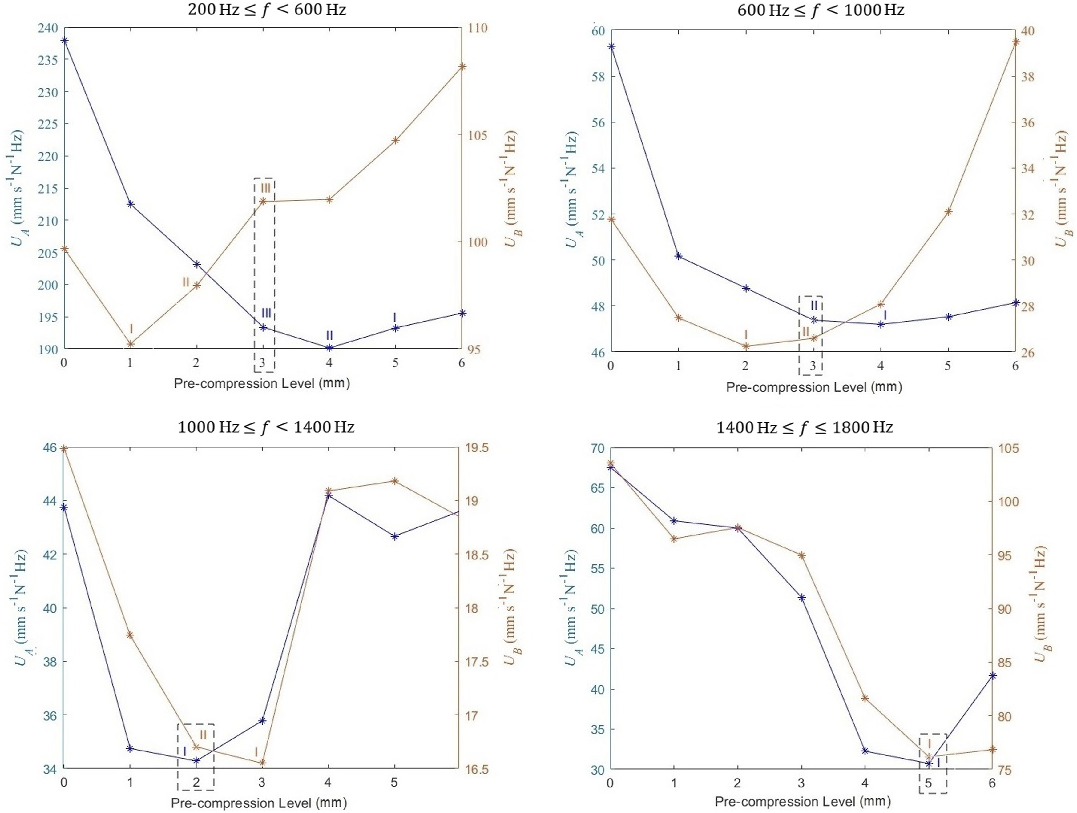
According to the result of optimization, the optimal values of pre-compression for the four chosen frequency ranges are obtained as C
opt1
=3 mm, C
opt2
=3 mm, C
opt1
=2 mm, and C
opt1
=5 mm. So that the optimal control function can be written as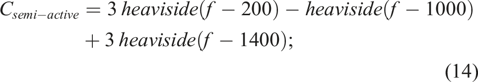
The results of point-by-point and cumulative optimizations at points A and B are illustrated in Figures 11(a) and (b), respectively. It can be determined that when a sine sweep excitation is used, the cumulative optimization is more useful than the point-by-point optimization. The reason is that the cumulative optimization provides a limited number of optimal levels that correlate to specific frequency ranges, whereas point-by-point optimization provides an optimal level for each frequency value. As a result, when cumulative optimization is used, fewer actuator movements are needed, and the transient effect caused by actuation motion is reduced. Result of optimization based on point-by-point (red line), and cumulative (white line) methods associated with the reference response (black line) recorded at points: (a) A and (b) B.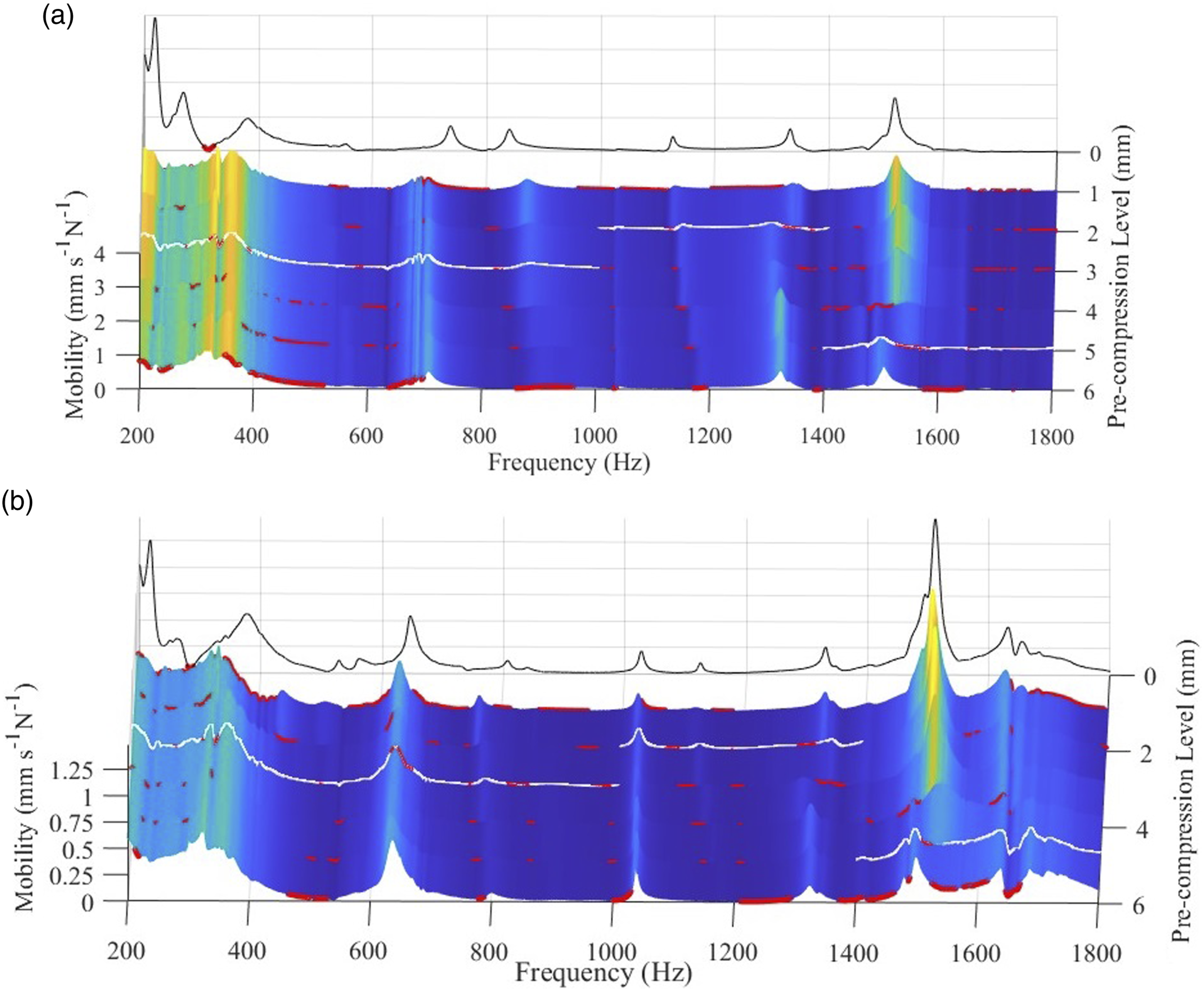
In order to isolate vibrations semi-actively, the control function obtained by cumulative optimization (equation (10)) is used to define the optimal control path for a forced vibration test which takes 200 s indicated by Figure 12. Optimal pre-compression path in frequency and time domains.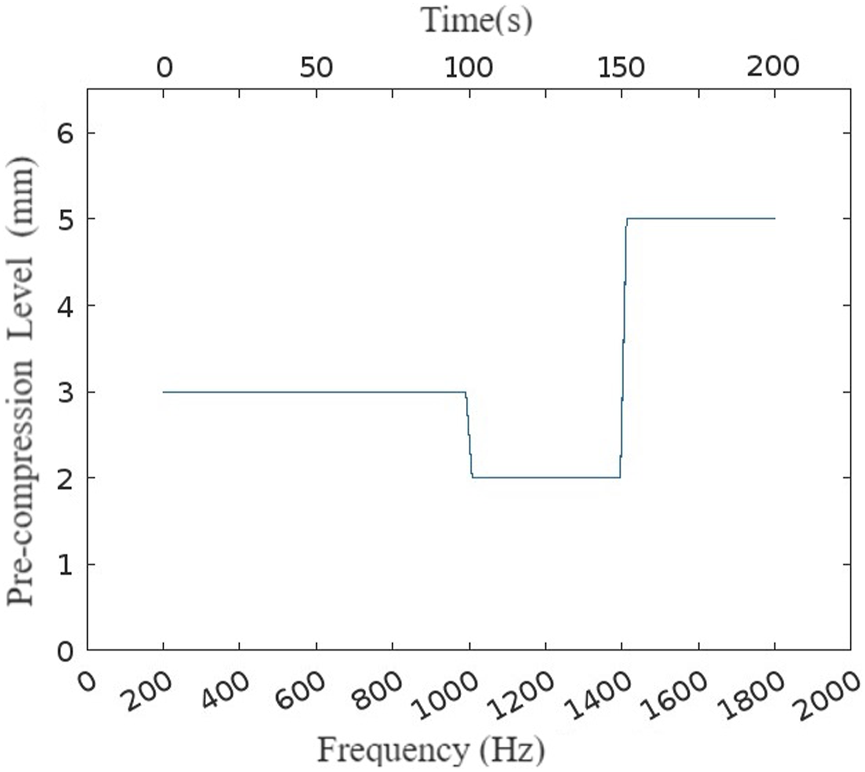
The mobility-frequency response at optimization points with and without (w/o) semi-active control is demonstrated by Figure 13. The isolation rate at points A and B is obtained 13.63% and 5.95%, respectively. Points A and B are important for tuning the optimization; however, the vibration decrease rate at these points is not significant since the optimization points are located far away from the isolator attachment point. Mobility-frequency response w/o semi-active control recorded at points: (a) A and (b) B.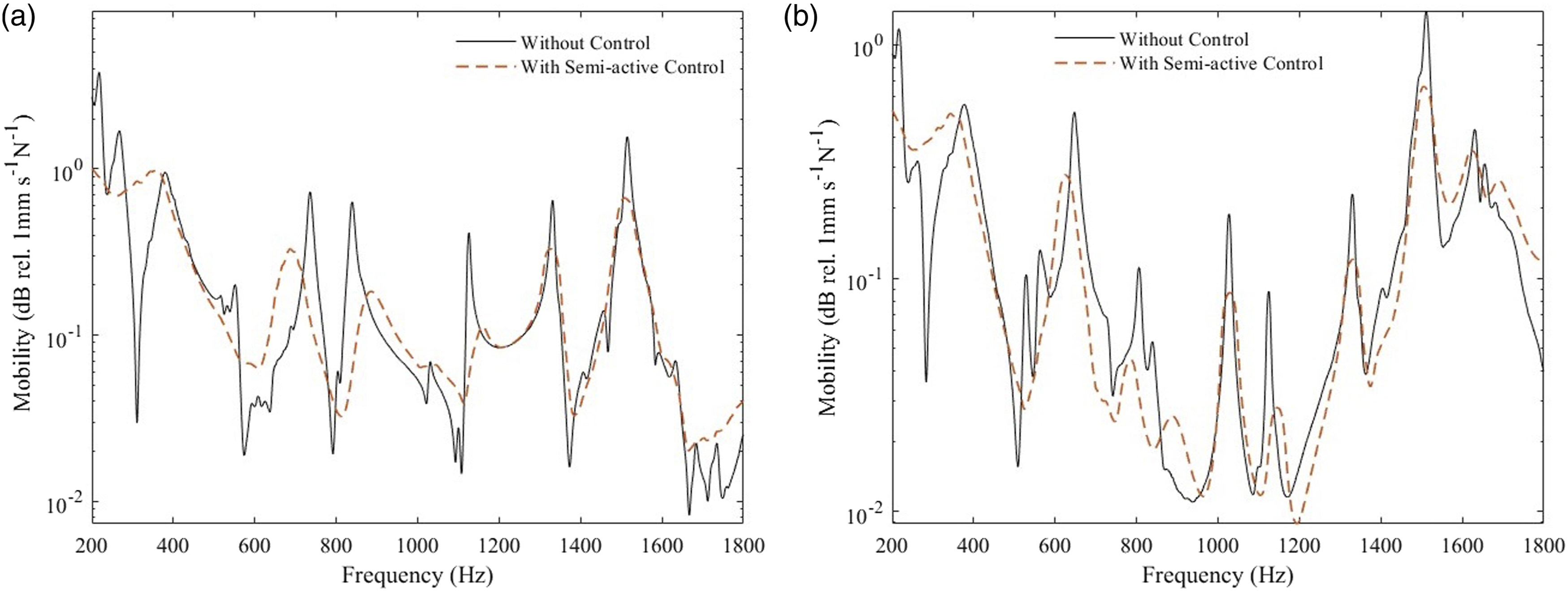
To reach a clear understanding of the structure behavior w/o semi-active control, points 1–4 showed in Figure 8 are considered for measurement. According to Figure 14, the semi-active vibration control led to reduction of vibration by 20.94%, 23.54%, 43.76%, and 55.17%, respectively, for points (1–4). The isolation rate is maximum at point 4 which is the nearest to the isolator attachment position. Considering an elastic wave propagating from the bearing toward point 3, remarked by blue arrows in Figure 8, point A and 3 are located before and after the isolator position, respectively. The isolation rate reported for points A and 3 is 13.63% and 43.76%, respectively. This comparison makes sense since the isolation rate increases when the elastic wave passes the isolator attachment position. A similar justification can be made when points 1 and 2 are compared. Mobility-frequency response w/o semi-active control recorded at points (1–4).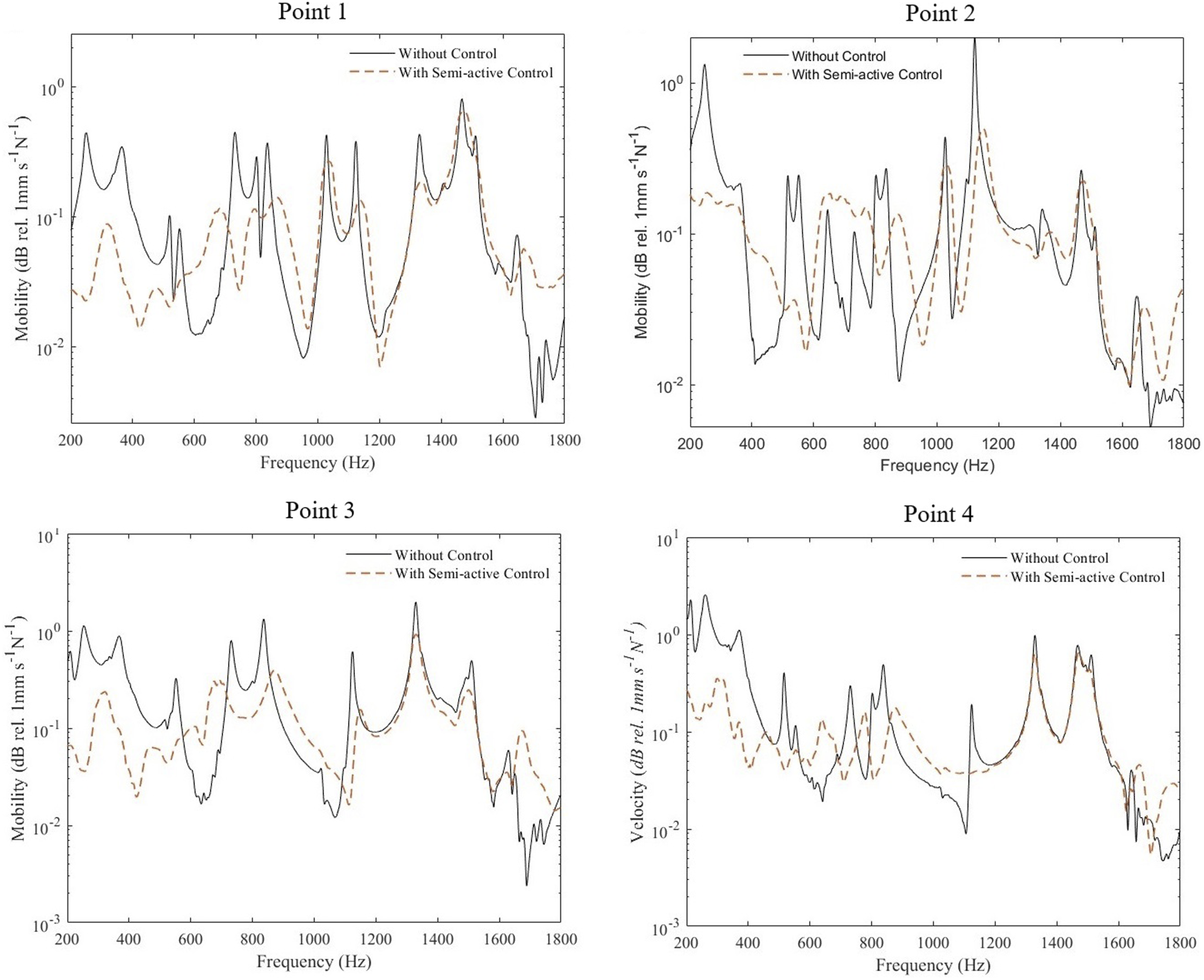
The effectiveness of current semi-active approach for different contributions of excitation load is investigated. For this purpose, harmonic tests for several excitation angles are conducted w/o semi-active control. Figure 15 demonstrates the effect of loading components contribution on the U parameter w/o semi-active control over the whole frequency range recorded at point 4. It can be observed that the semi-active control has led to isolation at all angles; however, the isolation rate is minimum at the angle of 0°. The isolation rate obtained for angles 0, 30, 45, 60, and 90 is 26.76%, 68.86%, 55.17%, 51.75%, and 51.63%, respectively. The isolation rate is minimum for the loading angle of 0° which is expected since the isolator is attached normal to the plate, and loses its efficiency when the normal component of bearing reaction force is much smaller than the lateral one. Effect of loading components contribution on U parameter w/o semi-active control over the whole frequency range (200–1800 Hz).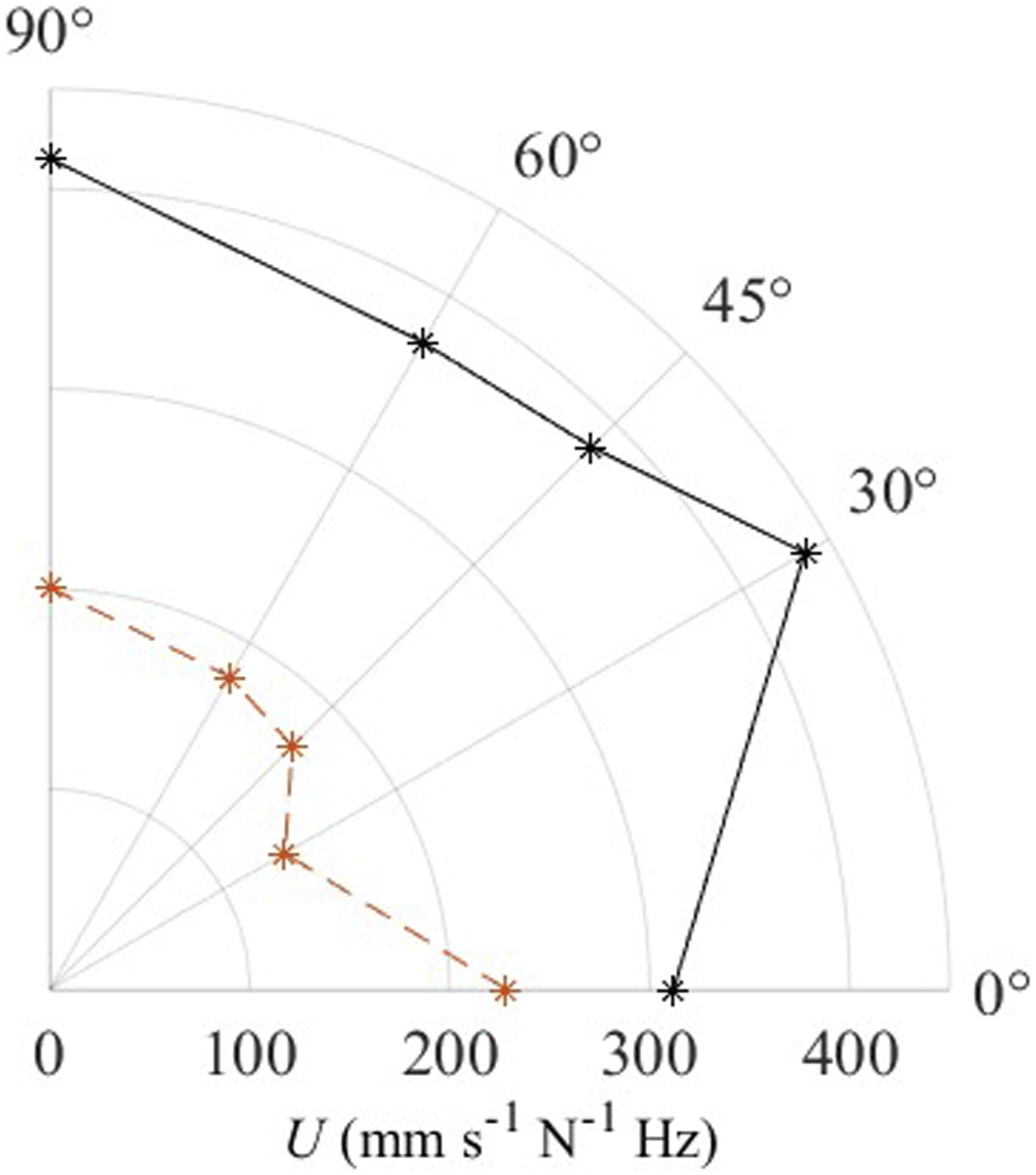
To figure out the influence of loading components contribution on the control approach at resonances, the mobility-frequency response is studied. Although Figure 15 shows that a successful isolation is feasible according to U parameter criteria, the results of mobility amplitude at resonances, reveal favorable and unfavorable effects as reported in Figure 16. It can be observed that a successful isolation of mobility is attained for excitation angles of 30°, 45°, and 60° at resonances 246.78 Hz, 362.1 Hz, 402.96 Hz, 516.39 Hz, 533.23 Hz, 732.8 Hz, 803.23 Hz, and 1122.21 Hz, whereas unfavorable effects attribute to the angles of 0°, 90°, or both of them. Ergo, it can be stated that vibrations can be isolated at the vicinity of isolator attachment point in the frequency range of 246.78–1122.21 Hz for 30°, 45°, and 60° loading angles which offers a wide range of angles for mechanical transmission systems design. Excitation angle of 0° has produced unfavorable impacts in more than 50% of resonances across the entire frequency range. This indicates that the efficacy of isolation decreases when the lateral component of loading is significantly greater than the axial component. Although having unfavorable local effects is inevitable using the semi-active control based on optimal U parameter, they can somewhat be eliminated by reducing the size of frequency interval for optimization of U parameter. It should be also noted that under operational industrial condition, the favorable effects are expected to be higher since the working frequency ranges and excitation angles are determined and limited. Effect of loading components contribution on mobility (mm.s-1N-1) amplitude w/o semi-active control reported at resonances.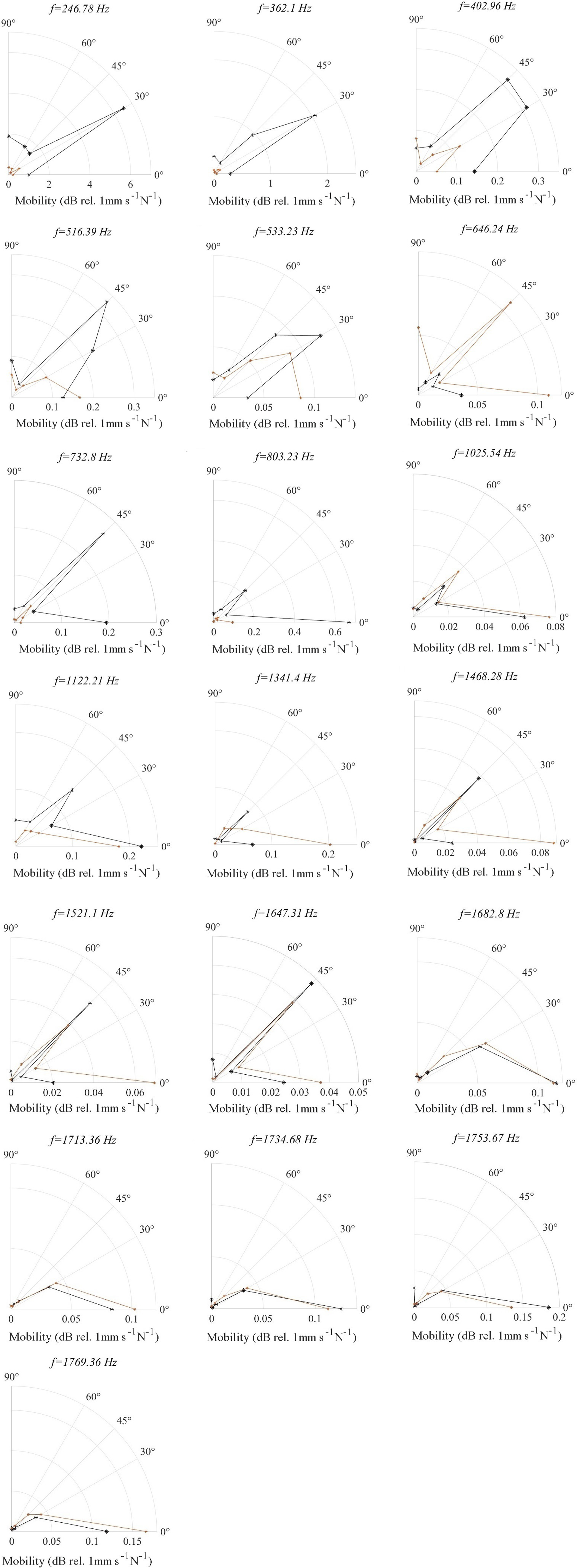
4. Conclusion and summary
This is the first article to present a semi-active vibration control based on MR material, the frequency adaptability of which was previously demonstrated by Rieß and Kaal (2021). The MR potential to isolate vibrations has been first studied using a cantilevered plate whose free vibration behavior is well known. The results revealed 44% reduction of plate free edge mobility amplitude when the MR is compressed only 4%.
The result obtained for vibration isolation of the cantilevered plate provided the confidence to employ the MR-based isolator for a bearing host plate, as a practical example. In this regard, the isolator has been positioned according to the analysis of eigenmode shapes obtained by numerical simulation. The excitation has been applied with an angle of 45° to impose comprehensive reaction forces. A point-by-point numerical optimization led to a heavily variable control path which implementation is not feasible for a sine sweep excitation since the control state should be changed repeatedly, inducing many transient effects. For this reason, the results have been optimized through a cumulative method which minimizes the U parameter in frequency ranges, and proposes a control function based on Heaviside functions. With the help of Heaviside functions, optimal values of control variable, C, have been introduced not for each frequency value but for four frequency ranges of the same size. Hence, the actuator required to move for fewer times. So that an open-loop semi-active control strategy has been developed for a given frequency range based on the cumulative optimization results to isolate the vibrations.
Studying U parameter values at a point near the actuator attachment position, isolation rates of 26.76%, 68.86%, 55.17%, 51.75%, and 51.63% have been recorded for the excitation angles of 0°, 30°, 45°, 60°, and 90°, respectively, using the current semi-active control. The parametric study on the angle of excitation revealed that the semi-active control efficiency reduces when the lateral component of excitation force is much bigger than the axial one.
Finally, the MR-based semi-active vibration control has been shown to be powerful, and efficient for vibration isolation due to the high adaptability of MR stiffness and damping which provides the possibility for wide-band tuning. In further research, it would be possible to consider the potential of the proposed method in noise and vibration control of commercial mechanical transmission systems.
Footnotes
Acknowledgments
The author would like to thank Dr Arkadiusz Mróz, Dr Marek Kokot, Mr Damian Sala, Mr Janek Biczyk, and Dr Krzysztof Sekuła employed by Adaptronica sp. z o. o. R&D company for their valuable insights and support during this research. In addition, the author wishes to thank Timotion company for offering TA29 linear actuator and providing technical advice.
Declaration of Conflicting Interests
The author(s) declared no potential conflicts of interest with respect to the research, authorship, and/or publication of this article.
Funding
The author(s) disclosed receipt of the following financial support for the research, authorship, and/or publication of this article: This project has received funding from the European Union’s Horizon 2020 research and innovation program under the Marie Skłodowska-Curie grant agreement No. 860243. The author would like to acknowledge all the Institutions and Partners involved within the LIVE-I project.