
Abstract
Increasing the service-life of engineering structures such as aeroplanes is a major issue in order to enhance their cost-effectiveness and to reduce the carbon footprint. One possibility to achieve this goal is to determine the current structural health state and to derive respective measures in order to increase the structure’s technical reliability. For doing so, a structural health monitoring system consisting of both an actuator and a sensor network may be applied. Whereas the actuator induces a wave field of guided ultrasonic waves, the measuring data of the sensors allows to determine the health state of the respective structure. However, both actuators and sensors in most cases distort these wave fields. This distortion may lead to false-detection of damage: both the number and severity of damage may be over- or underestimated. The former leads to an unnecessary high effort for retrofitting the structure, whereas the latter reduces the structure’s technical reliability. Several measures exist in order to avoid such false-detections. In the present contribution, focus is set on reducing the distortion of the wave field which is caused by an embedded sensor. The reduced distortion of the wave field is achieved by an acoustic impedance matching with a functionally graded material which is based on a mechanical model. The approach additionally results in amplified measuring signals of the sensor. The applicability of the proposed approach is shown by means of a numerical study.
Keywords
1. Introduction
Structural health monitoring (SHM) of thin-walled, large-scale structures made of fibre-reinforced polymer (FRP) or fibre metal laminates (FMLs) is subject to current research (Balageas et al., 2006; Giurgiutiu, 2008; Lammering et al., 2018; Su and Ye, 2009). Most of these SHM approaches use guided ultrasonic waves (GUWs), in this case referred to as
There are numerous parameters which influence the distortion of a wave propagating through a structure. Major parameters are related to (i) the geometry of the obstacle and (ii) the material configuration. The latter is mostly determined by the acoustic impedance, as abrupt changes in the acoustic impedance lead to reflections (Rose, 2014).
Studies regarding the distortion of wave fields by means of a single obstacle (i.e. a sensor) were performed for 3D-printable piezoelectric composite sensors with acoustically adapted material properties (Roloff et al., 2022) and sensors with different shapes. Exemplary shapes of current practical relevance are circular, elliptical, rectangular or lozenge shapes, respectively (see Figure 1). For analytical and numerical investigations exemplary reference is made to Achenbach (1993); Pao and Mow (1971). In addition, the propagation of flexural waves in a plate where scattering was caused by circular holes that extend through the entire thickness of the plate was investigated in, for example, Norris and Vemula (1995). Sketch of the problem: (a) structural health monitoring in composites of GLARE-type and (b) possible design of the sensor housing, taken from Haus et al. (2021).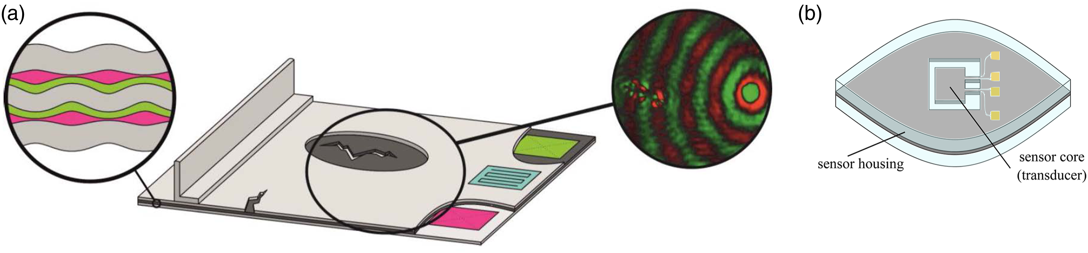
However, previous experimental and numerical investigations showed that the interphase region between obstacle and embedding host plays a tremendous role for the wave propagation. Herein, the interphase is caused by curing processes as they occur in FML, carbon fibre–reinforced plastics or reinforced steel (Matonis, 1969; Zhao et al., 2021).
With respect to the wave propagation, the underlying effect of changing impedance can be induced artificially by encasing the obstacle (Cai, 2004; Mal and Yang, 1993) or by surrounding it with one or more layers of other materials (Weber and Mechtcherine, 2017).
Novel MEMS vibrometer sensors to detect GUW are developed by the research unit the authors participate in (Haus et al., 2022). These sensors are made out of silicon and borosilicate glass and have a square footprint of 2 mm2 and a height of less than 500 μm, which is why they are predestined to be integrated into a laminated FRP or FML structure. In future work, the sensor housing’s geometry could be adapted for specific purposes. A possible sensor housing design is presented in Figure 1(b). This enables embedded SHM systems using GUW in FML, a subject mainly inspired by aircraft inspection engineering. However, a sensor which is positioned inside the structure to be investigated is an obstacle itself influencing the wave propagation. This results in reflections that interfere with waves reflected from, for example, damage, and thus, a false-detection of damage may occur. In addition, reflected wave energy at the interface between structure and sensor does not enter the sensor and decreases the signal amplitude. Furthermore, SHM systems mostly work with actuator–sensor networks. In such a configuration, numerous actuator–sensor paths exist which result in waves approaching the sensors from different directions. The challenge is to integrate a sensor in such a way that reflections of GUW from all directions are minimised and transmission into the sensor is maximised. This would lead to SHM systems with increased performance.
The huge influence of impedance jumps at interfaces as well as the influence of varying material properties in transition zones on the wave propagation behaviour in both isotropic materials and laminates has been shown analytically and numerically see, e.g. Matonis (1969); Pao and Mow (1971); Rittmeier et al. (2018); Weber and Mechtcherine (2017); Zhao et al. (2021). In an inverse procedure, the underlying mechanical phenomena allow the design of interphases in order to achieve a SHM specific goal. One goal is to reduce the scattering of GUW due to integrated sensors. Embedding sensors in a metamaterial leads to acoustic cloaking, that is, an incoming wave is bypassed around the sensor, and consequently, the wave field is hardly influenced by the sensor. For the design of respective materials, refer, for example, Futhazar et al. (2015). However, if the sensors are invisible to an incoming wave, they cannot measure physical quantities related to wave propagation, and thus, a SHM would be impossible. Thus, the aim of designing an artificial interphase between a sensor and the embedding host should be to (i) reduce the GUW distortion caused by the sensor and (ii) amplify the GUW signal to be measured by that sensor. The present contribution intends to provide a numerical feasibility study on a planar functionally graded material (FGM) using a step-wise acoustic impedance matching in concentric rings around a circularly shaped sensor. The material of the structure is assumed to be epoxy resin, and the material of the sensor housing is given in Haus et al. (2022). The focus is set on homogeneous, linear elastic, and isotropic materials for both the host medium and the sensor housing.
With regard to matching the acoustic impedance in epoxy resin structures, the introduction of particles into the matrix is state of current research, especially for piezoelectric ultrasound transducers. Here, a backing layer is introduced that is matched in acoustic impedance to minimise the wave distortion of the sensor while amplifying the wave signal at the sensor location. A typical kind of particles used are tungsten particles (Duranteau et al., 2016; Webster, 2009; Zhang et al., 2019). Another option is a graded acoustic impedance in FGM, where the material properties of the two media are connected via a transition zone to replace the impedance jump by a smooth gradient (Im and Park, 2022; Reddy, 2000). However, in most cases, the impedance matching takes place in the thickness direction of a structure or within a connecting layer. When considering obstacles influencing GUW in thin-walled structures, the gradient has to be smoothed in-plane in a planar configuration which is more challenging during fabrication.
From the literature review, the following research questions emerge to be addressed in this publication: Can a planar, spatially limited material modification efficiently reduce reflections and increase the transmission of GUW into a sensor embedded in a FRP or FML and how should the material properties be designed to achieve the best performance?
To answer these questions, the present contribution is outlined as follows: Fundamental aspects of wave propagation and the theory of acoustic impedance are presented in Section 2. The application approach to realise a FGM in the context of this contribution is introduced in Section 3. The numerical model for the feasibility study is presented in Section 4 and the obtained results are discussed in Section 5. A summary and an outlook are provided in Section 6.
2. Theory on acoustic impedance matching
Most of the GUW interactions with obstacles stated in Section 1 appear due to asymmetric variations in thickness or changes in material properties (acoustic impedance). In the far field of an acoustic source in a solid, the acoustic impedance Z is defined as the product of the density ρ and the phase velocity cp

The far field assumption is valid if the distance to the acoustic source is larger than 1.5 times the wavelength λ (Sinapius, 2018).
The acoustic impedance plays a key role for the occurrence of reflections at the interface between two media. For the following remarks, it is assumed that the wave propagation direction is perpendicular to the interface. In this case, the reflection coefficient R and the transmission coefficient T can be expressed in terms of acoustic impedances for a wave travelling from medium Z
i
into the adjacent medium Zi+1, respectively (Bergman, 2018; Kaltenbacher, 2018; Rose, 2014)
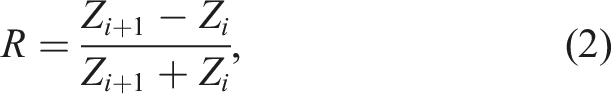
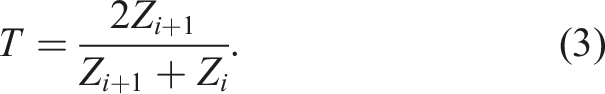
Equations (2) and (3) show that reflections are minimised and transmission is maximised if the acoustic impedances of the two media are equal.
The influence of the phase velocity of a material needs further investigation as it strongly depends on the propagating wave form. In the SHM applications under investigation,
For the simple case of an isotropic, homogeneous material like pure epoxy resin, an analytical description to determine the phase velocity of
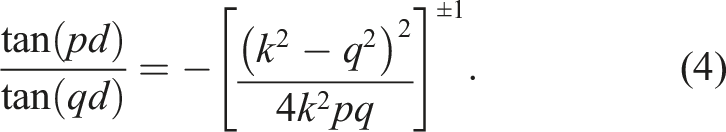
The exponents of +1 and −1 describe the formulations for symmetric and asymmetric modes, respectively. k denotes the wave-number and d the half thickness of the structure. The parameters p and q depend on the natural angular frequency ω = 2πf with frequency f and are defined as
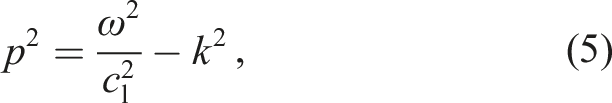
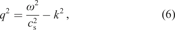
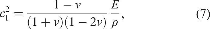
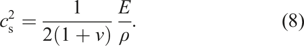
Herein, E describes the
The group velocity cg corresponds to the propagation of a wave package and can be expressed as
Equations (4)–(10) show that the phase and group velocities of
These properties need to be modified to match the acoustic impedance of two media in order to reduce reflections and increase the transmission.
3. Application approach for a planar FGM
Material properties, taken from Lange+Ritter (2021); METALCOR (2021); Schott (2021).
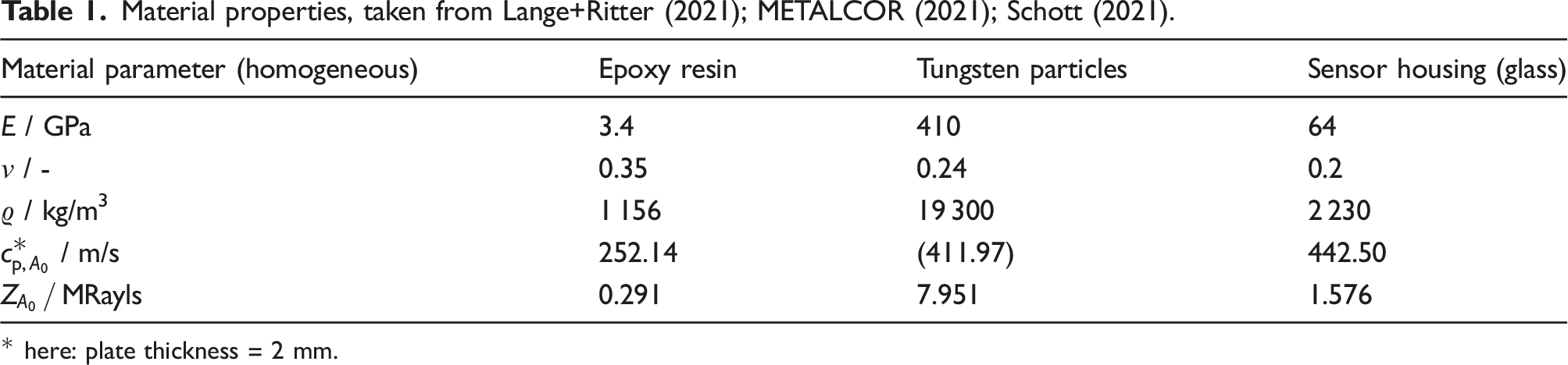
* here: plate thickness = 2 mm.
The approach is to use a planar FGM with adapted material properties of the epoxy matrix in the vicinity of the sensor. A circular, concentric arrangement is chosen to be direction independent. In an ideal case, a continuous pattern would lead to the best results. In this numerical feasibility study, the impedance matching will take place in a step-wise manner for numerical and experimental simplicity. The general idea is depicted in Figure 2. Sketch of the numerical model with integrated sensor and 5-step interphase.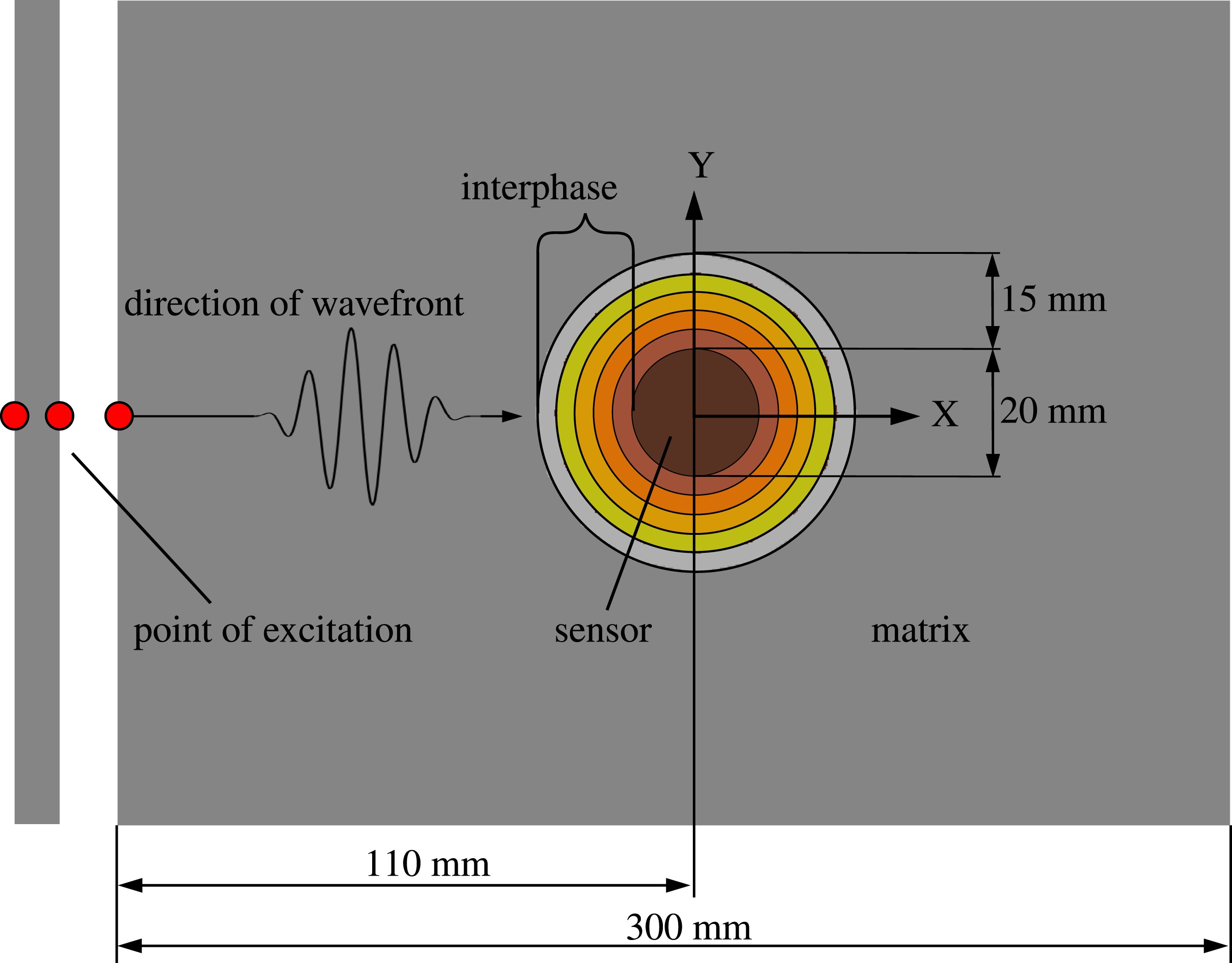
The schematic representation (Figure 2) in combination with the material properties in Table 1 reveals that a particle distribution with a high particle content in the adjacent region of the sensor to match the acoustic impedance of the sensor and a particle content of zero on the outside of the interphase to match the one of the surrounding epoxy resins is needed.
Experimental implementation encounters some challenges such as sedimentation and agglomeration of the particles. While gradients along the thickness direction are state of the art, the requirement of an in-plane gradient as well as the need for higher particle contents in the middle increases the complexity of manufacturing as methods such as centrifugal processes are difficult to apply. All these challenges will be addressed in a future experimental work and are thus neglected within the present work.
4. Numerical model
4.1. General remarks
In this numerical study, the authors restrict themselves to a circular shape of the glass housing for the sensor for simplicity. As described in Section 2, it is necessary for the numerical model to allow for a gradient in the material properties with the gradient directed in the radial direction of the (circular) sensor housing. The acoustic impedance matching will be performed experimentally by adding tungsten particles, that are assumed to be spherical in this contribution, into the yet uncured matrix. Evaluating wave propagation through an irregular arrangement of spherical inclusions is computationally expensive see, e.g. Boyev and Sumbatyan (2017); Egel et al. (2017); Ma et al. (2017). This numerical effort is further increased if local curing effects in the vicinity of each tungsten particle are also taken into consideration. For an analytical approach dealing with related issues, refer, for example, Matonis (1969); Weber et al. (2013).
For the present numerical feasibility study, the interphase region between the sensor glass housing and the pure matrix is modelled as a homogeneous material with material properties varying step-wise in the radial direction (see Figure 2). For doing so, a discretisation by means of concentric rings of homogenised material is performed. A similar approach has been chosen in Weber and Mechtcherine (2017). Perfect bonding at all interfaces is assumed. For an approach that allows modelling damage in the circumferential direction, see, for example, Weber and Manolis (2017). The more concentric rings are used, the better the approximation to an optimal continuous gradient of the material parameters.
4.2. Model development
In this study, the circular interphase around the embedded sensor is assumed to have a radius that is 15 mm larger than the radius of the sensor (see Figure 2). The size of the interphase is restricted by the production process used in a future work for experimental validation of this numerical feasibility study.
Each concentric ring (step) of the interphase has a radial thickness of 3 mm, resulting in a 5-step interphase. The change in material properties within the interphase steps results from an increase in tungsten content in the epoxy matrix towards the sensor. Using a homogenisation approach according to Chamis (1984); Lammering et al. (2018); Schürmann (2007), the mechanical parameters of both the tungsten particles and the epoxy matrix are smeared, resulting in a homogeneous material with isotropic and linear elastic properties.
As can be seen from equation (2), the change in impedance must be as small as possible to reduce the reflection coefficient. For this reason the impedance was chosen as the guiding parameter for the change of the material parameters within the interphase. With the chosen approach, the maximum mass content ϕ{W,max} = 0.0813 of the tungsten (W) particles inside the epoxy resin (EP) could be determined, and the material parameters 


The resulting values for the given parameters and the acoustic impedance of the interphase matrix–glass housing of the sensor are given in Figure 3. Material properties of the interphase for increasing tungsten content (linear, quadratic, cubic, and square root function): (a) tungsten content, (b) density, (c) 
It should be noted that the mixing rule of CHAMIS (1984) used here to homogenise the material parameters has been developed and verified for the calculation of unidirectional, fibre-reinforced laminate layers (UD laminate). The aim of this work is to prove the concept of a planar FGM without determining exact volume fractions of particles needed in an experimental validation. In this case, more complex models are needed to determine the relation between particle volume fraction and the corresponding material parameters (Webster, 2009). However, the simplified assumption used to determine the material parameters of the interphase is sufficient within the scope of this contribution. In order to adjust the material properties of the interphase so that the change in acoustic impedance is as small as possible, as required in equation (2), the governing material properties density and phase velocity have to be fitted according to equation (1). The density can be calculated analytically using equation (13). But the phase velocity as given in equation (9) or, more precisely, the wave-number can only be determined numerically. For plates with a small thickness h (in our case 2 mm), the numerical calculation can be circumvented if the phase velocity is approximated according to Möser and Kropp (2010).
The approximation using equation (14), under compliance with the required boundary condition and the used frequency, leads to tolerable deviations of 
A 5-cycle, 
This scaled and time-dependent force amplitude F(t) is applied as a point load at the edge of the plate on the top and bottom as depicted in Figure 2. At both positions, the force vector is applied in the same direction to uniquely excite the asymmetric A0-mode.
Similar to other authors who have investigated comparable wave propagation phenomena (Bellam Muralidhar et al., 2021), an excitation force of Dispersion diagram of the A0-mode for a 2 mm plate out of epoxy, calculated using the Dispersion Calculator (Huber, 2018).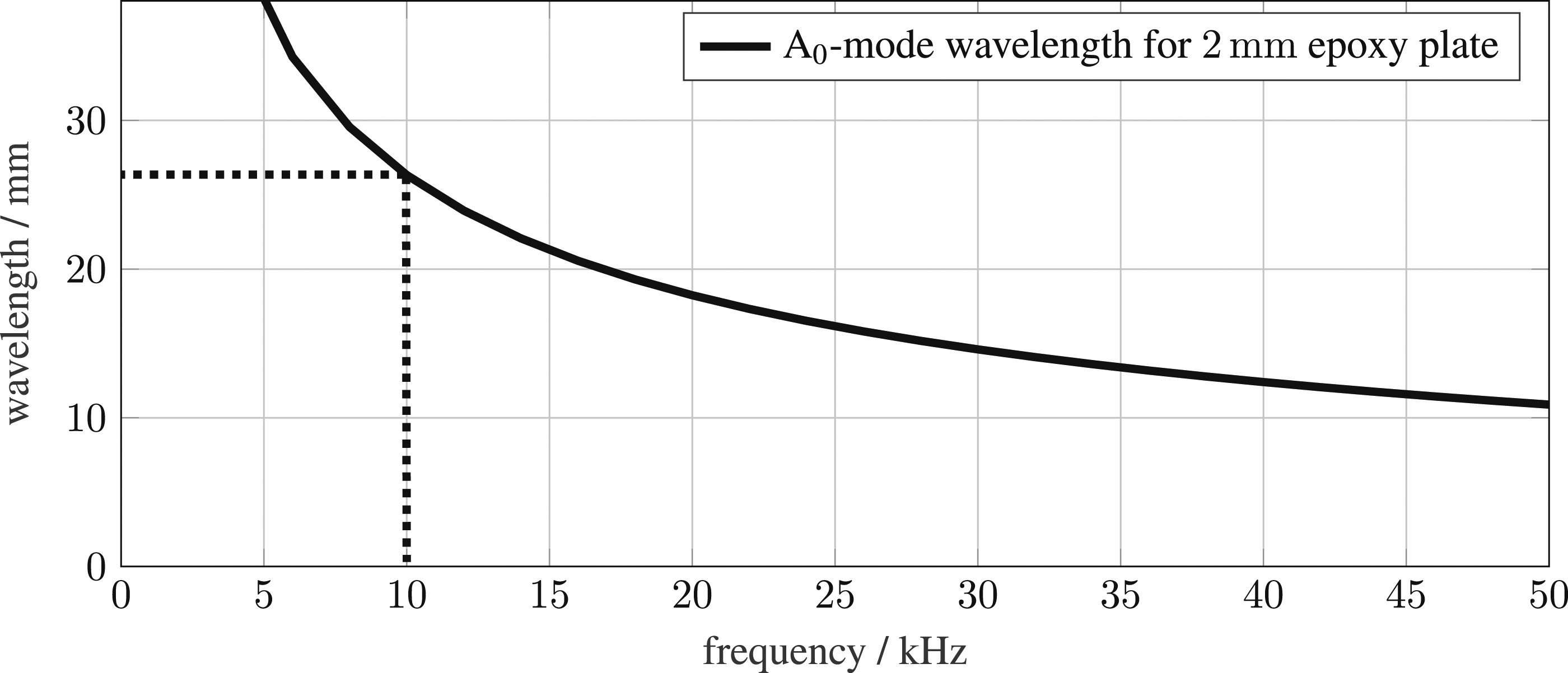
5. Numerical results
For the numerical model developed in Section 4, numerical results are presented and discussed in the following.
The evaluation of the simulations is based on the normalised out-of-plane displacement u(t) of the vibrating structure. The evaluation positions should fulfil the requirement that the signal to be evaluated is represented free of reflections from the model boundaries to ensure that only wave components resulting from the interaction between matrix–interphase and interphase–sensor are used.
Two positions are chosen for the evaluation of the wave field: (i) the top excitation point as marked in red in Figure 2 and (ii) the centre of the sensor at its top surface. In addition to these local perspectives, the wave signal is evaluated at several points on the top surface, which are located on a straight line between the excitation point and the centre of the sensor and extend along the entire width of the plate. These individual points to be evaluated have a distance of 1.3 mm which corresponds to the mesh element size. The resulting B-Scan provides information about the global behaviour of the wave field.
In Figure 5, the B-Scans for the different interphase functions are shown with an adjusted scale so that the amplitudes are visible in all ranges. The qualitative course of the representation does not change as a result of the scale adjustment. The white area represents the sensor, whereas the black line represents the beginning and end of the interphase. In the following sections, the wave propagation phenomena are investigated from both the local and the global perspectives. Normalised and scaled B-Scan of the A0-mode for different interphases: (a) no interphase, (b) linear interphase, (c) square root interphase, (d) quadratic interphase, and (e) cubic interphase.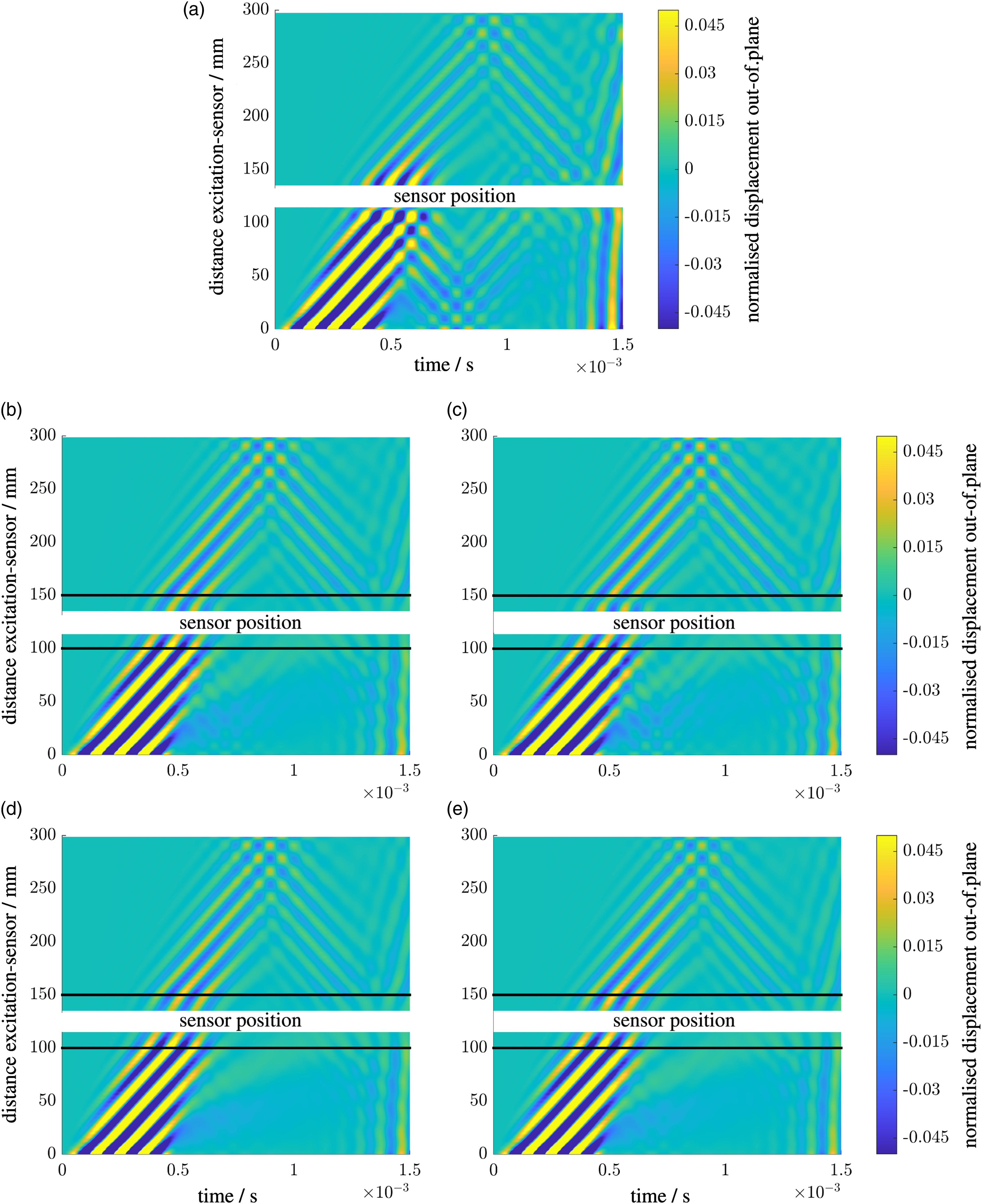
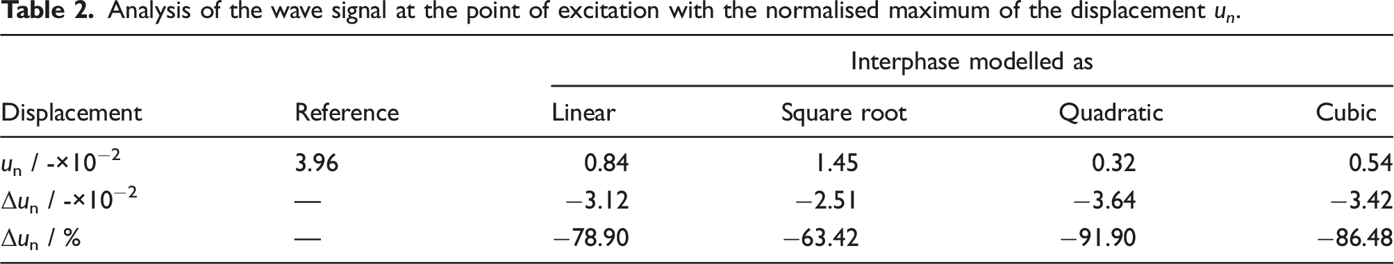
As given in Section 1, the present work aims at designing the interphase between matrix and sensor such that (i) the reflections caused by a sensor are reduced and (ii) the signal measured by a sensor is amplified. To quantify the influence of the interphase, the maximum amplitudes obtained for individual models of the interphase are evaluated at the excitation point and the centre of the sensor and compared to the reference case, that is, no interphase (hard impedance jump). Here, the maximum of the wave signal was calculated from the absolute maximum of the upper and lower envelopes. Under trivial circumstances, such as single impedance jump, it would make sense to use the change in the reflection and transmission coefficient for evaluation. However, multiple impedance jumps lead to strongly interfering signals and would conflict with the required criteria at the evaluation points. The evaluation used here shows analogously how the interphase influences the wave propagation behaviour.
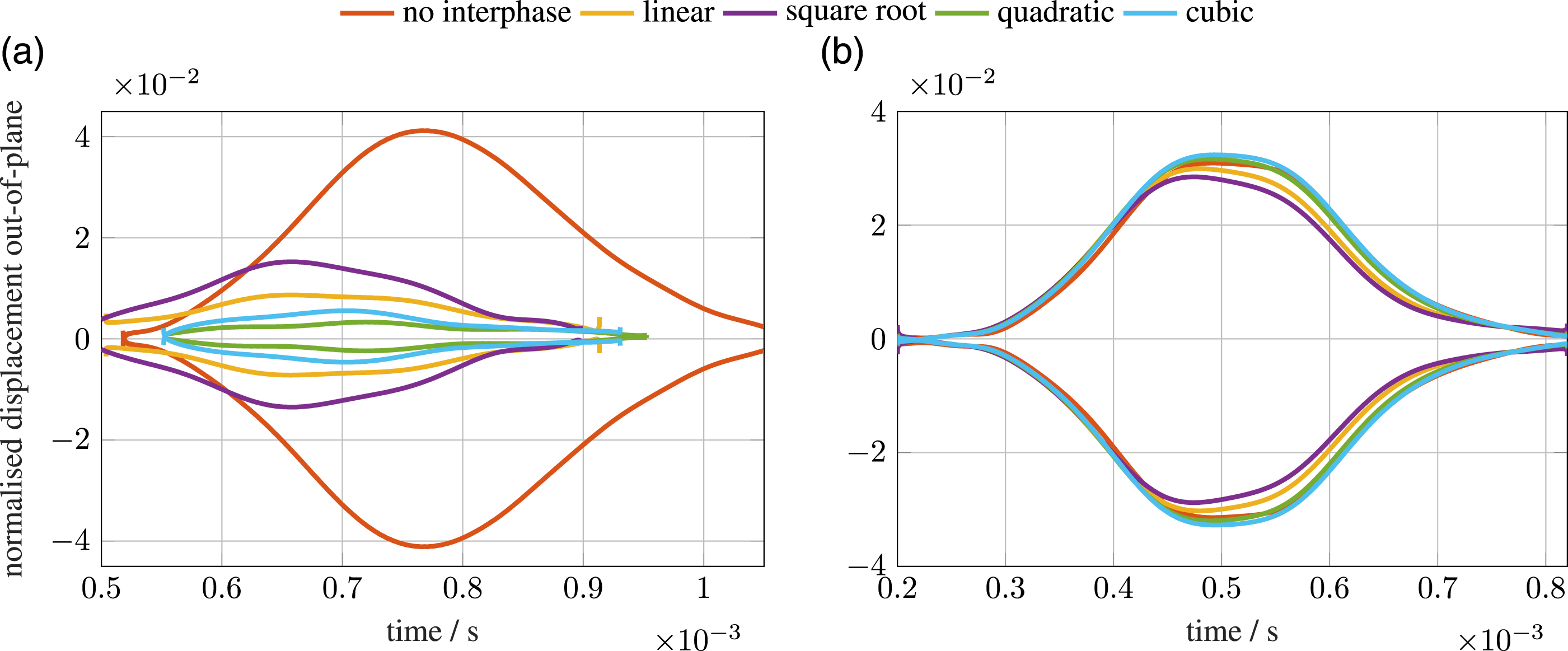
The results of the reflected wave components at the excitation point are shown in Figure 6 and in Table 2. It can be seen in Figures 6(b) and 7(a) that the wave components reflected from the interphases show a reduced maximum in amplitude compared to the variant without interphase. Normalised displacement u of the structure at the point of excitation in the time domain at 10 kHz: (a) structural response at the excitation point and (b) amplification of the reflected wave package (area marked red). Analysis of the wave signal at the point of excitation with the normalised maximum of the displacement u
n
. Envelope curve of the excitation point (a) and centre of the sensor (b) for different interphase functions, cropped in the relevant range.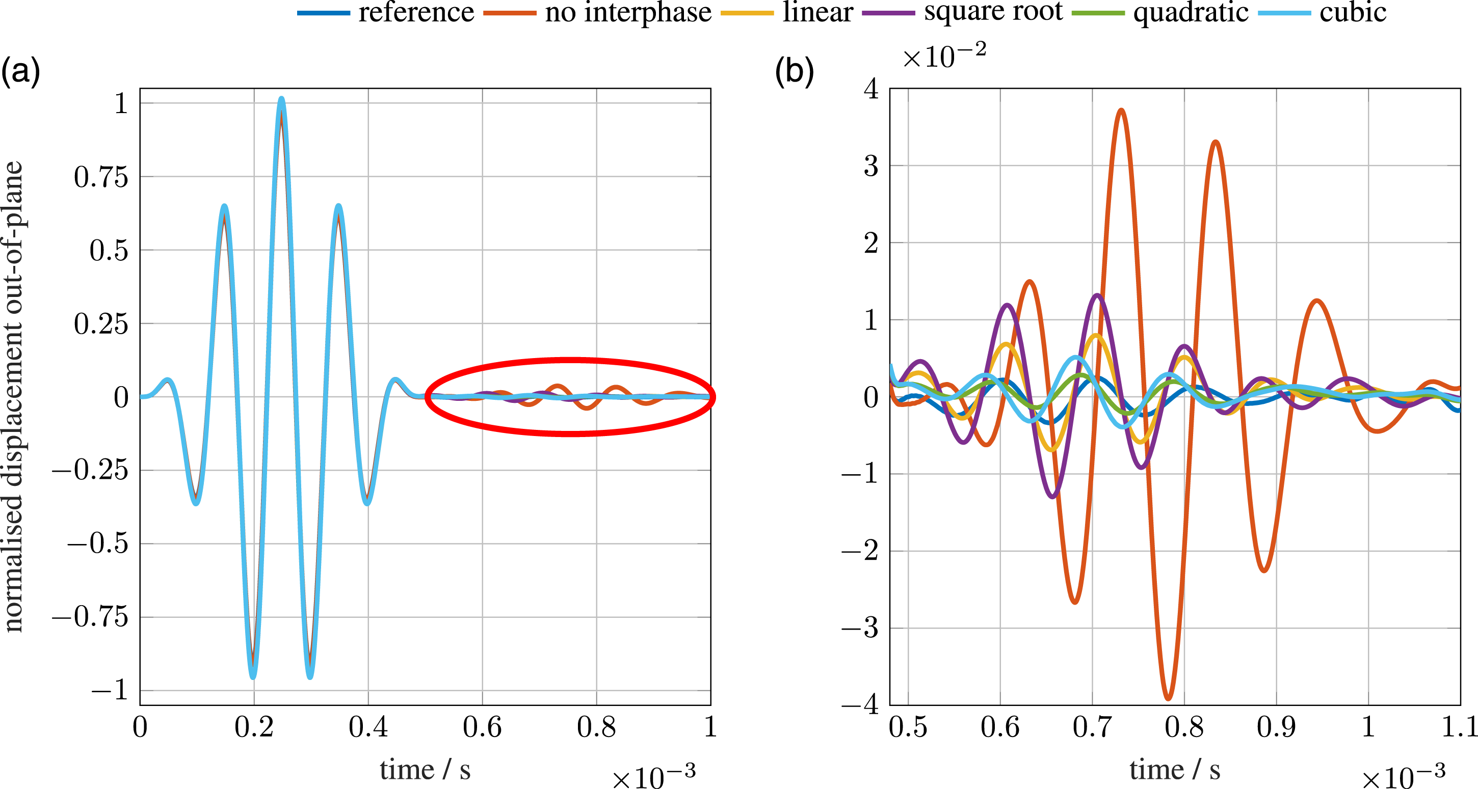
Average and total values of the reflection coefficient for different interphase functions in comparison to the variant without interphase.
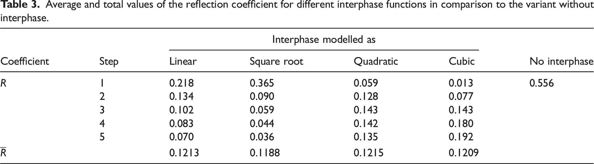
If it is assumed that the interphase with the lowest mean reflection coefficient has the greatest advantage, it would be reasonable if there is just one material jump. This shows that the reflection of the wave package also depends on the configuration and especially on the initial impedance jump at step 1, that is, matrix–interphase boundary, the step the wave package hits first. Here, the quadratic and cubic interphases show a great advantage, since they have particularly low impedance jumps in the first two steps. The reflection coefficient also shows that these interphases have better values in the first steps. However, the configurations with the quadratic and cubic interphases show a significant increase in material jump in the later interphase steps. This can also be seen in Figure 8 as the quadratic and cubic interphases start quite optimally and then deteriorate. The situation is different with the linear and square root interphases, which get closer to the optimal value as the number of interphase steps increases. Nevertheless, the large jumps at the beginning of the interphase lead to strong reflections that cannot be compensated for in the course of the interphase. Reflection coefficient for different interphase functions in comparison to the variant without interphase.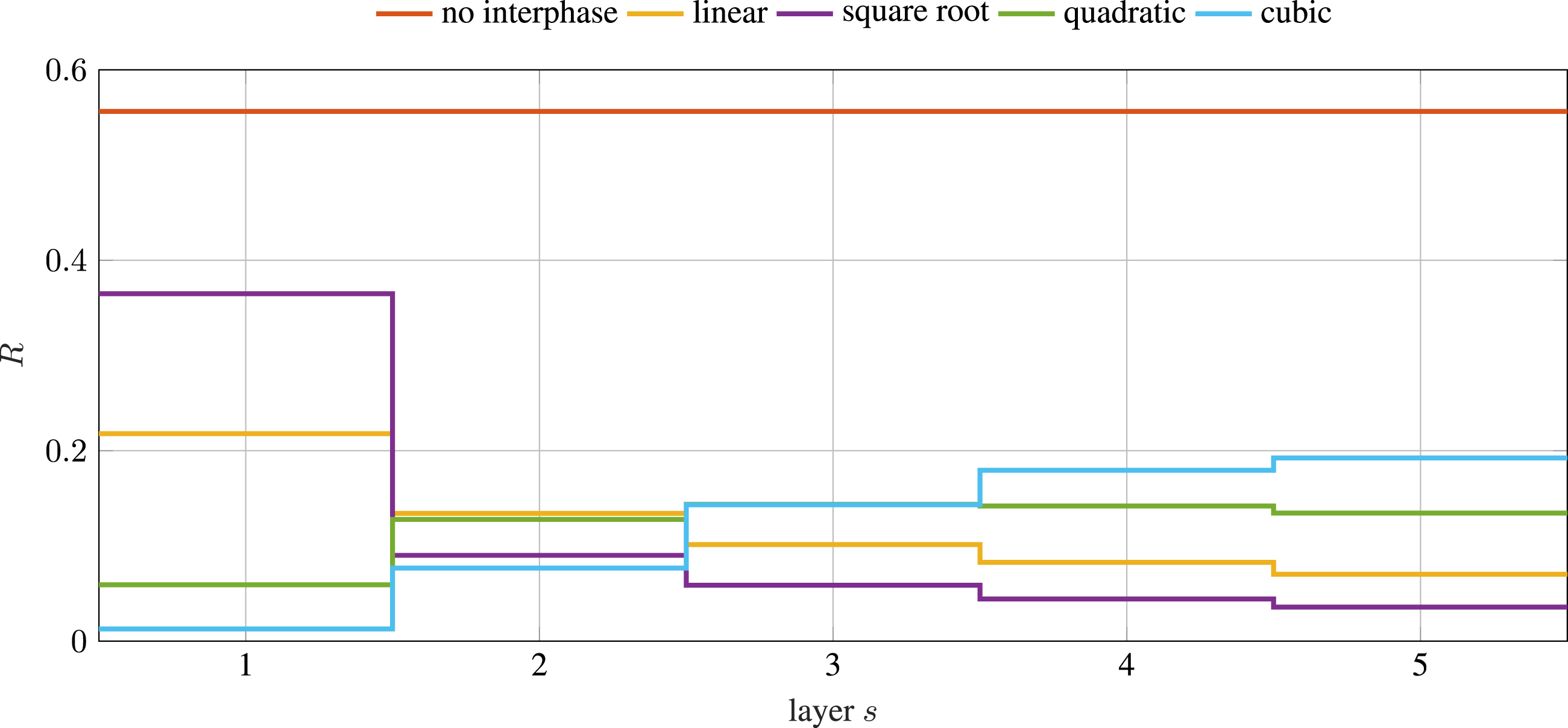
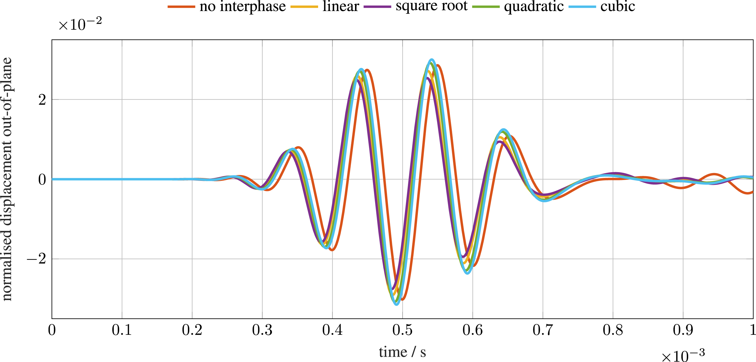
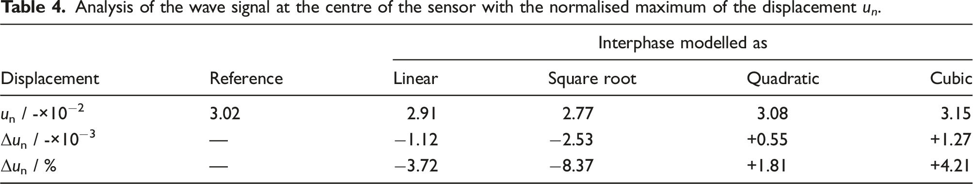
The transmitted wave packages in the centre of the sensor, which are shown in Figure 9 and in Figure 7(b), do not show a huge advantage due to any of the interphases, as was the case with the reflected wave packages. However, it is noticeable in Figure 9 that the wave signals are in phase. This is because the distance travelled by the wave packages is identical. This is different from the reflection. In Figure 6(b), a phase-shifted signal can be seen, which results from the wave being reflected earlier at the interphase due to the larger diameter and thus covering less distance than the signal reflected by the sensor (with the smaller diameter). Furthermore, the evaluation of the maxima of the enveloping interphases as presented in Table 4 shows that only the quadratic and cubic interphases have a small advantage, specifically an amplified amplitude. On the other hand, the interphases with a linear and square root gradient show a reduction of the wave signal, that is, a deterioration. Analogous to the reflection behaviour, the evaluation of the wave signal in the centre of the sensor also shows that a gentle increase of the impedance in the first steps leads to an improved transmission behaviour. Here, the phenomena can be explained equally as a result of the transmission coefficient, which starts optimally for the cubic and quadratic interphases and only deteriorates with increasing interphase steps. In general, it can be seen that the interphase has a relatively minimal impact on the transmission behaviour. Considering the approximations used, especially that of the wave velocity in equation (14), which has an error of Normalised displacement u of the structure at the centre of the sensor in the time domain at 10 kHz. Analysis of the wave signal at the centre of the sensor with the normalised maximum of the displacement u
n
.
6. Summary and conclusions
In this contribution, a mechanical model was developed which allows for a numerical feasibility study regarding a planar gradient acoustic impedance matching between a sensor and its surrounding host material. As an example, a circular sensor glass housing was embedded in a homogeneous epoxy resin matrix. The gradient acoustic impedance matching was performed by adding tungsten particles to the epoxy resin matrix. By doing so, an interphase between the sensor glass housing and the embedding host can be designed, where the design parameter is the content of tungsten particles which varies in the radial direction with respect to the sensor. Several models regarding the radial distribution of the tungsten particle content are investigated. These models are motivated by practically achievable tungsten particle distributions. The resulting wave fields are compared to the reference case, where no interphase is at hand (i.e. no tungsten particles were added). It is shown that a distribution which can be approximated by a quadratic or a cubic function yields (i) reduced reflections from the sensor and (ii) an amplification of the signal measured by the sensor. The reason for this behaviour is that the low impedance jump at the beginning of the interphase results in a lower reflection coefficient and thus significantly reduces the first reflection. Within the interphase, the wave propagates from step to step with less energy losses, due to the low reflection at the transitions, which results in an increased signal at the sensor. The impedance jumps within the interphase in turn lead to reflections, so that part of the wave signal is reflected between the interphase steps and leaves the interphase only with little energy, thus – as a research hypothesis – avoiding the occurrence of a new source pole. With respect to SHM applications, this concept of artificial interphases paves the way for reducing false-detections of damage in terms of type, position, and size. This increases the reliability of deductions from SHM measurements and may prevent false-detections of damage. The approach also retains its validity for other material combinations of sensor and matrix as long as these materials have homogeneous and isotropic material properties. An implementation of interphases for impedance matching in heterogeneous, anisotropic materials such as fibre-reinforced plastics in FML is not possible without further investigations, since interactions between materials and wave field must be expected here which makes the problem much more complex. The particle material should either have a higher impedance than the material with the highest impedance or a lower impedance than the material with the lowest impedance to enable impedance matching. For a new material combination of sensor and matrix, only the parameter φmax must be recalculated and adapted to the new material combination to determine the interphase properties. The other material parameters can be calculated accordingly. For cases where the deviation of the impedance between sensor and matrix becomes large (larger than in this work), it is to be expected that the impedance matching as presented leads to worse results. However, this problem can be counteracted by increasing the number of steps without reducing the step width. The numerical model can be refined by increasing the number of steps which in the limit leads to a continuous model. Additionally, other numerical functions describing the radial distribution of the design variable can be investigated. However, the experimental implementation must be possible.
Although the general applicability is numerically proven, an experimental validation is necessary and will be conducted as a next step. The authors are aware that experimental implementation experiences a couple of challenges, for example, sedimentation and agglomeration of the particles, the requirement of an in-plane gradient, while gradients along the thickness direction are state of the art, as well as the need for higher particle contents in the interphase layer adjacent to the sensor which increases the complexity of manufacturing as methods such as centrifugal processes are difficult to apply. All these challenges will be addressed in a future experimental work and are neglected in the present work.
Based on this work, an implementation of the numerically determined and thus error-free wave-number must be carried out in subsequent work. This step is important, especially for higher excitation frequencies found in SHM up to 250 kHz. Furthermore, the model must be improved concerning the number of steps so that continuous impedance matching can take place. For this purpose, the influence of the tungsten particles must also be investigated more closely and, if necessary, more suitable homogenisation approaches must be used. As a next step, both the mechanical model and the experimental implementation will be extended to the design of artificial interphases in laminate structures. Hence, future investigations should take into account the locally varying material parameters (Rauter, 2021; Weber and Zimmermann, 2021), too. However, this leads to an increased effort in performing the numerical studies and/or in evaluating experimental data. Thus, a study of the (numerical) cost-effectiveness (Weber and Reuter, 2017) should be performed in advance.
Footnotes
Acknowledgement
The author(s) expressly acknowledge the financial support of the research work on this article within the Research Unit FOR3022 – Ultrasonic Monitoring of Fibre Metal Laminates Using Integrated Sensors – by the German Research Foundation (Deutsche Forschungsgemeinschaft (DFG)).
Declaration of conflicting interests
The author(s) declared no potential conflicts of interest with respect to the research, authorship, and/or publication of this article.
Funding
The author(s) disclosed receipt of the following financial support for the research, authorship, and/or publication of this article: This work was supported by the Deutsche Forschungsgemeinschaft; FOR3022.
Correction (April 2023):
Article updated to correct the article type to Research article.