
Abstract
Acoustic liners take an essential role in the noise attenuation in ducts. In this work, the multimodal method based on the finite-difference method is extended to predict the acoustic field in a rectangular duct lined with a finite porous material and validated by the experiment. A modified immersed interface method is developed for the air–porous interface problem in the extended multimodal method without flow. When the flow exists, the treatments of the air–porous interface problem and the continuity of pressure between the wall and liner are also given. Three ways of describing the porous liner using the surface impedance at normal incidence named normal impedance, the surface impedance at grazing incidence named shear impedance and a cavity filled with the equivalent fluid of porous material are introduced. The comparison among the three ways reveals that the extended method of treating liners using a cavity filled with the equivalent fluid is more accurate for the acoustic evaluation of porous liners. The analysis finds that the shear impedance can reasonably present the influence of porous material during the comparisons of transmission loss curves of the liners with different lengths and depths at different Mach numbers. In most cases, the prediction by the shear impedance is closer to that simulated by the cavity filled with porous material than the normal impedance. Normal impedance is hardly utilized to describe the porous material and is only reliable when the cavity is very short and deep.
1. Introduction
Duct noise problems are common in many industrial fields, such as aircraft engine noise, electronic cooling fan noise, automotive exhaust mufflers and ventilation duct noise problems (Jones and Howerton, 2016; Ji and Huber, 2022; Lahiri and Bake, 2017; Sun et al., 2022b; Xiao et al., 2022). For passive noise reduction of a duct, it is general to apply acoustic treatments to the wall of the duct. Typically, a variety of liners, such as perforate-over-honeycomb core liners and metal foam (Lu et al., 2016; Schiller et al., 2017; Yang and Cheng, 2016), can be buried in the inner side of the engine nacelle to achieve sound attenuation. The perforate-over-honeycomb core liner, which effectively reduces tonal noise and is widely studied (Spillere et al., 2020; Yang et al., 2018; Zhang et al., 2021), is a typical locally reacting liner. The porous liner is one kind of non-locally reacting liner, which has outstanding attenuation performance from the mid- to high-frequency range with a proper design. Many researchers studied the acoustic performance of the porous liner in the duct.
Currently, porous liners can be modelled using the normal impedance (Bauer, 1977; Dhief et al., 2020; Othmani et al., 2015; Troian et al., 2017; Tuasikal et al., 2021; Tounsi, 2022) or a cavity with the equivalent fluid (Hou, 2020; Jiang and Wang, 2020; Li et al., 2019; Satcunanathan et al., 2019; Qiu et al., 2020a; Qiu et al., 2020b). However, the normal impedance is not sufficient to characterize the acoustic behaviour of a porous liner. Considering the sound wave in the duct is grazing incident to the surface of the liner, shear impedance is proposed in this work to describe the porous liner well in most cases in which the normal impedance is invalid. This will be demonstrated in this study. When the porous liner is treated as a cavity with the equivalent fluid, several methods are developed for the evaluation of the liner in the open literature. For the study of the acoustic characteristics of an infinite cylindrical duct with infinite foam, analytical methods are proposed (Li et al., 2019; Qiu et al., 2020a). Further, considering the effect of the finite foam on transmission loss (TL) in a cylindrical duct, the mode-matching method was utilized to deal with the discontinuity between the wall and liner, and the eigenvalues were achieved by the root-finding algorithms (Nennig et al., 2010). To avoid root-finding procedures, the Chebyshev collocation method (Chan et al., 2017) and the finite element method (FEM) (Jiang and Wang, 2020) were used to get the eigenvalues numerically. These two methods were validated by the comparison with the full FEM simulation but not experimentally on porous liners.
The noise problem of the rectangular duct lined with the porous material is also common in the ventilation system or the liner acoustic test rig for cancelling the unexpected noise in the duct. In response to the rectangular duct with a finite foam, the frequency-domain FEM (Schiller et al., 2017) and the time-domain approach (Alomar et al., 2021; Hou, 2020; Satcunanathan et al., 2019) are presented for simulations. For the acoustic problem in the rectangular duct lined with a finite foam, a suitable analytic or semi-analytic approach in the frequency domain also needs to be studied further for its fast, convenient and parameterization flexibility. In this work, the multimodal method (Dai, 2020; Dai and Aurégan, 2018) is extended for the prediction of the acoustic field, which can provide the modes at once without the iterative procedures to find roots. For the porous liner, the current multimodal method based on the finite-difference method has not been extended to handle this discontinuous media problem, and the existing immersed interface method is not suitable for the generalized eigenvalue problem (Colnago et al., 2020; LeVeque and Li, 1994; Lin et al., 2019). To extend the multimodal method, a modified immersed interface method is developed to treat the air–porous interface without flow. When the flow exists, the extended multimodal method is also presented, which is validated and can accurately predict the acoustic field of a rectangular duct with a finite non-locally reacting liner.
This paper is organized as follows. Section 2 presents the theory of the rectangular duct acoustic field study. In Section 3, the experimental devices and setup are illustrated. Section 4 shows the comparison between the simulations and experiments for the melamine foam liner. Three ways, the surface impedance at normal incidence named NI, the surface impedance at grazing incidence named SI and an actual cavity filled with the equivalent fluid of porous material named CWPM, are compared with the experimental results. The effectiveness of three ways is discussed. Finally, conclusions are drawn in Section 5.
2. Theoretical modelling
In this section, three ways of describing porous material are presented. When a porous liner is described using the CWPM, the treatment of the air–porous interface is proposed. Without flow, the modified immersed interface method is derived to get the coefficients of discrete points near the interface. When the flow exists, an auxiliary equation is introduced for the interface problem. As the liner is described using the impedance, the calculations of the NI and SI are presented. Finally, the mode-matching method is utilized to achieve the coefficients of the acoustic modes.
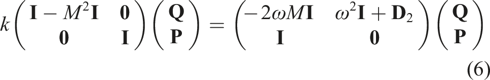
2.1. Generalized eigenvalue problem
The rectangular duct of height H is considered, which is lined by a porous material of length Sketch of a rectangular duct with a porous material. The liner is flush-mounted at the bottom of region II.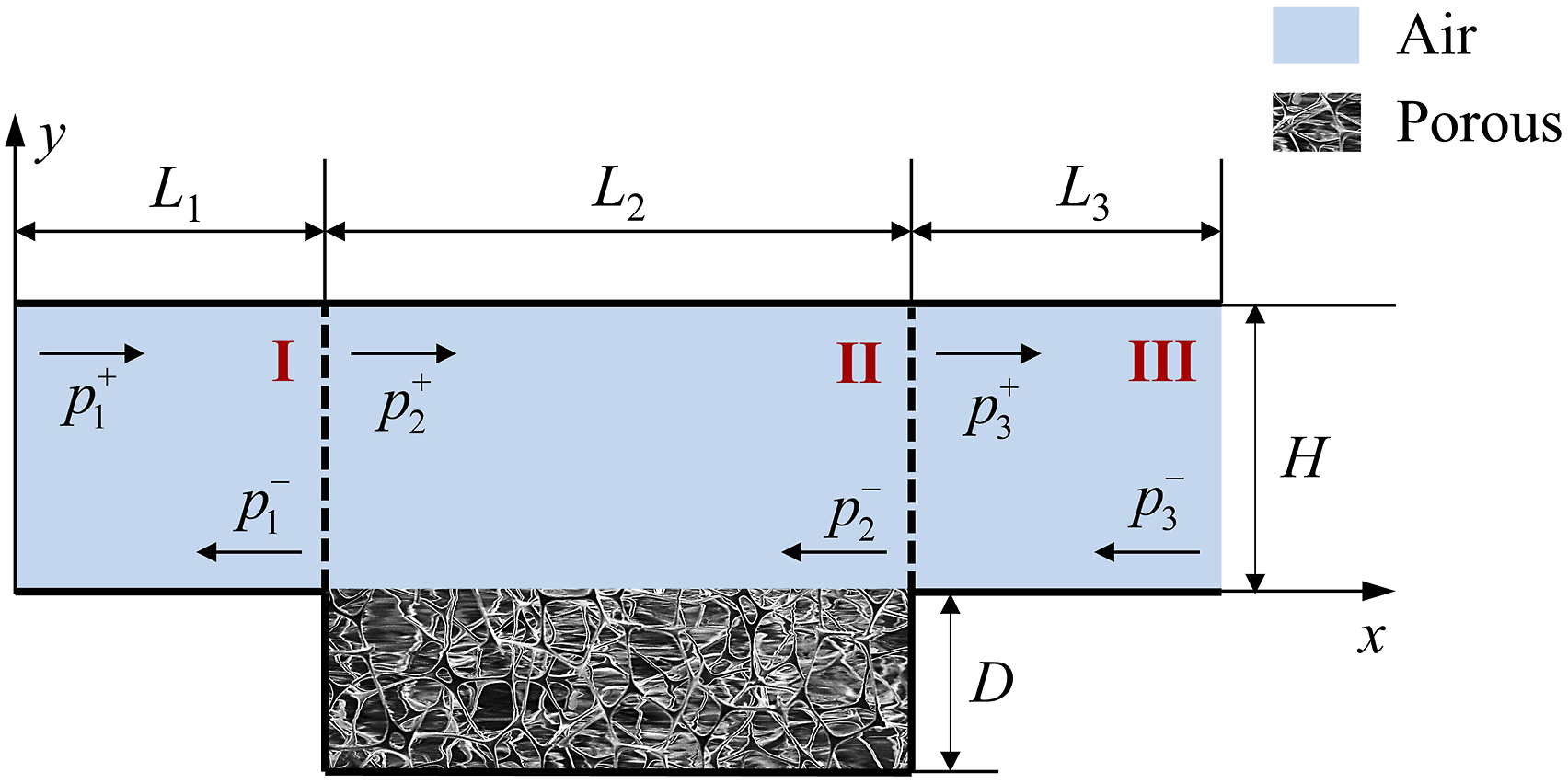
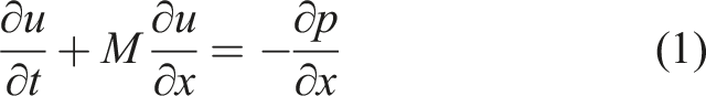
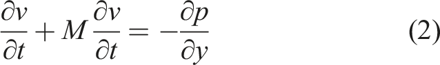
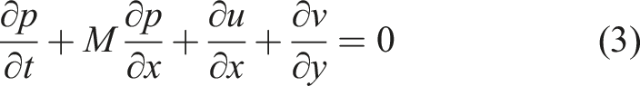
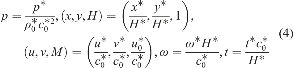
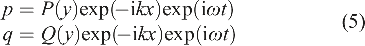
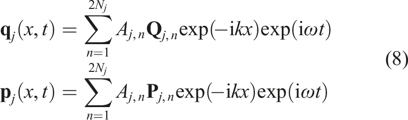
Substituting equation (5) into equations (1), (2) and (3), these equations can be rewritten using only the variables P and Q by eliminating the velocity perturbation. These equations are discretized by taking, respectively,
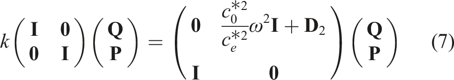
2.2. Air–porous interface problem
During simulations using the CWPM, the information between the two mediums needs to be transmitted. Here, a modified immersed interface method is derived for information transmission in the absence of the flow. When the flow exists, the auxiliary equation is introduced for the interface problem.
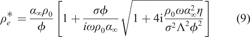
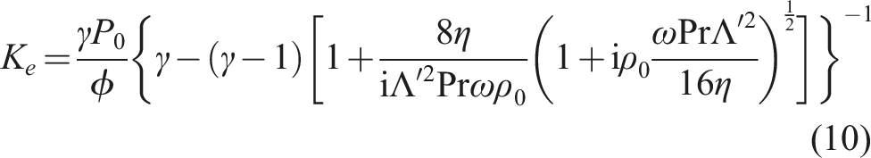
Firstly, the modified immersed interface method is derived. The equivalent fluid properties are calculated by the Johnson–Champoux–Allard (JCA) model (Champoux and Allard, 1991; Johnson et al., 1987). The JCA model assumes that the frame of porous material is rigid. In the JCA model, five porous parameters: porosity

The key is to represent the second derivative of Sketch of points in the air and porous material.
According to the condition
Therefore, the coefficients are expressed by
Similarly, the coefficients of
The information can be transmitted by modifying the matrix
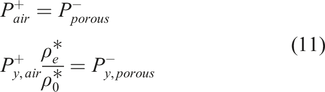
Next, if the flow exists and a perforated sheet is included on the air–porous interface, the continuity of the pressure and particle displacement yields
2.3. Modelling of the porous liner using the surface impedance
Except for being described by the CWPM, porous liners can also be described by the impedance boundary concept, as shown in Figure 3. The impedance is derived assuming that the length of porous material is infinite. The interaction between the acoustic fields in two mediums is neglected during the simulation by the impedance, which can be considered during the simulation by the CWPM. However, the implementation modelling by the impedance is much more convenient than that by the CWPM, in which no air–porous interface problem is treated. In this subsection, the process of modelling the porous liner using the surface impedance will be introduced. Three ways of modelling the porous material: SI, NI and CWPM.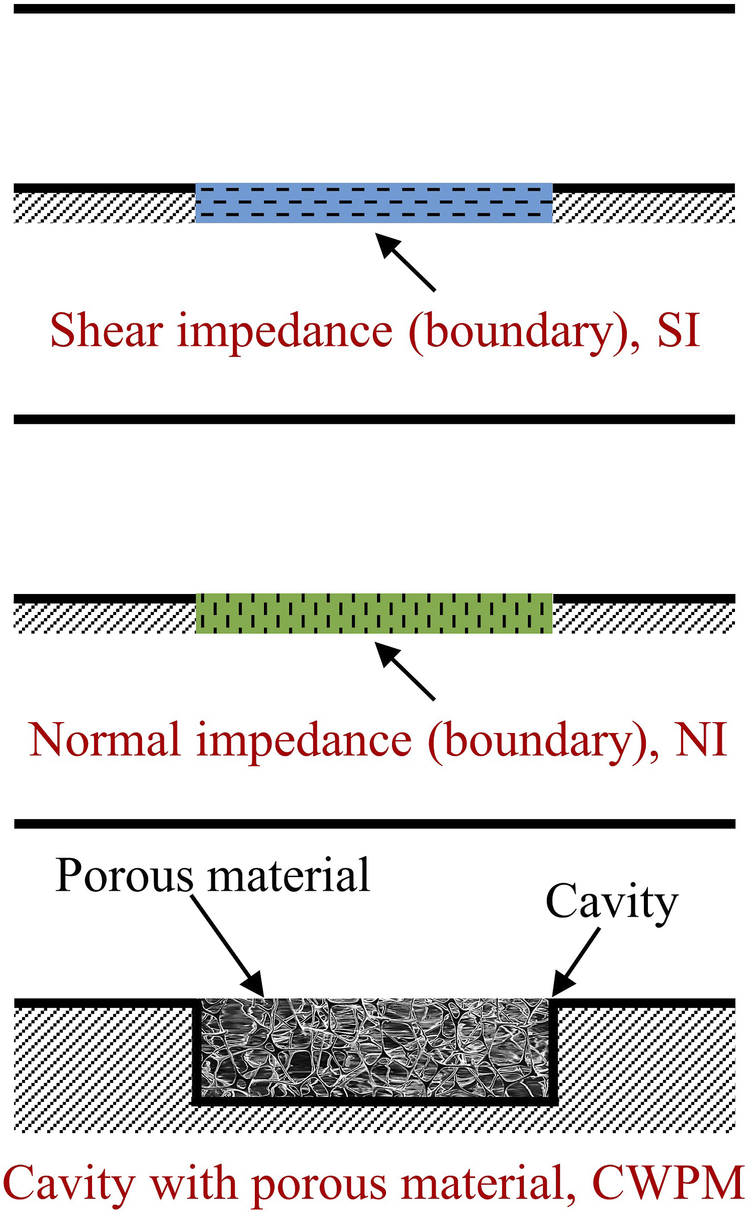
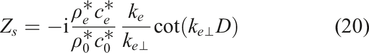
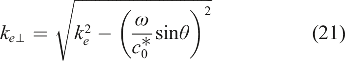
The wavenumber of porous material A sketch of the sound wave incident to the surface of the porous material.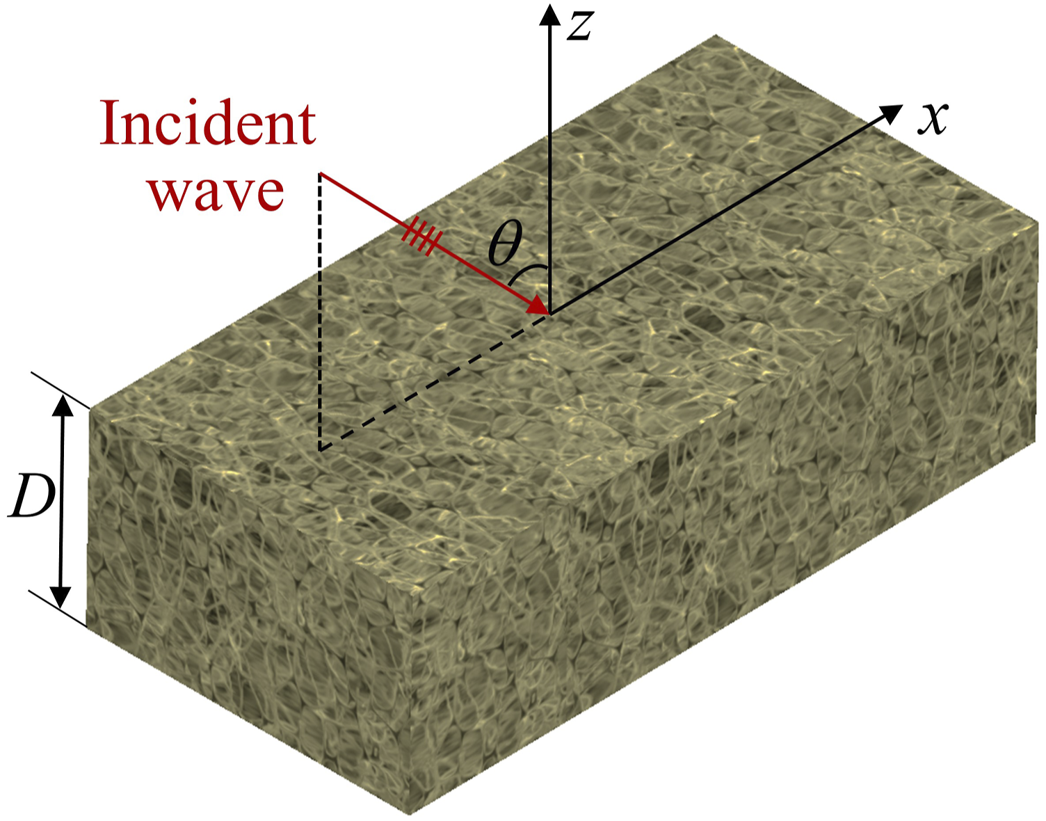
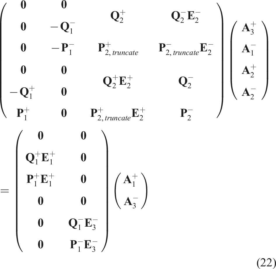
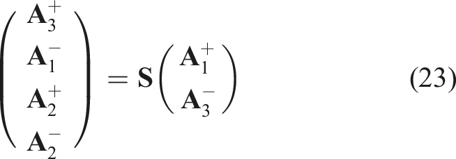
2.4. Mode-matching method
The continuity of pressure and the quantity
3. The acoustic experiment of the duct with the liner
The experiment was conducted in the impedance tube at Northwestern Polytechnical University. The duct has a square cross-section of 0.05 m 2D sketch, 3D model and photograph of the impedance tube.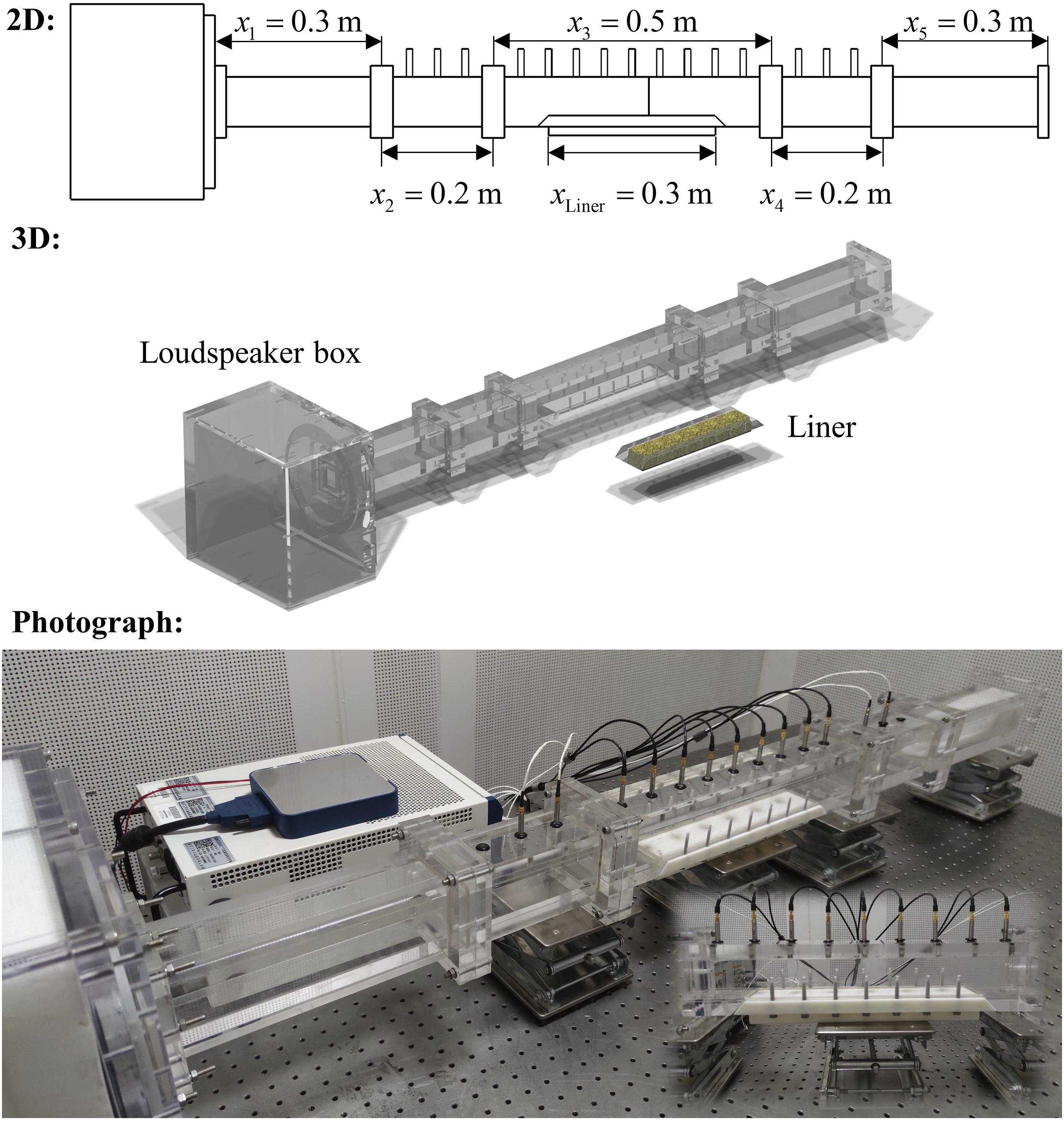
4. Results and discussion
In this section, the experiment was performed in a duct lined with melamine foam to validate the effectiveness of three ways. The melamine foam has a length of 0.3 m, a width of 0.05 m and a depth of 0.03 m, as shown in Figure 6. By measuring the microstructure given in Figure 6, the average fibre diameter and gap can be obtained, which are 5 The photograph and microstructure of the melamine foam. The five JCA parameters of melamine foam.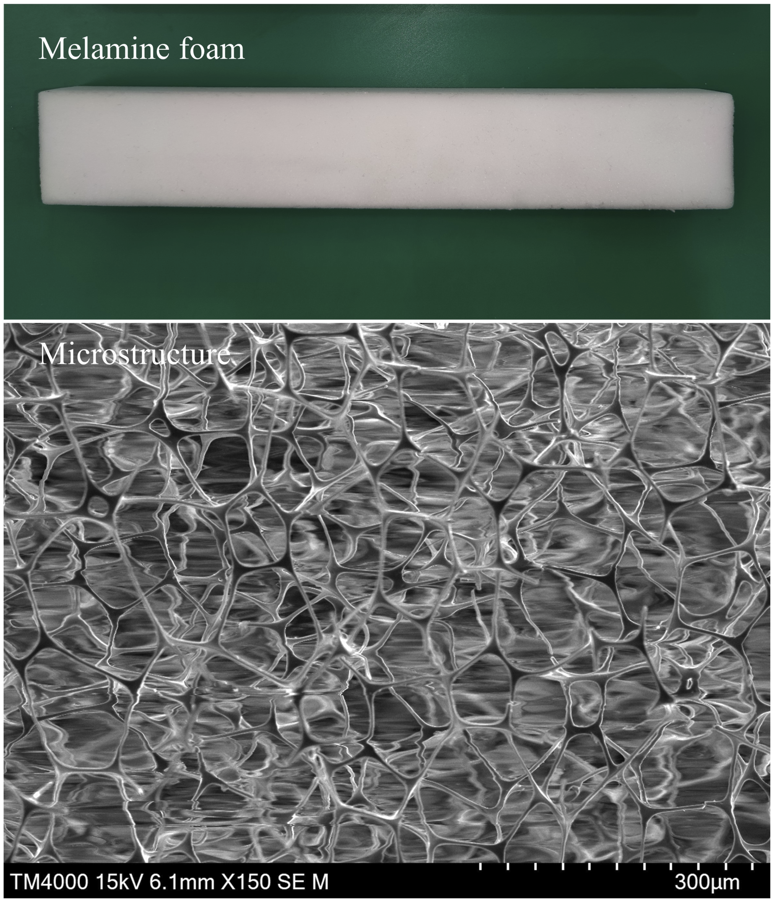

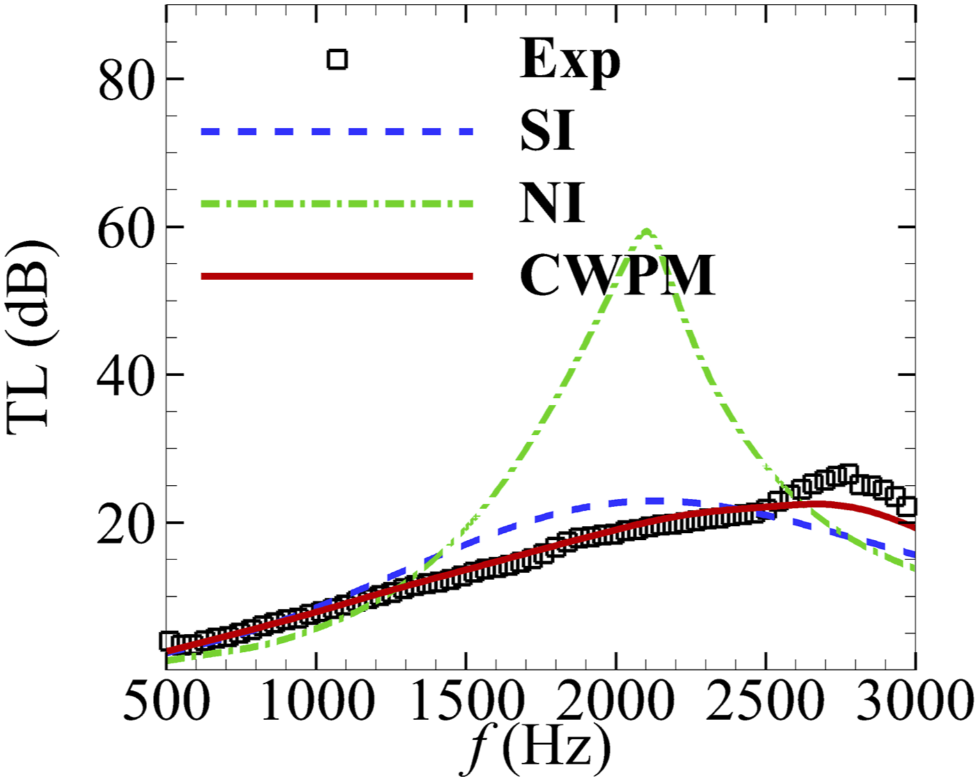
Figure 7 shows the comparisons between the three predictions and the experimental results at frequencies ranging from 500 Hz to 3000 Hz in the step of 500 Hz. The simulations using the CWPM are in pretty good agreement with the measured sound pressure level (SPL) along the central line of the upper wall, both in terms of the tendency of the attenuation change and the standing wave patterns. SI can be used to evaluate the sound attenuation performance of the liner, in which the slope of the attenuation can be approximately captured, but the details of the tendencies of the SPL are ignored. The way of using the NI is unsuitable for this case. The acoustic field can hardly be predicted by the NI, especially at 2000 Hz. The predicted TL curves versus frequency are also compared with the experimental result, as shown in Figure 8. The measured TL curve is well predicted by the CWPM, especially below 2500 Hz. In this case, the predictions by the CWPM have excellent agreement with the measurements. SI can predict approximately the main trends observed in the experiment with some discrepancies in detail. It is hard to use the NI to evaluate the performance of the liner. Sound pressure level along the central line of the upper wall at different frequencies when M = 0, L = 0.3 m and D = 0.03 m. A comparison between the predicted transmission loss curves and experimental data, where L = 0.3 m and D = 0.03 m.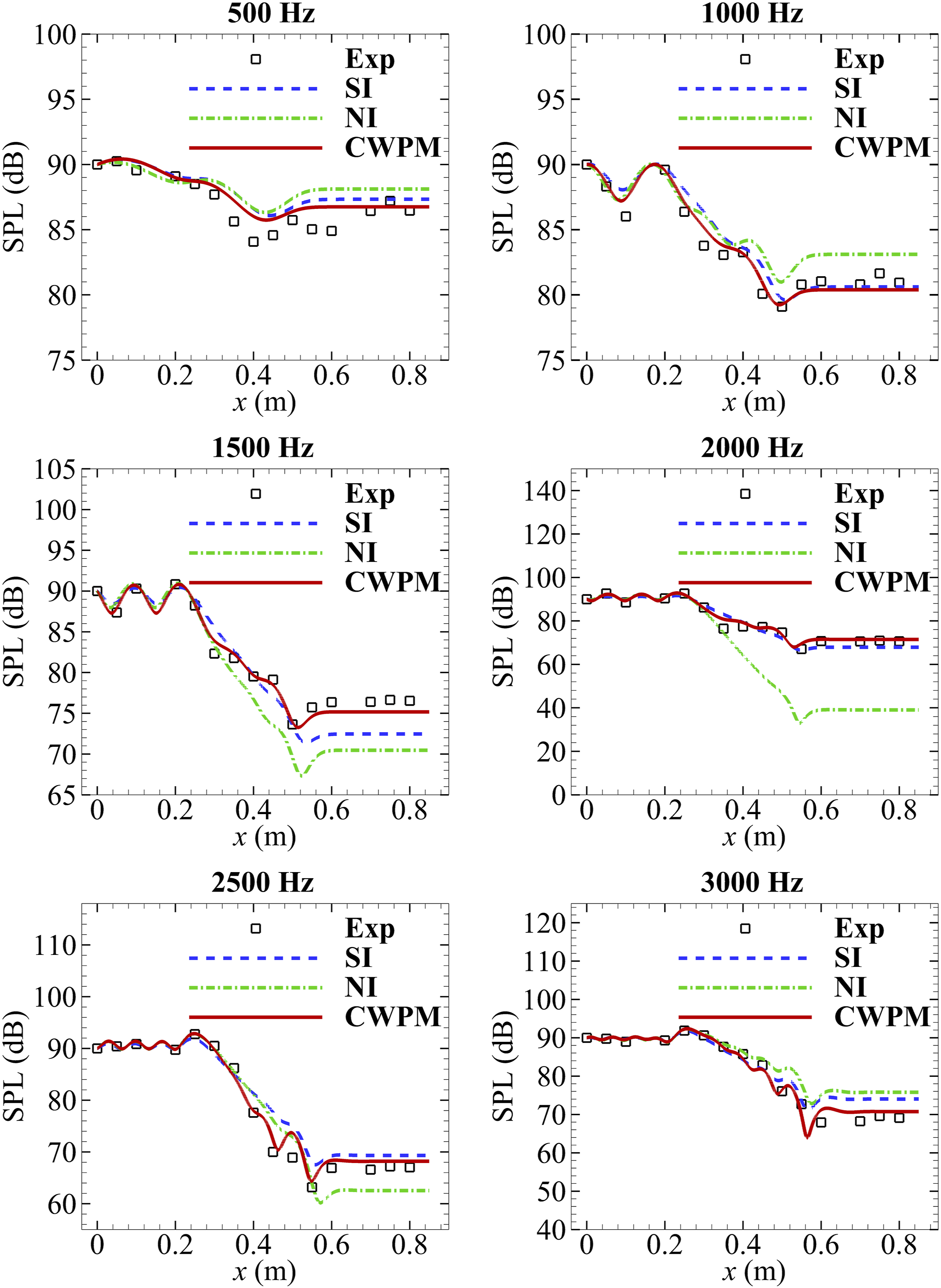
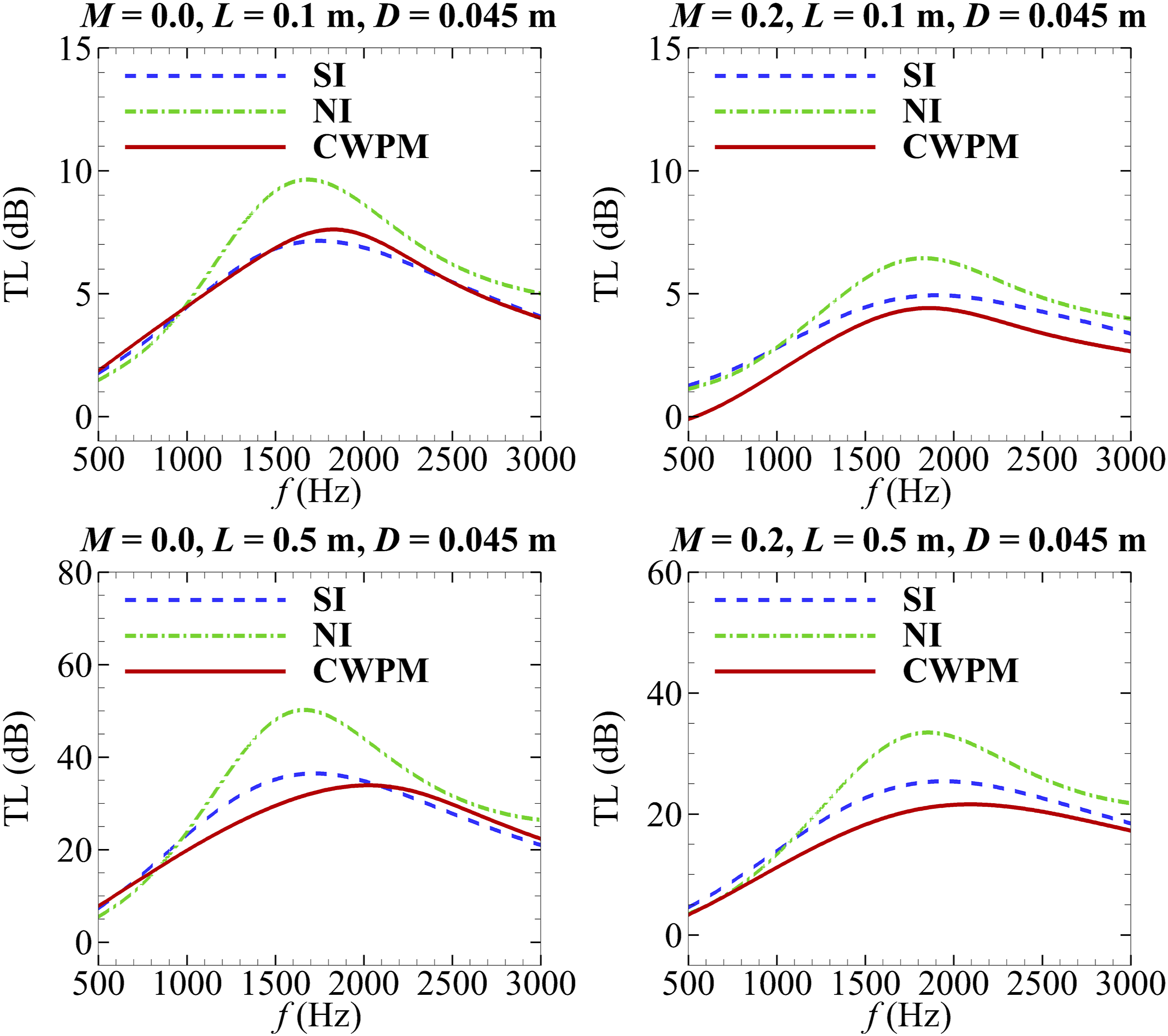
For further evaluation of the predictive behaviour of the three ways, the TL curves of melamine foams having different depths at M = 0 and M = 0.2 are given in Figure 9. The length is fixed at 0.3 m and the depths are 0.015 m, 0.03 m and 0.045 m, respectively. In Figure 9, the predicted TL curve by the SI is closer to that simulated by the CWPM than the NI, regardless of the presence or absence of flow. There are discrepancies between results simulated by the SI and the CWPM, but the largest discrepancy for all the liners is around 5 dB. The largest discrepancy using the NI reaches 40 dB. As the liner deepens, the differences between the NI and the CWPM predictions become smaller, but the discrepancy is larger than that between the SI and the CWPM predictions. Figure 10 presents the TL curves of melamine foams having different lengths at M = 0 and M = 0.2. The depth is fixed at 0.045 m and the lengths are 0.1 m and 0.5 m, respectively. Similarly, in Figure 10, the TL curves predicted by the SI are close to that simulated by the CWPM. When the liner becomes longer and deeper, differences between the NI and the CWPM predictions will become smaller but still larger than that between the SI and the CWPM predictions. The NI can only be reliable when the cavity is very short and deep. Transmission loss curves of the liners having different depths. Transmission loss curves of the liners having different lengths.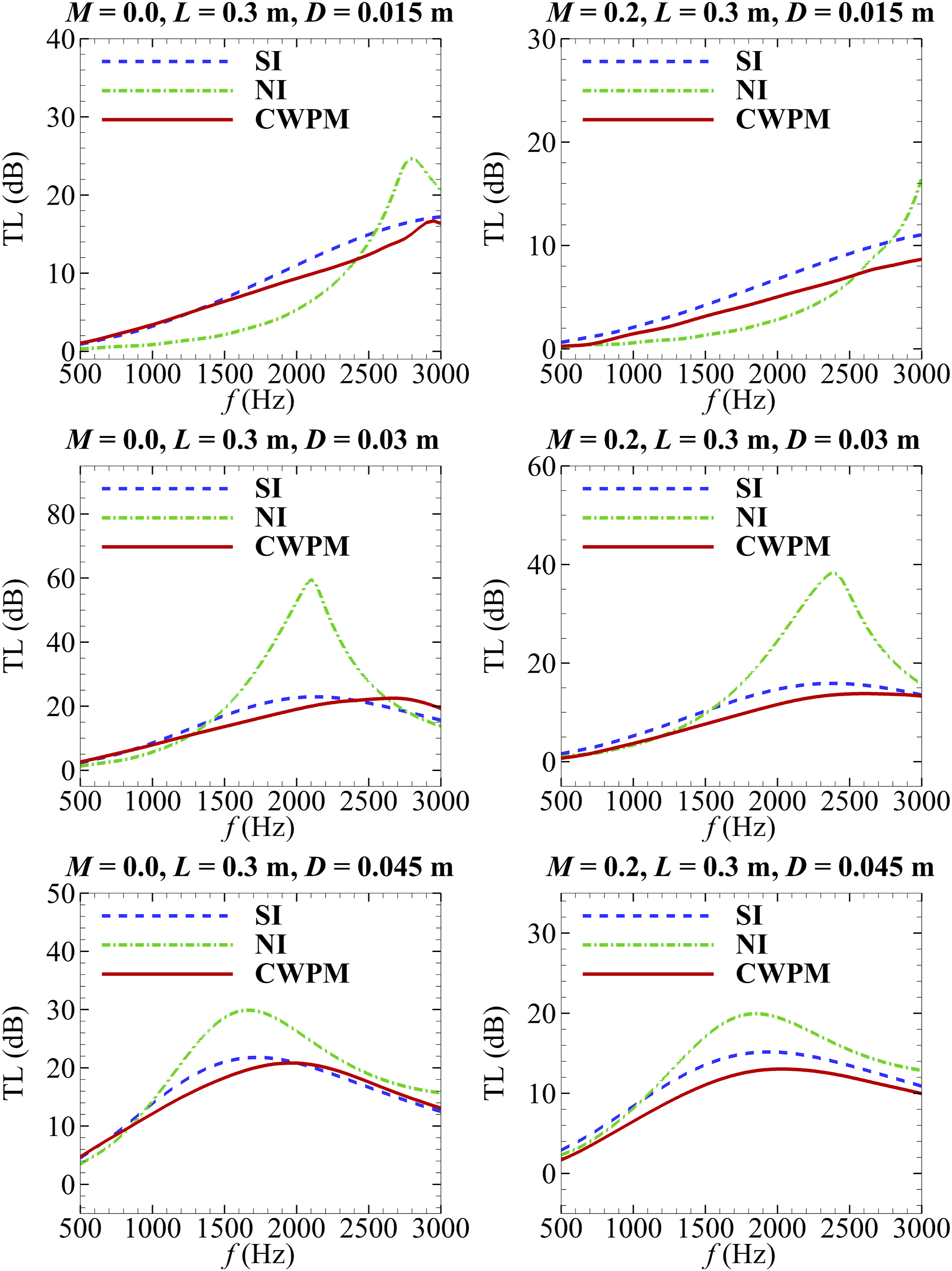
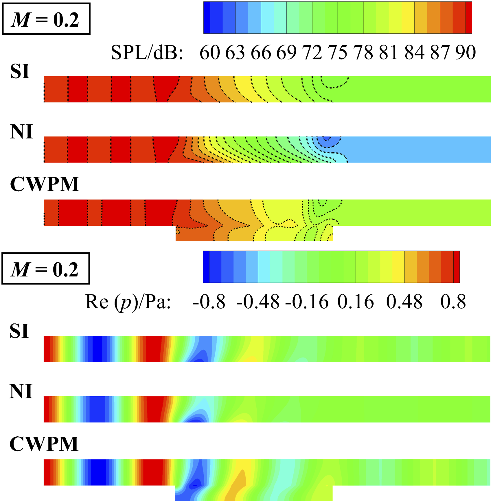
To compare the difference among the three ways better, Figure 11 shows the SPL and Sound pressure level and Sound pressure level and 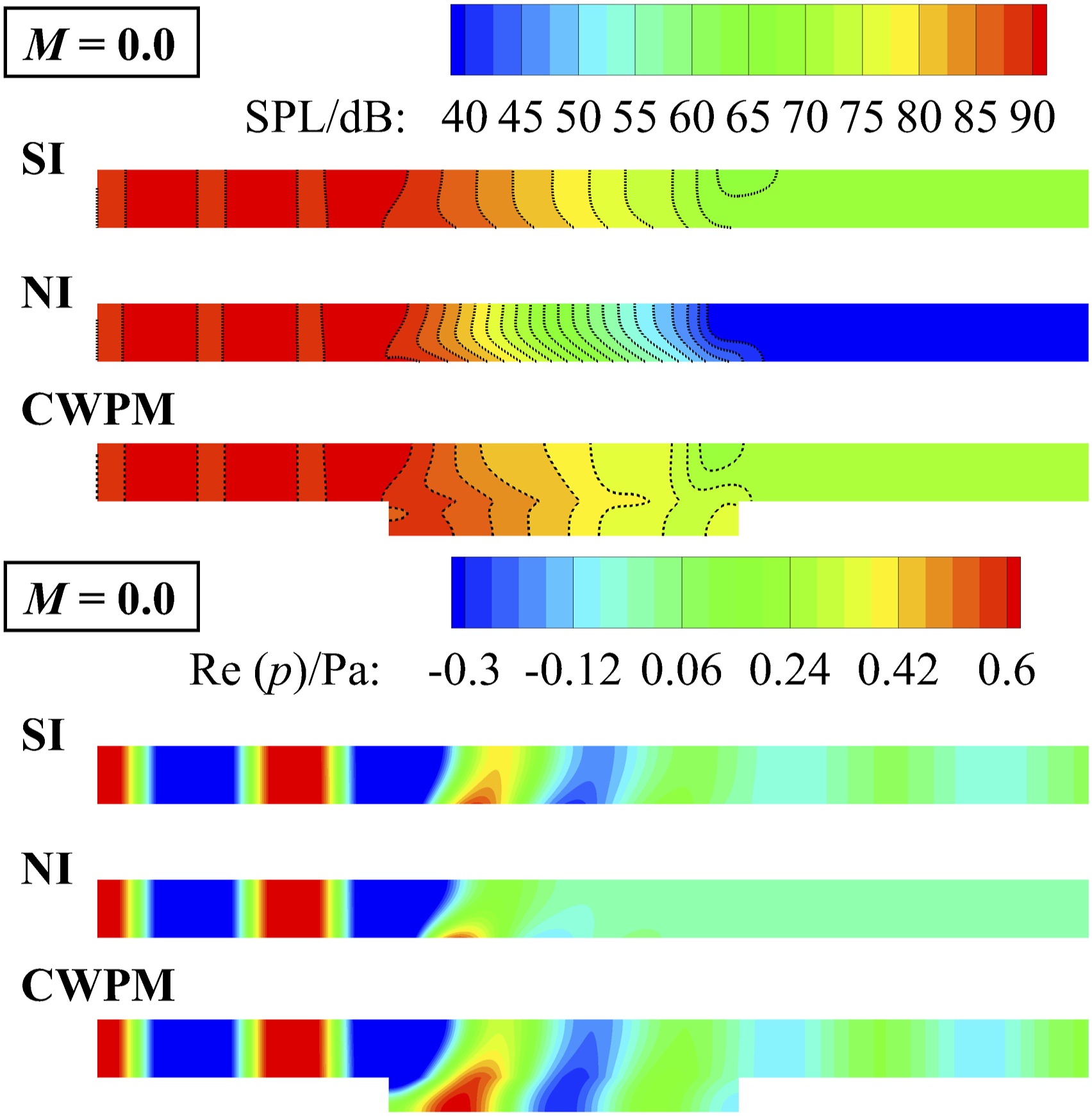
5. Conclusions
In this study, the extended multimodal method for acoustic field prediction in a rectangular duct lined with a finite porous material is proposed in the frequency domain, which is validated by the experiment. Three ways of describing the porous material, respectively, using the NI, SI and CWPM are compared with the experiment. The applicability of the impedance boundary method is discussed. The following conclusions can be drawn: (1) In the extended multimodal method, the immersed interface method is modified for the generalized eigenvalue problem to treat the air–porous interface in the absence of the flow. When the flow exists, the auxiliary equation is added to deal with the interface. This extended method using the CWPM can more accurately predict the acoustic field in the duct with a porous liner than the multimodal method utilizing the NI or the SI. It provides the best agreement with measurements. (2) According to the comparison with the experiment, SI can reasonably present the attenuation tendency of the acoustic field of the duct with a porous liner. During the comparisons of TL curves of the liners having different lengths and depths at different Mach numbers, the prediction by the SI is closer to that simulated by the CWPM than the NI. The implementation of modelling by the SI is much more convenient than that by the CWPM, in which no air–porous interface problem needs to be treated. (3) NI can hardly be utilized to evaluate the sound attenuation performance of a porous liner, except that the liner is very narrow and deep. Differences between the NI and CWPM predictions will become smaller when the porous liner becomes shorter and deeper.
Supplemental Material
Supplemental Material - An investigation on the modelling of a finite porous liner for the sound propagation in a rectangular duct
Supplemental material for an investigation on the modelling of a finite porous liner for the sound propagation in a rectangular duct by Xiang Song, Jing jian Xu, Tian yue Yuan, Wen hao Sun, Dan Sui, He ye Xiao and Jie Zhou in Journal of Vibration and Control
Footnotes
Declaration of conflicting interests
The author(s) declared no potential conflicts of interest with respect to the research, authorship, and/or publication of this article.
Funding
The author(s) disclosed receipt of the following financial support for the research, authorship, and/or publication of this article: This work was supported by the National Natural Science Foundation of China [grant number 12072277]; the Fundamental Research Funds for the Central Universities of China [grant number G2022KY0608] and the funds from Key Laboratory of Aeroacoustics, AVIC Aerodynamics Research Institute [grant number XFX20220204].
Supplemental Material
Supplement material for this article is available online.
References
Supplementary Material
Please find the following supplemental material available below.
For Open Access articles published under a Creative Commons License, all supplemental material carries the same license as the article it is associated with.
For non-Open Access articles published, all supplemental material carries a non-exclusive license, and permission requests for re-use of supplemental material or any part of supplemental material shall be sent directly to the copyright owner as specified in the copyright notice associated with the article.