
Abstract
In this paper, the scattering and vibration isolation of elastic waves from the open trench are analyzed and discussed in the time domain using the scaled boundary finite element method (SBFEM). Based on the theory of soil-structure interaction, the site with an open trench is decomposed into a near-field system and an infinite far-field system. The quadtree domain decomposition technique is employed for SBFEM mesh discretization of the near-field. The far-field is rigorously modeled by the displacement unit impulse response matrix. The obliquely plane elastic wave from the far-field is converted into a traction force acting on the near/far-field boundary. The time-space domain numerical model is established for elastic wave propagation in half-space with an open trench. Finally, through numerical examples to verify the effectiveness of the method of this paper, and parametric analyze the effect law of the incidence angle and the trench depth, etc., on the vibration isolation performance.
Keywords
1. Introduction
The man-made ground vibration including transportation, machinery equipment, and engineering construction is spread around through the ground, bringing adverse effects to the life of nearby residents, the safety of the surrounding buildings, and the accuracy of precision instruments. The ground vibration control has become one of the hot topics to be solved in the field of geotechnical engineering.
At present, the most common mitigation for the vibration propagation is the installation of wave barriers between the vibration source and the protected building, which include open and filled trench (Adam and Estorff, 2005; Ahmad and Al-Hussaini, 1991; Andersen and Nielsen, 2005; Beskos et al., 1986; Çelebi et al., 2009; Emad and Manolis, 1985; Herbut, 2020; Murillo et al., 2009; Saikia and Das, 2014; Shrivastava and Rao, 2002; Ulgen and Toygar, 2015; Woods, 1968; Xu et al., 2015; Zhou et al., 2021), row piles (Gao et al., 2006; Kattis et al., 1999), and wave impeding block (Gao et al., 2017; Ma et al., 2019). The open trench is considered to be the most efficient barrier for vibration isolation and is widely used in vibration isolation engineering. Up to now, the research methods on the vibration isolation performance of open trench mainly include experimental studies, numerical simulation, and theoretical analysis. In terms of experiments, Woods (1968) is the first to study the vibration isolation of the open trench in the near and far-fields through a series of in-situ tests in the field and proposes to use the amplitude reduction ratio to evaluate the vibration isolation effect of the barrier; Ahmad and Al-Hussaini (1991) study the size and location of the open and filled trench through field tests, which provide some guidelines for vibration isolation design; (Çelebi et al., 2009; Murillo et al., 2009; Ulgen and Toygar, 2015) experimentally study the effects of parameters such as load frequency, soil parameters, and barrier sizes on the vibration isolation behavior of open and filled trench under simple harmonic loads; In terms of numerical simulations, Saikia and Das (2014) analyze numerically the open trench vibration isolation problem under simple harmonic loads using the finite element Plaxis2D; Shrivastava and Rao (2002) investigate the effect of open and filled trench geometries on the isolation effect of Rayleigh waves by means of a three-dimensional finite element model. Emad and Manolis (1985) analyze the vibration isolation effect of arbitrarily shaped two-dimensional shallow trench based on the boundary element method, which finds that the shallow trench can reduce the foundation disturbance by 25% only in the medium frequency range, and trench geometry has less effect on the vibration isolation. Adam and von Estorff (2005); Andersen and Nielsen (2005) analyze the effect of trench geometry and location on the vibration isolation effect under train load by the coupled boundary element-finite element method. Herbut (2020) research on the vibration isolation effect of the open trench by finite element method from the view of reducing the vertical and horizontal components of vibration, the vibration isolation effect of the open trench on horizontal displacement is better than that on vertical displacement. Zhou et al. (2022) present a novel wave barrier (open trench-wave impedance block barrier) by considering the respective advantages of the open trench and wave impedance block. The novel wave barrier has a better isolation effect for the vibration in the low-frequency range through finite element analysis. In terms of theoretical analysis based on the theory of complex functions and conformal mapping methods, Xu et al. (2015) present a theoretical solution for single-trench for plane wave isolation and Zhou et al. (2021) give a theoretical solution for multiple-trench for plane SH wave isolation.
From the above, the research on the vibration isolation of open trench is mainly focused on the relevant analysis under different loads and different geological conditions. Artificial vibration waves consist mainly of body waves (S-wave and P-wave) and surface waves (Rayleigh wave, etc.), and near-field vibration isolation is mainly for body waves and far-field vibration isolation is mainly for surface waves. The time-domain analysis can accurately and visually describe the action of the open trench for elastic waves; However, there are few studies on the time-domain analysis of the open trench for elastic wave isolation. The scaled boundary finite element method (SBFEM) is a numerical method developed gradually in the course of simulation studies of elastic dynamics problems in infinite domains (Song, 2018; Wolf, 2003), which has the advantages of semi-analytical, high accuracy, reduced dimensional solution, and mesh flexibility. At present, the SBFEM has many applications to the problem of elastic wave scattering in half-space (Bazyar and Song, 2017; Chen et al., 2015b; Qu et al., 2021). Based on the theory of soil-structure interaction, the site with an open trench is decomposed into a near-field system and an infinite far-field system. The near field is discretized using a quadtree mesh (Man et al., 2014). The displacement unit impulse response matrix (Chen et al., 2014) with an effective time discretization approach is utilized to allow the scattering wave to propagate to infinity without reflection. A spatial approximation by sub-structuring the far field (Chen et al., 2015a; Zhang et al., 1999) and truncating the temporal local formulation of the displacement unit impulse response matrix reduces the computational time. The incident wave input with arbitrary angle is achieved by applying an equivalent nodal force at the near/far-field interface. A numerical model of SBFEM in elastic media for elastic wave propagation is established. Finally, through numerical examples to verify the effectiveness of the method of this paper, parametric analyzes the effect law of the incidence angle and the trench depth, etc., on the vibration isolation performance.
The structure of this paper is as follows. In Section 2, the basic formulation of SBFEM for the elastic wave stimulation problem is briefly described. In Section 3, the wave input formulation for the scattering wave problem is presented. In Section 4, the effectiveness of the present method is clarified and the vibration isolation effect of the open trench for elastic waves is discussed through three numerical examples, respectively. The major conclusions drawn from this study are summarized in Section 5.
2. The scaled boundary finite element method equations
The novel SBFEM is a fundamental solution-less boundary element method based on the finite element, which needs only discrete boundary and radial strict resolution, combined with the advantages of the boundary element method and finite element method. The scaled boundary finite method is a numerical method developed in infinite domain elastic dynamics, which has been successfully applied to the numerical simulation of elastic wave propagation.
The computational model of the open trench for the elastic wave vibration isolation problem using SBFEM is shown in Figure 1. The problem domain (Figure 1(a)) is decomposed into a bounded near-field system and an infinite far-field system (Figure 1(b)). The two components are linked by the interaction force Element boundary discretization in the SBFEM.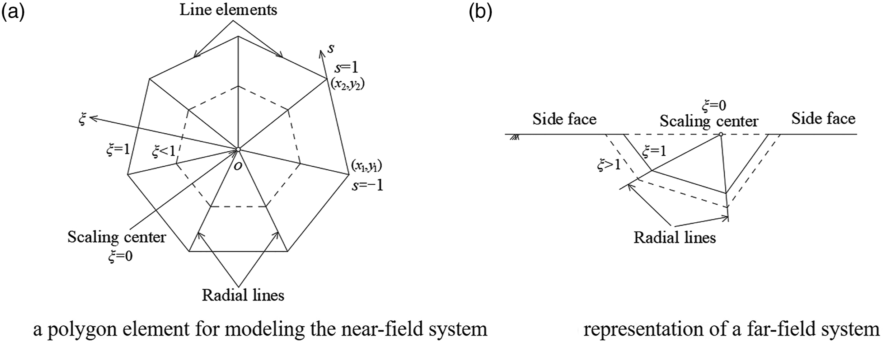
The SBFEM, unlike the FEM, first needs to discretize the circumferential boundary of the elements by numerical solution. By employing the coordinates and displacement values of the endpoints, the interpolation relationship between the coordinates and displacement of any point on the boundary can be obtained by the solution method of the one-dimensional line element in the FEM. When the line element of each boundary is solved, the nodal coordinates and displacement interpolation relations of the entire element boundary are received. Through deriving the governing equilibrium equation, the radial displacement interpolation function is solved analytically and multiplied with the circumferential boundary displacement interpolation function which yields the displacement field within the entire element.
The polygon element for modeling the near-field system using SBFEM is shown in Figure 2(a). The scale center O is established inside the polygon element, and any point on the boundary is directly visible from the scale center O to satisfy the similarity and visibility criteria of the near-field system elements. For convenience, the origin of the Cartesian coordinate system is chosen to be at the scale center. The boundaries of the polygon elements can be scaled toward the scale center to cover the entire polygon area. The scaled boundary coordinate system is defined by a radial coordinate ξ and a circumferential coordinate s. ξ runs from 0 at the scaling center to 1 on the polygon boundary for the near-field elements. For each element, s is from −1 to +1 (see Figure 2(b)). Computational model.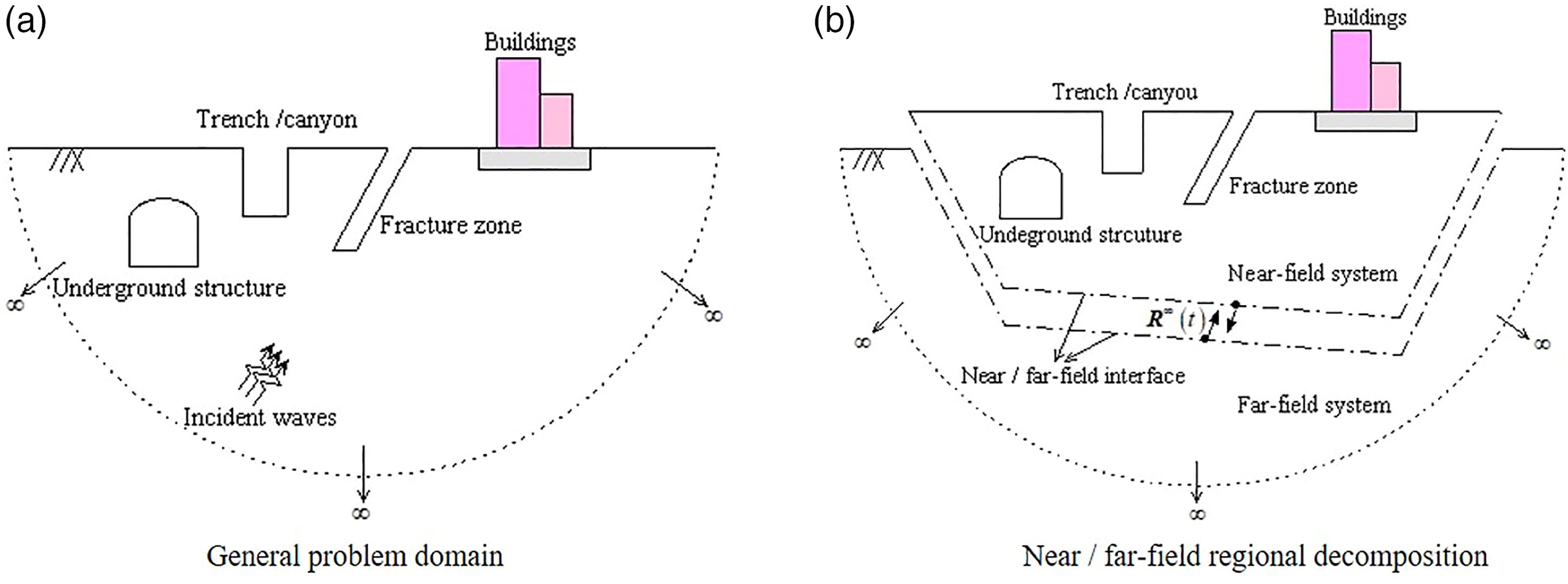
The representation of the far-field system in SBFEM is shown in Figure 2(b). Only the near-field/far-field interface is discretized. The center of scale is chosen to be on the extension of the straight free surface outside the far field. The free surfaces passing through the scaling center are treated as side faces and not discretized. ξ varies from 1 on the near/far-field interface to ∞ at infinity.
For 2D problems, the geometry of the isoparametric element is interpolated using the shape functions


Along the radial lines passing through the scaling center and a node on the boundary, the nodal displacement functions

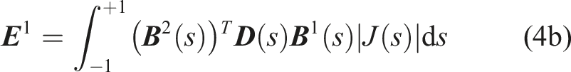
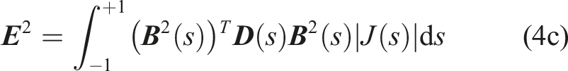
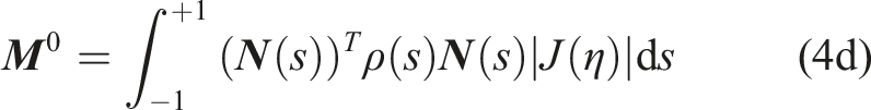
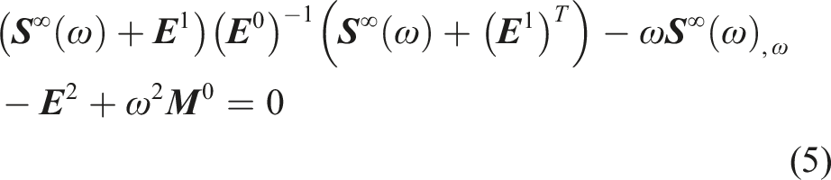
The SBFEM dynamic stiffness matrix equation for the near-field system is (Bazyar and Song, 2017; Qu et al., 2021; Wolf, 2003):
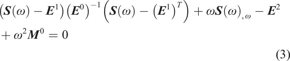
The SBFEM dynamic stiffness matrix equation for the far-field system can be similarly expressed as (Bazyar and Song, 2017; Qu et al., 2021; Wolf, 2003):
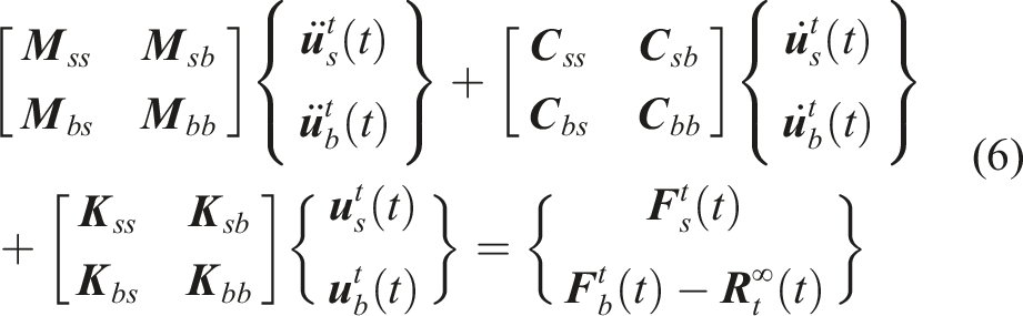
The motion equation in the time-domain for the near-field system is (Bazyar and Song, 2017; Wolf, 2003):


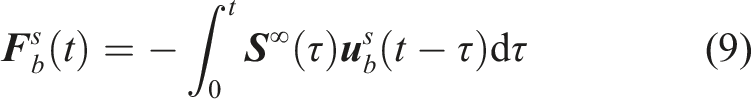
Substituting equation (9) into equation (8) further yields:
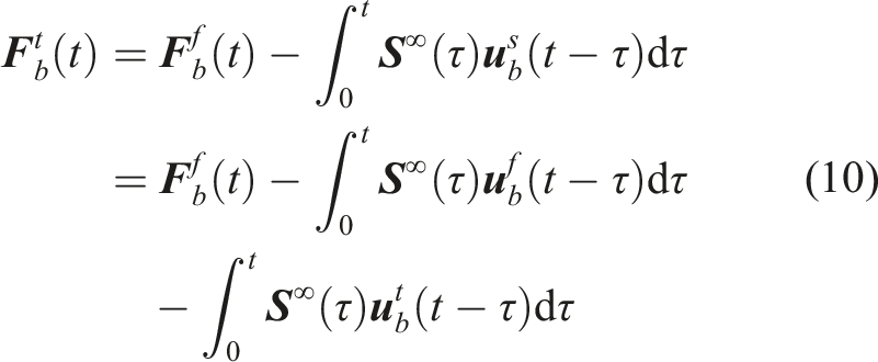
The interaction forces at the near/far field intersection can be expressed as:
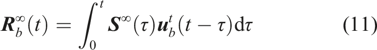
The detailed calculation of the convolution integral with respect to time in Equations. (9) ∼ (11) is described in the ref (Bazyar and Song, 2017; Chen et al., 2015b).
3. The input method of plane elastic wave
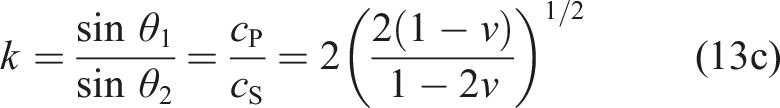
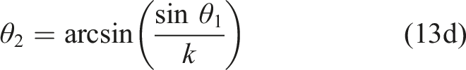
In order not to lose generality, we only consider a plane P wave incident at an angle of incidence θ1 into the half-space here, and the incident wave encountering a ground surface will generate a reflected wave P and a reflected SV wave (Graff, 2012), as shown in Figure 3. Plane P-wave input at the near/far-field interface.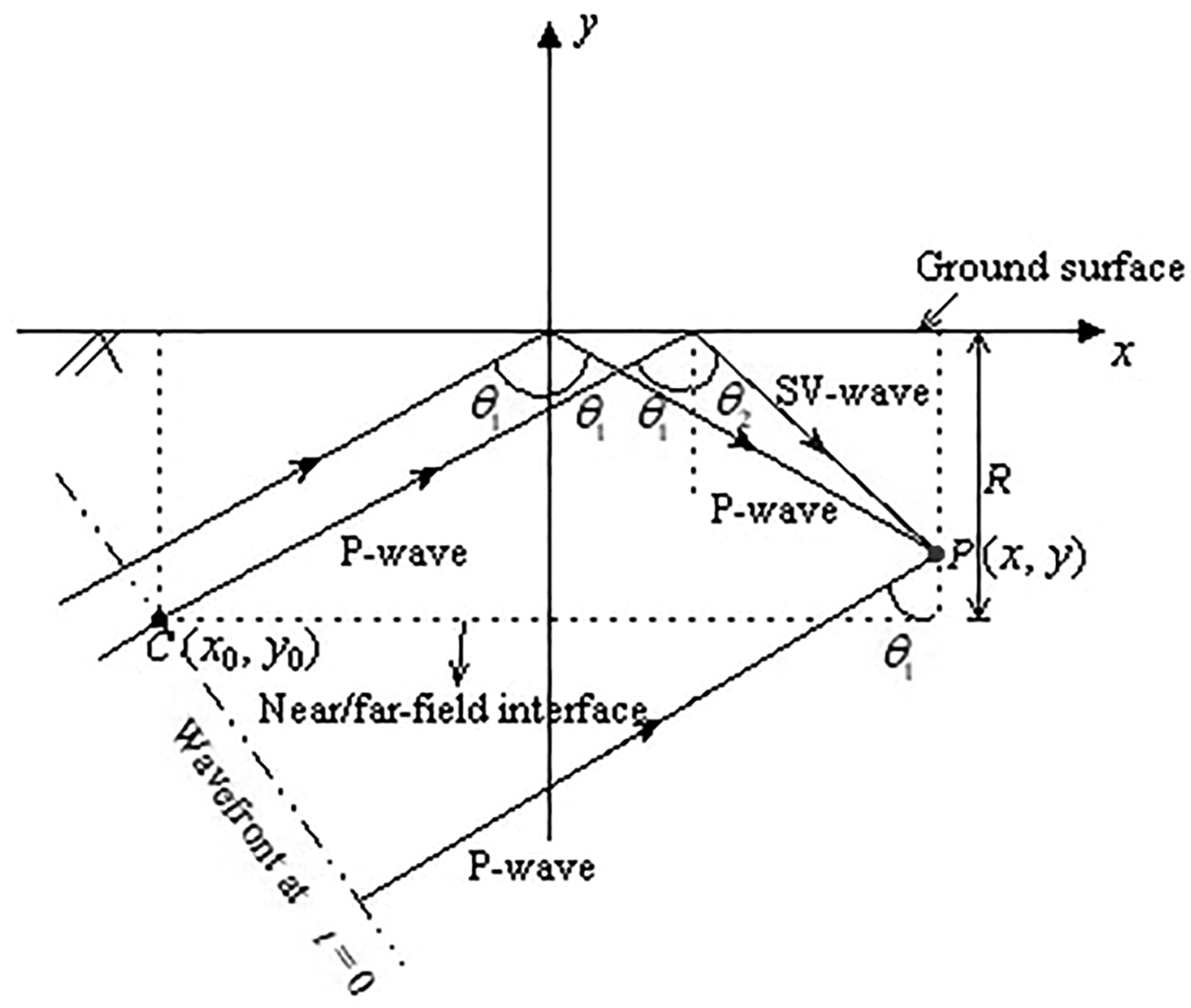
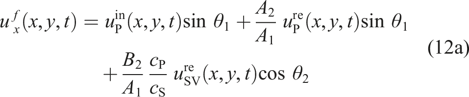
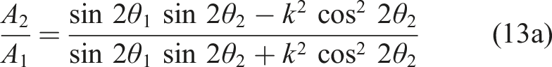
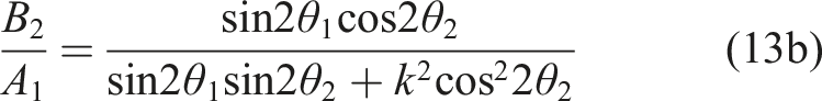
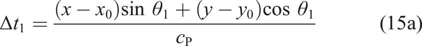
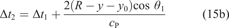
From Figure 3, the free displacement field at observation point P can be expressed as follows (Bazyar and Song, 2017; Huang et al., 2017):

Assuming that the wavefront of the incident plane P wave reaches the point C at the time t=0, the displacement components uPin(x,y,t), uPre(x,y,t), and usvre(x,y,t) of the incident P wave, reflected P wave, and reflected SV wave at the observation point P can be expressed as an excitation function with respect to the time response g(t):


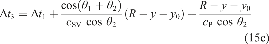
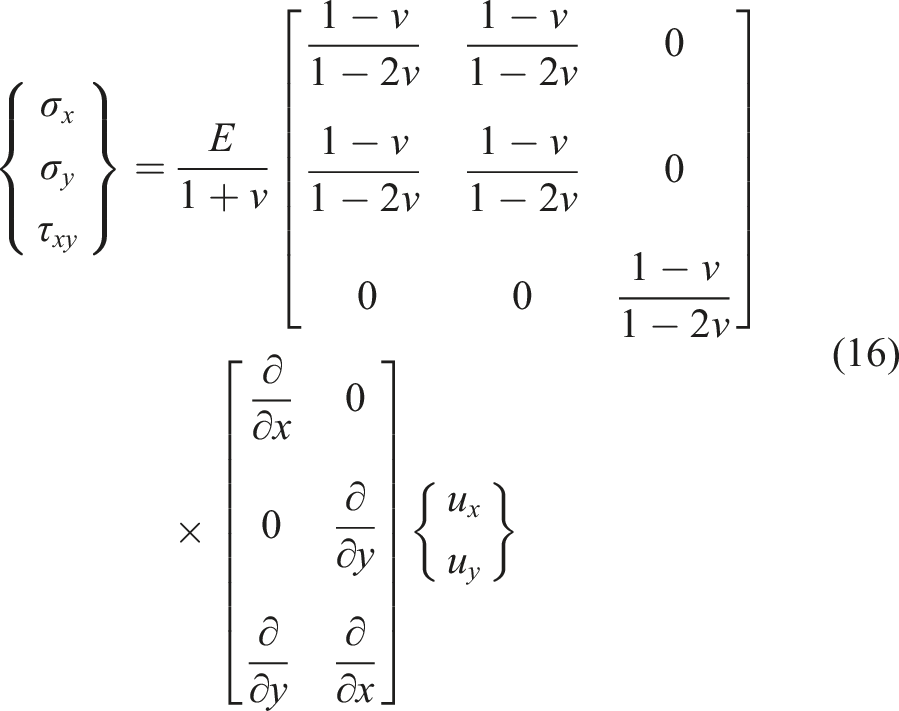
The stress–displacement relationship can be derived from Hooke’s law and geometric equation in elastic mechanics.
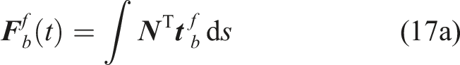
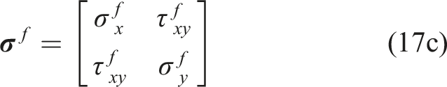
The equivalent nodal forces resulting from the free-field motion can be determined from the shape function and the unit surface traction (Bazyar and Song, 2017; Huang et al., 2017; Qu et al., 2021).

4. Numerical examples
The problem of the input of a plane P-wave in the half-space is realized by the SBFEM, and the detailed calculation steps are described in the ref (Bazyar and Song, 2017). Three numerical examples are presented in this section, the first one investigates the motion displacement of the incident plane P-wave in the free-field (without the open trench) to facilitate comparison with the analytical solution of the ref (Graff, 2012), which for verifying the results of the numerical simulation of elastic wave propagation are the same as the analytical solution. The second numerical calculation takes the scattering of elastic waves by a semi-circular canyon as an example to verify the accuracy of SBFEM in the elastic wave scattering problem. The last example considers the scattering of elastic waves by open trench (trench width is w and trench depth is h) for analyzing the vibration isolation effect of the trench on elastic waves.
4.1. Example 1
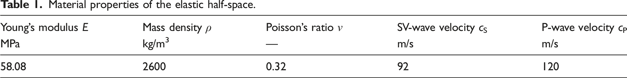
The near-field region is intercepted as a rectangle with a width of 100 m and a depth of 50 m. The grid division of the free field is shown in Figure 4, where the maximum element grid size is less than 0.625 m. This region can ensure that the incidence and reflection processes of elastic waves are observed. It is assumed that the half-space is a homogeneous isotropic elastic medium with material properties as shown in Table 1. Meshing of the free-field using quadtree. Material properties of the elastic half-space.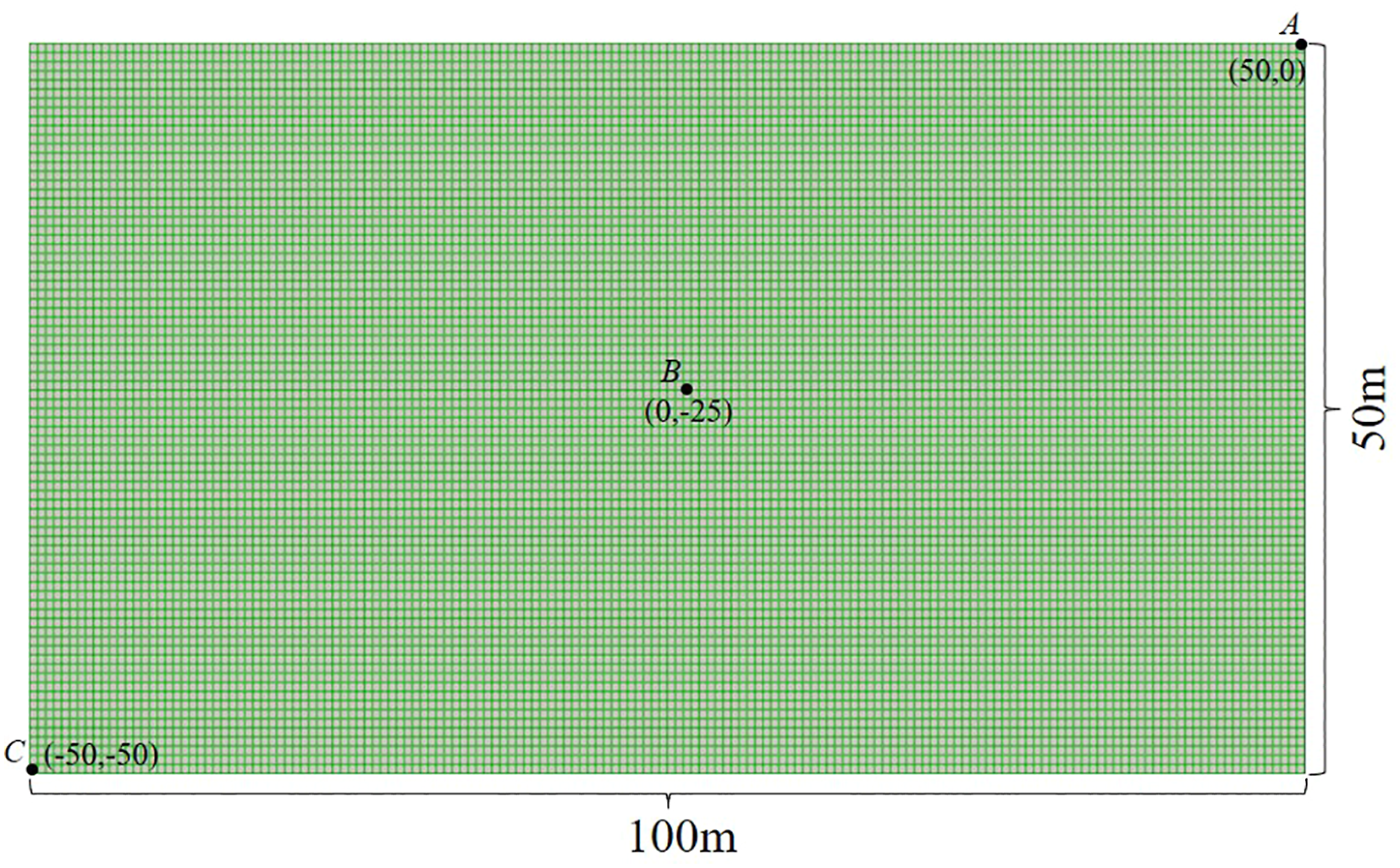
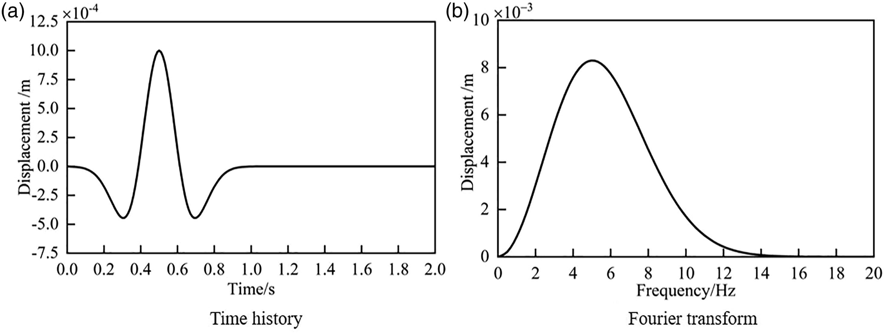
Considering the time response g(t) as a Ricker wavelet for the input of the plane P-wave. Excitation features of Ricker wavelet.
Taking the incidence angle θ1=30°, the horizontal and vertical displacement clouds in the free field under plane P-wave incidence are shown in Figure 6. It is obvious in Figure 6 that the incident angle of the plane P-wave is 30°, and the reflected P-wave and reflected SV-wave are generated when the incident wave encounters the surface boundary, and the measured values of the reflected P-wave and reflected SV-wave reflection angles are 30° and 22.5°, respectively, which are consistent with the calculated results of equation (13d). It shows that this method can effectively simulate the propagation of P-wave in the half-space. Displacement clouds in the free field under the plane P-wave incidence. Material properties of half-space with semi-circular canyon.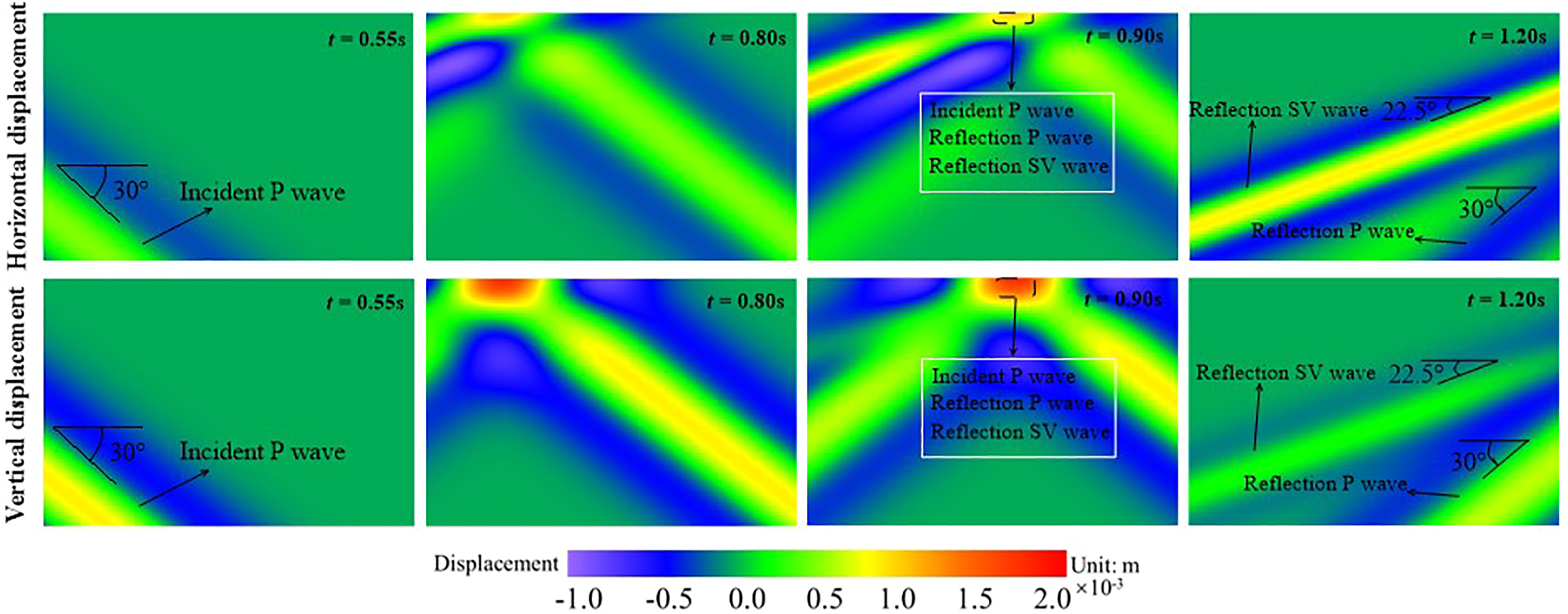
To further verify the reliability of the proposed calculation results, the time response of horizontal and vertical displacements at observation points A, B, and C (see Figure 3(a)) are plotted from Figure 7 and compared with the analytical solution(Graff, 2012). The result of this paper agrees very well with the result of ref (Graff, 2012) as can be found in Figure 7, which fully illustrates that the method of this paper can not only effectively simulate the propagation of P-wave in half- plane, but also has a very reliable calculation accuracy. Displacement responses at observation point A, B, and C in the free-field.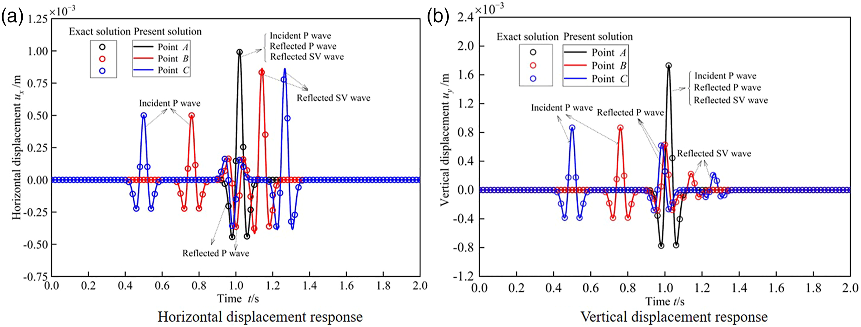
4.2. Example 2
As further verification of the accuracy of the SBFEM in modeling the elastic propagation problem in this paper, the scattering of elastic waves by semi-circular canyons with plane P-wave incidence are analyzed in this example. Considering the equation (18) as a Ricker wavelet for the input of the plane P-wave, where, A
max
=0.001m, f =9.6Hz, t0=0.5s, and λ
f
=200m. The near-field area is intercepted as a rectangle and its width is 400 m, depth is 200 m, the radius of the semi-circular canyons is R = 50 m, and the quadtree mesh discretization of the semi-circular canyons as shown in Figure 8, the maximum element grid size is less than 10m<λ
f
/10, which ensures the stability of numerical calculation. For a better comparison with the results of BEM (Wong, 1982), the dimensionless frequency is taken as Ω=2πfR/c
s
=0.5, where c
s
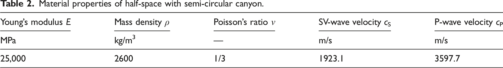
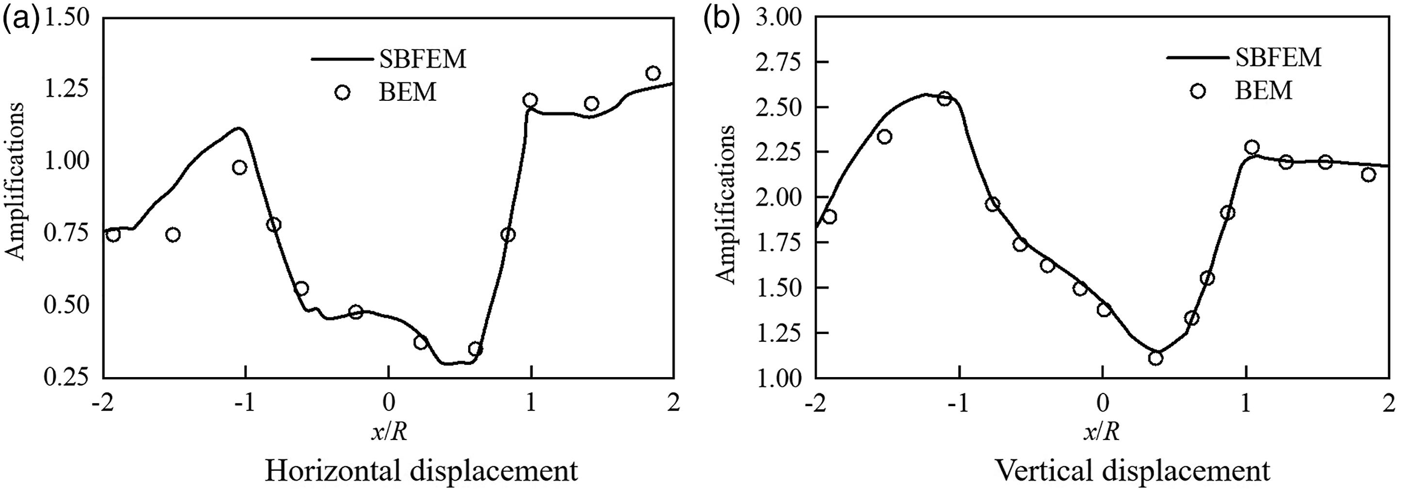
is the main shear wave velocity. The material properties of the semi-plane with semi-circular canyon are listed in Table 2. The frequency domain response obtained by the Fourier transform of the displacement time history is plotted in Figure 9, which shows the amplification of horizontal and vertical displacements of the ground surface caused by a plane P-wave (incidence angle of 30°), where the solid line is the SBFEM result and the circle is the BEM result (Wong, 1982). From Figure 9, the SBFEM results are basically in agreement with the BEM results, which illustrates the accuracy and reliability of the SBFEM in modeling the elastic propagation problem. Meshing of the near-field with the semi-circular canyons using quadtree. Displacement amplification of ground motion of semi-circular canyon.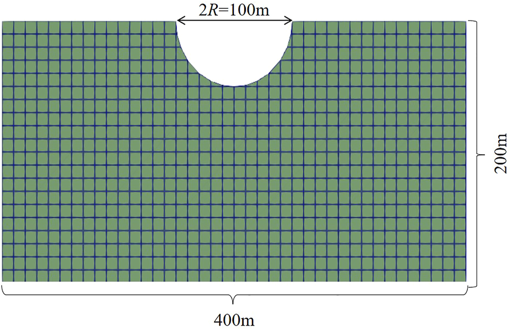
4.3. Example 3
4.3.1. Scattering of elastic waves by the open trench
Assume that the half-space is a homogeneous, isotropic elastic medium with the material properties shown in Table 1. Taking the equation (18) as a Ricker wavelet for the input of the plane P-wave, where, A
max
=0.001m, f =0.5Hz, t0=0.5s, and λ
f
=18.4m. The near-field region is intercepted as a rectangle with its width of 100 m and depth of 50 m to allow observation of the process of the action of the trench on the elastic wave. Considering the open trench width w = 1 and depth h = 8, the quadtree mesh of the near-field region is divided as shown in Figure 10, where the maximum element grid size is less than 0.625m<λ
f
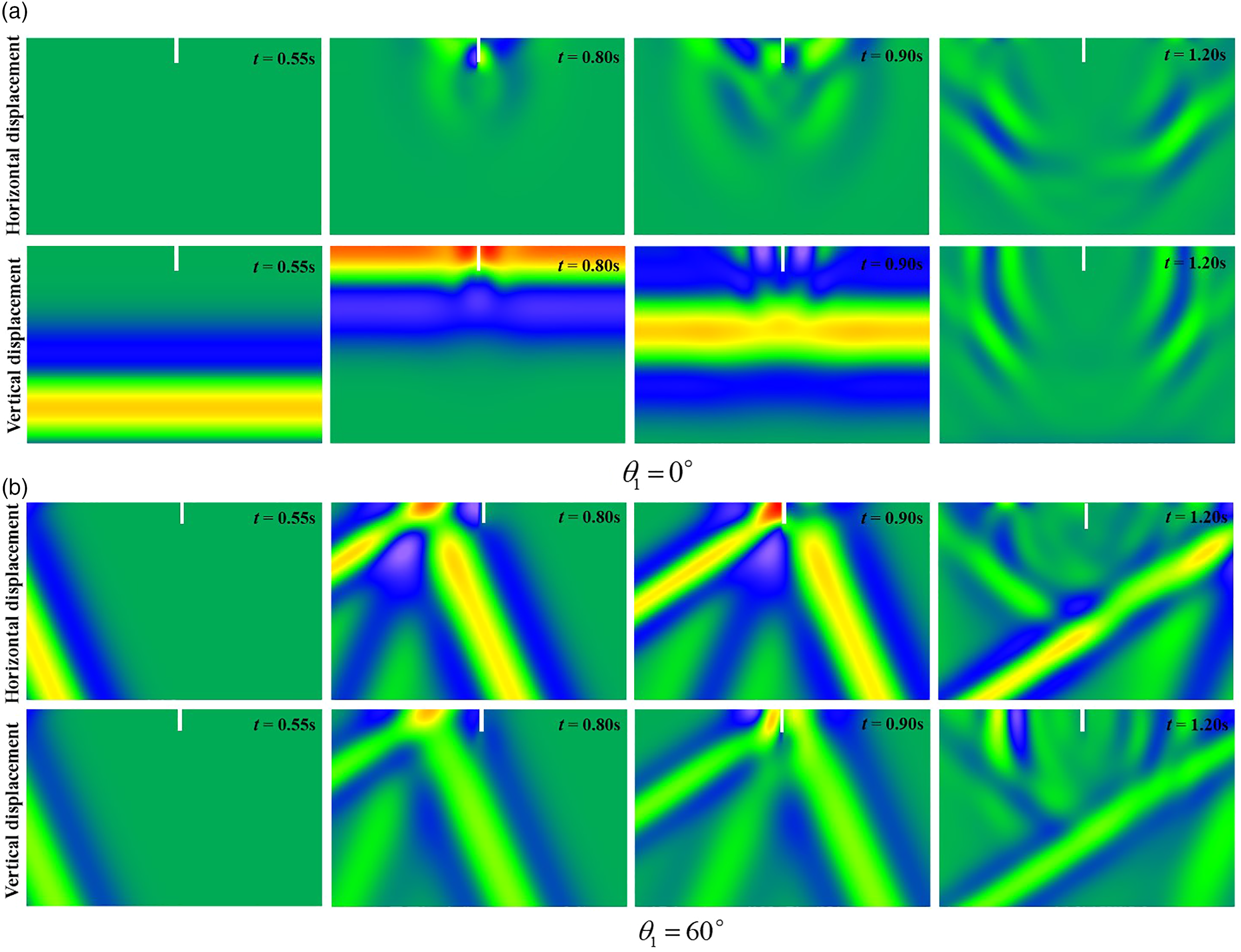
/10. The horizontal and vertical displacement response clouds are shown in Figure 11 at different times for incidence angles θ1=0° and θ1=60°, respectively. The scattered waves are generated when the elastic wave encounters the boundary of the open trench. As shown in Figure 11(a), there is only vertical displacement in the half-space (t = 0.55s) under the vertical incidence of the plane P-wave (θ1=0°). The horizontal displacement is generated in the half-space when the plane P-wave propagates further and encounters the open trench (t = 0.80s), and the vertical displacement near the open trench is obviously amplified. Therefore, it is difficult for the open trench to play a vibration isolation role when the plane P-wave is incident vertically to the surface. When the incidence angle is θ1=60° (see Figure 11(b)), the trench has an obvious barrier phenomenon for the elastic wave propagation, the displacement on the front side of the trench is amplified (t = 0.80s), and correspondingly the displacement on the back side is weakened (t = 0.90s). This phenomenon is more obvious with the increase of the incident angle, and it can also be found that the barrier effect of the trench on the horizontal displacement is obvious than that on the vertical displacement. The larger the angle of incidence, the better the vibration isolation effect of the trench. Meshing of the near-field with the open trench using quadtree. Displacement clouds of a field with an open trench under the plane P-wave incidence.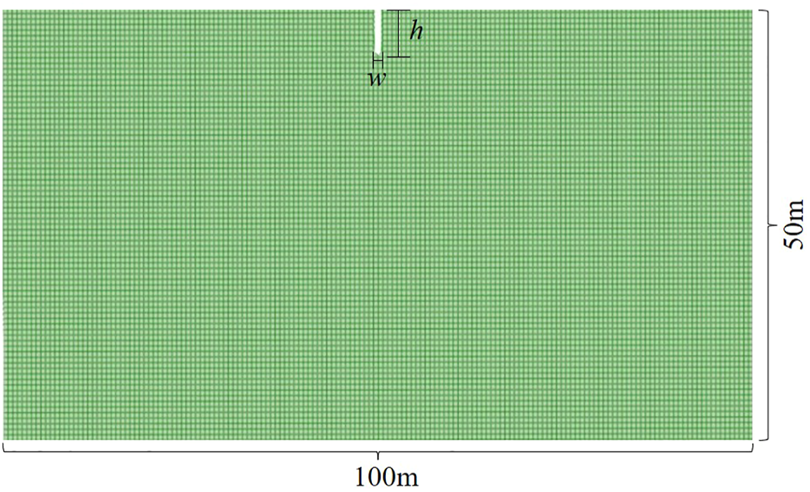
4.3.2. Evaluation of vibration isolation effect
We normalized the parameters to the trench width considering that the trench width has a small effect on the vibration isolation performance (Woods, 1968). In order to evaluate the vibration isolation effect of the open trench for plane P-wave, the maximum displacement response attenuation ratio u i /ui0 (i = x, the horizontal displacement; i = y, the vertical displacement) is introduced, u i is the displacement after setting the barrier, and ui0 is the displacement of the free-field before setting the barrier. It can be found that the smaller the value of u i /ui0, the better the vibration isolation effect.
In order to analyze the effect of incident angle on vibration isolation performance, the variation law of u
i
/ui0 with x/w for different values of h/w is shown in Figure 12. When the incident angle θ1=0°, which means the incident wave is perpendicular to the ground surface, the open trench has no vibration isolation effect for both horizontal and vertical displacements, and the displacement in the area near the trench boundary is amplified, especially the horizontal displacement is magnified infinitely. As the incidence angle is larger, we find that the vibration isolation effect of the open trench for horizontal displacement is significantly better than that for vertical displacement, and for horizontal displacement, the best vibration isolation area is near the back side of the open trench, and for vertical displacement, the vertical displacement is amplified in a certain range near the back side of the open trench, but as x/w continues to increase there are vibration isolation areas appear. For different values of h/w, with the increase of the incident angle, the vibration isolation area increases and the u
i
/ui0 value in the isolation area decreases significantly, which means that the open trench provides better vibration isolation for the incident wave with larger incident angle. Effect of incidence angle on the vibration isolation performance of the open trench.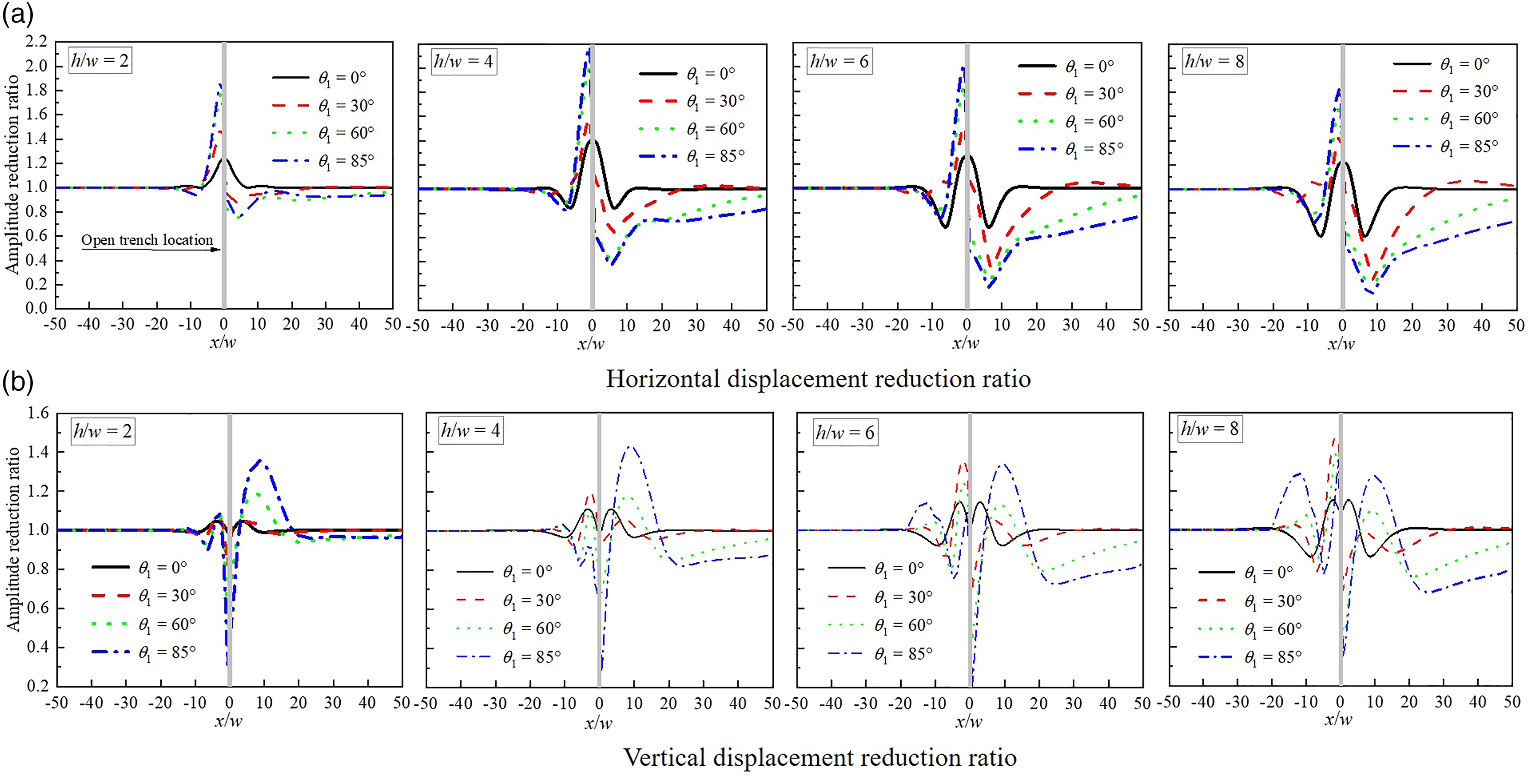
In order to further analyze the effect of the trench depth on the vibration isolation performance, the effect of the trench depth on the vibration isolation performance for different values of θ1 is shown in Figure 13. It can be seen from Figure 13 that the effect of depth on the area size of vibration isolation is small, while the effect on the u
i
/ui0 in the vibration isolation area is very obvious, and the u
i
/ui0 decreases significantly with the increase of the depth h/w. For a certain value of θ1, the appearance of the best isolation region for vertical displacement is almost independent of the depth h/w (θ1=30°, the best isolation region appears at x/w = 15; θ1=60°, the best isolation region appears at x/w = 20; and θ1=85°, the best isolation region appears at x/w = 20). In addition, the displacement amplification effect in front of the trench increases with depth h/w the more obvious it is. Therefore, we should consider both the vibration isolation area and vibration isolation efficiency in the actual vibration isolation project, choose a reasonable location to excavate the open trench according to the vibration isolation area, and choose a reasonable excavation depth according to the vibration isolation efficiency in order to achieve vibration isolation requirements under economic conditions. Effect of depth on the vibration isolation performance of the open trench.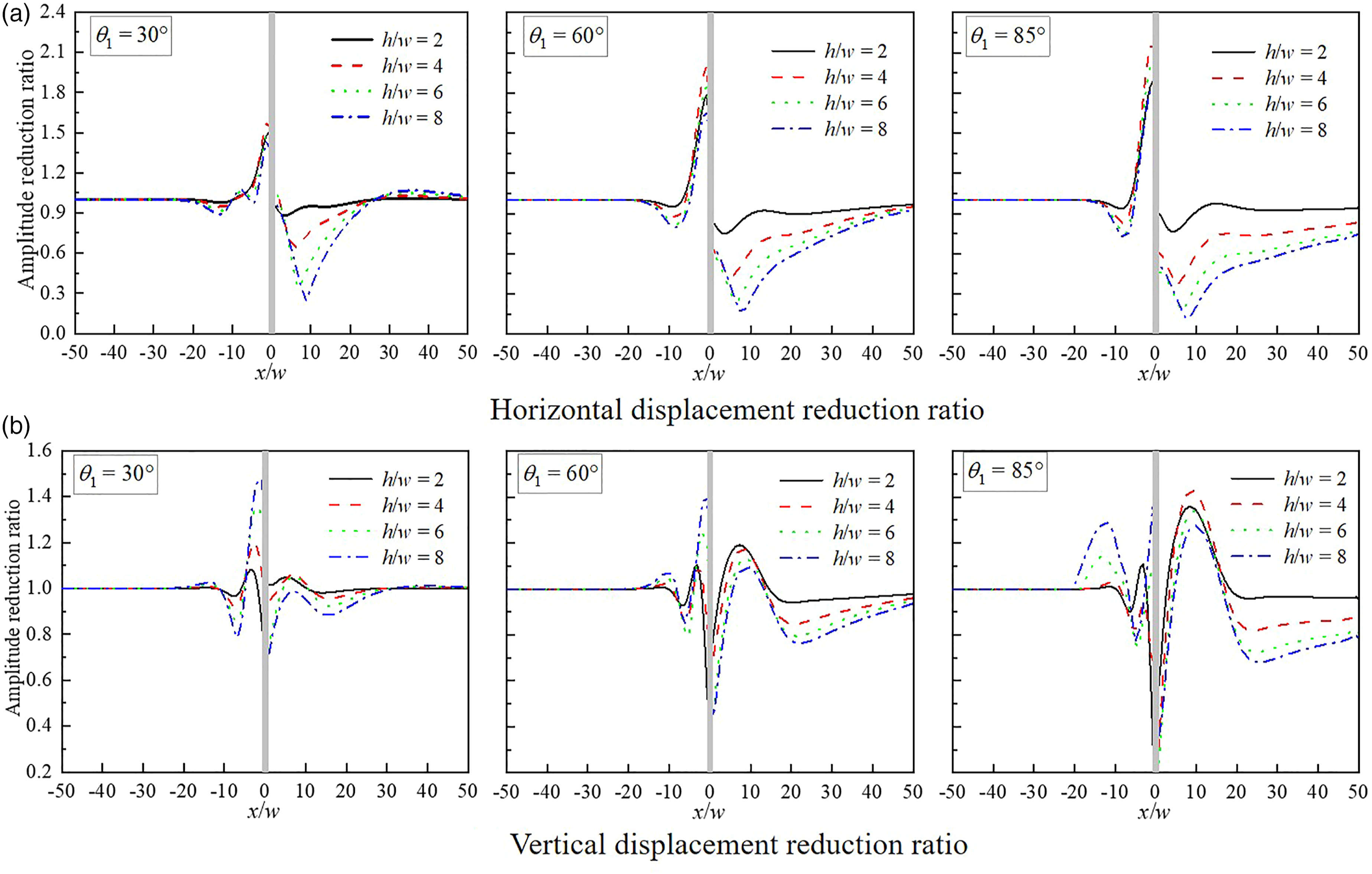
5. Conclusions
In this paper, the SBFEM is established for the time-domain analysis of the elastic wave scattering from the open trench. The quadtree domain decomposition technique is employed for SBFEM discretization of the near-field. The far-field is rigorously modeled by the displacement unit impulse response matrix. The obliquely plane elastic wave from the far-field is converted into a traction force acting on the near/far-field boundary. The effect of the open trench for the isolation of elastic waves is analyzed with the example of plane P-wave incidence. Numerical examples show that: (1) The vibration isolation effect of the open trench for horizontal displacement is better than that for vertical displacement. (2) As the incidence angle increases, the better the vibration isolation effect of the open trench; and when the incidence angle is larger, by further increasing the trench depth, which will make the trench has a better vibration isolation effect. (3) The location of the horizontal displacement vibration isolation and vertical displacement vibration isolation areas are different, so we should pay attention to the excavation location of the trench when near-field vibration isolation. With the increase of depth, the displacement amplification phenomenon near the front side of the trench is more obvious. Therefore, we should consider both the vibration isolation area and vibration isolation efficiency in the actual vibration isolation project, choose a reasonable location to excavate the open trench according to the vibration isolation area, and choose a reasonable excavation depth according to the vibration isolation efficiency in order to achieve vibration isolation requirements under economic conditions.
Footnotes
Acknowledgments
The authors are grateful to Professor Chongmin Song and Dr. Yanlin Qu from the School of Civil and Environmental Engineering, University of New South Wales, Australia, for their guidance on the work of this paper. We are also grateful to the editors and reviewers for their valuable and constructive comments on this paper.
Declaration of conflicting interests
The author(s) declared no potential conflicts of interest with respect to the research, authorship, and/or publication of this article.
Funding
The author(s) disclosed receipt of the following financial support for the research, authorship, and/or publication of this article: This work was supported by the Chinese Natural Science Foundation (Grant No. 51978320, Grant No. 11962016) and the Funds for Creative Research Groups of Gansu Province of China [20JR5RA478].