
Abstract
Axisymmetric shell structures are characterized by the presence of flexural modes which occur in degenerate pairs. However, since no practically realized structure is perfectly axisymmetric, the frequencies constituting a mode pair become unequal and causes what is commonly termed as “frequency split” between the modes. In applications such as vibratory gyroscopes, it is desired that the frequencies of the working pair of modes be equal. This work proposes an easily implementable (particularly in the industry) technique which reduces frequency split of a target mode pair. To address the frequency split trimming problem, this work investigates a model that describes the planar dynamics of a vibrating ring (which is prototypical to axisymmetric shell structures), with added mass segments. The effects of mass, as well as span, of an added segment on the ring’s natural frequencies and mode shapes are brought out. Novelties of the proposed trimming technique are that it employs added mass in the form of segments and that it has a negligible effect on the axes of the structure’s mode shapes. The technique is extended to general axisymmetric bodies, and it is validated experimentally for the case of a hemispherical resonator.
1. Introduction
Axisymmetric shell structures exhibit interesting and peculiar dynamic characteristics, arising from the symmetric distribution of mass and stiffness about an axis of symmetry. However, practical asymmetries such as material inhomogeneities or deviations that arise during machining can affect their characteristics. An interesting property possessed by thin-walled axisymmetric structures is the presence of pairs of flexural vibration modes with equal frequencies. The modes constituting a pair are spatially orthogonal and have indeterminate angular locations around the axis of symmetry (Fox (1990)). The presence of these modes is utilized in a class of modern high-performance inertial angular-motion sensors named “Coriolis vibratory gyroscopes” (CVGs).
With the advancement of meso- and micro-electro mechanical systems, there has been an increasing demand for more reliable and better performing gyroscopes. A number of designs have been conceived in which the vibrations of flexible structures such as rods, beams, or thin hemispheres are utilized to sense rotation rates (Yates (1999); Apostolyuk (2016)). These devices utilize the Coriolis coupling between a pair of orthogonal modes to sense rotations and hence are named CVGs. Conventionally, these modes are named as the drive and the sense modes of operation. The structure is oscillated at resonance along the drive direction, at its natural frequency, by employing certain control loops. When the structure is rotated about an axis perpendicular to the plane of oscillations, the sense direction (which is perpendicular to the drive direction and which falls in the plane of oscillation) experiences an acceleration which is proportional to the applied rotation. The acceleration is sensed and is reported as the output of the CVG. The sensing efficiency is maximum when the frequency split is minimum. It is in this context that frequency trimming needs to be performed on practically realized resonators.
As opposed to conventional gyroscopes which employ gimbal suspended wheels, CVGs are perfect for applications such as long-life deep-space missions since they employ no rotating parts and since they are immune to friction or wear related performance deterioration. But, as with all instruments, the CVG is not without practical problems. In particular, they require an ideal vibrating member; one in which the amplitude of oscillation is not reduced by energy losses and in which there is complete dynamic symmetry so that the plane of oscillation precesses at a rate determined only by the angular rotation of the instrument (Friedland and Hutton (1978)).
A practically realized resonator would rarely be perfectly axisymmetric. Material, machining, or geometry related imperfections can cause deterioration of the vibratory properties and can lead to a phenomenon termed as “frequency splitting” (Fox (1990); Zhang et al. (2021)), in which the frequencies of a mode pair become unequal. Moreover, the mode shapes acquire certain spatial directions and causes a loss of dynamic symmetry. Several methods have been established to detect material inhomogeneities such as those investigated by Mousavi et al. (2022), Chen and Li (2022), and Chen et al. (2022).
Most of the past research addressing axisymmetric structures with carried masses (or imperfections) either considered perturbations idealized to be of the “point mass” form as in Fox (1990); Gil Park et al. (2008); Behbahani and M’Closkey (2017); Rourke et al. (2001) or to be of the “sinusoidal” form as in Bisegna and Caruso (2007); Joubert et al. (2014); Ma and Su (2015); Chaudhuri (2018); Rodrigues et al. (2020). Unlike these articles, carried masses of the segmented form (such as that investigated in Park et al. (2008)) which are more realistic than the previously mentioned forms are investigated here. Addition of mass on an imperfect axisymmetric structure can also correct frequency split (Fox (1990)). Practically, the addition of masses of the truly point or sinusoidal forms is difficult while addition of mass segments is much easier as is demonstrated later in the section on experimental validation. Frequency split can also be critical in the design of other axisymmetric structures like bells (Perrin et al. (1995)) and automobile tires (Allaei et al. (1986)).
In this work, one of the most common non-idealities observed in thin axisymmetric structures termed frequency splitting is modeled, and a practically implementable trimming technique which aims to correct it is investigated. Our interest lies in the trimming of the n = 2 mode of vibration; however, the technique can be extended to any pair of modes. This article distinguishes itself from previous research works as it investigates the effect of realistic segmented carried masses as opposed to conventional point or sinusoidal imperfections. It also brings out the effects segment mass and span can have on the natural frequencies and the mode shapes of a circular ring. Once these are established, a split trimming technique is developed which addresses the frequency split problem of axisymmetric resonators, without altering their nodal orientations. This is greatly beneficial in the practical point of view, especially in the assembling of CVG sensing units. This article is organized as follows. After the introduction, the phenomenon of frequency splitting is explored by employing a model of a vibrating ring which is prototypical to all axisymmetric resonating structures. Next, the technique employed to solve the governing equations is described, and the results obtained are compared with existing literature to benchmark the solution method. Thereafter, using the model, the effects of certain key parameters associated with added mass segments are explored. The model is used to explore a trimming scheme, in which split reduction is achieved without causing a significant deviation in the mode shapes. Next, the technique is extended to non-ring geometries and is validated experimentally. Finally, the results are summarized and the conclusions are presented.
2. The model
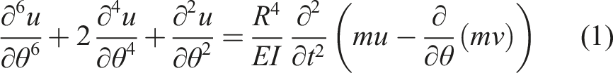
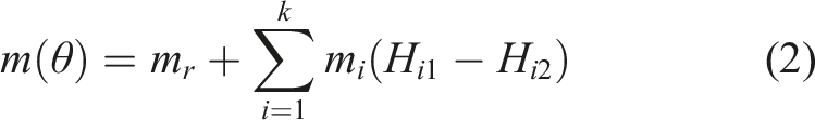
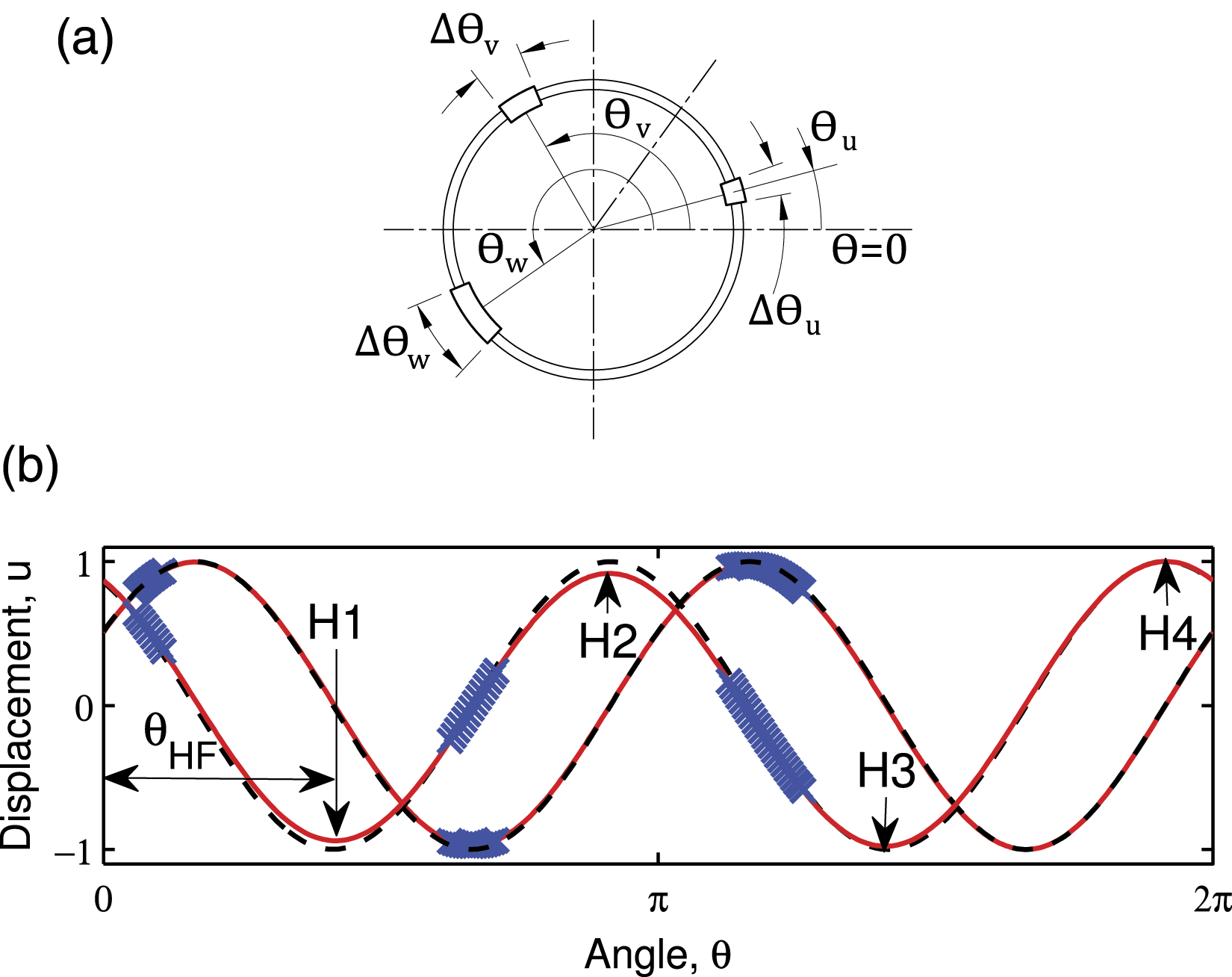
The frequency split trimming problem of axisymmetric shell-type structures is investigated here by examining their dynamic behavior using a model of a vibrating ring which is prototypical to all axisymmetric structures. The equations governing the vibrations of a thin ring
1
of radius R undergoing in-plane motion are derived in Hong and Lee (1994); Park et al. (2008) as Schematic of the model of a thin vibrating ring.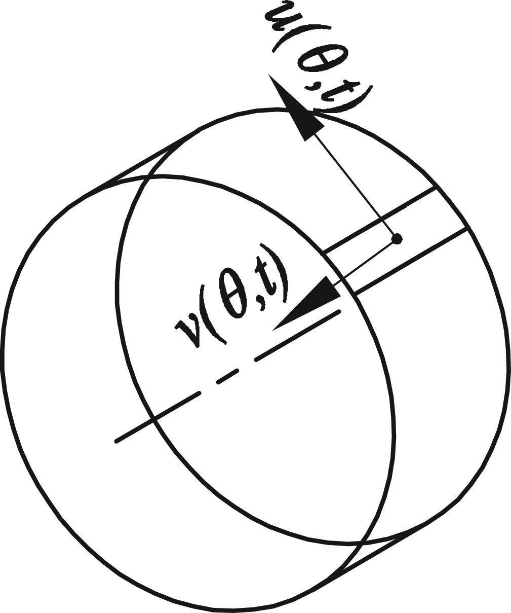
3. Method of solution
Galerkin’s method is employed to obtain the natural frequencies and mode shapes. The mode shapes of a perfect ring (where m
i
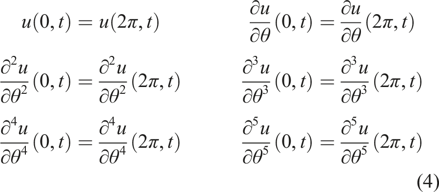
= 0) are used as “test functions” to expand the solution (Thomsen (2003)). Note that these functions satisfy the boundary conditions given in equation (4). The solution is expanded as
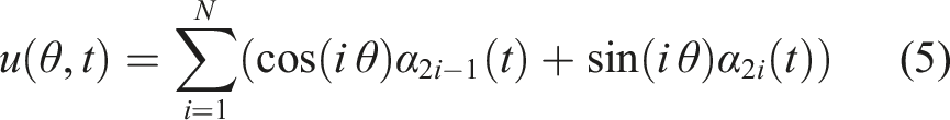
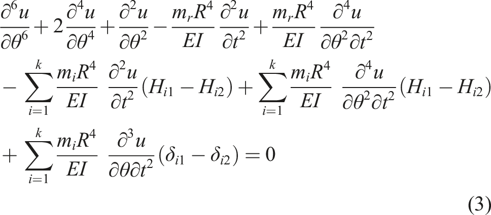
This series expansion much like the ones employed in Behbahani and M’Closkey (2016); Matsunaga (1997) is substituted in equation (3).
The resulting expression is multiplied with each of the test functions and integrated with respect to θ from 0 to 2π to discretize the governing partial differential equations into a system of ordinary differential equations of the following form

Here,
The method of solution employed in this work is first bench-marked against existing literature. For this purpose, the frequencies of a perfect ring with m
i
= 0 obtained from equation (6) are compared with those obtained from the closed-form expression Mode shapes of (a) the n = 2 mode and (b) the n = 3 mode of a perfect ring.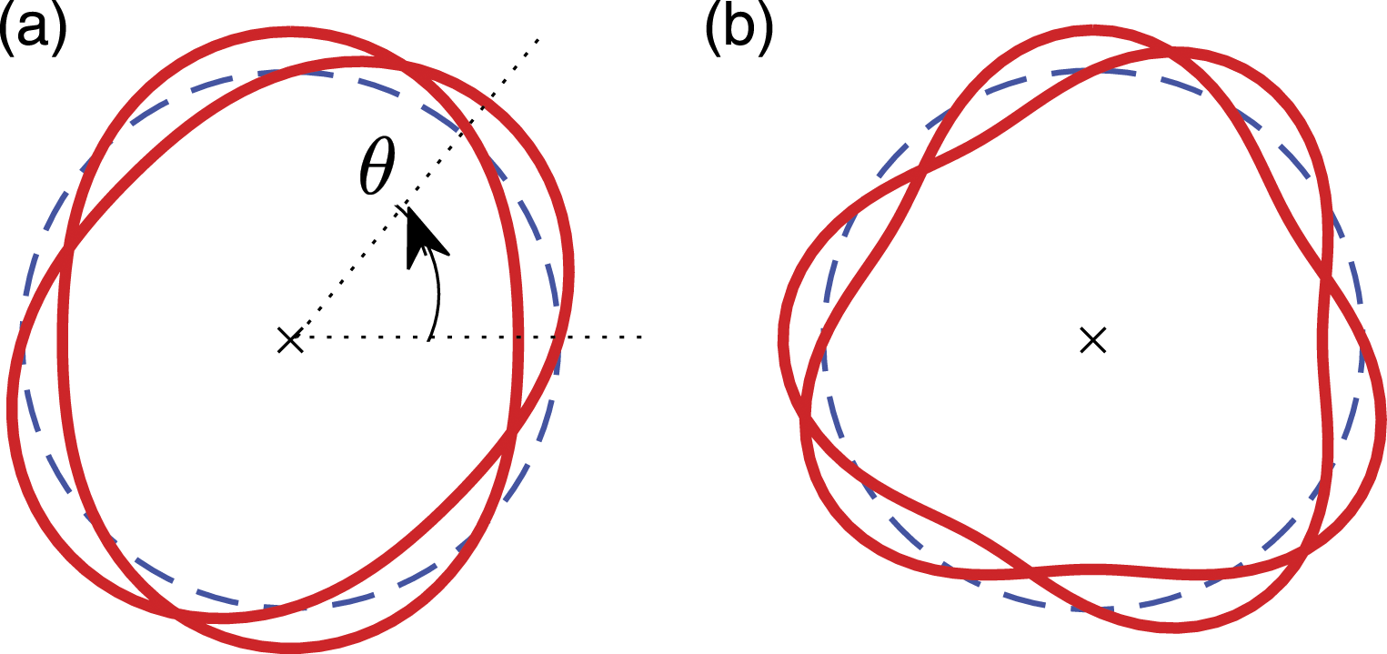
4. Results
The solutions predicted by the model are presented next.
4.1. Effect of an added mass segment on the frequencies of a perfect ring
Frequency splits of a perfect ring carrying a mass segment in Hz with m1 = 0.3m r and Δθ1 = π/20.
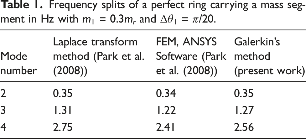
An increase in the mass per unit length (m1) of an added mass segment causes the split of a perfect “resonator” to increase. The axes assume directions such that the low frequency anti-nodal axis aligns to the centroid of the added mass segment. The effect m1 has on the frequencies of the ring is presented in Figure 3. Note that the split introduced in the n = 3 pair is greater than that introduced in the n = 2 pair. This trend, which is also reflected in Table 1, continues for all higher mode pairs. Variation in the natural frequencies corresponding to (a) the n = 2 mode and (b) the n = 3 mode of a ring carrying a mass segment, as the ratio m1/m
r
is varied. θ1m = π/4 and Δθ1 = π/20.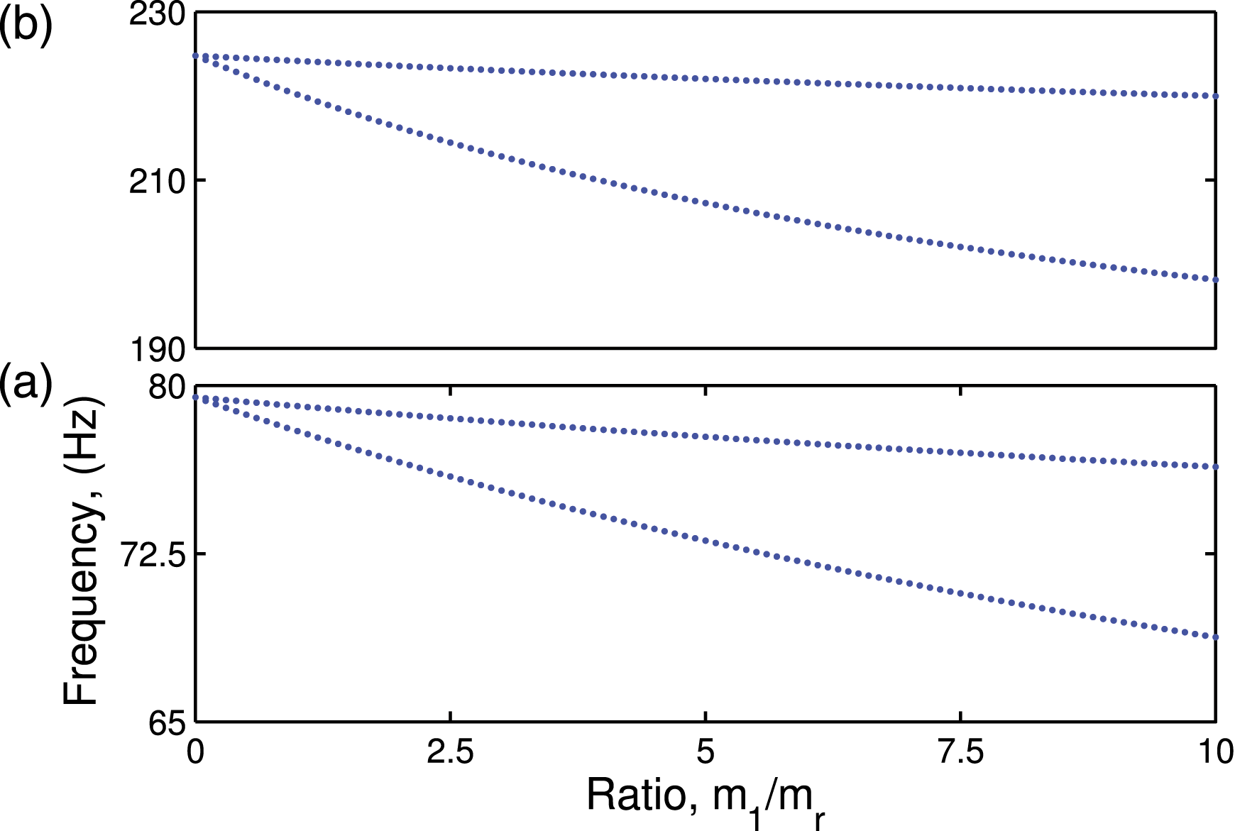
The mode shapes of the ring corresponding to the case when m1 = 2m
r
for the n = 2 mode are presented in Figure 4(a).
3
The mode shapes of a perfect ring are also presented for comparison. In these depictions, the angular coordinate θ of Figure 2 is presented as a linear coordinate along the horizontal axis. This way of presenting the mode shapes is useful to compare the subtle differences which would be difficult to notice in the conventional representation of Figure 2. The mode shapes corresponding to the lower frequencies are marked LF and those corresponding to the higher frequencies are marked HF. The extremum points of the crests and the troughs indicate the orientation of the corresponding anti-nodal axes. It is interesting to note that although both frequencies of a mode pair decrease, reduction in the frequency of one is much more than that of the other. Moreover, the mode shapes also deviate from those of the perfect structure. The deviation in the mode shapes is greater for a larger value of m1. This result holds true even for the n = 3 mode pair, as is observed in Figure 4. Note that the m
i
values selected for obtaining the results of Figure 4 are such that the deviation in the mode shapes is appreciable. In reality, such high values are uncommon. Normalized mode shapes corresponding to (a) the n = 2 mode and (b) the n = 3 mode, of a ring carrying a mass segment (marked in the red solid line-type) in comparison with those of a perfect ring (black dashed line-type), when m1 = 2m
r
. θ1m = π/4 and Δθ1 = π/20. (c) and (d) are the corresponding mode shapes when m1 = 10m
r
. The (blue) cross-hatched regimes mark the locations of added mass segments.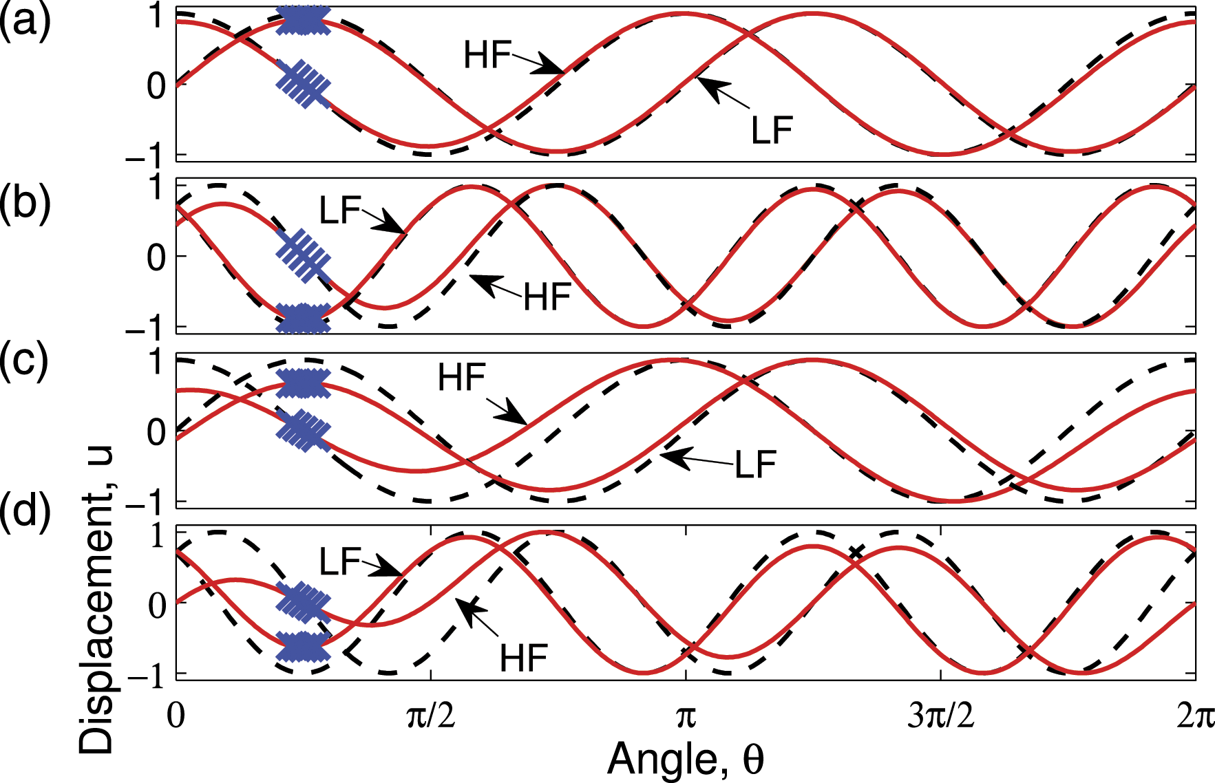
Another important factor determining split is the parameter Δθ1, which models the angular span of the mass segment. As the span increases, the total mass of the added segment increases, and therefore, all natural frequencies reduce in magnitude. This is evident in Figure 5 which presents the loci of natural frequencies of the n = 2 and n = 3 modes as Δθ1 is increased. Variation in the natural frequencies corresponding to (a) the n = 2 mode and (b) the n = 3 mode of a ring with an attached mass segment as the ratio Δθ1 is varied. θ1m = π and m1 = 0.1 m
r
.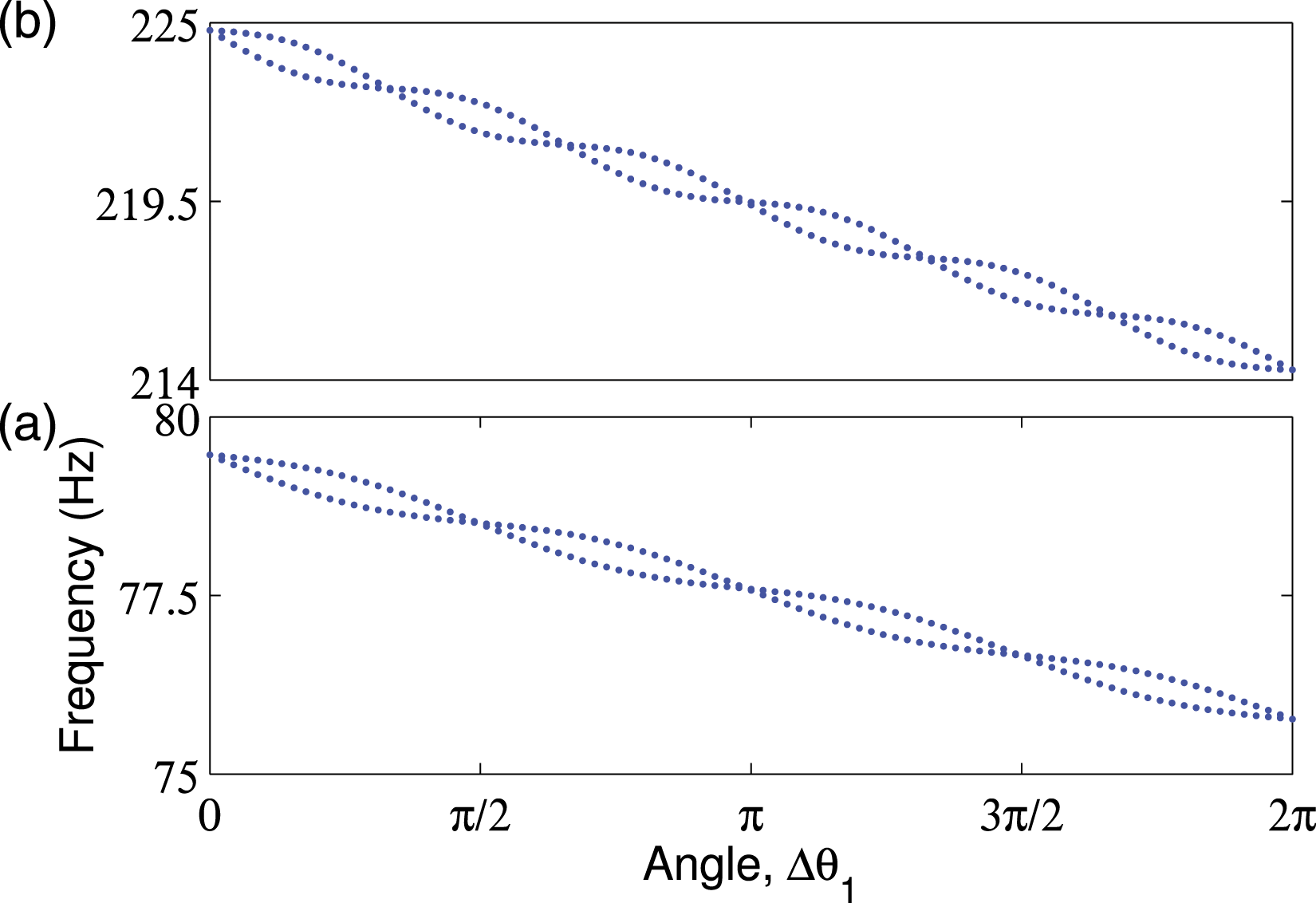
It is expected that for a particular mode pair, an increase in the mass of the segment can increase the split. However, this is true only when the mass is increased keeping the span constant. An increase in mass accompanied by an increase in span need not increase split. From Figure 5, it is evident that the frequency split of the n = 2 mode becomes zero for four distinct values of Δθ1, while that of the n = 3 mode at six distinct points, as Δθ1 is varied from 0 to 2π. There are 2n (where n is the mode number) values of Δθ1 for which an added mass segment introduces no split for that particular mode. An interesting result is that an added mass segment spanning Δθ1 = π radians neither induced a split on the n = 2 mode, nor on the n = 3 mode.
These results suggest that by selecting the parameters m1 and Δθ1, an added mass segment can modify the frequencies, the mode shapes, and the orientations of the nodal axes of a ring resonator. Such an added mass segment when located appropriately can also be utilized to reduce the frequency split of an imperfect ring as described in the following section.
4.2. Effect of added mass segments on the frequencies of an imperfect ring
The practical non-idealities associated with the realization of axisymmetric resonating structures lead to the deterioration of its vibratory properties, such as Q-factor and frequency split (Sharma et al. (2020); Anilkumar et al. (2020); Zhou and Li (2021)). Several researchers, for instance Fox (1990); Rourke et al. (2001); Joachim and Lin (2002); Gallacher et al. (2003); Schwartz et al. (2009, 2015); Xiao et al. (2017), have developed techniques to balance the frequencies of a realized resonator. These techniques eliminate frequency split by “trimming,” a process which involves the addition or removal of material from predetermined locations of the resonator. An effective technique for mechanical trimming of rings is that which assumes an imperfect resonator to be equivalent to a perfect resonator with an added point mass (Fox (1990)). With the addition of this point mass, the frequencies constituting the mode pairs (which were equal for the perfect ring) become unequal. To adjust the frequencies, a trimming mass was attached to such a location on the ring that it reduced the frequency of the higher mode. This section investigates two alternate implementation schemes of this technique.
As depicted in Figure 7, there are four equivalent locations on the ring where a trimming mass can be added (to balance the n = 2 mode pair). Two alternative trimming schemes, namely, a “single-location trimming” and a “multi-location trimming” are compared next. In the single-location scheme, the trimming mass is added in such a way that the centroid of the added mass element coincides with any one of the four anti-nodes, while in the multi-location scheme, this mass is distributed equally among all four such locations.
4.3. Single-location trimming
Next, a hypothetical unbalanced ring resonator is modeled by introducing imperfections in the form of three mass segments denoted by the subscripts u, v, and w. A schematic of these segments with their angular locations are presented in Figure 6(a). Although in reality, the true nature of an imperfection associated with a realized resonator is difficult to find, we employ such a model since the effect of any complicated imperfection can be assumed to be equivalent to that which produces a split in the frequencies of the various mode pairs. Equation (2) becomes (a) Schematic of the hypothetical imperfect ring. Parameters θ
u
= 0.26 rads, Δθ
u
= 0.16 rads, m
u
= 0.3m
r
, θ
v
= 2.09 rads, Δθ
v
= 0.26 rads, m
v
= 0.6m
r
, θ
w
= 3.75 rads, Δθ
w
= 0.42 rads, and m
w
= 0.25m
r
. (b) Normalized mode shapes of the n = 2 mode of the imperfect ring. The blue cross-hatched regimes represent added mass segments. The black dashed line-type presents the mode shapes of the corresponding perfect ring (with m
u
= m
v
= m
w
= 0). Schematic of (a) the imperfect ring resonator detailed in Figure 6(a), depicting the locations of the HFA and the LFA obtained on solving equation (6). The locations on the ring (depicted as hatched segments) where trimming masses can be added as per (b) the single-location scheme and (c) the multi-location scheme.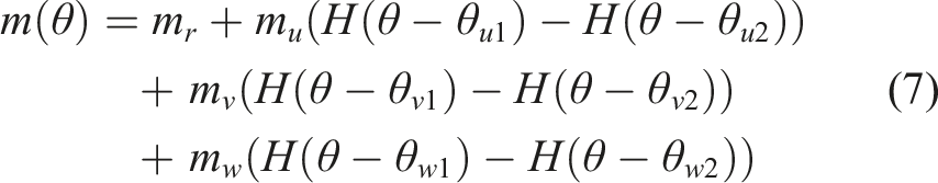
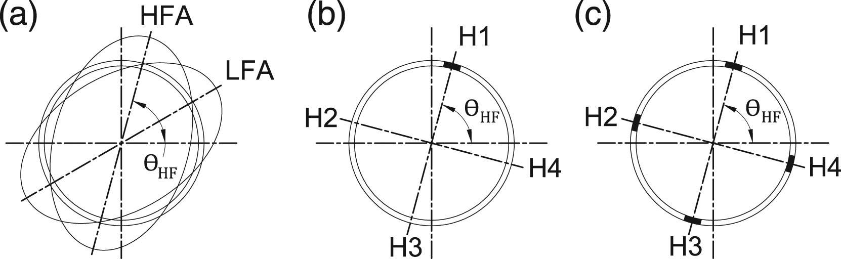
The addition of a mass segment on the HFA of the unbalanced ring of Figure 4(a) decreases the frequency of the higher frequency mode (by a magnitude greater than the decrease in the frequency of the low frequency mode) and thereby causes split trimming to be possible. For small magnitudes of added masses, the decrease in split is directly proportional to the masses. The proportionality constant (determination of which is detailed in the section of experimental validation) between the mass of a segment and the reduction in split dictates the magnitude of mass to be added.
Trimming mass can be added at any one of the four HFA locations. Next, these four possibilities are explored. The mode shapes of the imperfect ring with a trimming mass added at location H1, as depicted in Figure 7(b), are presented in Figure 8(a). Normalized mode shapes of the n = 2 mode of a balanced ring obtained with the addition of single-location trimming masses at H1, H2, H3, and H4 are presented, respectively, in (a), (b), (c), and (d). The (red) solid line-type depicts the mode shapes of the balanced rings. The (black) dashed line-type depicts the mode shapes of the corresponding perfect ring. The (blue) cross-hatched regimes represent locations where trimming masses are added. (e) The mode shapes of the n = 2 mode obtained after addition of the trimming masses at H1, H2, H3, and H4 together.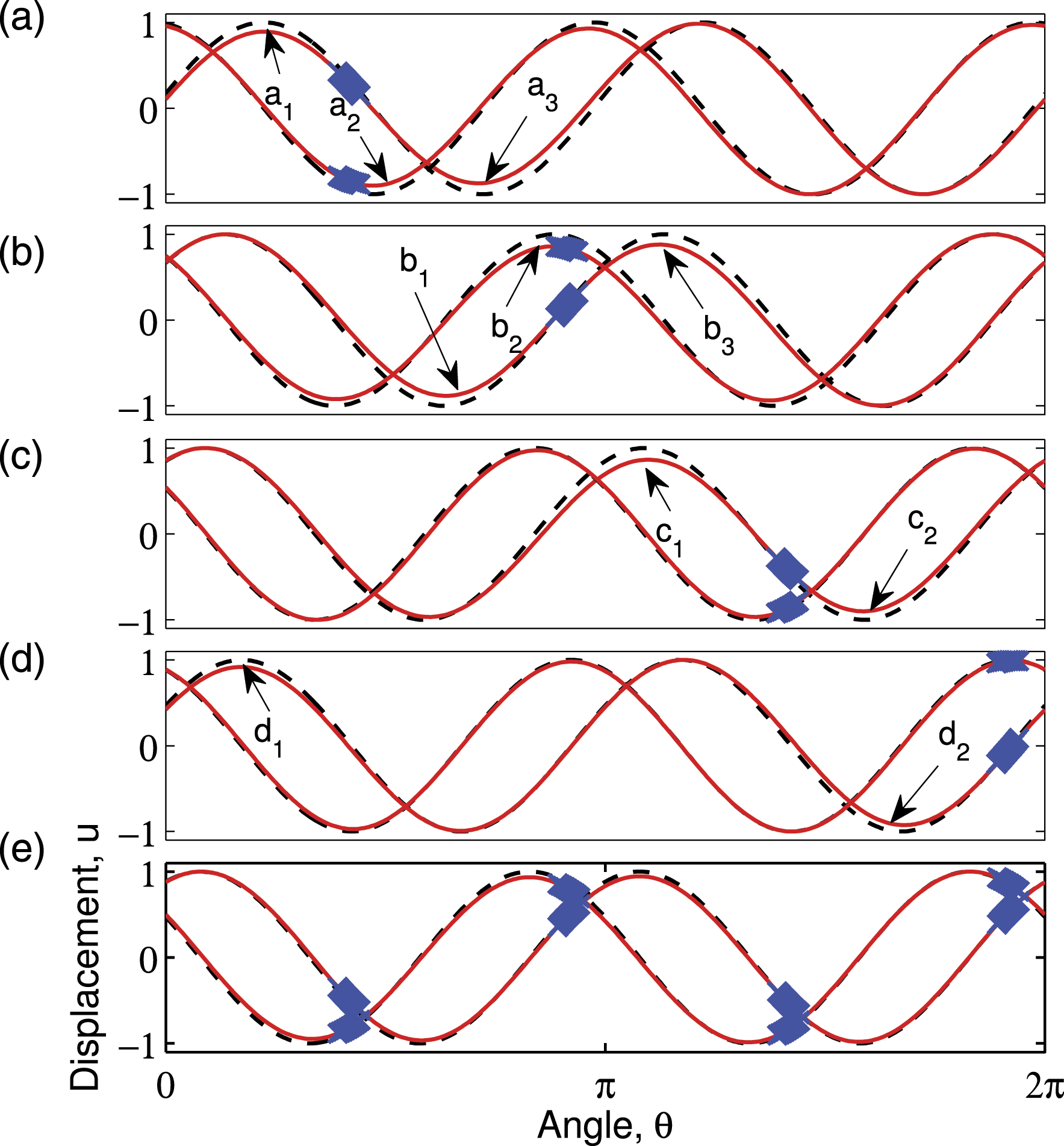
Equation (2) for this case becomes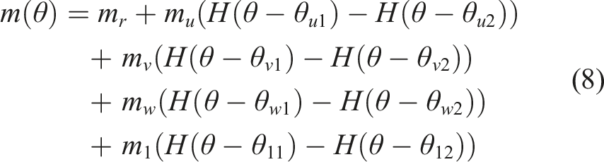
Figure 8(b), (c), and (d) present the mode shapes of the imperfect ring with a carried trimming mass segment at the locations marked H2, H3, and H4, respectively. The deviations in the mode shapes from those of the analogous perfect rings are marked by arrows labeled b1, b2, b3, c1, c2, d1, and d2. It is clear from Figure 8(a)–(d) that, among the four possible single-location trimming schemes, it is the trimming mass at H4 which produces the least deviation in the mode shapes. However, in an industrial setting, it is difficult to identify the subtle differences and to choose one out of the four possible trimming schemes.
4.4. Multi-location trimming
Another possibility is to add trimming masses equally on all the four HF anti-nodes as depicted in Figure 7(c). In this case, equation (2) becomes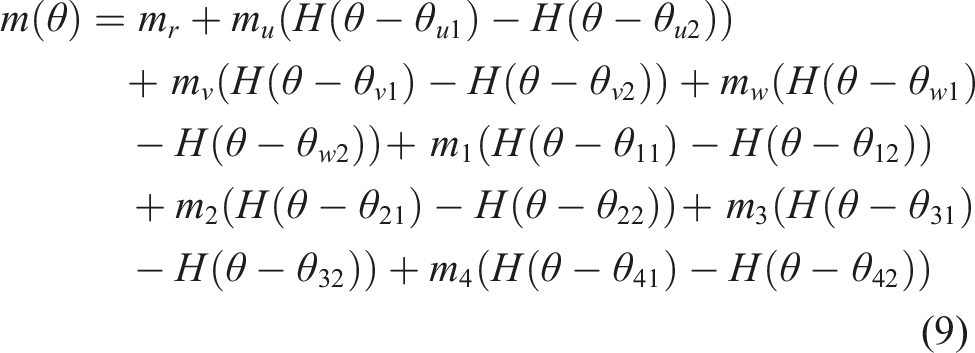
A comparison between the mode shapes of the balanced ring obtained as a result of the four-location trimming scheme is presented in Figure 8(e). It is observed that this scheme causes a smaller deviation in the mode shapes as compared to the single-location scheme of Figure 8(a)–(d).
5. Extension to non-ring geometries and experimental validation
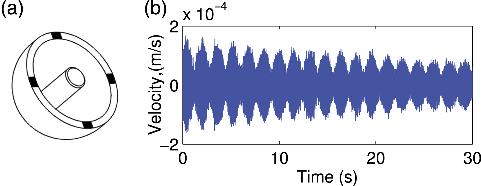
Models of vibrating rings are prototypical to the investigation of the dynamic behavior of general engineering “bodies of revolution” such as bells, cylinders, tires, gears, and discs (Fox (1990)). In this section, the multi-location trimming scheme described earlier is experimentally validated, and extended to the case of a non-ring geometry, particularly to that of a high-performance quartz-based hemispherical resonator (HR). A photograph of the HR investigated here is presented in Figure 9(a). Note that the HR is metallized with a thin layer of gold so as to make it electrically conductive, as is required for the functioning of a (capacitive) CVG. The procedure described next for the HR can generally be applied to any axisymmetric resonator. (a) Photograph of the HR (of 15 mm mean radius and 1 mm thickness) under investigation and (b) mode shapes corresponding to the n = 2 mode of the HR obtained from ANSYS simulations.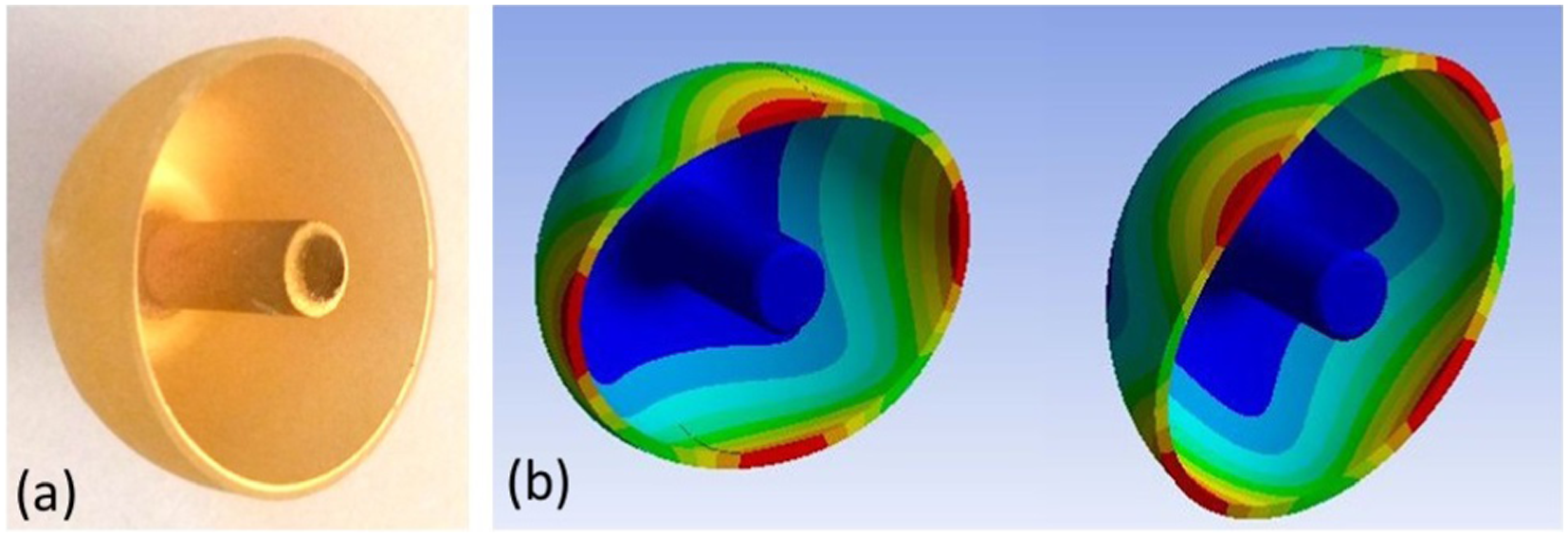
The change in split with the addition of a mass segment depends on the exact geometry of the resonator as well as the mode of interest. Here, our aim is to trim the n = 2 mode of flexural vibration of the HR. The natural frequencies of this particular mode pair for a perfect HR have been estimated from ANSYS simulations, and the corresponding mode shapes have been presented in Figure 9(b). A strong resemblance of these shapes to those presented in Figure 2(a)is noticed.
Extension of the trimming procedure to general axisymmetric bodies involves the evaluation of the “added mass to split” ratio. This proportionality constant or “scale-factor” can be estimated through experiments as well as through finite element simulations. For the HR of Figure 9(a), a known mass was first attached to the rim (which is the location where trimming masses are planned to be added), and the split change introduced by this mass was measured experimentally. Details of the experimental setup are presented in the following paragraphs. Assuming a linear relationship between the mass added and the change in split (which holds true for small masses, refer Behbahani and M’Closkey (2016)), a scale-factor of 0.26 mg/Hz was obtained. This value was further verified from finite element simulations as well. The effect of added mass segments at the locations depicted in Figure 12(a) on the frequencies of the n = 2 mode of the HR are presented in Figure 10. The masses m
i
, i = 1, 2, 3, 4 denote the four equal masses which are added at the locations marked on Figure 12(a). The trend in the frequencies resembles that which was earlier captured in Figure 3. Loci of the natural frequencies corresponding to the n = 2 mode of the HR as the masses of added segments are varied, obtained from ANSYS simulations.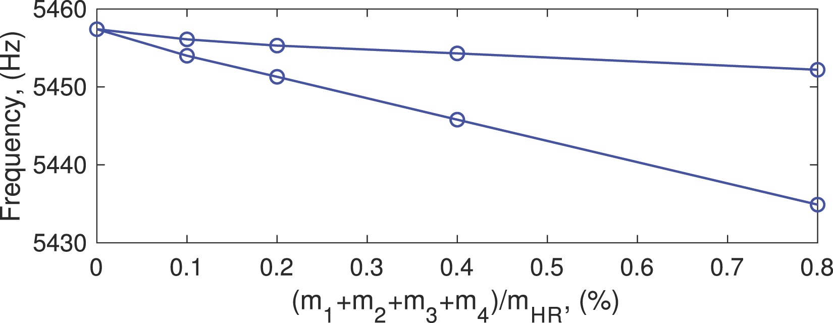
A schematic depiction of the experimental setup used to capture the frequencies of the n = 2 mode of the HR using a laser Doppler vibrometer (LDV) is presented in Figure 11. The HR was located on a rotary stage which was further situated within an evacuated chamber with a transparent window. The resonator was excited sinusoidally at a natural frequency till the amplitude of vibrations attained a constant value. The decaying response obtained once the excitation was switched off is termed “ring down.” Figure 12(b) depicts a typical ring down response. The beating between two adjacent frequencies which is an indication of frequency split is noted. These free-responses are a linear combination of the resonator’s natural frequencies. The ring down response of a general (non-nodal) point for the n = 2 mode was captured, and its frequency components were obtained by employing a fast Fourier transform (FFT). Schematic of the experimental setup. The dot-dash line-type indicates the axis of the rotary stage. (a) Schematic depiction of the trimming locations on an HR and (b) an experimentally obtained ring down response of a general (non-nodal) point on an unbalanced HR.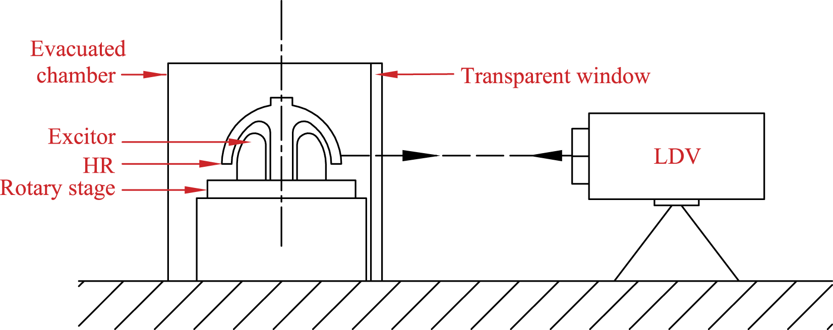
Researchers have reported several methods to add/remove mass in order to trim the frequencies of resonators experimentally. For instance, chemical etching was employed in Basarab et al. (2015), addition of magnets in Schwartz et al. (2009), poly-silicon deposition in Joachim and Lin (2002), and laser ablation in Gallacher et al. (2003). However, in this work, we employ metal coatings much like the method described in Courcimault and Allen (2005). Trimming was performed in three sequential steps, each progressively reducing the split. Predetermined amounts of mass were deposited on all four HFA locations of the resonator through controlled metal coating around the high-frequency anti-nodes following the scheme which was presented in Figure 7(c).
The first step in trimming was to locate the HFA. This was performed by observing the frequency components of ring down measurements from various angular locations on the HR. Figure 13 depicts the frequency components of various such measurements made across angular locations separated by 5° each and spanning one quadrant of the HR. The frequency components from points on the remaining three quadrants exhibited a similar trend. For a general angular location, the velocity amplitudes peaked at both frequencies. The HF and LF axes were identified from the fact that for a nodal axis, the amplitude corresponding to one of these frequencies becomes zero. For instance, at the HF axis, the component corresponding to the LF becomes zero. Frequency components of experimentally obtained ring down responses from various locations along the circumference of the HR.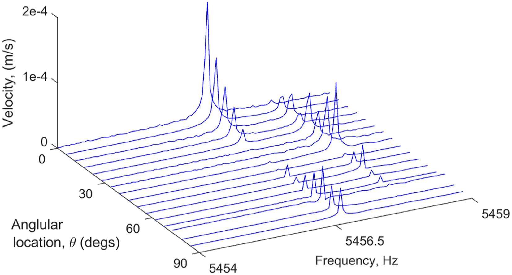
Once the axes were identified, the trimming masses were added. For the purpose of illustrating the technique described here, the entire trimming mass was not added at once. Mass addition was undertaken in three steps so that the variation of split with added mass could be monitored. The frequency components of velocity measurements performed at a non-nodal point on the HR obtained at the three stages of trimming are depicted in Figure 14. The frequency split of the unbalanced resonator was reduced from 2.74 Hz (Figure 14(a)) to less than 0.03 Hz (Figure 14(d)), which is the maximum frequency resolution of the data acquisition device employed for these measurements. It was noted that the trimming procedure presented here had a negligible effect on the Q-factor of the mode of interest. In the case of the HR, the technique employed here reduced split to frequencies better than 10−5 times that of the frequency of the working pair of modes. (a) Frequency components of the experimentally obtained responses for the n = 2 mode of the unbalanced HR of Figure 9(a). (b)–(d) depict in sequence the components at various stages of trimming.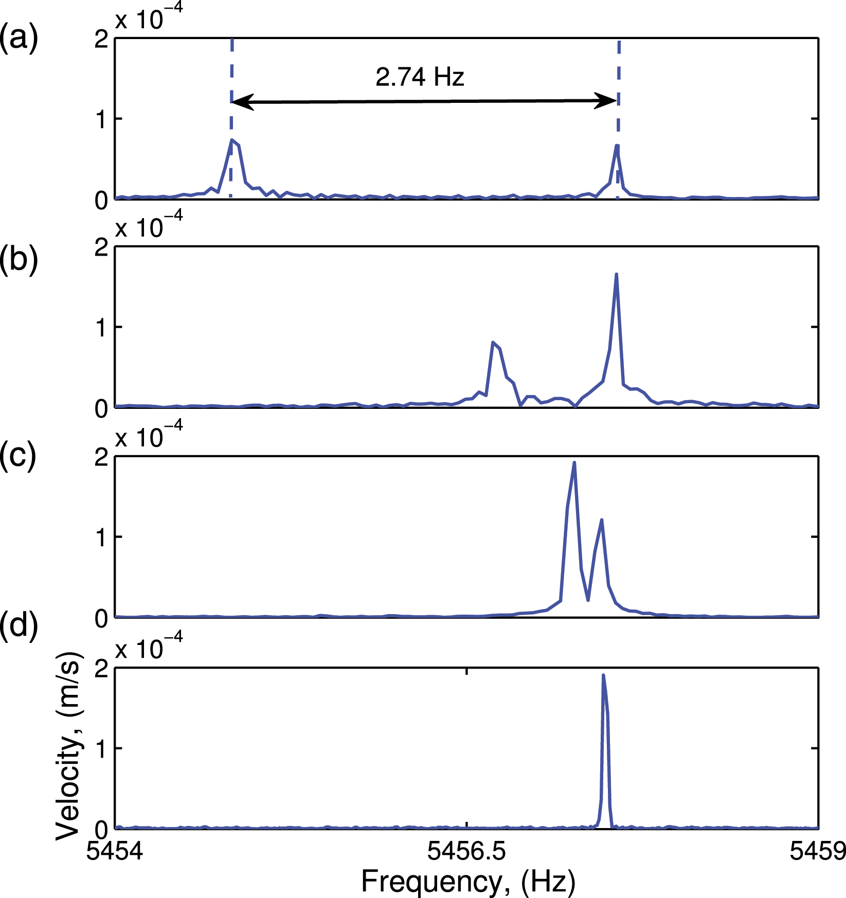
6. Discussion
An added mass segment decreases the frequencies of the planar bending modes of a circular ring as evident in Figure 3. This effect is analogous to the decrease in the natural frequency
The single-location trimming technique can introduce a net mass imbalance (a change in the location of the center of mass) to the ring which can lead to a deterioration in Q-factor and also can make the ring sensitive to external vibrational disturbances (Fox (1996); Wang et al. (2017)). In the context of applications such as CVGs, the sensitivity to (environmental) vibration affects the measured angular rates and therefore can deteriorate a gyroscope’s performance. The multi-location trimming technique preserves both the mode shapes and the location of the center of gravity and is superior to the single-location scheme.
7. Conclusions
Axisymmetric shell structures are employed in engineering applications such as high-performance CVGs due to the peculiar property that they exhibit pairs of orthogonal modes with equal frequencies. However, due to machining and material inhomogeneities, the frequencies corresponding to mode pairs of realized structures would rarely be equal. Therefore, a “trimming” of resonators needs to be performed which involves either the addition or the removal of predetermined amounts of material from precise locations on the resonator. A mathematical model of a circular vibrating ring which is prototypical to all axisymmetric resonating structures is employed to explore the effect of an added mass segment. It is found that: • An added mass segment can alter both the natural frequencies and the mode shapes of a circular ring resonator. • Frequency trimming can be achieved by adding mass segments at specific locations of a resonator. • Single-location trimming causes a deviation in the mode shapes of the original resonator. • Distributing the trimming masses on multiple equally spaced angular locations reduces the deviation and also preserves the axes of the mode shapes. The number of such locations depends on the mode shape of the mode being trimmed. • The technique developed can be extended to adjust the frequencies of non-ring axisymmetric structures as well. • In quartz hemispherical resonators, the technique can be employed to reduce the frequency splits to orders of magnitudes better than five times that of the frequency of the working pair of modes.
Footnotes
Acknowledgments
The authors thank Shri. Ullas Jose (Library, IISU) for his valuable support for the literature review.
Declaration of conflicting interests
The author(s) declared no potential conflicts of interest with respect to the research, authorship, and/or publication of this article.
Funding
The author(s) received no financial support for the research, authorship, and/or publication of this article.