
Abstract
To exploit the potential application of supporting nonlinearity in marine engineering, an attempt is made to establish the transverse forced vibration analysis model of a double-beam system supported by a spring-mass system that is nonlinear. This kind of vibration system consists of two beam sections, boundary supports, a coupling component, and a nonlinear spring-mass arrangement. The variational approach and the generalized Hamiltonian concept are used to develop the governing equations of such a double-beam system. The Galerkin truncation method (GTM) is a technique for obtaining the governing equations’ residual equations. By solving the associated residual equations numerically, the nonlinear responses of the double-beam system can be figured out. The GTM has good solidity and correctness in the prediction of the vibration system’s forced transverse vibration. The dynamic responses of the double-beam structure supported by a spring-mass system that is nonlinear are subtle to their initial calculation values. Appropriate parameters of the nonlinear support will subdue the level of vibration at the boundary of the double-beam system. In contrast, unsuitable parameters of the nonlinear support motivate complex dynamic responses of the double-beam system and harmfully influence the vibration repression at the boundary of the vibration system.
Keywords
1. Introduction
In marine engineering, shafting systems are widely encountered in the ship’s power transmission system. Shafting systems typically consist of several segments, supporting bearings, coupling elements, and others. Shafting systems on ships are vulnerable to unexpected structural vibration due to the external excitation loading generated by energy and power equipment. Excessive structural vibration negatively influences the stability of shafting systems. A good understanding of the shafting system’s vibration characteristics and dynamic behaviors plays a crucial role in its low-vibration design and its attenuation.
For the vibration characteristics of shafting systems, Haddara (1988); Wevers (1975); and Warikoo and Haddara (1992) investigated the transverse vibration behaviors of the propeller shafting system. Wu and Yang (1995) investigated the torsion-and-flexure–coupled vibration characteristics of a shafting system. Murawski (2004) studied the axial vibrations of the shafting system under complex boundary conditions. Jiang et al. (2004) used the energy technique to predict the torsional-axial vibration characteristics of the shafting system. Shi et al. (2010) studied the shafting alignment under hull deformations. Safina (2010) and Zhu et al. (2012) investigated the transverse vibration of different shafting systems. Murawski and Charchalis (2014) proposed 2 simplified methods to analyze the torsional vibration characteristics of shafting systems. Zou et al. (2015) studied the super-harmonic resonances of the shafting system, in which the longitudinal-transverse vibration was fully considered. Huang et al. (2015, 2016) deeply analyzed the vibration characteristics of a marine propulsion shaft through the coupled finite element method and experiment measurement. To foretell the transverse vibration characteristics of ship propulsion, Xu et al. (2020) combined the boundary-smoothed Fourier series approach with the energy concept. Tian et al. (2022) predicted the vibration characteristics of the podded propulsor shaft through an analytical approach. Rao and Reddy (2022a) proposed a method for the detection of open cracks or grooves on a rotating stepped shaft based on the wavelet transforms. By employing the corresponding method, the characteristics of cracks can be accurately detected. Then, Rao and Reddy (2022b) proposed a data-based crack detection technique in rotors based on Discrete Wavelet Transforms (DWT) and Adaptive Neuro-Fuzzy Inference Systems (ANFIS), which is valuable and had great potential for engineering application. From the above studies, in the evaluation of the transverse vibration of shafting systems, the shafting system could be modeled as beam structures with some coupling elements and supports.
With the prosperous advancement of vibration theory, engineers attempted to introduce nonlinearity in engineering to subdue the harmful vibration of formation. Within this background, scholars designed various nonlinear equipment and deeply studied its vibration behaviors (Cheng et al., 2016; Fulcher et al., 2014; Leblouba et al., 2019; Niu and Chen, 2021; Yan et al., 2018). To understand the potential application of nonlinear equipment in engineering practice, a large number of scholars analyzed the transverse vibration of beam frameworks with various nonlinearities, in which the beam structures are one of the most important units in various engineering fields. Pakdemirli and Boyaci (2003) researched the nonlinear transverse quivering of the beam formation with a supporting nonlinearity, while Tsiatas (2010) looked at how the presence of a nonlinear elastic base affected the beam structure’s ability to vibrate in a transverse direction. Vibration features and change responses of beam structures with cubic nonlinearities were widely investigated in Refs (Ghayesh et al., 2011, 2012; Özhan and Pakdemirli, 2010), which found that cubic nonlinearities significantly influenced the dynamic responses of beam frameworks. Ghayesh (2012) researched the nonlinear dynamic output of a simply-supported beam structure, in which the nonlinearity was introduced through a nonlinear supporting spring. (Ding et al., 2012, 2014; Koziol and Hryniewicz, 2012) established the forced transverse vibration analysis model of beam structures with a nonlinear supporting foundation, in which the beam structure was subjected to a moving load. Mao et al. (2017); Wang and Fang (2015); Zhou et al. (2016) researched the inelastic vibration response of elastic beam structures with supporting nonlinearity at the internal or boundary. Ding et al. (2018); Ding and Chen (2019); Tang et al (2018) showed a kind of nonlinear support and used it in elastic beams and slightly curved beams. The nonlinear stiffness of the support could be changed by changing the initial length of parallel springs. Ghayesh (2018, 2019a, 2019b) looked at how the AFG beams vibrated in ways that were not linear. Burlon et al. (2019) investigated beam structure nonlinear random vibration by employing a statistical linearization with constrained modes. Zhao and Du (2021) looked into the dynamic responses of beam structures and developed a model to evaluate vibrations through the use of cubic nonlinear effects on both the interior and exterior of the structure.
In the above studies, the Galerkin truncation method (GTM), harmonic balance method (HBM), multiple scales method (MSM), and other methods are employed to study the dynamic behavior of the single-beam structure with nonlinearities, indicating that nonlinearity largely impacts the dynamic responses of beam structures and reasonable nonlinearity effectively suppresses the unwanted vibration of beam structures, providing theoretical support for the application of nonlinearity in engineering. However, the above studies mainly focused on single-beam structures with nonlinearity. Considering the engineering practice, some complex structures (shafting systems, double-layer bridges, and others) on many occasions can be simplified as multiple beam structures with some coupling elements. In marine engineering, the ship shafting system typically consists of several shafting segments (propulsion shafts and intermediate counterpart) and supporting bearings, in which different shafting segments are connected through a coupling device. The coupling device is simplified as the longitudinal stiffness, transverse stiffness, and torsional stiffness, while the supporting bearings are simplified as transverse stiffness. Studying the influence of nonlinearities on the forced vibration of multiple beam structures is the basement of utilizing the nonlinearities on complex structures.
To study the potential use of a system consisting of supporting nonlinearity in the vibration attenuation of shafting systems, a double-beam system supported by a spring-mass system that is nonlinear is established. This research focuses on transverse vibration and the coupling element provides the translational stiffness. The GTM is used to predict its nonlinear forced transverse vibration. The investigation and discussion of the nonlinear support’s impact on the transverse vibration of the double-beam system are studied.
2. Theoretical formulations
2.1. Model description
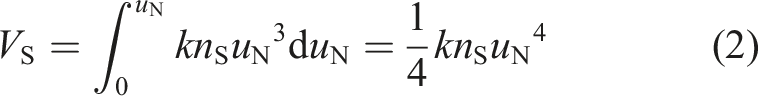
A double-beam system supported by a spring-mass system that is nonlinear is established in Figure 1, where the supporting nonlinearity is artificially introduced. For engineering practice, parameters of the supporting nonlinearity can be tested before installing it into the double-beam system. The double-beam system explained in Figure 1 consists of 2 beam segments (Beam I and Beam II), boundary supports, a coupling element, and nonlinear support. E1, L1, D1, CB1, ρ1, mA, and u1(x1,t) are elastic modulus, length, diameter, viscous damping, mass density, additional mass, and transverse vibration displacement of Beam I. E2, L2, D2, CB2, ρ2, and u2(x2,t) are elastic modulus, length, diameter, viscous damping, mass density, and transverse vibration displacement of Beam II. Boundary-supporting springs are introduced to simulate boundary conditions of the beam system. kL, kI, and kR are the corresponding translational stiffness coefficient while KL, KI, and KR are the corresponding rotational stiffness coefficients. kE is the stiffness coefficient of the coupling element. The supporting nonlinearity is composed of concentrated mass (mS), viscous damping (CS), linear stiffness (kS), and nonlinear stiffness (knS). xS is the position of the supporting nonlinearity. The uN(t) is defined as the displacement of the supporting nonlinearity. For this study, the nonlinear stiffness of the nonlinear support is regarded as cubic stiffness, which can be easily realized through mechanism design. Therefore, the nonlinear restoring force of the nonlinear support can be derived as The physical model of a beam system with a nonlinear support.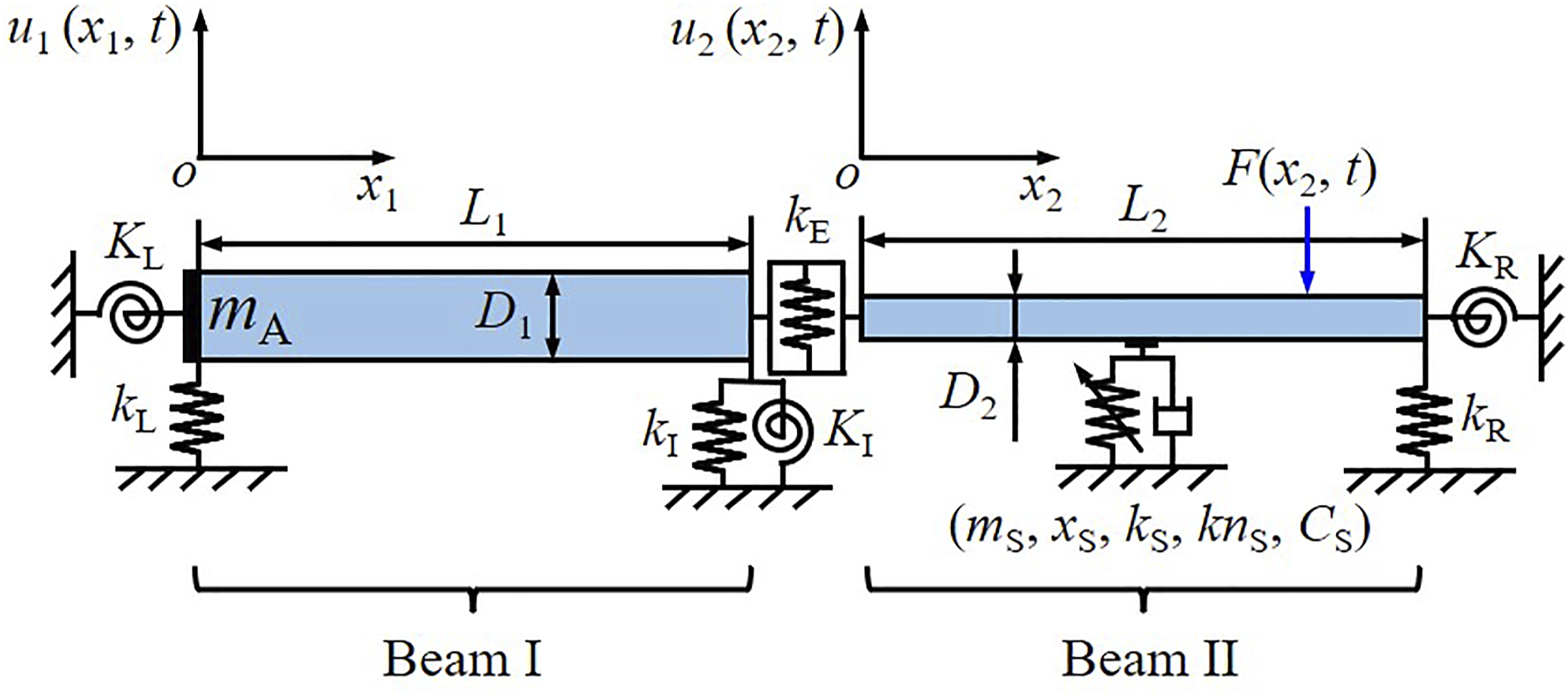

The potential energy of the supporting nonlinearity introduced by the nonlinear restoring force can be derived as

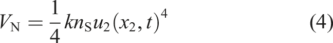
Then, equation (2) can be changed as
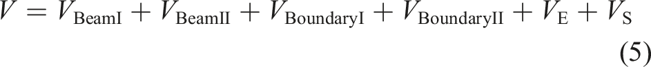
From the energy principles and laws, the potential energy of such a double-beam system can be derived as
The beam system’s kinetic energy may be calculated as

The virtual work of the beam system is given as

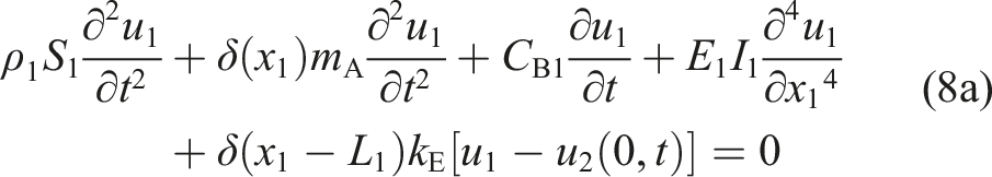
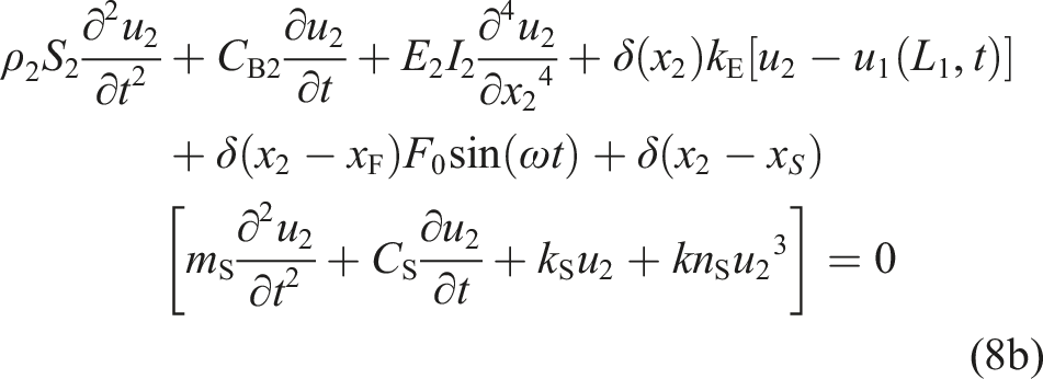
Using the variational method and the generalized Hamiltonian method, we can find the governing equations for a double-beam system involving nonlinear support. The corresponding terms are given in Appendix B. The specific expressions of system governing equations are written as
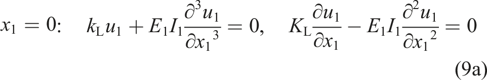
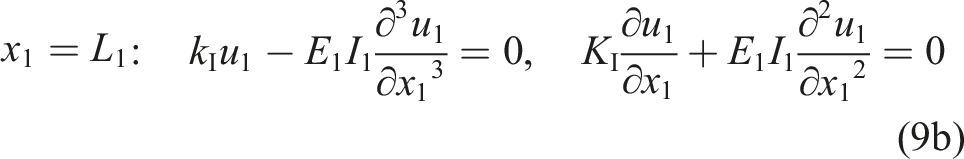
Boundary conditions of Beam I are derived as
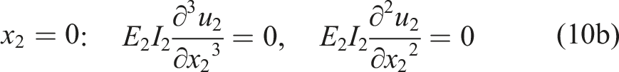
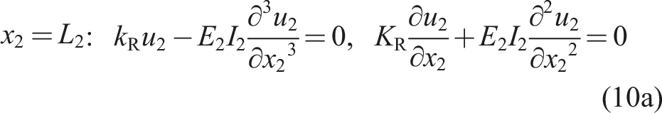
Boundary conditions of Beam II are given as
2.2. Solution procedure
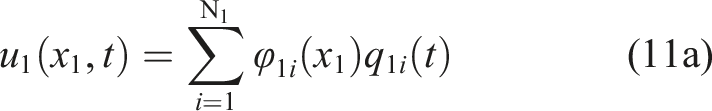
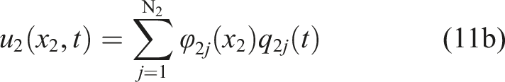
For the general equations derived in Section 2.1, the GTM is employed to establish their residual equations. Nonlinear dynamic responses of the double-beam system can be predicted by numerically solving the corresponding residual equations. The transverse vibration displacement is expanded as,
By utilizing the Galerkin discretization condition, the residual equations of such a double-beam system are derived as
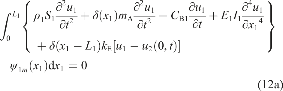
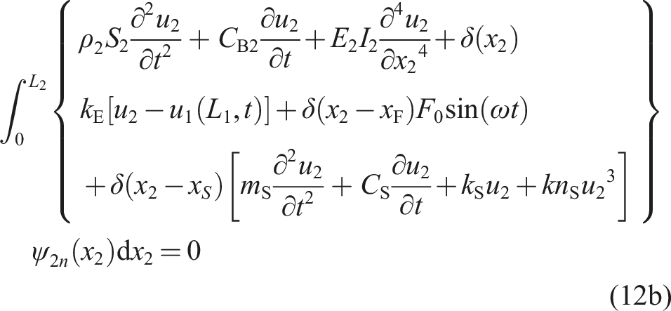
By putting the terms linked to the consequent derivate of time into one side, equation (12) can be rederived as,
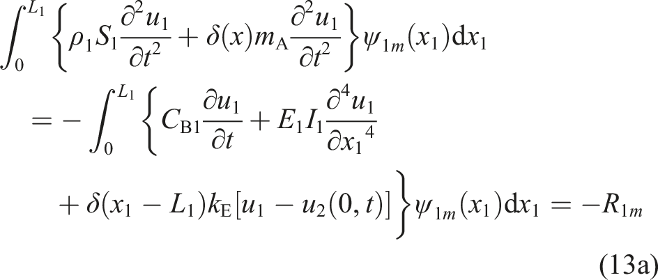
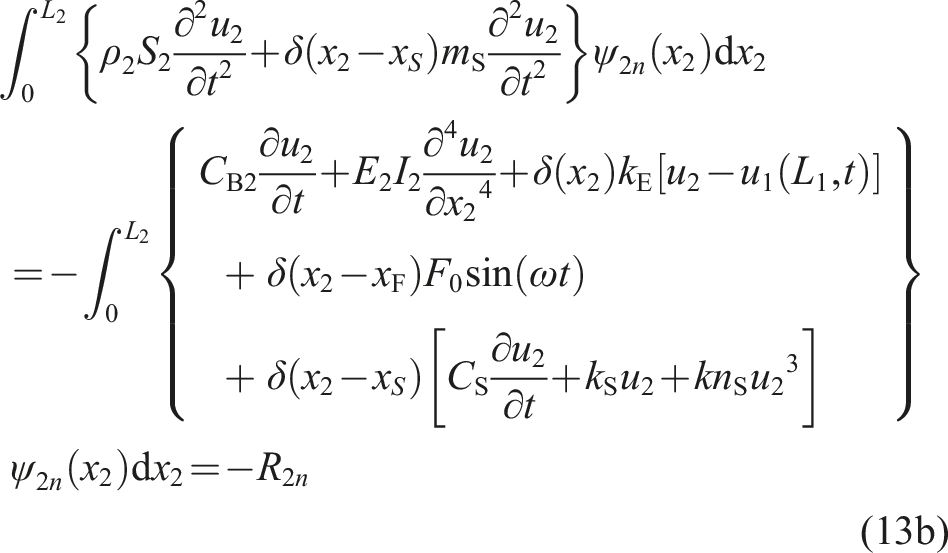
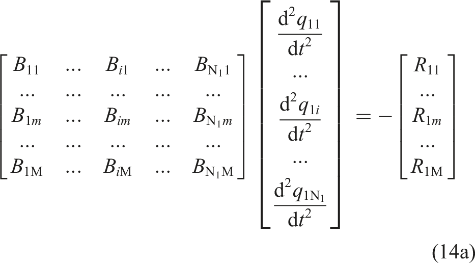
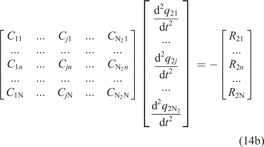
Replacing equation (11) into equation (13) and placing residual equations into a matrix form, residual equations in a matrix form of Beam I and Beam II can be derived as
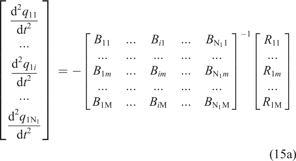
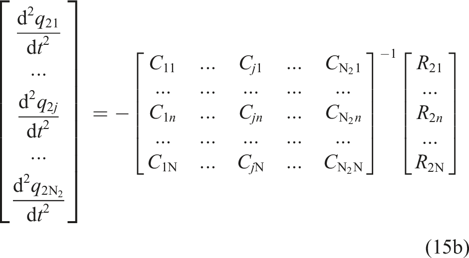
Equation (15) can be solved directly by employing numerical methods. Putting the calculation results into equation (11), nonlinear dynamic responses of the double-beam system can be obtained. The Runge-Kutta technique is utilized to solve equation (15). Furthermore, for elastic structures with other elastic nonlinearities, the GTM can also be employed to predict their dynamic responses.
3. Numerical results and discussion
3.1. Validation of the dynamic responses
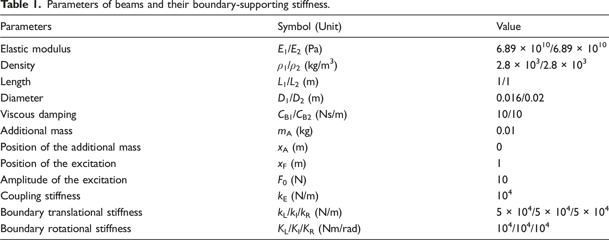
Parameters of beams and their boundary-supporting stiffness.
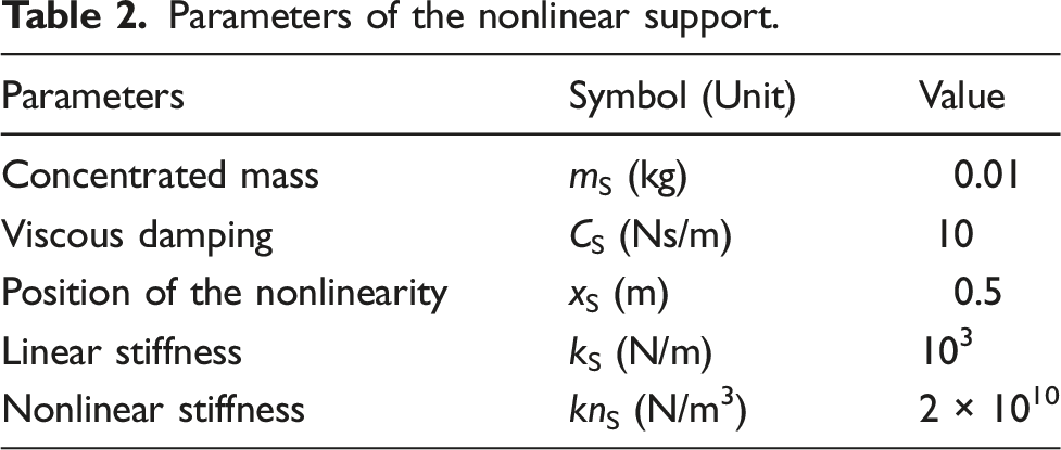
Parameters of the nonlinear support.
The theoretical analysis studied in Section 2 is programmed in a simulation platform (MATLAB). The integral process in Section 2.2 is realized by employing the int command. The ODE45 command is employed to calculate the residual equations established in Section 2.2. In calculating the residual equations, the 0∼500 TE is selected as the time calculation domain, where TE is the duration of the external excitation force. To ensure the transient responses of the beam system dies away, nonlinear dynamic responses of the double-beam system in 401∼500 TE are considered stable. Furthermore, select 50 calculation points for each time-domain calculation period.
Considering the nonlinear restoring force of the supporting nonlinearity is proportional to the u2(xS,t)3, the supporting nonlinearity will mainly influence dynamic responses of the double-beam system under their primary resonance regions. In the process of the GTM, natural frequencies of Beam I and Beam II can be obtained. The first three-order natural frequencies of Beam I are 48.7 Hz, 93.4 Hz, and 159.6 Hz, while the first three-order natural frequencies of Beam II are 12.1 Hz, 54.2, and 130.8 Hz. To study the dynamic responses of the double-beam system under the first three-order primary resonance regions, the frequency range of the external excitation is chosen as 1 Hz–200 Hz.
First, the correctness of the GTM in foretelling the nonlinear dynamic responses of a double-beam system with a spring-mass system that is nonlinear is investigated. To ensure the unknown coefficients equal to the number of equations, the relation of N1, N2, N, and M are set as N1 = M and N2 = N. N1 and N2 can be set as different values in GTM. To simplify the solution process of the GTM, N1 and N2 are set to the same value. Considering the displacement expression assumed in Section 2.2, the GTM is checked for accuracy using the HBM and Lagrange method (LM). In HBM, the time terms are set as fundamental. In LM, the Lagrange function is employed to build the matrix equation of the double-beam system with nonlinear support.
Figure 2 presents the amplitude–frequency responses of the double-beam system with nonlinear support predicted by the GTM, HBM, and LM. It should be noticed that the modeling method of the GTM and LM is quite different, where the GTM derives the residual equations from the governing equation of the double-beam system while the LM derives the matrix equation of the double-beam system from the Lagrange function. It is important to note that although the GTM and LM perform their analysis of the beam system’s amplitude–frequency responses in the time domain, the HBM performs its analysis in the frequency domain. Amplitude–frequency responses foreseen by the GTM, HBM, and LM resonate with each other well, where the max relative error of these methods is less than 5%. The above phenomenon verifies the correctness of GTM in predicting the dynamic responses of the double-beam system with nonlinear support. Amplitude-frequency responses predicted by the Galerkin truncation method, harmonic balance method, and Lagrange method (a) x1 = 0 (b) x1 = L1 (c) x2 = 0 (d) x2 = L2.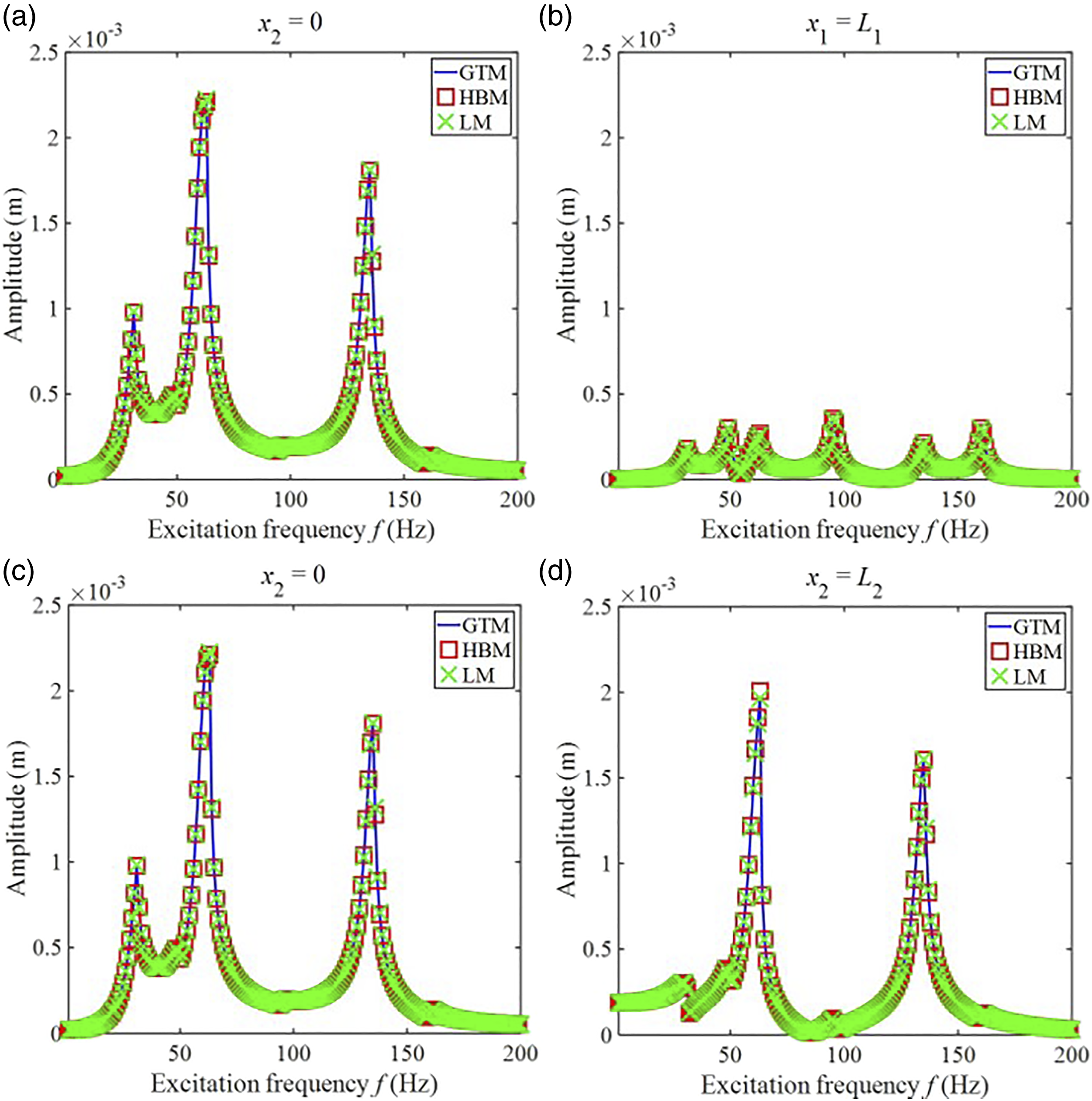
Second, the effect of the truncation numbers on the GTM is investigated. Amplitude-frequency responses under different truncation numbers are graphed in Figure 3. When the truncation number is 2-term, two primary resonance regions are seen in amplitude–frequency responses. When the truncation numbers are 4-term, 6-term, and 8-term, four primary resonance regions are appearing in amplitude-frequency responses. The above phenomenon indicates that the truncation number can influence the number of the primary resonance region. Furthermore, as the truncation number exceeds 6-term, amplitude-frequency responses of the beam system keep stable. In the following research, the truncation number of the GTM is set as 6-term. Furthermore, the peak amplitudes in Figure 3(a) and 3(b) are small but the peak amplitudes are high in Figure 3(c) and 3(d). The reason for such a phenomenon is that the coupling stiffness between Beam I and Beam II is relatively soft, causing the force transferred from Beam II to Beam I to be relatively small. When the coupling stiffness becomes harder, the peak amplitudes of Beam I increase significantly. Amplitude–frequency responses under different truncation numbers (a) x1 = 0 (b) x1 = L1 (c) x2 = 0 (d) x2 = L2.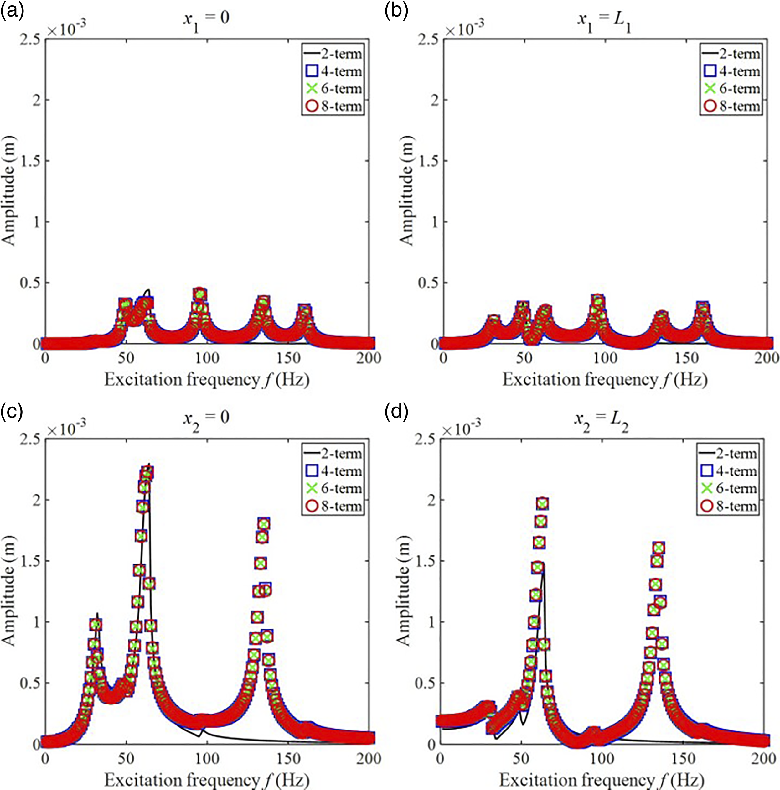
Third, the influence of initial calculation values of the GTM on amplitude–frequency responses of the double-beam system is studied. Figure 4 presents the amplitude–frequency responses under reverse and forward sweeping techniques, where the excitation frequency of the forward sweeping way ranges from 1 Hz to 200 Hz while the excitation frequency of the reverse sweeping way ranges from 200 Hz to 1 Hz. In the above sweeping ways, the initial calculation values of the current excitation frequency are the stable values of the last excitation frequency. Figure 4 shows that the double-beam system utilizing nonlinear support results in a sweeping disparity in amplitude–frequency responses. For the forward sweeping way, the peak-jumping phenomenon appears at 71 Hz. For the reverse sweeping way, the peak-jumping phenomenon appears at 65 Hz. Such a scenario suggests that amplitude–frequency responses of the beam system with nonlinear support are subtle to their previous calculation values. Amplitude–frequency responses under different sweeping ways (a) x1 = 0 (b) x1 = L1 (c) x2 = 0 (d) x2 = L2.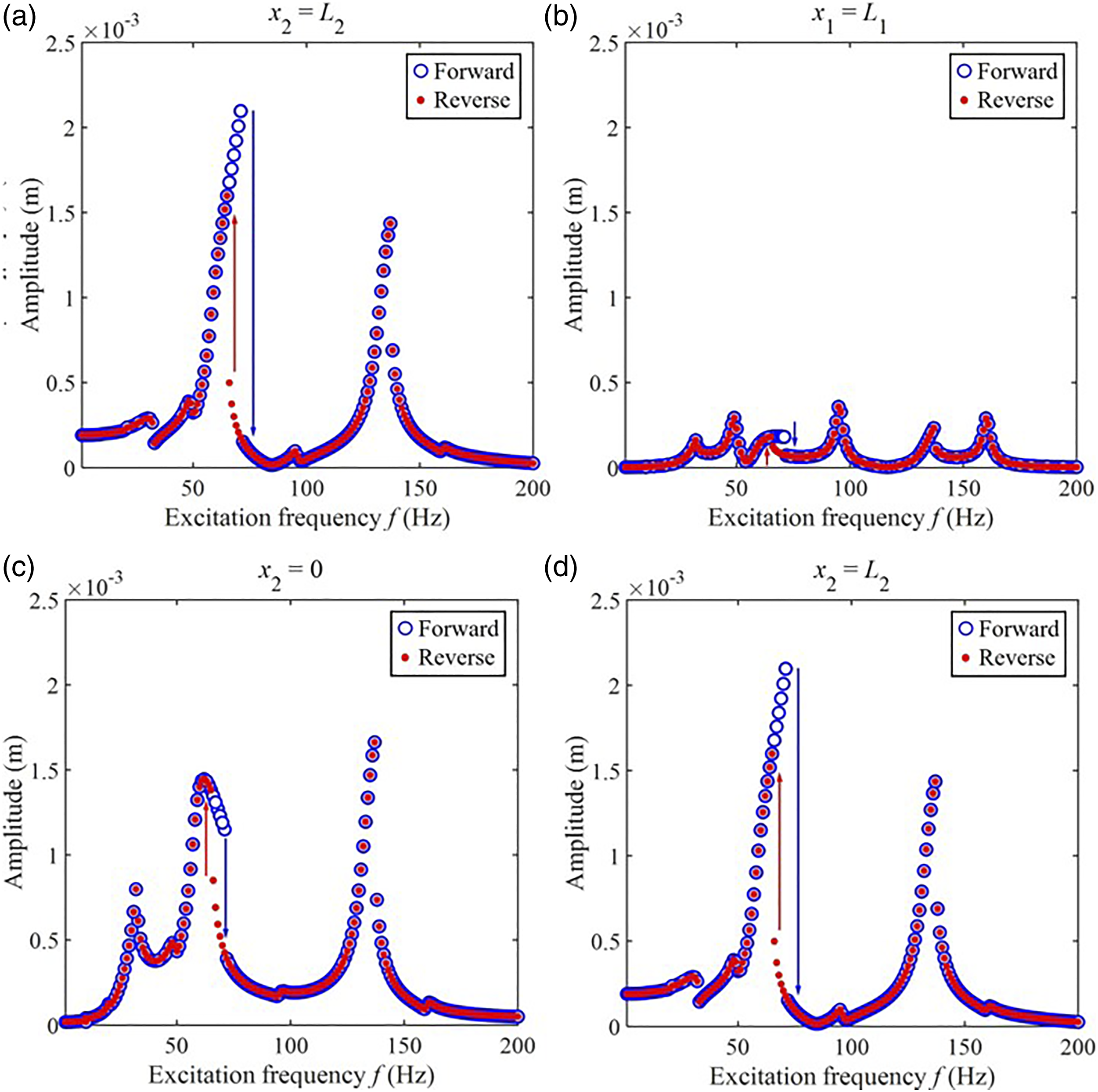
3.2. Amplitude–frequency responses influenced by the nonlinear support
This section investigates the impact of nonlinear support on amplitude–frequency responses of the double-beam system. Considering the engineering practice, the installation of the nonlinear support depends on the residual space of the double-beam system. Therefore, this part studies the impact of knS, CS, and mS of nonlinear support on amplitude-frequency responses of the double-beam system. In this section, the initial calculation values of the GTM are set as the constant.
First, Figure 5 depicts the amplitude–frequency responses of the double-beam system equipped with nonlinear support at varying knS. According to Figure 5, when knS is increased in comparison to the amplitude–frequency responses of the double-beam system without knS, vibration suppression occurs at the second and third primary resonance zones. Unsuitable knS motivates the complex dynamic actions of the double-beam system. Furthermore, primary resonance regions of the double-beam system shift to higher frequency regions with the increase of knS. Phase diagrams are plotted to evaluate the complex dynamic behavior of the double-beam system. In each subfigure of Figure 5, Poincare points create a closed curve and the phase path maintains stability, indicating that the complicated dynamic behavior shown in Figure 5 is vibrating in a quasi-periodic condition. Amplitude–frequency responses under different knS (a) x1 = 0 (b) x1 = L1 (c) x2 = 0 (d) x2 = L2.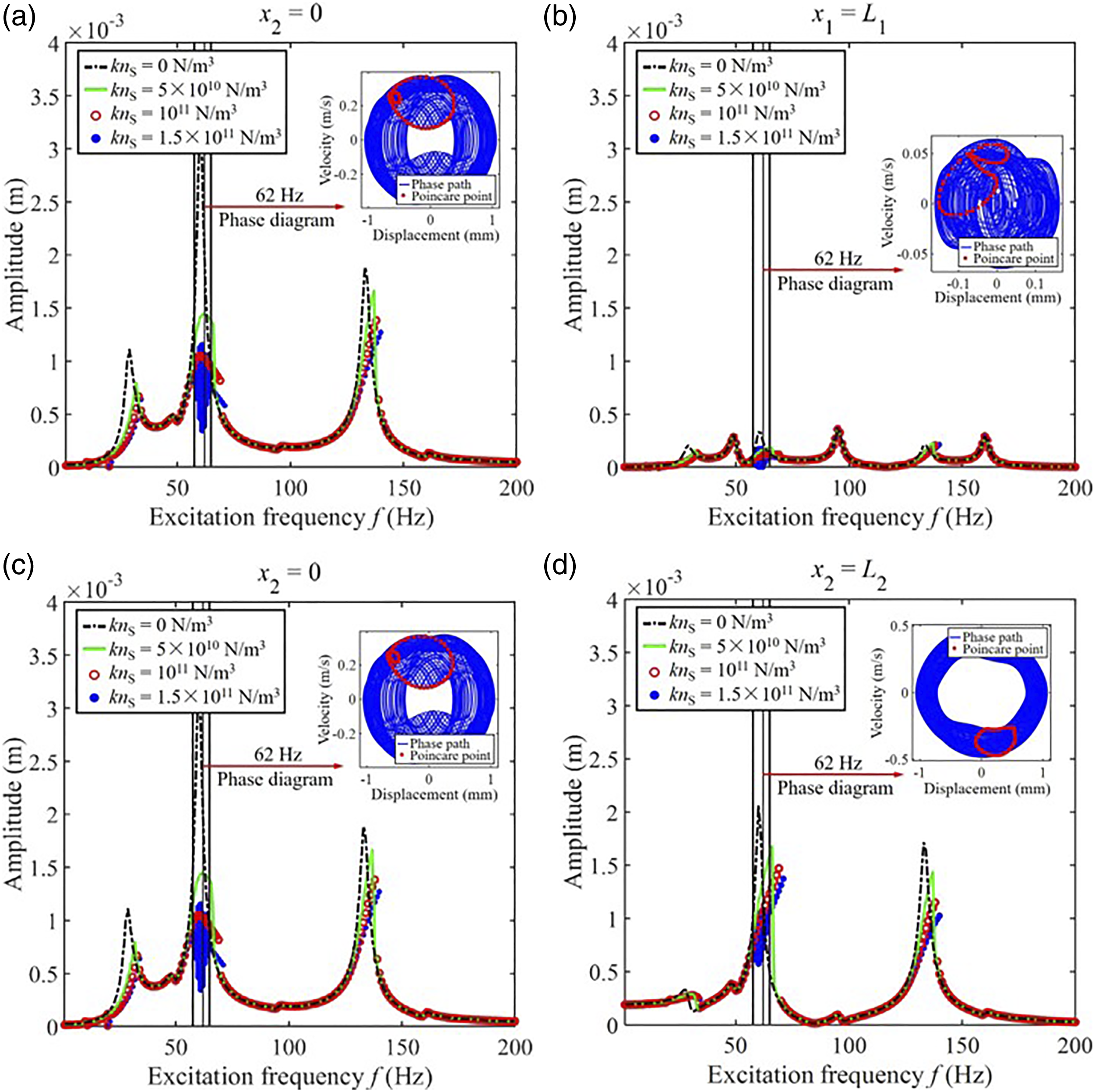
Second, Figure 6 shows the amplitude–frequency responses of the double-beam system with nonlinear support under different CS. From Figure 6, when the value of CS is small, complex dynamic responses of the beam system appear in Figure 6. Phase diagrams of such complex dynamic responses are plotted. Following the subfigures in Figure 6, Poincare points form a closed curve, which indicates that the complex dynamic responses in Figure 6 are in the quasi-periodic condition. Furthermore, with the consistent increase of CS, the above complex behavior of the double-beam system gradually disappears. The increase of CS beneficially influences vibration suppression at the 2nd and 3rd primary resonance regions in amplitude–frequency responses of the double-beam system with nonlinear support. Amplitude–frequency responses under different CS (a) x1 = 0 (b) x1 = L1 (c) x2 = 0 (d) x2 = L2.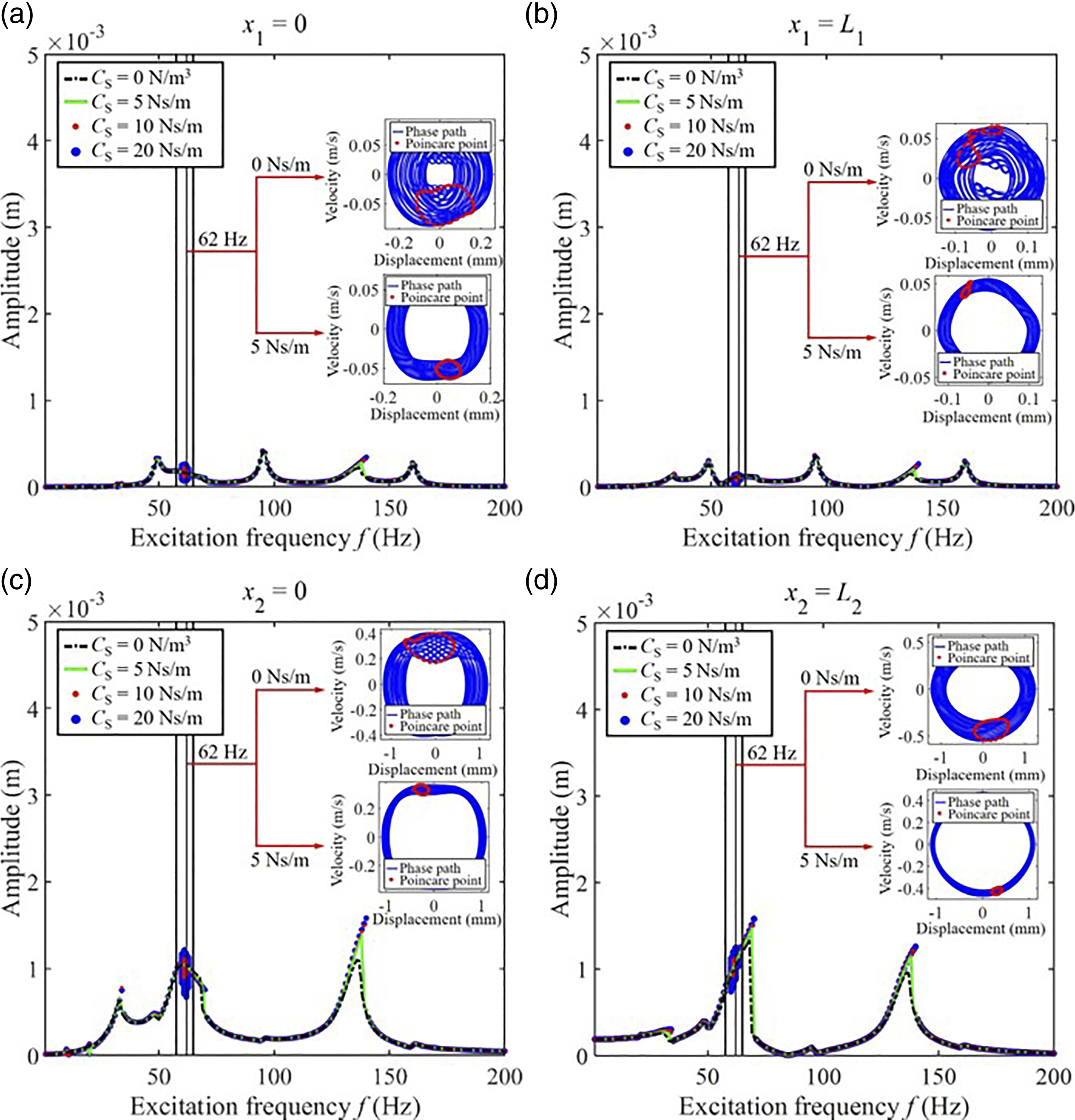
Third, Figure 7 presents the amplitude–frequency responses of the double-beam system with nonlinear support under different mS. From Figure 7, the increase of mS harmfully influences vibration suppression at the 2nd and 3rd primary resonance regions in amplitude–frequency responses of the beam system with nonlinear support. With the consistent increase of mS, complex dynamic responses of the beam system gradually appear in amplitude-frequency responses. Phase diagrams of such complex dynamic responses are plotted. Poincare points in a phase diagram form a closed curve. The complicated dynamic reactions in Figure 7 exhibit quasi-periodic behavior under these conditions. Amplitude–frequency responses under different mS (a) x1 = 0 (b) x1 = L1 (c) x2 = 0 (d) x2 = L2.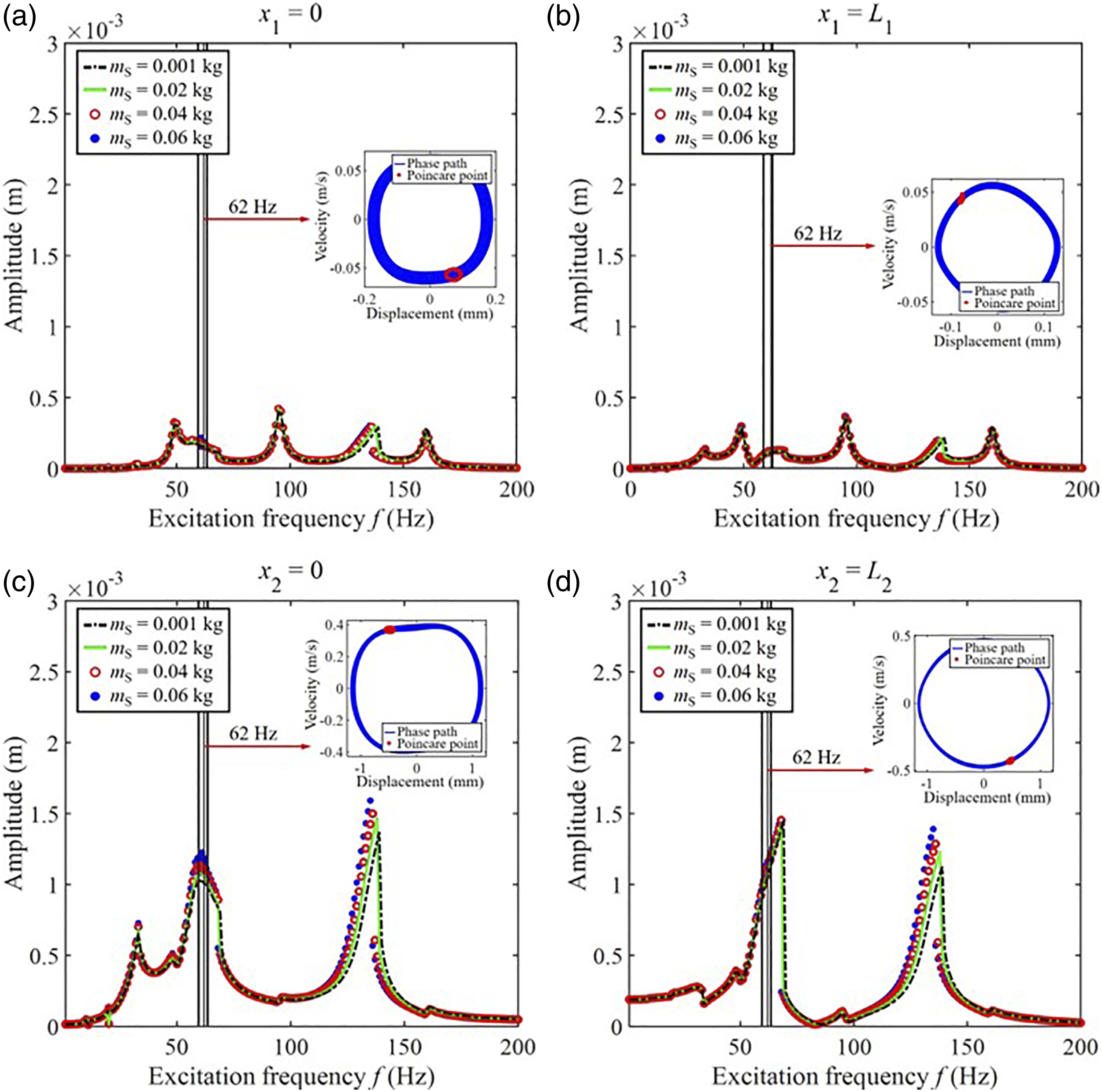
3.3. Single-frequency responses influenced by the nonlinear support
This section studies the impact of a mass-spring system that is nonlinear on single-frequency responses of a beam system. Similar to the research in Section 3.2, this part studies the impact of knS, CS, and mS of the nonlinear support on single-frequency responses. The external excitation force is set as F0 = 20 N and f = 45 Hz.
First, Figure 8 presents the amplitude-knS responses of the double-beam system with nonlinear support under a single-frequency excitation. Increasing kns has a positive effect on dampening vibrations at the boundary of Beam I and at the left boundary of Beam II, as shown in Figure 8. With the consistent increase of knS, the complex dynamic behavior of the double-beam system appears. Furthermore, the amplitude rising phenomenon appears in Figure 8(b) when knS exceeds more than 2 × 10¹¹ N/m3. The reason for such a phenomenon is that the primary resonance region of the double-beam system shifts to a higher frequency region as the increase of knS. However, the shifting phenomenon of the primary resonance region will not be directly reflected in single-frequency responses. The above shifting phenomenon of the primary resonance region motivates the variation of the amplitude in single-frequency responses. Therefore, the amplitude rising phenomenon appears in Figure 8(b) when knS exceeds more than 2 × 10¹¹ N/m3. Vibration waveforms and phase diagrams under the complex dynamic behavior are plotted. Following the wave types of vibration and the phase diagrams, a closed Poincare point curve presents in each phase diagram and vibration waveforms are stable. Such a phenomenon suggests that the complex dynamic behavior in Figure 8 presents a quasi-periodic state. Amplitude-knS responses under a single-frequency excitation (45 Hz) (a) x1 = 0 (b) x1 = L1 (c) x2 = 0 (d) x2 = L2.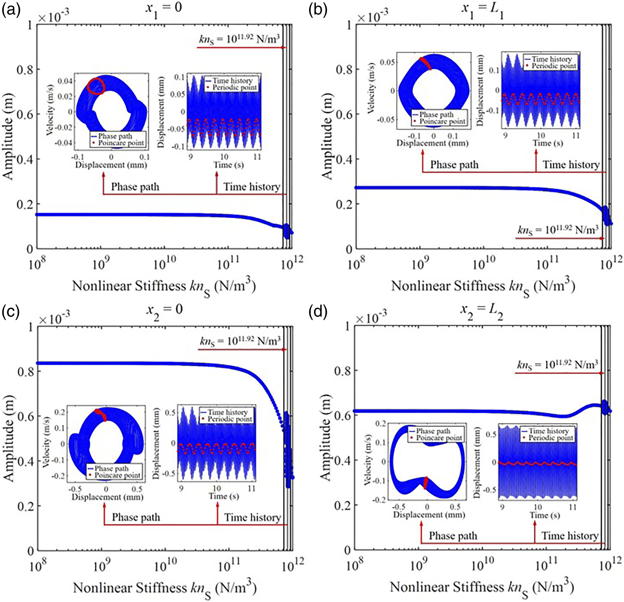
Second, Figure 9 presents the amplitude-CS responses of the double-beam system with nonlinear support under a single-frequency excitation. From Figure 9, when the value of CS stays small, complex dynamic responses of the double-beam system appear in amplitude-CS responses. With the consistent increase of CS, the complex dynamic behavior of the double-beam system gradually disappears. The explanation for such a phenomenon is that the nonlinear restoring force introduced by the nonlinear support is proportional to the u2(xS,t)3. The maximum value of displacement of the double-beam decreases with the increase of CS, suggesting that the nonlinear restoring force introduced by the nonlinear support also decreases. Furthermore, the amplitude of the nonlinear restoring force is positively correlated with the complex dynamic behavior of the double-beam system. Therefore, with the consistent increase of CS, the complex dynamic behavior of the double-beam system gradually disappears. Vibration waveforms and phase diagrams are plotted to further explore the complicated dynamic behavior described above. A closed Poincare point curve presents in each phase diagram and vibration waveforms are steady. One can conclude that the complex dynamic behavior depicted in Figure 9 exhibits a quasi-periodic condition. Amplitude-CS responses under a single-frequency excitation (45 Hz) (a) x1 = 0 (b) x1 = L1 (c) x2 = 0 (d) x2 = L2.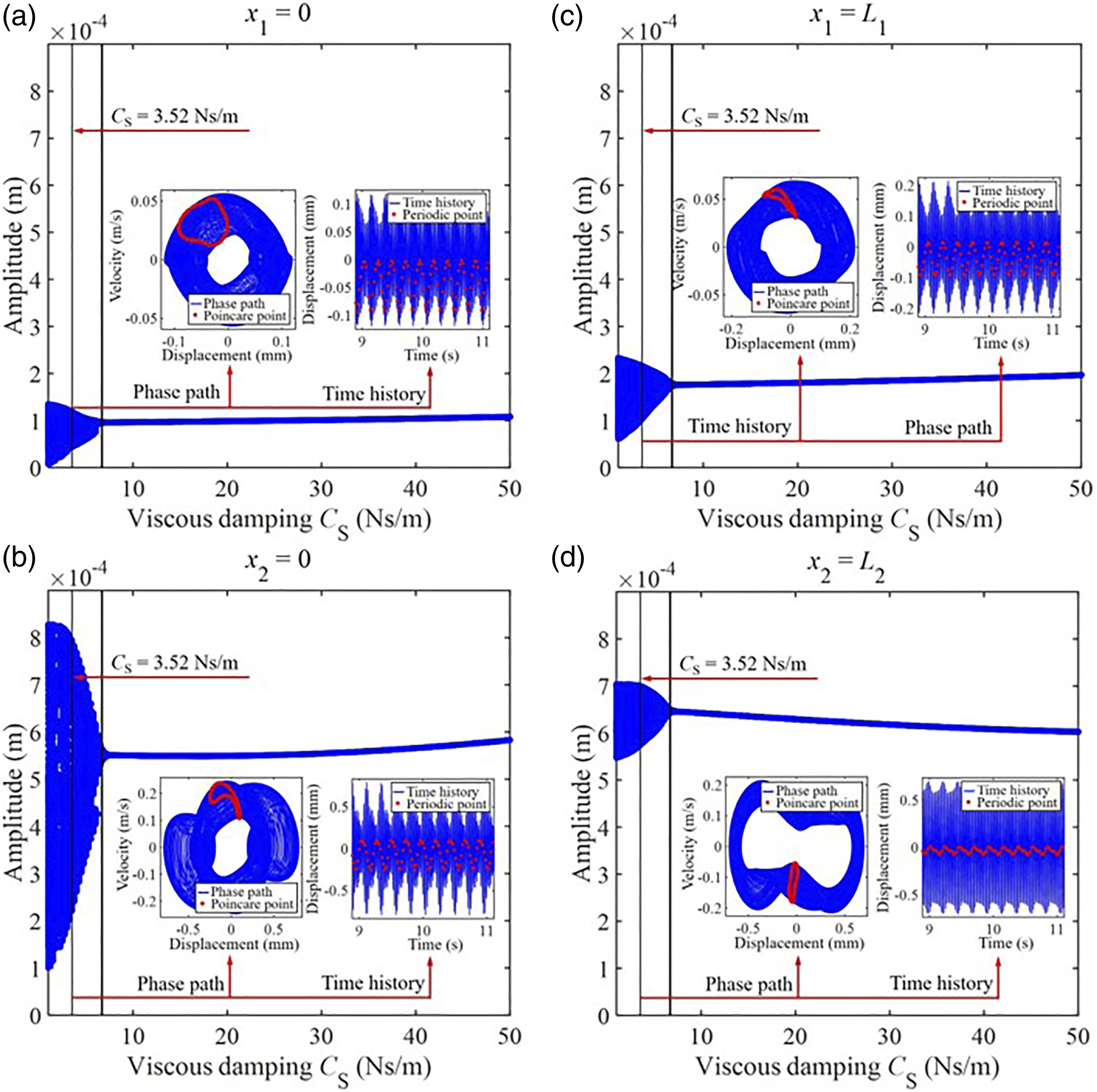
Third, Figure 10 presents the amplitude-mS responses of the double-beam system with nonlinear support under a single-frequency excitation. From Figure 10, the vibration at the boundary of the double-beam system changes slightly with the increase of mS. With the consistent increase of mS, the composite dynamic behavior of the double-beam system gradually appears. Phase diagrams and vibration waveforms are plotted to judge the vibration state of the complex dynamic behavior. Similar to the analysis in Figure 8 and Figure 9, the complicated dynamic behavior depicted in Figure 10 has a quasi-periodic vibration state. Amplitude-mS responses under a single-frequency excitation (45 Hz) (a) x1 = 0 (b) x1 = L1 (c) x2 = 0 (d) x2 = L2.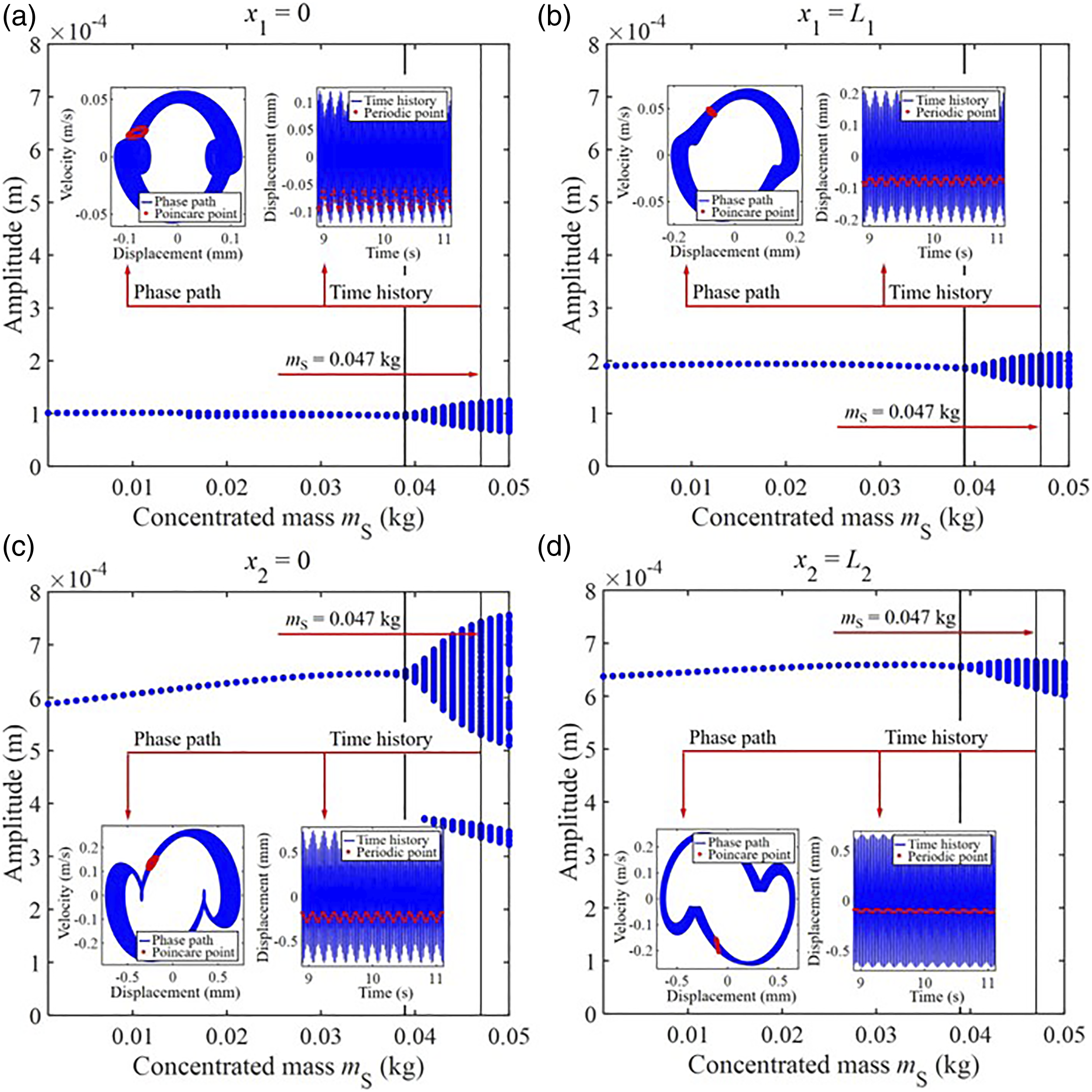
On most engineering occasions, the nonlinear support’s concentrated mass is dependent on its installation pattern. mS is hard to change once the installation form is determined. Putting into consideration the engineering action, the subsequent research investigates the optimization of beams with nonlinear support under a single-frequency excitation, where the optimization parameters are knS and CS.
Figure 11 is the optimization of beams with nonlinear support under a single-frequency excitation. From Figure 11, there is a suitable combination of knS and CS for vibration subduing at the boundary of the beam system. When knS = 1012 N/m3 and CS = 17.95 Ns/m, the vibration capacity at the left boundary of Beam I is effectively suppressed. As knS = 1012 N/m3 and CS = 0 Ns/m, the vibration at the right boundary of Beam I is effectively suppressed. When knS = 1012 N/m3 and CS = 35.89 Ns/m, the vibration at the left boundary of Beam II is effectively subdued. As knS = 6.87 × 10¹¹ N/m3 and CS = 0 Ns/m, the vibration at the right boundary of Beam II is subdued effectively. It should be noticed that the corresponding suitable combination of knS and CS is different for different observed points. Parameters optimization under a single-frequency excitation (45 Hz) (a) x1 = 0 (b) x1 = L1 (c) x2 = 0 (d) x2 = L2.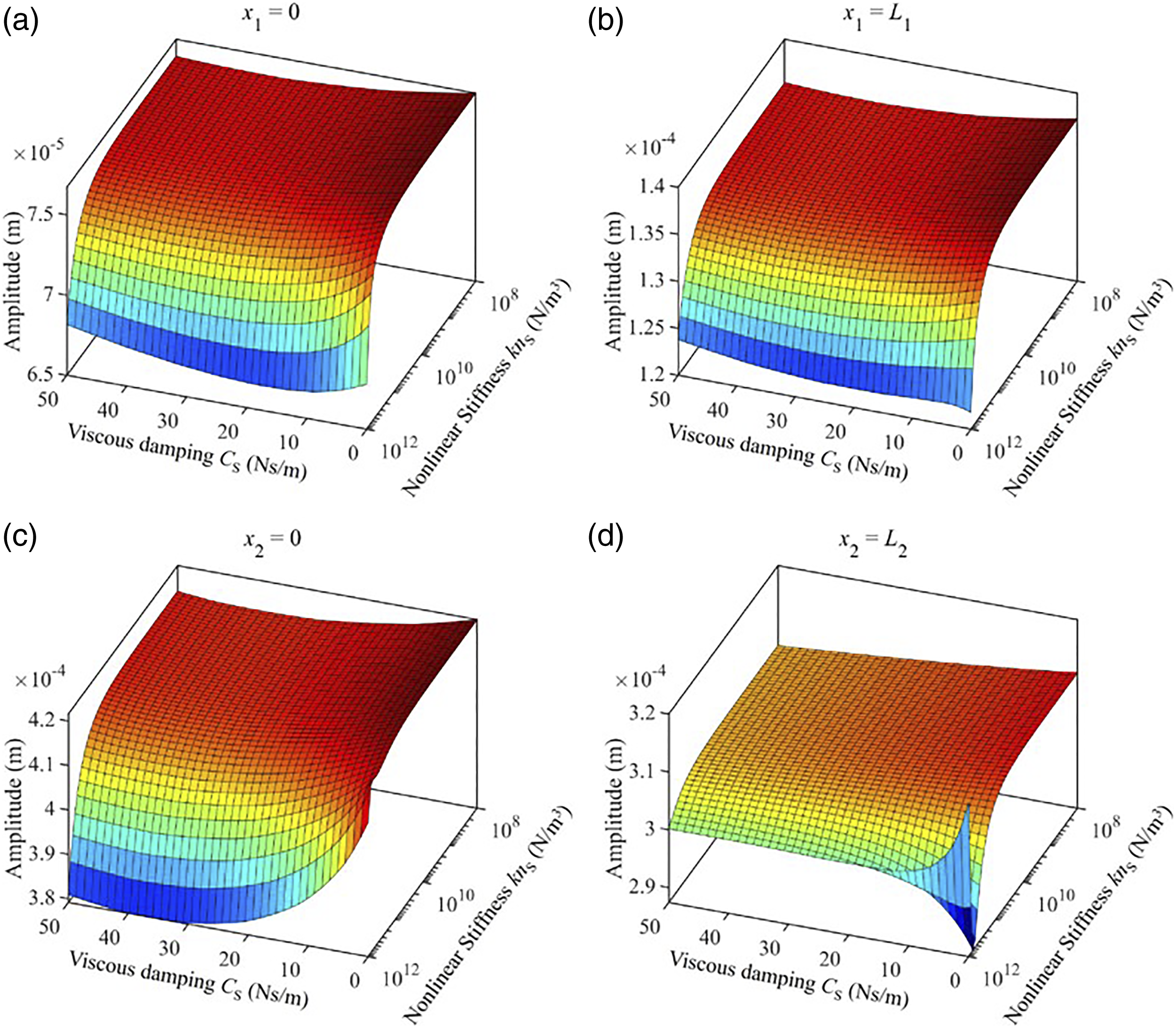
4. Conclusions
Through this study, the vibrational behavior analysis model of a double-beam structure with nonlinear support is presented. The governing equation of the above system is derived through the variational method combined with the generalized Hamiltonian method. The GTM is employed to predict the transverse forced vibration of the double-beam system. The HBM and LM are utilized to verify the correctness of the transverse forced vibration of the double-beam system obtained through the GTM. Based on this, investigating how the nonlinear support modifies both the amplitude-frequency responses and the single-frequency responses of the beam mechanism and some findings are drawn as, (1) The GTM can reliably forecast the transverse forced vibration of the double-beam system with a supporting nonlinear. In this study, the GTM is guaranteed to be solid down to a truncation number of 6 terms. Transverse forced vibration of the double-beam system with a support nonlinearity is sensitive to their previous calculation values. (2) Amplitude-frequency responses and single-frequency responses of the double-beam system are both significantly influenced by knS, CS, and mS of the nonlinear support. For the parameters of beams in this study, changing the parameters of nonlinear support can transform the vibration states of the double-beam system with a supporting nonlinearity effectively. (3) Suitable parameters of the nonlinear support effectively suppress the double-beam system’s vibration level at the boundary. Unsuitable parameters of the nonlinear support stimulate the complex dynamic responses of the double-beam system and hurt vibration suppression at the boundary of the double-beam system. (4) For the double-beam system under a single-frequency excitation, there is a suitable combination of knS and CS for the vibration subduing at the boundary of the double-beam system, where the corresponding suitable combination is different for different observing points. On the whole, the supporting nonlinearity has the potential application value in vibration suppression of the double-beam system subjected to transverse forced vibration.
Footnotes
Declaration of conflicting interests
The author(s) declared no potential conflicts of interest with respect to the research, authorship, and/or publication of this article.
Funding
The author(s) disclosed receipt of the following financial support for the research, authorship, and/or publication of this article: This work is supported by the National Natural Science Foundation of China (Grant no. 11972125) and the Fok Ying Tung Education Foundation (Grant no. 161049).
Author’s Note
The datasets generated during and/or analyzed during the current study are available from the corresponding author on reasonable request.
Appendix A
Appendix B