
Abstract
Noise reduction is very important for cavities such as long ventilation ducts, and train and airplane cabins. This paper seeks to develop, design, and implement an active noise control system to globally reduce narrowband and broadband acoustic noises inside a cylindrical cavity using the Modal FxLMS algorithm along with canceling the feedback effect of the actuator on the reference microphone. In addition, the efficiency of the proposed algorithm is compared to the conventional FxLMS algorithm for broadband noises in terms of acoustic potential energy and energy consumption of the actuators. To this end, the natural frequencies and mode shapes are derived using experimental methods and finite element simulation, and the results are compared. The modal data are used to design and implement a modal filter. The filter output is fed to the Modal FxLMS algorithm as the error signal for updating controller coefficients. Due to the presence of a reference microphone for the proposed algorithm and the effect of the control loudspeaker, it is required to remove the feedback effect. An experimental setup is developed, and an FPGA board and LabVIEW software are adopted to implement and verify the effectiveness of the proposed algorithm. The results indicate that the controller could effectively attenuate the narrowband and broadband acoustic noises globally. Furthermore, although the conventional FxLMS algorithm can suppress the noise around acoustic modes, it produces a larger control signal than the Modal FxLMS algorithm and consumes more energy.
1. Introduction
Noise pollution caused by vehicles such as cars, trains, and airplanes has gained the attention of researchers for a few decades. It is prevalent to use lighter and thinner materials in such vehicles to decrease fuel consumption and production costs, which has led to higher noise transmission inside the cabin. Therefore, it is necessary to reduce the noise inside the cabin using noise control methods to provide sufficient comfort for the passengers. Acoustical absorbers and barriers are passively used to reduce acoustic noise. Absorbers are porous materials that absorb sound energy, while barriers are dense materials reflecting the sound and preventing sound propagation. In passive methods, it is required that the absorber or barrier depth be thick enough depending on the desired frequency to diminish the sound effectively (Tavakkoli Nejad et al., 2020; Vér, 2005). Thus, passive methods are effective for frequencies higher than 1 kHz.
For lower frequencies, active noise control (ANC) can be a solution. The active methods use acoustic or vibratory actuators to generate an out-of-phase acoustic signal relative to the disturbance. Hence, two signals cancel each other, and the noise is reduced (Kuo and Morgan, 1995). One of the most popular approaches is the LMS adaptive algorithm. Many modified LMS algorithms have been developed by researchers for different situations and conditions. Leaky FxLMS (Wu et al., 2018), filtered-u LMS (Kim et al., 2011), filtered-x generalized mixed norm (Song and Zhao, 2018), normalized filtered-x LMS (Zhang et al., 2019), and FxLMS algorithm with recursive prediction error (Zheng et al., 2020) are some examples of the modified LMS approaches.
Controlling the noise is not merely canceling the acoustic disturbance. In some applications, regulating the amplitude of the sound pressure or adjusting the frequency content of the sound is required. The former and latter methods are referred to as the active noise equalizer (ANE) and active sound profiling (ASP), respectively. Wang et al. (Wang et al., 2018a) developed an ASP algorithm in a time–frequency domain to actively control the time-varying noises of a gasoline engine. Wang et al. (2019) proposed the ASS-LMS method for sound quality control along with online secondary path modeling. Improving the sound quality of the noise instead of suppressing the amplitude of the noise is another approach that some researchers investigated. In this method, the purpose of the controller is to improve the pleasantness of the sound that can be assessed by two methods: first by using Jury tests and second by prediction based on loudness, sharpness, roughness, and tonality indices (Gonzalez et al., 2003).
ANC could be implemented using analog or digital approaches. Although analog implementation does not require digital signal processors, it is less popular due to its lower flexibility. The digital implementation of ANC systems is usually carried out by digital signal processors (DSPs) (Kuo and Morgan, 1995). However, FPGA could be an alternative solution for cases where high calculation speed or parallel processing is considered. Leva and Piroddi (2011) used an FPGA embedded board to implement a narrowband FxLMS algorithm.
ANC can also be implemented locally or globally. For local ANC, the aim is to mitigate the noise in a small space around the microphones; however, the global ANC aims to minimize the noise in a large space. ANC can be categorized based on the environment in which the noise is propagated, inside a cavity and outside a cavity. For example, the ANC inside a duct can be used to decrease acoustic noise along the ventilation ducts (Gardonio and Rohlfing, 2014), the ANC inside a cavity is adopted to reduce the road noise transmitted into the vehicle cabin (Wang et al., 2018b) and inside a small room (Aslan and Paurobally, 2018), and the ANC outside a cavity seeks to suppress the noise emitted from a structure to a larger space (Gohari et al., 2020; Loghmani et al., 2016a, 2016b).
The local ANC method could be employed to reduce the acoustic noise inside a cabin. Jung et al. (Jung et al., 2019) used multichannel ANC to decrease the local road acoustic disturbance. They used the remote microphone method to estimate the acoustic pressure inside a cabin. They also introduced the delayed remote microphone method to solve the causality problem inside the cavity. Akraminia and Mahjoob (Akraminia and Mahjoob, 2014) proposed an algorithm based on the FxLMS and wavelet transform to reduce the local noise inside a duct. Global ANC could reduce the sound pressure inside the whole cavity. One of the global ANC challenges is the selection of a proper acoustic parameter which should be minimized.
Pury et al. (Puri et al., 2018, 2019a, 2019b) proposed a new algorithm named Modal FxLMS to globally attenuate the harmonic acoustic noise inside a vibroacoustic cavity. This approach introduces a new concept called the modal secondary path. They simulated the suggested method on cavities such as car cabins using the finite element method (FEM) and implemented the proposed method on a cavity. To evaluate the algorithm performance, the acoustic potential energy inside the cavity was estimated using the virtual sensing method. It was observed that the Modal FxLMS algorithm globally reduces the narrowband acoustic noise inside the cavity in addition to a reduction in computational costs compared with the multichannel FxLMS algorithm. However, in their study, the broadband acoustic noise attenuation was not executed, while in many applications, the disturbance is broadband and some challenges such as feedback effects on the reference sensor could lead to system instability.
The present study has developed the broadband Modal FxLMS (BM-FxLMS) algorithm to globally reduce the acoustic potential energy inside a cylindrical cavity. The main difference between the narrowband and broadband Modal FxLMS is that in the latter one, the reference microphone is affected by the control loudspeaker; thus, this feedback effect should be canceled through the algorithm. Another important difference is that in the narrowband algorithm, the disturbance signal is the simple harmonic; therefore, just two coefficients for the filters are sufficient. However, the broadband disturbance requires the BM-FxLMS algorithm to have much more filter length; thus, the system is subject to non-causality. Therefore, the broadband disturbance, causality, and feedback effect are the challenges that should be considered in this algorithm. The efficiency of the proposed method has been validated using experimental tests. In the developed algorithm, the feedback effect on the reference sensor caused by the control loudspeaker is eliminated, and by implementing the algorithm on the FPGA board, the noise is decreased globally inside the cavity. In Section 2, first, the formulation of the BM-FxLMS method with the schemes of deriving the required modal parameters is presented. Section 3 introduces the experimental setup, and in Section 4, the results of the proposed algorithm for controlling the broadband and narrowband noises around one and two acoustic modes are presented, and the results have been compared with the conventional FxLMS method. Section 5 concludes this paper.
2. Background theory
In the BM-FxLMS method, the purpose is to globally reduce the acoustic noise inside the cavity, and the acoustic potential energy is considered as a parameter that should reach its minimum value. In this section, some relations are presented to estimate the potential energy inside the cavity. Furthermore, BM-FxLMS formulations are derived to decrease the acoustic potential energy.
2.1. Broadband Modal FxLMS formulation
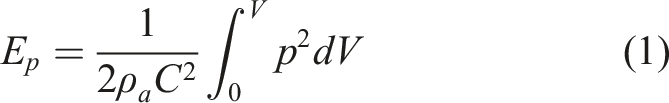
The acoustic potential energy inside the cavity is obtained by the following relation


The walls of the cavity are assumed to be rigid. Therefore, the wall vibration is neglected. Having this assumption, the sound pressure vector could be rewritten according to the modal parameters of the cavity


In other words
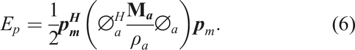
The term of

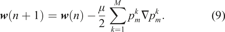
Now, using equation (7), an adaptive algorithm similar to the conventional FxLMS could be obtained so that it aims to reach the acoustic potential energy to its minimum value inside the cavity. Thus, the Modal FxLMS controller coefficients are updated as follows
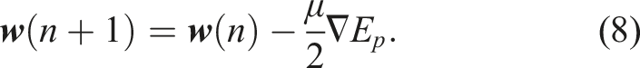
In equation (8),
The sound pressure in each node is the sum of the sound pressures from the disturbance (

If the k-th primary path is considered as the path impulse response from the noise source to k-th node and is named as


Therefore, the sound pressure in each node could be obtained as follows

By multiplying

As a result, this equation can be rewritten as


Regarding the fact that the gradient operator is defined based on the controller coefficients,

Using the commutative property of the convolution, this equation can be rewritten as

By applying the gradient operator, we have

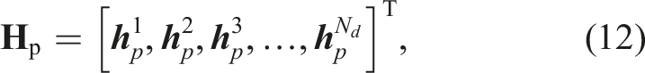
where
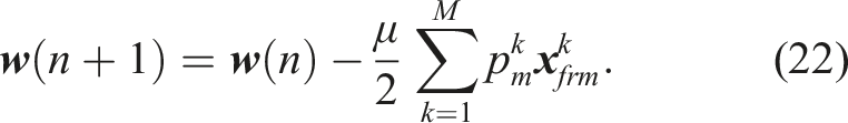
In equation (22),
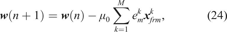
The microphone output voltage equals to the microphone sensitivity multiplied by the sound pressure. As a result, equation (14) can be rewritten as

where
The block diagram of the proposed controller is as Figure 1 where Block diagram of the BM-FxLMS with feedback cancellation.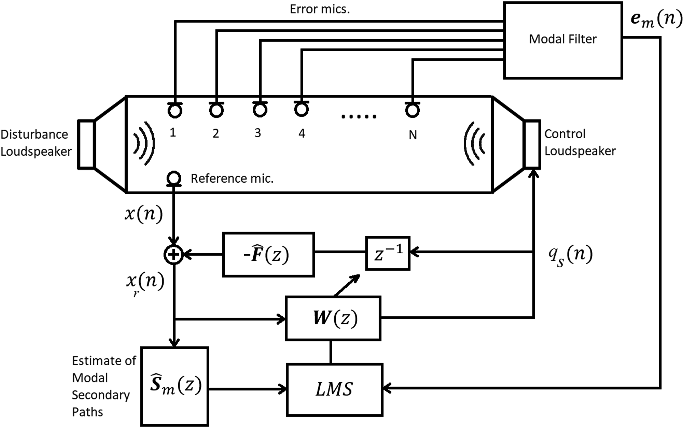

To cancel out this feedback effect and prevent diverging the algorithm, one can use

The modal filter in Figure 1 gives the sound pressure of the microphones and gives the modal error signal that is corresponding to the amplitude of the desired acoustic mode that the controller aims to suppress.
2.2. Comparison between the Modal FxLMS algorithms with narrowband and broadband noises
Based on the disturbance bandwidth, the ANC process is classified into narrowband and broadband sections. If the dominant acoustic noise is made up of one or several frequencies, the narrowband ANC is more efficient. However, if the dominant disturbance includes broadband frequencies, the broadband ANC should be performed.
The narrowband ANC works based on this principle that each pure sinusoidal signal with arbitrary phase and amplitude could be obtained as the summation of both sine and cosine signals with zero phases and known amplitude

In narrowband ANC with the FxLMS algorithm, for each frequency, a sinusoidal signal is used to generate the reference signal. In this method, based on equation (27), for each frequency, convergence is attainable by using two controller coefficients. In
Therefore, equation (24) can be rewritten to perform narrowband ANC using the modal method for the resonance frequency of
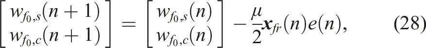
If the aim is to control more than one mode, it is necessary to choose the number of controller coefficients as twice the number of dominant modes in equation (30).
Despite the narrowband method, in the broadband approach, since a wide frequency band should be controlled, the number of controller coefficients becomes very great and depends on various parameters such as the distance between the control loudspeaker to the error microphone, cavity complexity, and the frequency bandwidth of the disturbance signal.
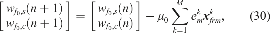
In broadband ANC by using the modal approach, equation (24) is used. If the ambient condition does not change much during the control procedure, the mode shape matrix and the secondary path remain constant, and this approach could be performed using the following seven steps: 1. Performing the modal test and evaluating matrix 2. Estimating the secondary path in the interested frequency band between the control loudspeaker and the error microphone and creating matrix 3. Computing the secondary modal path and creating matrix 4. Calculating output by utilizing convolution of the reference and controller signals. 5. Calculating the modal filtered reference signal ( 6. Updating the controller coefficients by equation (24). 7. Returning to step 4.
One of the differences between the broadband Modal FxLMS (BM-FxLMS) and narrowband Modal FxLMS (NM-FxLMS) methods is the fact that in the latter approach, the control loudspeaker does not have any effect on the reference sensor. Therefore, it is not required to eliminate the feedback effect. While in the former method, the feedback effect should be canceled. If not, it might lead to a divergent response of the controller.
3. Experimental setup
According to Figure 2, the experimental setup includes a PVC pipe with a length of 1 m and 0.11 m in diameter as the acoustic cylindrical cavity. Two loudspeakers were installed on both sides of the pipe as disturbance and controller sources. Seven electret microphones were attached to the pipe with 0.13 m distance from each other and a 0.11 m distance from both the pipe ends. The loudspeaker impedance and power are 8 Ω and 2W, respectively. Furthermore, a 5W class D stereo amplifier module was used to amplify the control signal to the loudspeakers. A Butterworth low-pass anti-aliasing filter of 5th order was designed which was Sallen–Key realization and had eight input–output channels and was located at the microphone preamplifier circuit output. The upper cutoff frequency of the filter was 880 Hz. To eliminate the DC offset at the circuit output, an RC high pass filter with a cutoff frequency of 300 Hz was employed. Accordingly, the microphone signal with a range of 300 Hz–880 Hz was fed to the controller. Experimental setup: 1–sbRIO-9626, 2–low-pass filter, 3–microphone preamplifier, 4–control loudspeaker, 5–disturbance loudspeaker, and 6–microphones (depicted by red circles).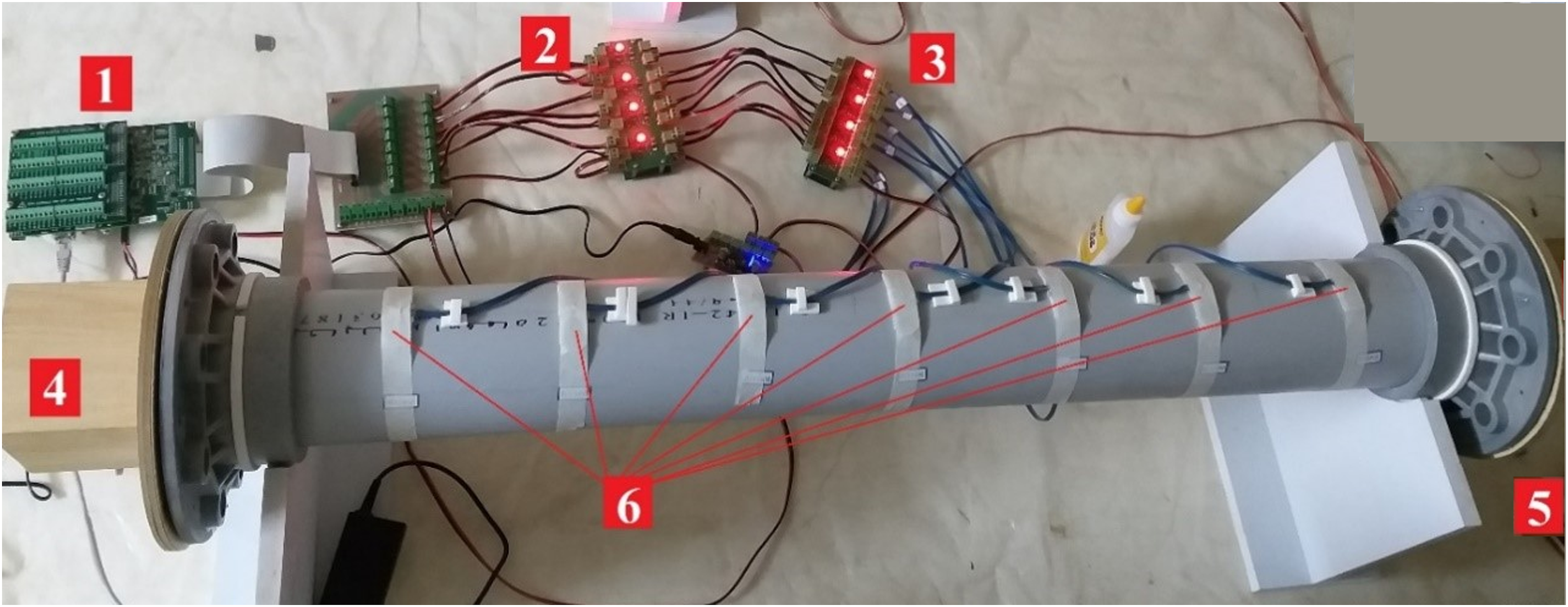
The control algorithm was implemented on an FPGA embedded board called “sbRIO-9626.” Thanks to the high-speed and parallel computation, simultaneous processing of the microphone data with a sampling frequency of higher than 2 kHz is possible. All of the FPGA computations were executed in Fixed-Point status.
3.1. The acoustic modal test
To obtain the natural frequencies and mode shapes of the system, a FEM model is created in COMSOL software; and to validate the results, the acoustic modal test is carried out in two approaches: (1) by sinusoidal and (2) by white noise excitations. In this research, the desired bandwidth of the ANC is in the 450 Hz–750 Hz range. Regarding this fact, only the acoustic modes in this frequency band are considered.
In Figure 3, the FRF amplitude at one of the microphones is compared among three cases of experimental modal analysis with sinusoidal excitation, white noise, and FEM simulation. It is observed that the results of both modal experiments are conformal and modes of 513 Hz and 668 Hz are well recognizable. Although the results of both modal experiments are in good agreement with each other, they have a small difference from the FEM results. This can be due to the simplification assumptions of the system. The loudspeaker was simulated as a vibrating plate, flanges used for attaching the loudspeakers to the pipe were neglected, boundary conditions were considered rigid, and the tapes used for installing the microphones were not modeled. In addition, damping was not considered. Another justification is neglecting the sensor sensitivity in the experimental approach for FRF computation. FRF of the system in the modal test; thin line: sinusoidal excitation, thick line: random excitation, and dashed line: FEM simulation.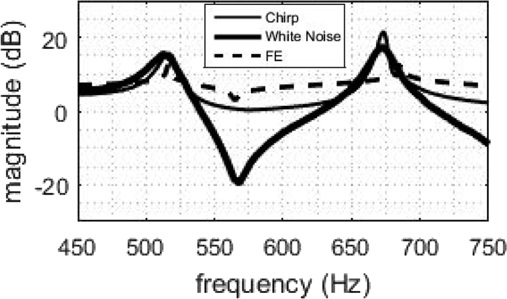
4. Results and discussion
In this investigation, three groups of experiments were conducted. The first group implemented ANC using the NM-FxLMS method to reduce the acoustic potential energy along with the narrowband noise in three various on-resonance and off-resonance frequencies. The second group performed the BM-FxLMS which is proposed in this study. The third group of experiments was carried out to employ the conventional FxLMS algorithm inside the cavity. In all of these experiments, the sampling frequency was 4 kHz, and the number of coefficients for the controller and each FIR filter in the broadband approach was 240 and the step size was
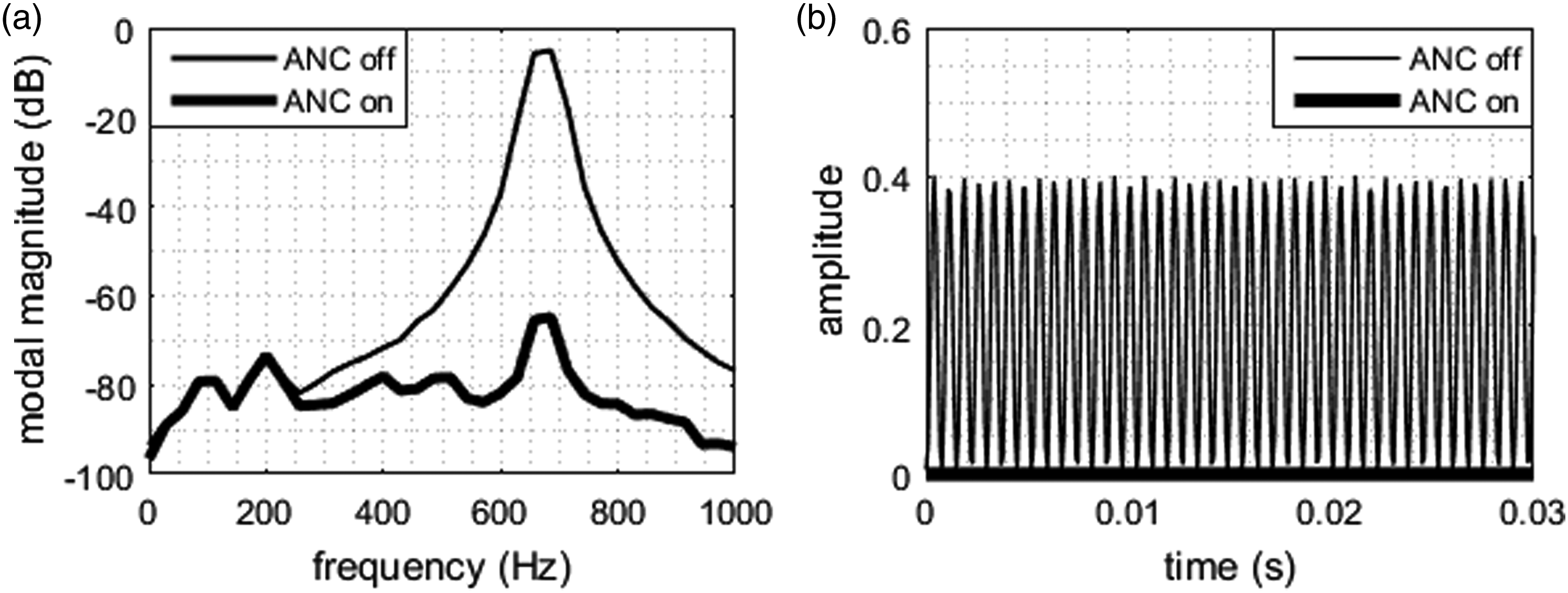
4.1. NM-FxLMS results
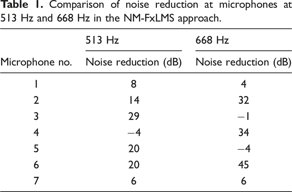
This experiment was carried out in both 513 Hz and 668 Hz on-resonance frequencies. In the first and second experiments, the aim was to reduce the acoustic potential energy along with 513 Hz and 668 Hz sinusoidal noises, and these mode data were used to control the noise. According to Figures 4 and 5, the acoustic potential energy which dominantly stems from 513 Hz and 668 Hz modes has been reduced well. Furthermore, the modal error signal was reduced by about 60 dB in the principal mode. As Table 1 illustrates, the error signal in anti-mode microphones declined significantly, and no reduction occurred for the microphones located on the nodes. Consequently, it is specified that the NM-FxLMS algorithm operates efficiently in both on-resonance and off-resonance frequencies. NM-FxLMS results in 513 Hz frequency: (a) modal error and (b) acoustic potential energy. NM-FxLMS results in 668 Hz frequency: (a) modal error and (b) acoustic potential energy. Comparison of noise reduction at microphones at 513 Hz and 668 Hz in the NM-FxLMS approach.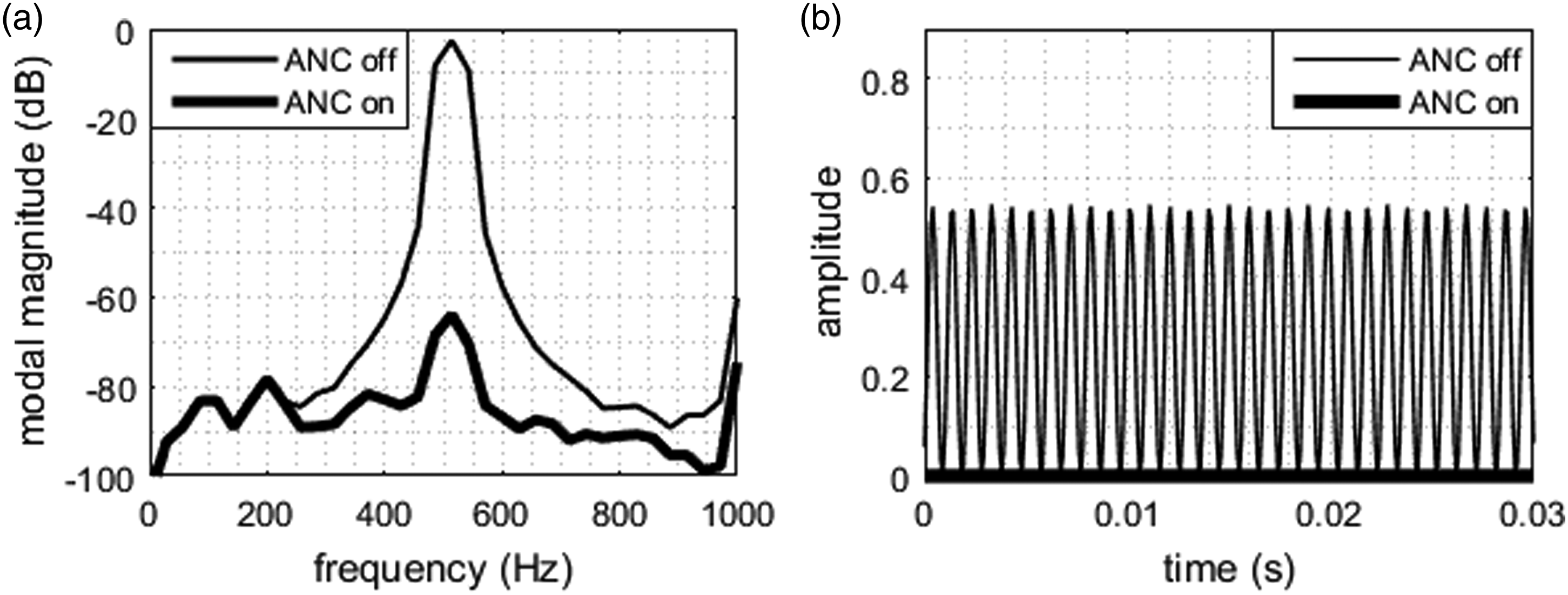
4.2. BM-FxLMS results
In the first experiment, the disturbance was in the range of 450 Hz–550 Hz which is around the 513 Hz mode. The second experiment controlled the 600 Hz–700 Hz band which is located around the 668 Hz mode. In the third experiment, a wider band was considered which includes the 450 Hz–750 Hz band and contains both 513 Hz and 668 Hz acoustic modes.
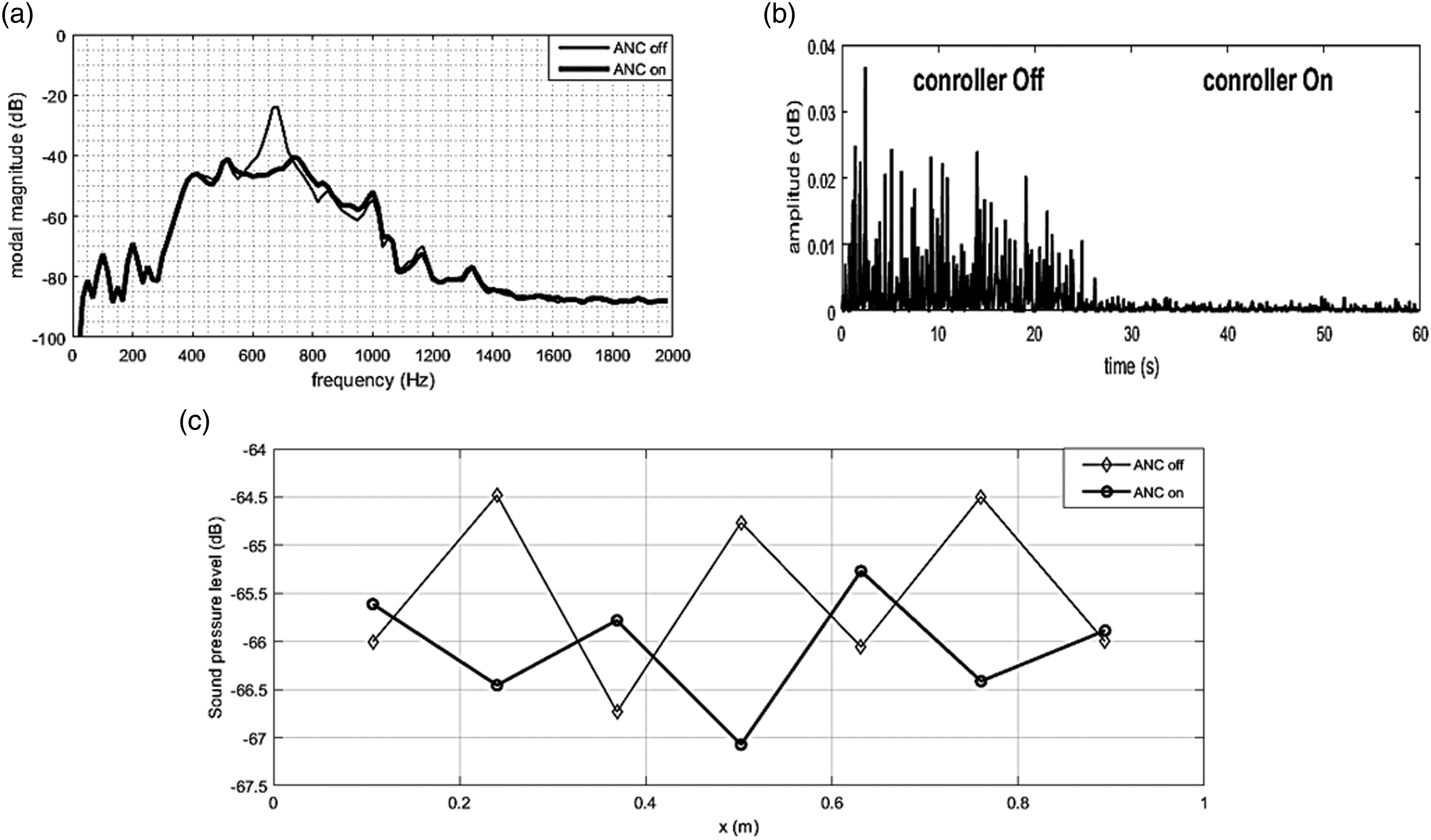
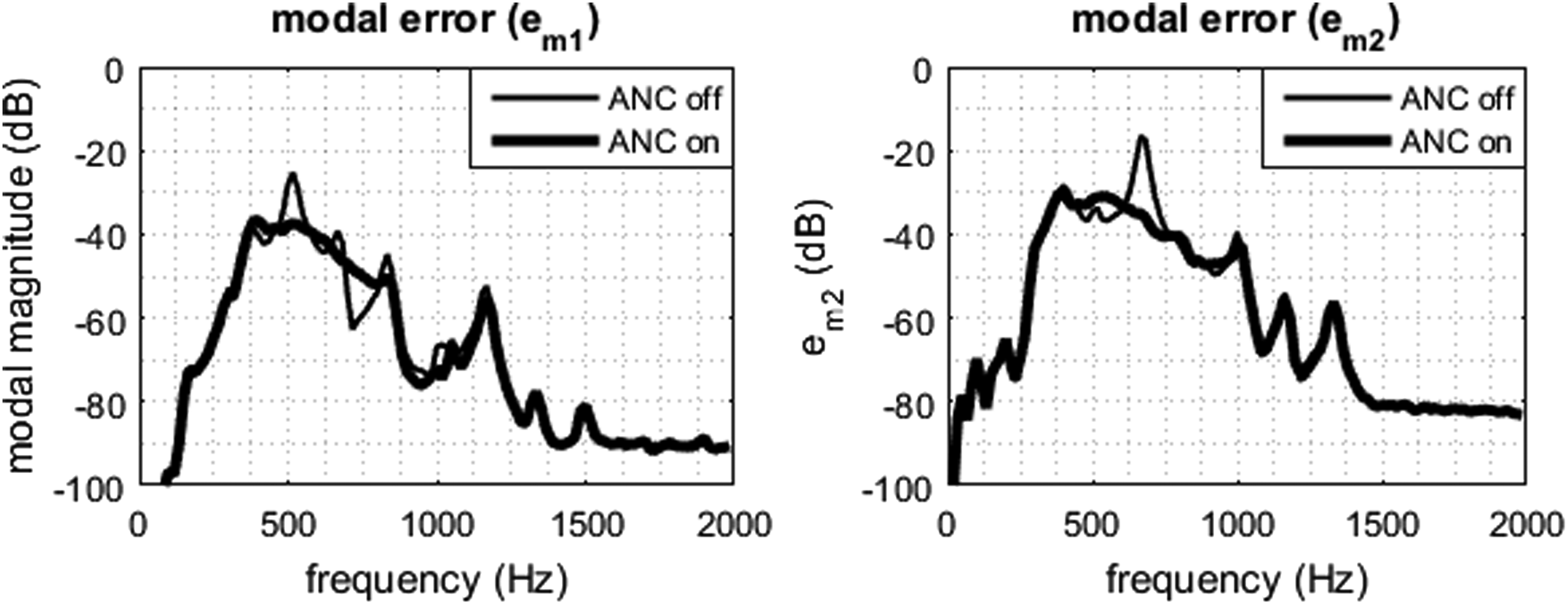
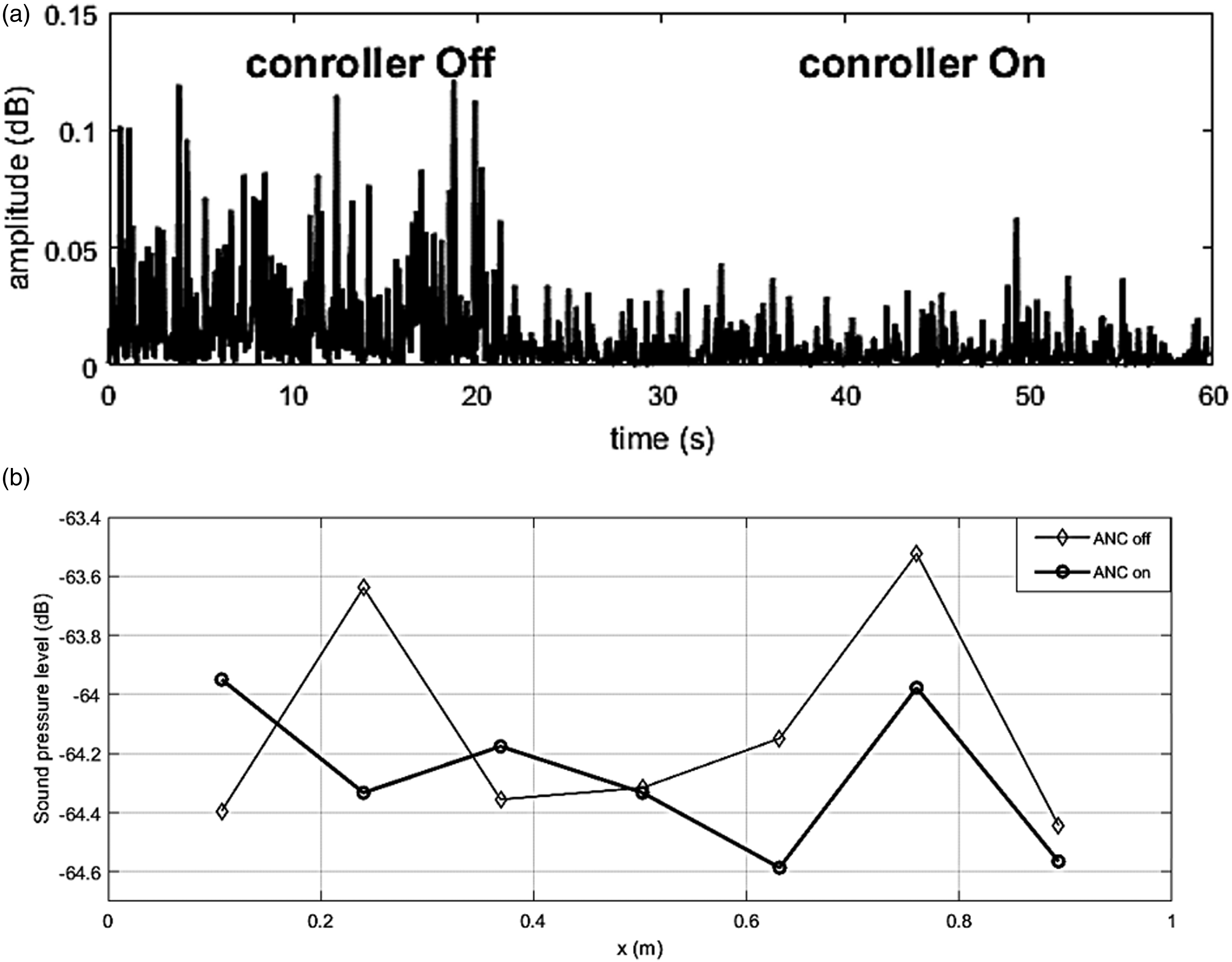
In the first experiment, the acoustic potential energy is often produced by 513 Hz mode; thus, only the modal data of this mode was used to control the noise. According to Figure 6, the modal error signal and acoustic potential energy were suppressed appropriately. The pressure distribution inside the cavity with a 100 Hz bandwidth around this mode is depicted in Figure 6(c). The sound pressure has not been decreased at microphones 1, 4, and 7 since they are located on the modal modes. In the second experiment, only the modal data of the 668 Hz mode was used. The results show that the modal error signal and the acoustic potential energy (Figure 7) were reduced appropriately. The pressure distribution inside the cavity with a 100 Hz bandwidth around this mode is shown in Figure 7(c). Since the microphones 1, 3, 5, and 7 are located on the modal node of this mode, they have not been suppressed. In the third experiment, the aim was to reduce the noise in the 450 Hz–750 Hz band using simultaneous control of both 513 Hz and 668 Hz modes. In this experiment, although the modal error signals (Figure 8) and acoustic potential energy (Figure 9(a)) were diminished suitably, the results are not as good as the other two tests. The pressure distribution inside the cavity with a 100 Hz bandwidth around each mode is plotted in (Figure 9(b)). Since the microphones 2 and 6 are not located on the modal nodes of none of the modes, the sound pressure has been decreased properly at these microphones. To obtain better results, it is recommended to control each mode with an individual loudspeaker. (a) Modal error signal, (b) acoustic potential energy, and (c) pressure distribution inside the cavity in control of 513 Hz mode using BM-FxLMS. (a) Modal error signal, (b) acoustic potential energy, and (c) pressure distribution inside the cavity in control of 668 Hz mode using BM-FxLMS. Modal error signal in simultaneous control of 513 Hz and 668 Hz using BM-FxLMS. (a) Acoustic potential energy and (b) pressure distribution inside the cavity in simultaneous control of 513 Hz and 668 Hz using BM-FxLMS.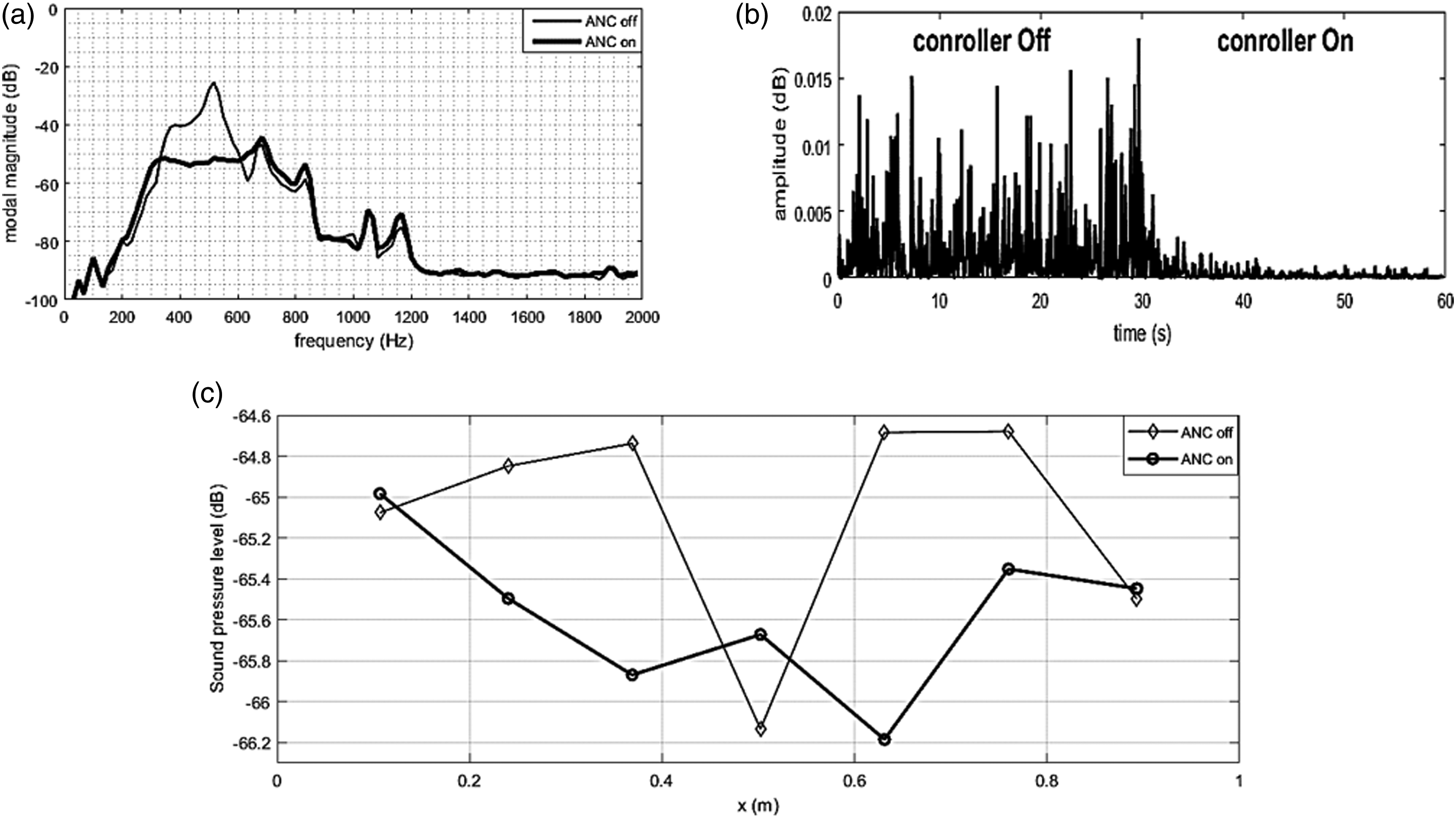
As a general rule, it can be concluded that the error signal is reduced for the microphones located at anti-nodal points of a mode and not reduced or even increased for the microphones located at nodal points of a mode.
4.3. Conventional FxLMS results
This group of experiments included seven tests and the noise was considered in the frequency band of 450 Hz–750 Hz. In the first experiment, microphone 1 was intended to be the error microphone and the second experiment used microphone 2 as the error microphone, and this trend continued to microphone 7 which was considered as the error microphone.
Results illustrate that if the error microphone lies on the anti-node of a mode, it could reduce the noise for any anti-node located microphone. Also, if the error microphone is located on a nodal point, not only the other microphone signal is reduced in that mode, but it might also be increased as well. By the way, using the conventional FxLMS might lead to an increase in the noise inside or outside of the control frequency band. The results of the first experiment are illustrated in Figure 10. Sound pressure level of microphones in conventional FxLMS approach using error microphone 1.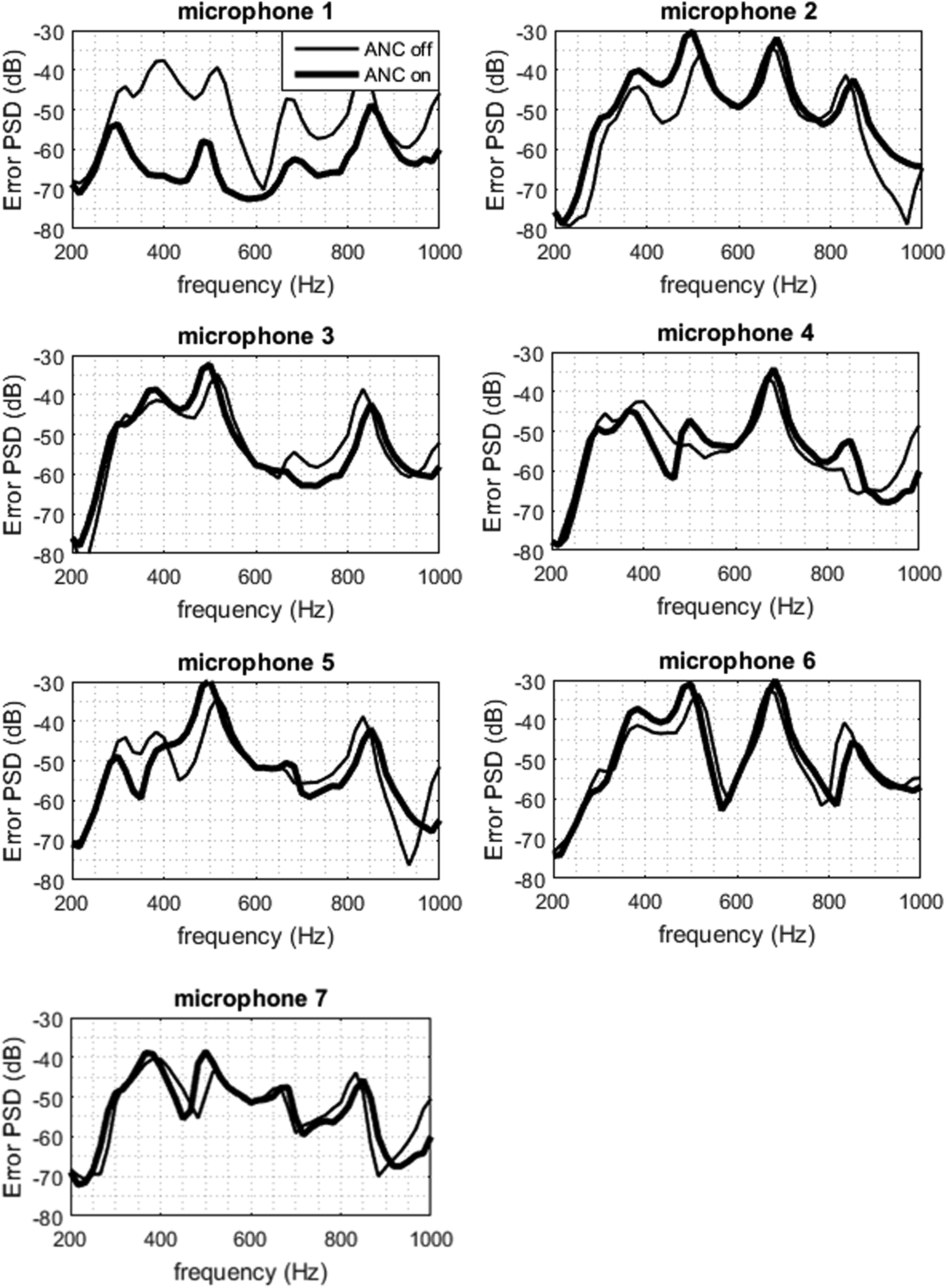
4.4. Comparison of the control signal in conventional FxLMS and BM-FxLMS algorithms
One of the important parameters in the performance comparison of the control algorithms of conventional FxLMS and BM-FxLMS is the cost of control. In this research, the area under the PSD control signal curve in the range of 450 Hz–750 Hz is selected as the cost function (Figure 11). It is observed that in BM-FxLMS experiments along with broadband noise when the aim is to reduce noises around a single mode, a smaller output signal was generated compared to the situation when the noise frequency band contains both modes. This can be due to the small frequency band in one-mode control compared with two-mode control. Moreover, it is observed that although the bandwidth of two-mode control experiments using BM-FxLMS and seven experiments of noise reduction using conventional FxLMS are the same, the former algorithm has reduced noise with less energy consumption. In Figure 11, the cost function of the control signal in all the algorithms is illustrated and can be compared. The cost functions in the BM-FxLMS algorithm approximately are 5–10 dB lower than that of the conventional FxLMS approach. Comparison of the control cost in different control strategies.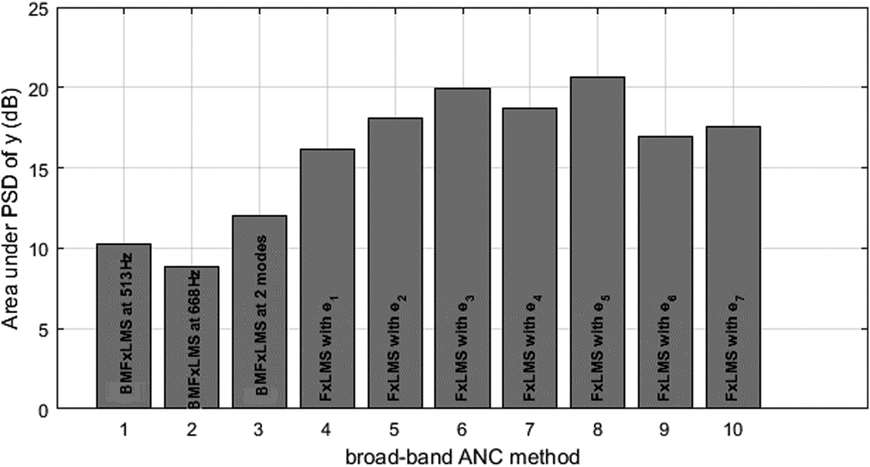
5. Conclusion
This study proposed a broadband active noise control algorithm referred to as broadband Modal FxLMS, to attenuate globally the sound pressure inside a cavity, and demonstrated its effectiveness over conventional FxLMS through experimental tests. The modal parameters including natural frequencies and mode shapes were obtained using the experimental approach (sinusoidal and random excitation) and FEM simulation and were compared with each other. As a result, there was a good agreement among the various approaches in evaluating the mode shapes and natural frequencies. Afterward, global ANC was carried out inside the cavity using the Modal FxLMS algorithm along with narrowband disturbance, and it was observed that the acoustic potential energy was successfully reduced, and also, the global noise inside the cavity was reduced by about 60 dB for on-resonance frequencies and about 10–20 dB for the off-resonance frequencies. Then, the performance of the Modal FxLMS algorithm along with the broadband disturbance was studied and it was observed that this algorithm diminished the acoustic potential energy by about 25 dB. In addition, by analyzing all the error microphones, it was determined that this algorithm has globally reduced noise appropriately. Then, the performance of the conventional FxLMS algorithm in global noise reduction was assessed inside the cavity. It was observed that with the absence of non-linear terms if the error microphone lies on each anti-node of the acoustic mode, it could globally reduce that mode, but not necessarily in the rest of the frequencies in the interval. Additionally, it was determined that the conventional FxLMS algorithm needs a greater control signal which is about 5–10 dB higher than BM-FxLMS.
Footnotes
Acknowledgment
The authors would like to acknowledge the financial support of Entekhab Industrial Group and Isfahan Science and Technology Town for this project under grant numbers PNMSS/9501 and 01-99-01-000135, respectively.
Declaration of conflicting interests
The author(s) declared no potential conflicts of interest with respect to the research, authorship, and/or publication of this article.
Funding
The author(s) disclosed receipt of the following financial support for the research, authorship, and/or publication of this article: This work was supported by the Entekhab Industrial Group (PNMSS/9501), Isfahan Science and Technology Town (01-99-01-000135).