
Abstract
The low/ultra-low-frequency structural vibrations exist widely in some engineering structures, for example, aerospace, naval, and building structures and so on. They could seriously affect the working performance and even cause the destruction of these engineering structures. In order to restrain the low/ultra-low-frequency structural vibration, a locally resonant (LR) metastructure beam equipped with high-static–low-dynamic stiffness (HSLDS) resonators employing negative stiffness magnetic spring is proposed. The analytical model of magnetic negative stiffness spring is firstly derived and the design method of HSLDS resonators is presented based on parametric optimization. Then, the dynamic model of the LR metastructure beam with HSLDS resonators is established using the wave finite element method. The effects of the number of local resonator units on low-frequency band gap are analyzed. Finally, the low-frequency vibration control performance of LR metastructure beam is validated experimentally. The experimental result is in agreement with the theoretical analysis, which demonstrates that the HSLDS resonators are conductive to suppress vibration of the metastructure beam in the low-frequency region (f < 10 Hz). The results also showed that the more the HSLDS resonators are used, the better the vibration suppression effect is.
Keywords
1. Introduction
Vibration could seriously affect the performance and even cause the destruction of the structure. Therefore, it is particularly important to study the vibration suppression approach in engineering field (Fang et al., 2006; Huang, 2009). Over the past few decades, a new type of artificial periodic functional material known as phononic crystals or metamaterial/metastructure is developed, which is characterized by effective properties that are hardly found in natural materials, such as negative density (Milton and Willis, 2007), negative stiffness (Hu et al., 2019; Wang et al., 2019), negative modulus (Fang et al., 2006; Lee et al., 2009), and so on. Furthermore, it has been proved that metamaterial/metastructure features the capability of attenuating waves within some frequency ranges, called stop bands or band gaps. With this distinct feature, metamaterial and metastructure have been widely developed to suppress the vibrations of structure in the past decades.
Two working mechanisms of the band gap in metastructure, namely, Bragg scattering (BS) (Mead, 1996) and local resonance (LR) (Liu et al., 2000), have been confirmed. With respect to Bragg scattering, the band gap is largely dependent on the size of the phononic crystal, which makes it difficult to realize relatively low-frequency vibration control at long wavelengths. By contrast, Liu et al. proposed a phononic crystal structure based on the concept of local resonance, in which the band gap is two times smaller than the order of magnitude lattice constant. Later, the theory of locally resonant has been widely studied and applied on vibration suppression. Casalotti et al. (2018) proposed the concept of metastructure beam endowed with local vibration absorbers to suppress vibrations, which allows a significant reduction of the metastructure beam oscillations associated in the frequency range of 0–4000 Hz. Ma et al. (2018) investigated a metastructure plate equipped with periodic vibration suppressor with multiple secondary oscillators and generated multiple band gaps within the frequency range of 0–1000 Hz. To reduce lower frequency vibrations, a LR metamaterial beam coupled by horizontal springs is proposed by Bao et al. (2021). It is found that vibration suppression performance in the low-frequency region (f < 200 Hz) is enhanced by optimizing the parameters of the metamaterial beam.
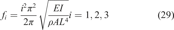
Existing studies have shown that the LR metastructure performed well in vibration suppression and the location of band gaps is the same as the resonant frequency of local resonators (Liu et al., 2000; Hussein et al., 2014). In some engineering fields, for example, aerospace, bridges, automobile, naval, and so on, the suppressions of low/ultra-low-frequency vibrations in structures are usually in demand in order to avoid effect of vibration, which may affect performance of the structure and even damage the structure. Thus, in order to realize low/ultra-low-frequency band gaps of metastructure, local resonators with low/ultra-low resonant frequency should be designed. However, there are few researches on low/ultra-low-frequency vibration suppression among various configurations of metastructure. According to the vibration theory, for the passive linear vibration reduction system with mass m and stiffness k, the resonant frequency is
In recent years, researchers have introduced the conception of negative stiffness to solve the contradiction between the bearing capacity and the low-frequency vibration isolation (Alabuzhev and Rivin, 1989), and thus, the resultant isolation system has low/ultra-low resonant frequency, which is termed as the characteristic of high-static–low-dynamic stiffness (HSLDS). Zhou et al. (2017) proposed a local resonator with HSLDS and shifted the band gap of flexural wave in a metastructure beam to a lower frequency range by using negative stiffness mechanism. Wu et al. (2019) designed a low-frequency multi-mode (LFMM) resonator based on two-stage HSLDS resonators to suppress multiple low-frequency modal vibrations of a structure. In the above work, the negative stiffness mechanisms are realized by mechanical springs, that is the elastic element of the resonator constructed by combining a vertical spring with two oblique springs, which can provide negative stiffness in the vertical direction, and thus, the stiffness of the vertical spring can be effectively counteracted (Carrella et al., 2007; Cao et al., 2006). However, this kind of negative stiffness mechanism has the disadvantages of low space utilization and the problem of friction. Recently, magnetic springs are introduced to negative stiffness mechanism to realize vibration isolation (Carrella et al., 2007). Zheng et al. (2016, 2018) utilized the magnetic mechanism to design quasi-zero stiffness isolator in both horizontal direction and torsional direction according to different requirements, which provides a basis for the application of magnetic spring in vibration suppression of LR metastructure. Wang et al. (2020) put forward a semi-active metamaterial beam for frequency band gap turning ranged from 50 to 300 Hz. However, studies on local resonator with negative stiffness magnetic spring (NSMS) for low/ultra-low-frequency vibration reduction of metastructure have not reported so far.
In summary, a metastructure beam with HSLDS resonators is proposed to suppress the structural low-frequency vibration in the paper. The wave finite element method (WFEM) is employed to establish the mathematical model of metastructure beam with HSLDS resonators and calculate its band gaps. In addition, parametric optimization of the metastructure beam with HSLDS resonators is discussed to provide the guide for the design of metastructure. Furthermore, an experimental study is carried out to validate the low-frequency vibration suppression performance of metastructure beam with HSLDS resonators.
The paper is organized as follows: in section 2, the conceptual design and theoretical model of a metastructure beam with HSLDS resonators are addressed. In section 3, the numerical analysis of HSLDS resonator is performed to explore the optimized parameter of springs and the method of designing metastructure beam is discussed. In section 4, parametric effect study on propagation characteristics is performed for optimal design of a metastructure beam. In section 5, an experimental setup is proposed to validate the vibration suppression effect of LR metastructure beam.
2. Modeling of metastructure beam equipped with HSLDS resonators
2.1. Configuration of LR metastructure beam and HSLDS resonators
Considering an elastic beam with spatial periodic distribution and periodically attached local resonators through threaded connection, as sketched in Figure 1(a). (a) Model of LR metastructure beam and (b) the section view of the resonator.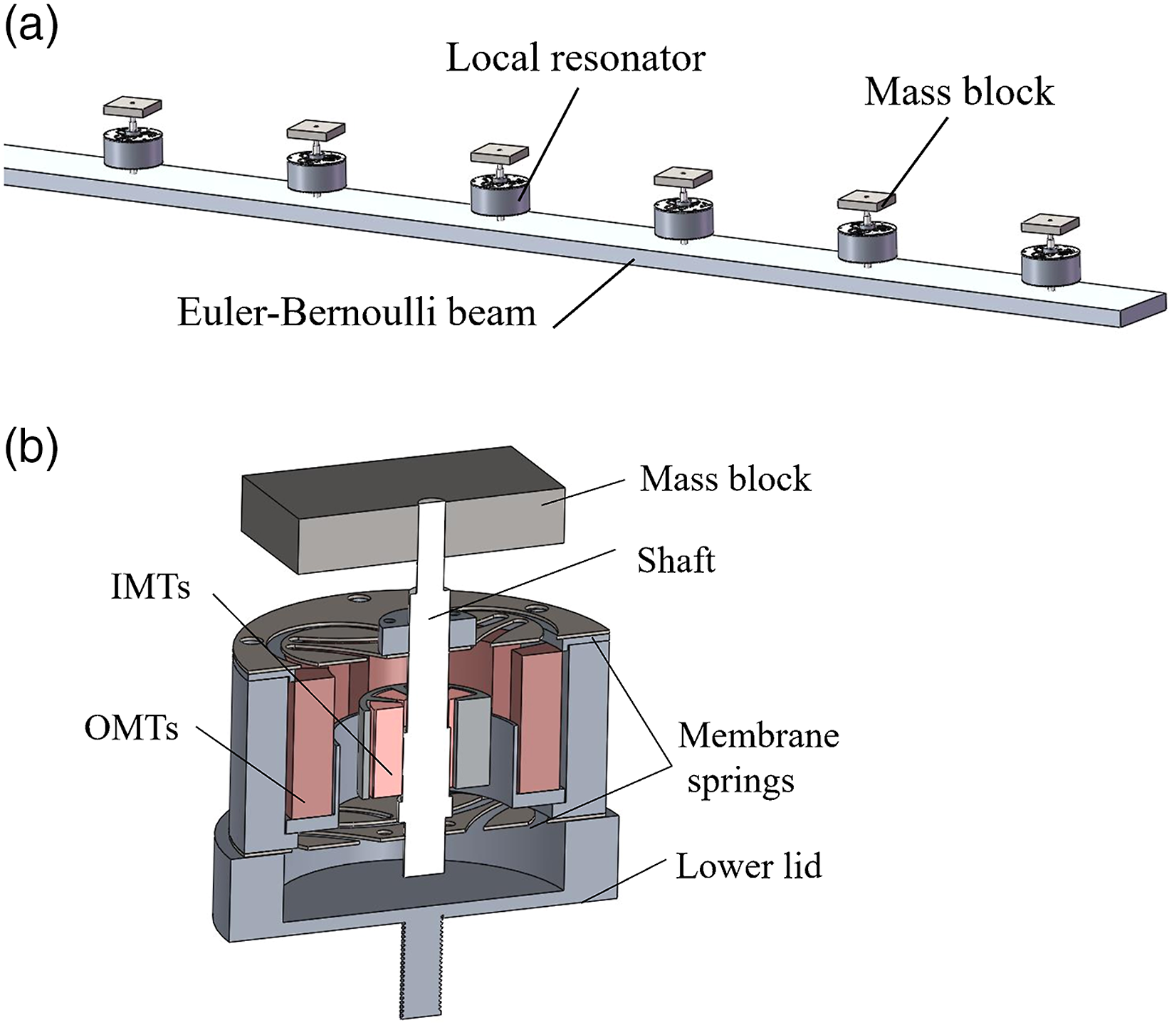
Figure 1(b) shows the configuration of HSLDS resonators. As mentioned above, low-frequency band gaps correspond to low resonant frequency of local resonators, and then, a local HSLDS resonator aimed at generating low/ultra-low resonant frequency with enough bearing capacity is addressed in detail. As is shown in Figure 2(a), two membrane springs are designed to support the static load of the mass block, which possesses positive stiffness and constrains the shaft to move along the axial direction. The structure of the NSMS is presented as Figure 2(b). The inner magnetic tiles (IMTs) and outer magnetic tiles (OMTs) are magnetized uniformly along the radial direction and installed in a repulsive configuration. Hence, this configuration is unstable in the axial direction and can produce negative stiffness to cancel the positive stiffness of the membrane springs, whereas it is stable in the radial direction. It should be noted that the centers of IMTs and OMTs are coincident when the mass is fully supported by the membrane spring. Near the equilibrium position, the low dynamic stiffness of each resonator can be realized due to counteraction between the negative stiffness of the magnetic springs and the positive stiffness of the membrane springs. With this configuration, it can be anticipated that the resonator possesses low/ultra-low-frequency modes by designing the physical parameters of each spring. (a) Model of membrane spring and (b) equiaxial side view of NSMS (the blue arrows indicate the direction of magnetization).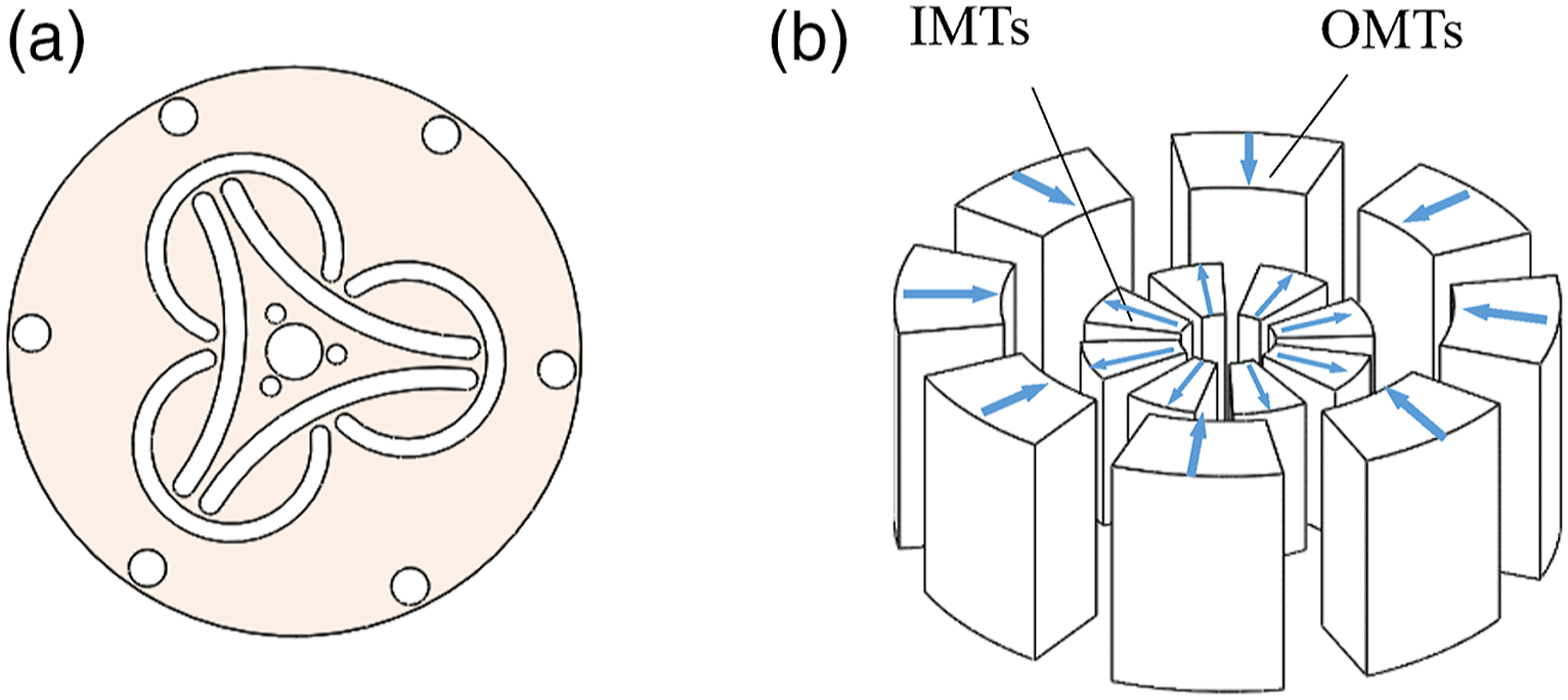
2.2. Modeling of HSLDS resonator
To calculate the magnetic negative stiffness of resonator, longitudinal view and a pair of IMT and OMT of NSMS is demonstrated in Figure 3. As shown in Figure 3(a), the radial thicknesses of IMTs and OMTs are T1 and T2, respectively, and their heights are 2L1 and 2L2, respectively. The inner radius of IMTs is R1 and the inner radius of OMTs is R2. As shown in Figure 3(b), for a magnet tile magnetized uniformly, the charge density on the faces is Schematic of NSMS: (a) Longitudinal section view (to show geometric parameters) and (b) schematic of magnetic force calculation between internal and external magnetic tiles.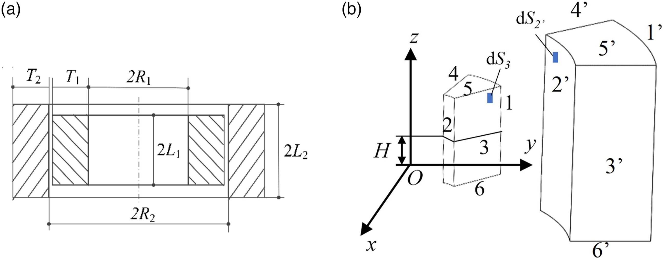
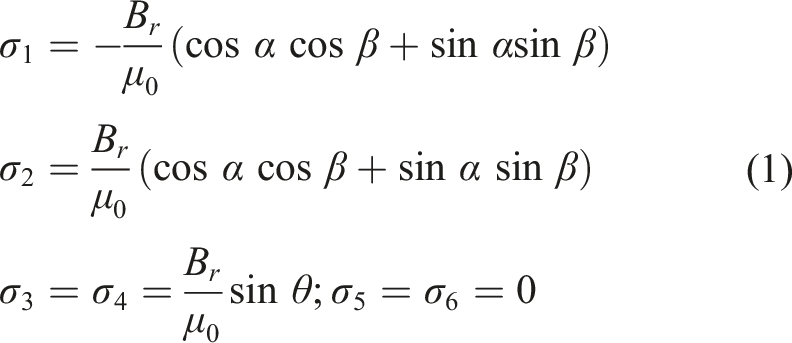
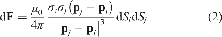
The magnetic force between charge on face element dS
i
and that on face element dS
j
is
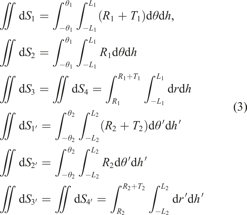
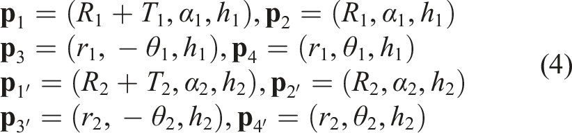
The columnar coordinates of position vectors
Similarly, the other 8-term moduli of the position vectors between the face element on the surfaces 2′ and 4′ and the element on the inner magnetic tile surfaces 1, 2, 3, and 4 can be obtained. The component of d
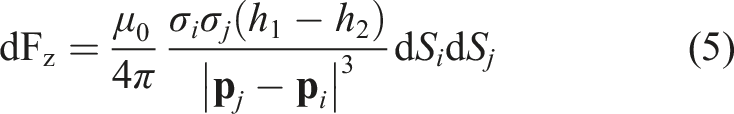
The magnetic stiffness related to
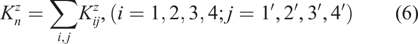
Both the inner ring magnet and the outer ring magnet are composed of 8 magnet tiles. An arbitrary magnet tile from the inner ring magnet and an arbitrary magnet tile from the outer ring magnet are taken to form a magnet tile pair (64 pairs in all), the magnetic force and stiffness of which can be calculated using equation (6). Then, the total magnetic stiffness produced by the NSMS can be calculated by summing the 64 terms. Thus, the total stiffness of the resonator is

2.3. Modeling of LR metastructure beam using WFEM
The WFEM (Mace et al., 2005; Nobrega et al., 2016; Zhou, 2014), which starts from a conventional finite element method, is used to establish the dynamic model of LR metastructure beam and calculate its band gaps. Figure 4(a) shows the simplified model of LR metastructure beam, which is divided into n unit cells. Figure 4(b) shows a unit cell of length Δl, which contains one HSLDS resonator and one segment of basic beam. The HSLDS resonator is simplified as the spring with stiffness k
R
and the mass of the resonator components (including magnetic spring and membrane spring) is simplified as the equivalent concentrated mass m0. The mass of the mass block is m
R
. Simplified model of LR metastructure beam: (a) 2D model of the LR metastructure beam and (b) one unit cell of the LR metastructure beam.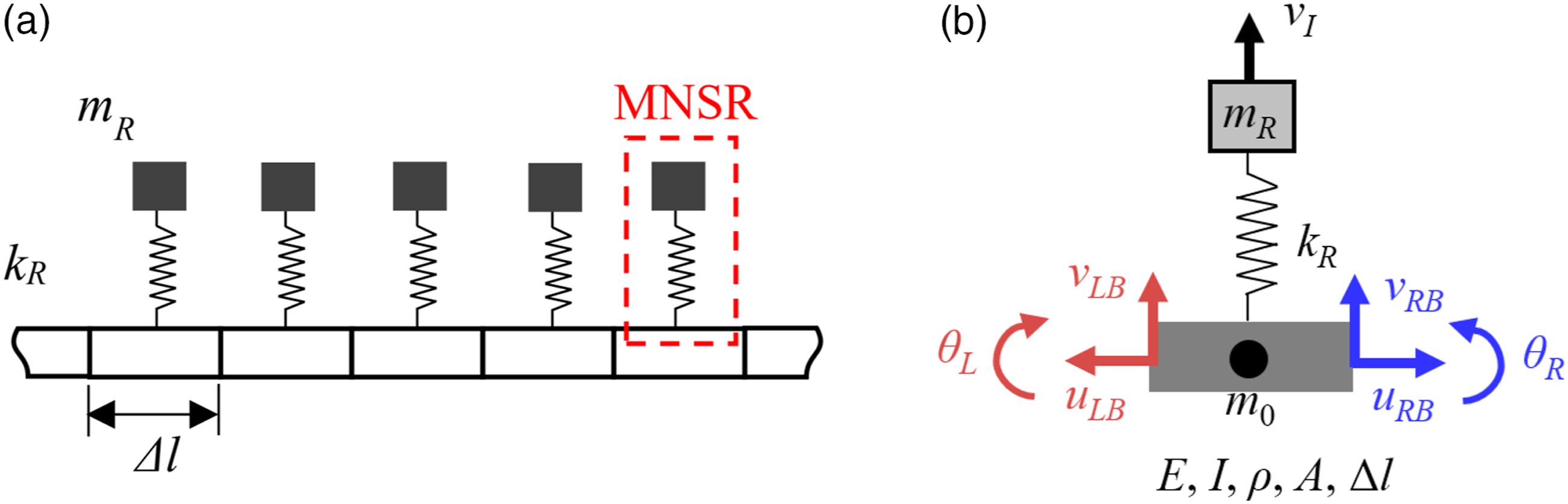
For a periodic unit cell as shown in Figure 4(b), the equilibrium equation of the resonator attached at a unit cell point can be written as


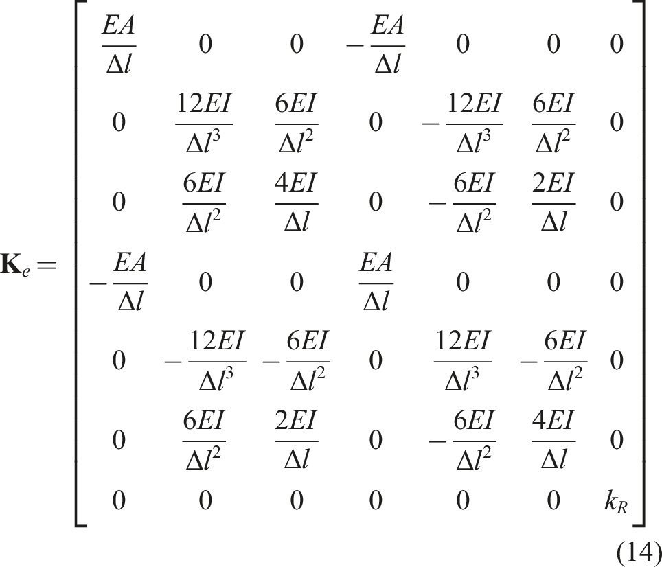
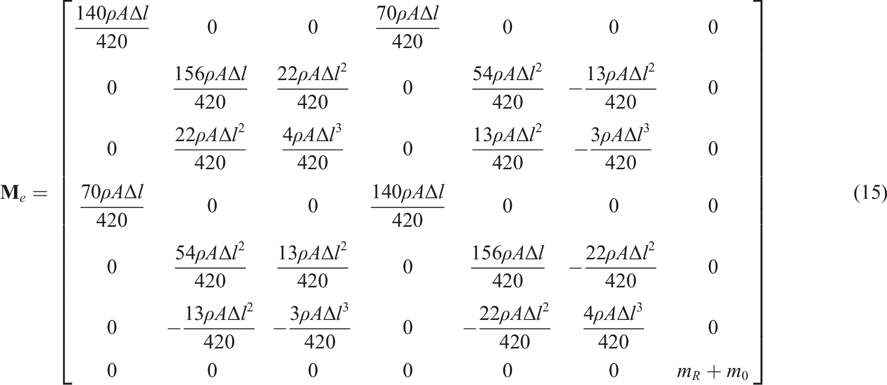
The mass and stiffness matrices
The matrix
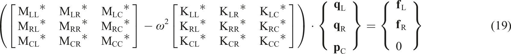
where superscript “*” represents the reduced model and

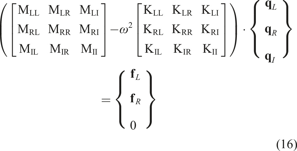
Equation (8) can be expressed in matrix form as
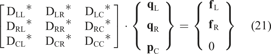
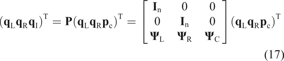
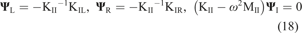
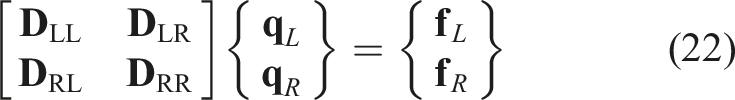
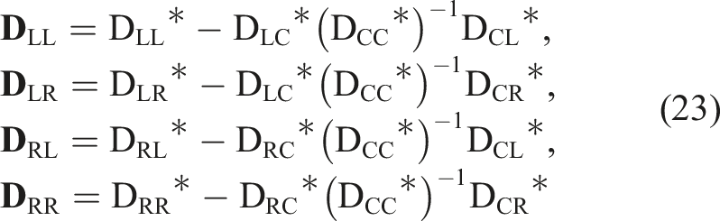
According to the third line of equation (21), the internal degrees of freedom can be eliminated through dynamic condensation; thus, equation (21) can be written as
For periodic metastructure beam, due to the continuity between two unit cells, the relationship of displacement continuity and force balance between the right interface of the n-th cell and the left interface of the (n+1)-th cell is satisfied, namely,

Under the passage of a wave of the form
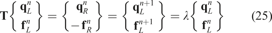
The eigenproblem is posed in terms of the transfer matrix
In these equations, the propagation constant λ describes the amplitude and phase change over a distance Δl and is expressed by

3. Design methodology of HSLDS resonator
3.1. Determination of negative stiffness of magnetic spring
According to equation (7), the total stiffness of the resonator, k R , is the sum of the negative stiffness of the magnetic spring, k n , and the positive stiffness of the membrane spring, k p . To realize low/ultra-low resonance frequency, the magnetic negative stiffness plays the key role. The negative stiffness k n can be simulated by equation (6), which is related to the residual magnetic flux density of magnets (B r ), the gap (equals to R2 +T2 −R1−T1), the height difference (L2−L1), and the thickness (T1 and T2) of OMTs and IMTs.
Figure 5 shows the effects of B
r
on the stiffness characteristic. The displacement H is the relative distance between the center of magnets height. As is shown in Figure 5, only B
r
varies while the other parameters remain unchanged. The negative stiffness appears at the equilibrium position and the interval with constant stiffness can be regarded as the effective working range of magnets. As B
r
increases, the value of negative stiffness at the equilibrium position increases notably while the working range of magnets narrows slightly, so a trade-off between the value of negative stiffness and effective working range should be made when designing B
r
of the magnets. Effect of B
r
of the magnets on the stiffness characteristic, R1 = 1.8 mm, T1 = 2.2 mm, L1 = 3.2 mm, R2 = 7 mm, T2 = 3 mm, and L2 = 5 mm. Effect of the gap between OMTs and IMTs on the stiffness characteristic, B
r
= 1.4 T, R1 = 1.8 mm, T1 = 2.2 mm, L1 = 3.2 mm, T2 = 3 mm, and L2 = 5 mm.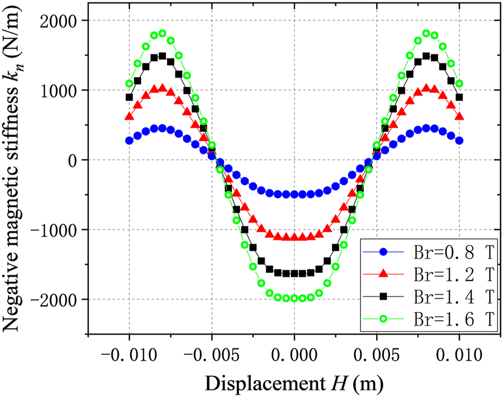
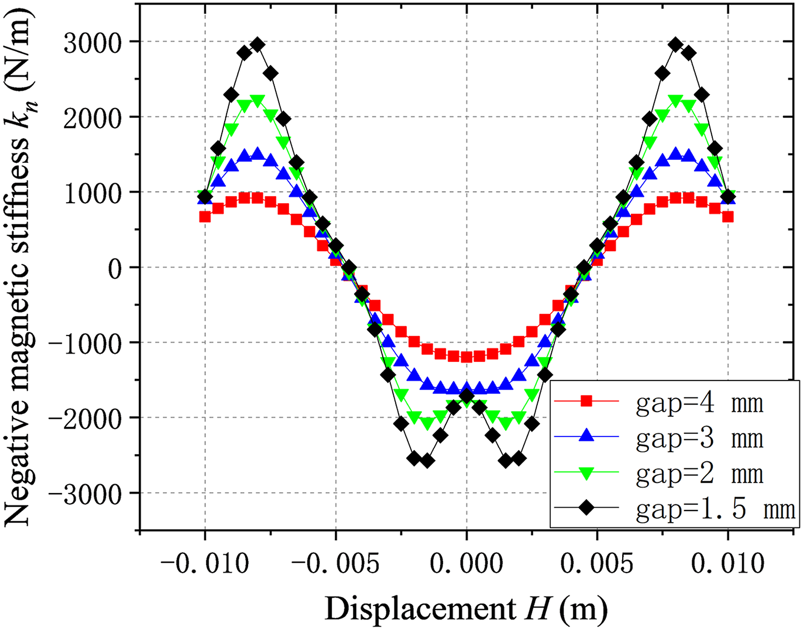
From Figure 6, it can be seen that increasing the gap between OMTs and IMTs makes the negative stiffness near the equilibrium position more uniform. However, the penalty is that the negative stiffness produced by the NSMS is totally reduced. It is also notable that as the value of gap increases, the stiffness shape near the equilibrium position changes from a convex one to a concave one, which means that magnetic spring will change from a softening system to a hardening system accordingly. Therefore, increasing gap provides an effective means to reduce the nonlinearity of stiffness and increase working range.
The effect of height difference between OMTs and IMTs (L2−L1) is shown in Figure 7. It can be seen from the blue and black dot plots that when the height difference is zero, the value of k
n
is large near the equilibrium position, but the working range becomes tiny nonetheless. Therefore, the height of OMTs and IMTs cannot be the same. When the absolute heights of OMTs and IMTs are same, it seemed to have no effect on the value of k
n
, and the key factor determining k
n
is the height difference between OMTs and IMTs. The value of k
n
decreases with larger height difference, but the effective working range broadens. Effect of the height difference between OMTs and IMTs on the stiffness characteristic, B
r
= 1.4 T, R1 = 1.8 mm, T1 = 2.2 mm, R2 = 7 mm, and T2 = 3 mm.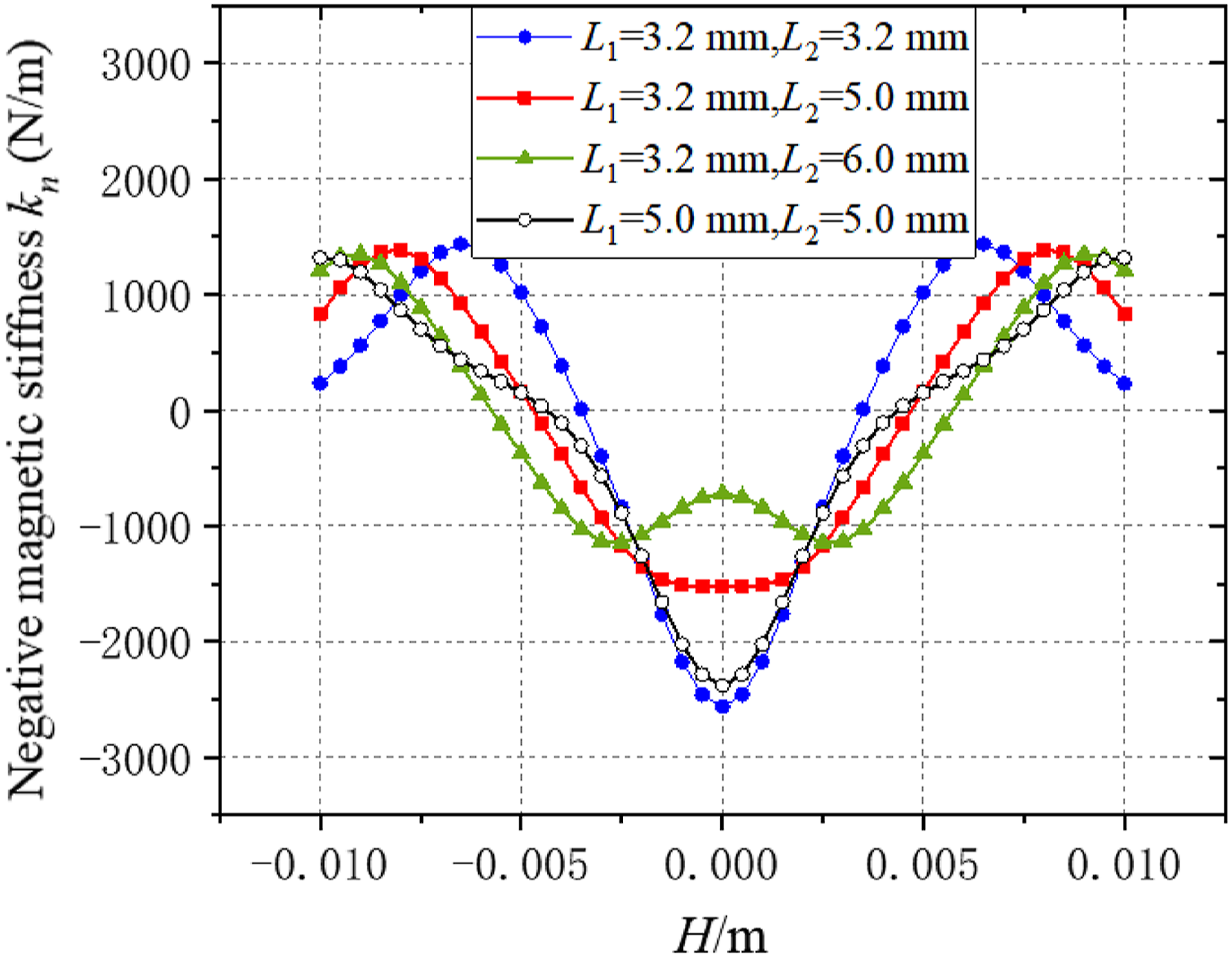
The last parameter, thickness (T1 and T2) of OMTs and IMTs, is performed in Figure 8. When the other parameters remain unchanged, increasing the radial thickness of magnetic tiles will enhance the negative stiffness and almost has no effect on the working range. Effect of the thickness of OMTs and IMTs on the stiffness characteristic, B
r
= 1.4 T, R1 = 1.8 mm, L1 = 3.2 mm, and L2 = 5 mm.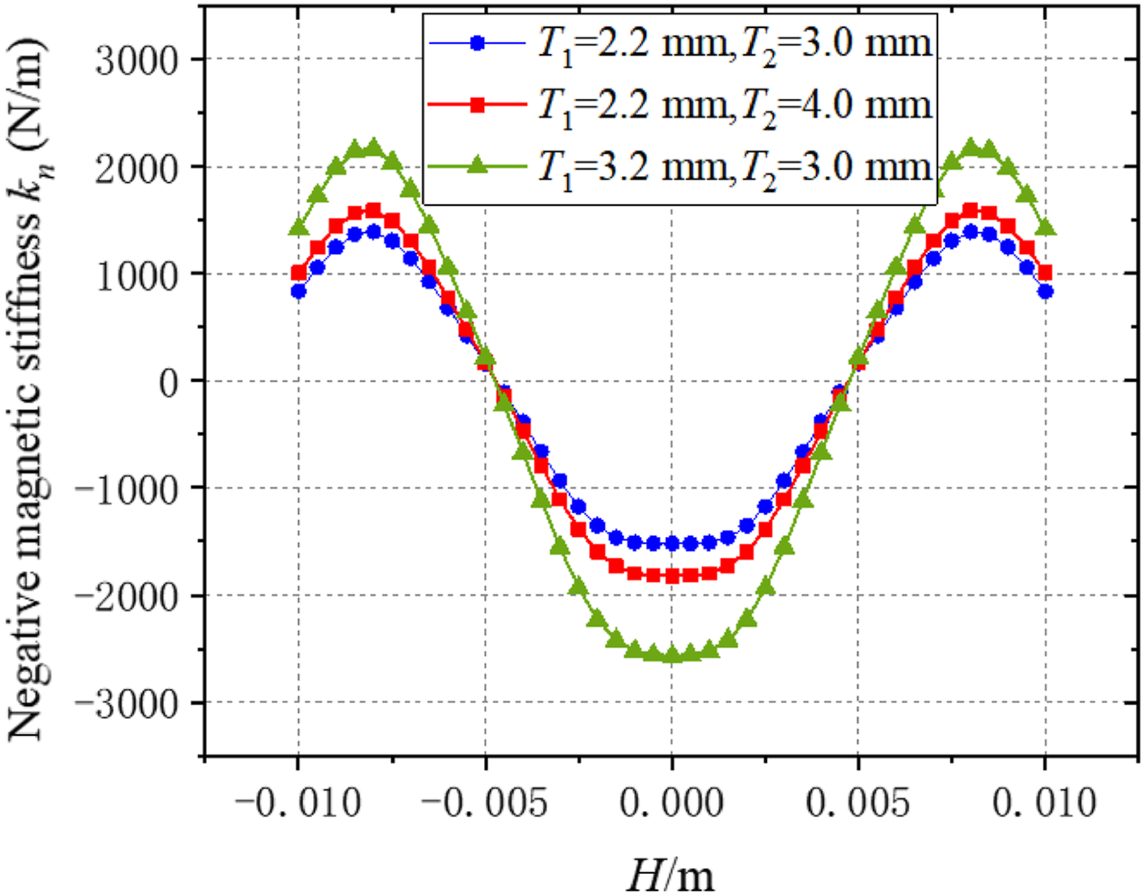
From the discussions above, it can be summarized that the main idea of designing magnetic tiles is to get larger value of k n and wider working range. Firstly, B r should be set as about 1.4 T. Then, an appropriate height difference between OMTs and IMTs is set, and the working range is broadened by increasing the gap. At the same time, the negative stiffness value is increased by increasing the thickness of OMTs and IMTs as much as possible.
3.2. Determination of positive stiffness of membrane spring
The geometric shape of the membrane spring is shown in Figure 2 (b). The axial deformation of the membrane spring is very small when the vibration amplitude is slight; thus, its stiffness can be regarded as a constant. The positive stiffness k p provided by membrane spring can be obtained using finite element analysis software, for it’s hard to calculate numerically. Therefore, the value of k p can be determined first when designing the resonator, and then, the parameters of OMTs and IMTs can be adjusted so that k p and k n constitute a lower total stiffness of resonator to provide a lower resonant frequency.
4. Simulated studies on vibration suppression performance of LR metastructure beam with HSLDS resonators
4.1. Design of LR metastructure beam
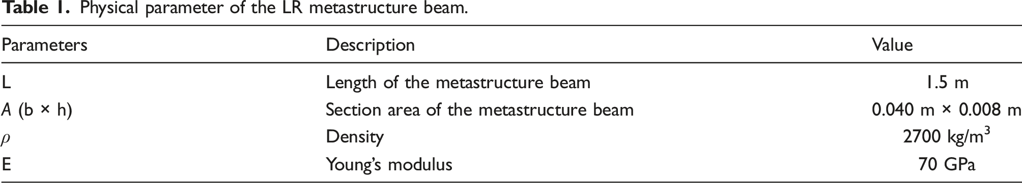
Physical parameter of the LR metastructure beam.
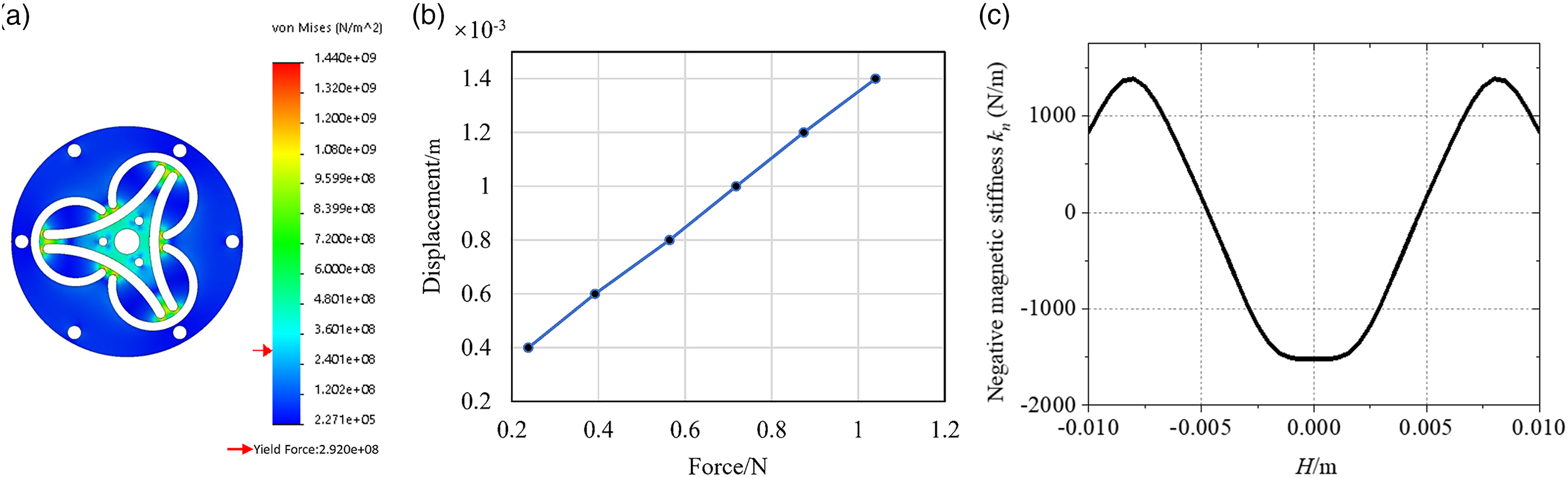
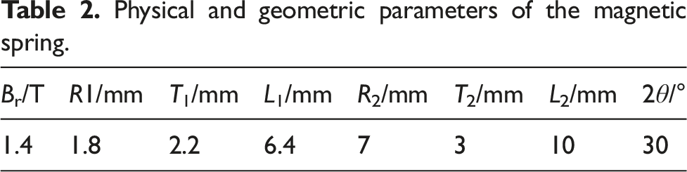
The membrane spring configuration as shown in Figure 2(a) is adopted, with a diameter of 27 mm and a thickness of 0.25 mm. The corresponding positive stiffness k
p
provided by the membrane spring can be simulated as is shown in Figure 9(a) and (b), which is 770 N/m calculated by finite element analysis. The parameters and corresponding negative magnetic stiffness of the designed magnetic spring are shown in Table 2 and Figure 9(b). From equation (7), the total stiffness of resonator is (a) Finite element analysis of membrane spring, (b) restoring force versus deformation curve of the membrane spring, and (c) negative stiffness of magnetic spring. Physical and geometric parameters of the magnetic spring.
The mass of the mass block matched on the shaft of the resonator is 0.016 kg, and the natural frequency of the resonator is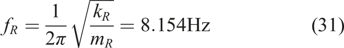
The natural frequency of the designed resonator is consistent with the first-order natural frequency of the metastructure beam. The rationality of the design of the LR metastructure beam is discussed in the next chapter.
Figure 10 shows the dispersion characteristic curves of a sample LR metastructure beam in the form of propagation constant λ and wavenumber k. When |λ|< 1 or Imag(k) < 0, the propagation of the wave is suppressed, and the corresponding frequency range (the shaded part) is the band gap. The value at the band gap represents the attenuation amplitude of the propagated wave. For the convenience of description, wavenumber k is used to describe the dispersion characteristics of waves. Low-frequency band gap characteristics of LR metastructure beam: (a) Curve of frequency f and propagation constant λ and (b) curve of frequency f and wavenumber k.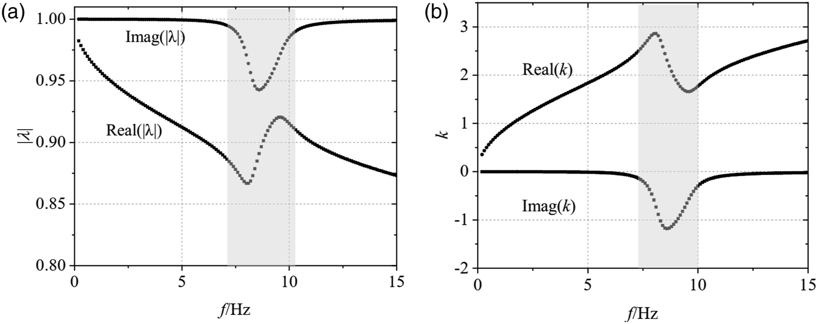
4.2. Effects of HSLDS resonator number on vibration suppression performance
The wave equation of the unit cell shown in Figure 4(b) is given by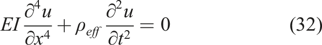

Substituting equation (33) into equation (32) to obtain
Thus, the eigenequation is
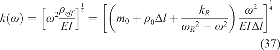
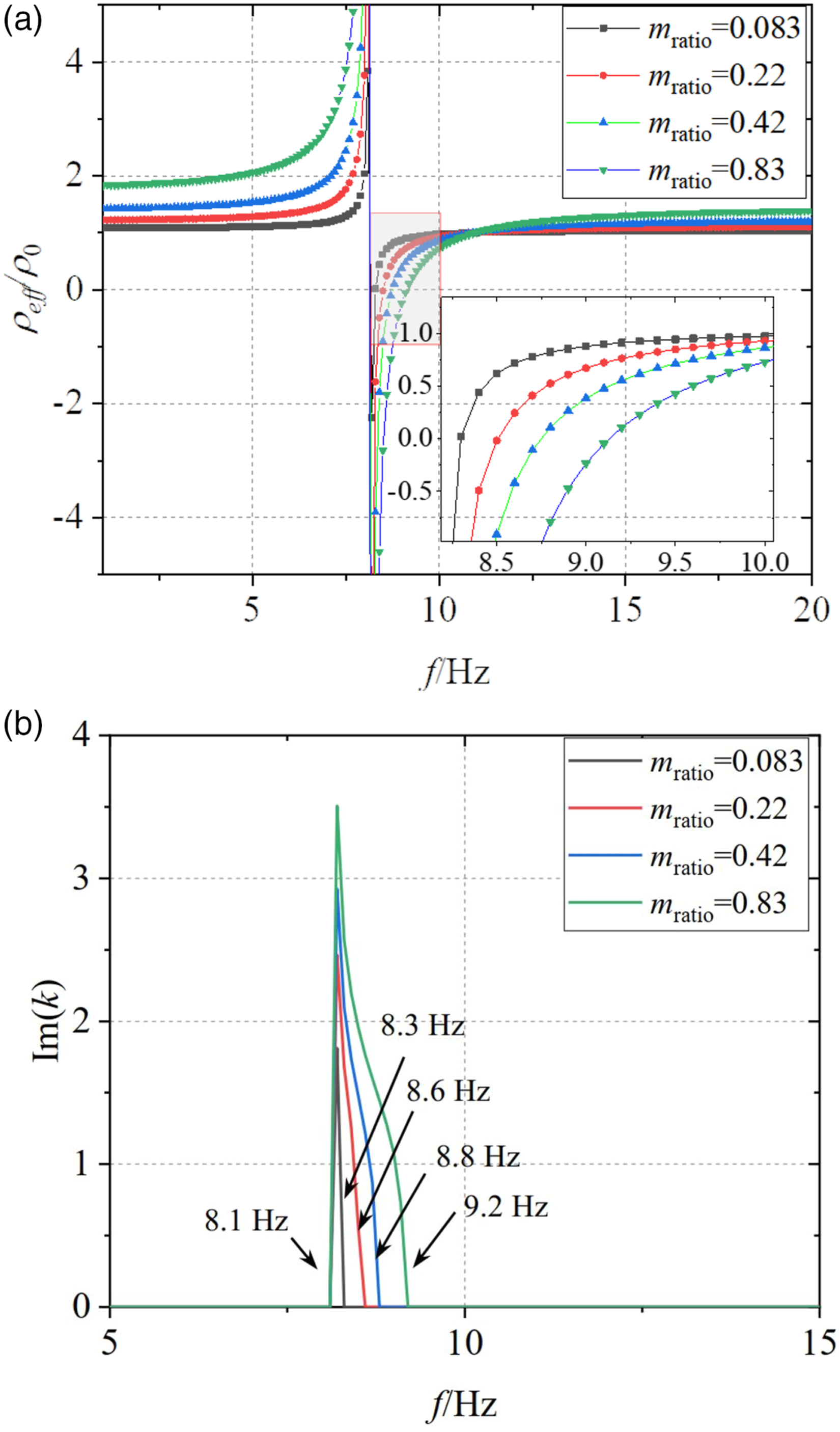
The effective density ρ
eff
is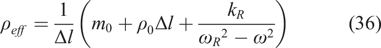
The mass ratio of resonator and unit cell is (a) Effective density of unit cell and (b) imaginary part of wavenumber.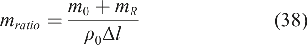
The above analysis is aimed at the unit cell. Analysis for the LR metastructure beam is performed to illustrate the relationship between the number of resonators and band gap as shown in Figure 12. The number of resonators n is identical with m
ratio
in Figure 11. From curves in Figure 12, we can see that the band gap characteristic of LR metastructure beam corresponds to that of unit cells. When the number of resonators increases from 2 to 29, the initial frequency of the band gap decreases and the termination frequency increases, that is, the overall width of the band gap broadens. As a result, the effect of vibration reduction of the metastructure beam is improved obviously. (a) Dispersion characteristics of the LR metastructure beam under different number of resonators and (b) start and stop frequencies of bang gap.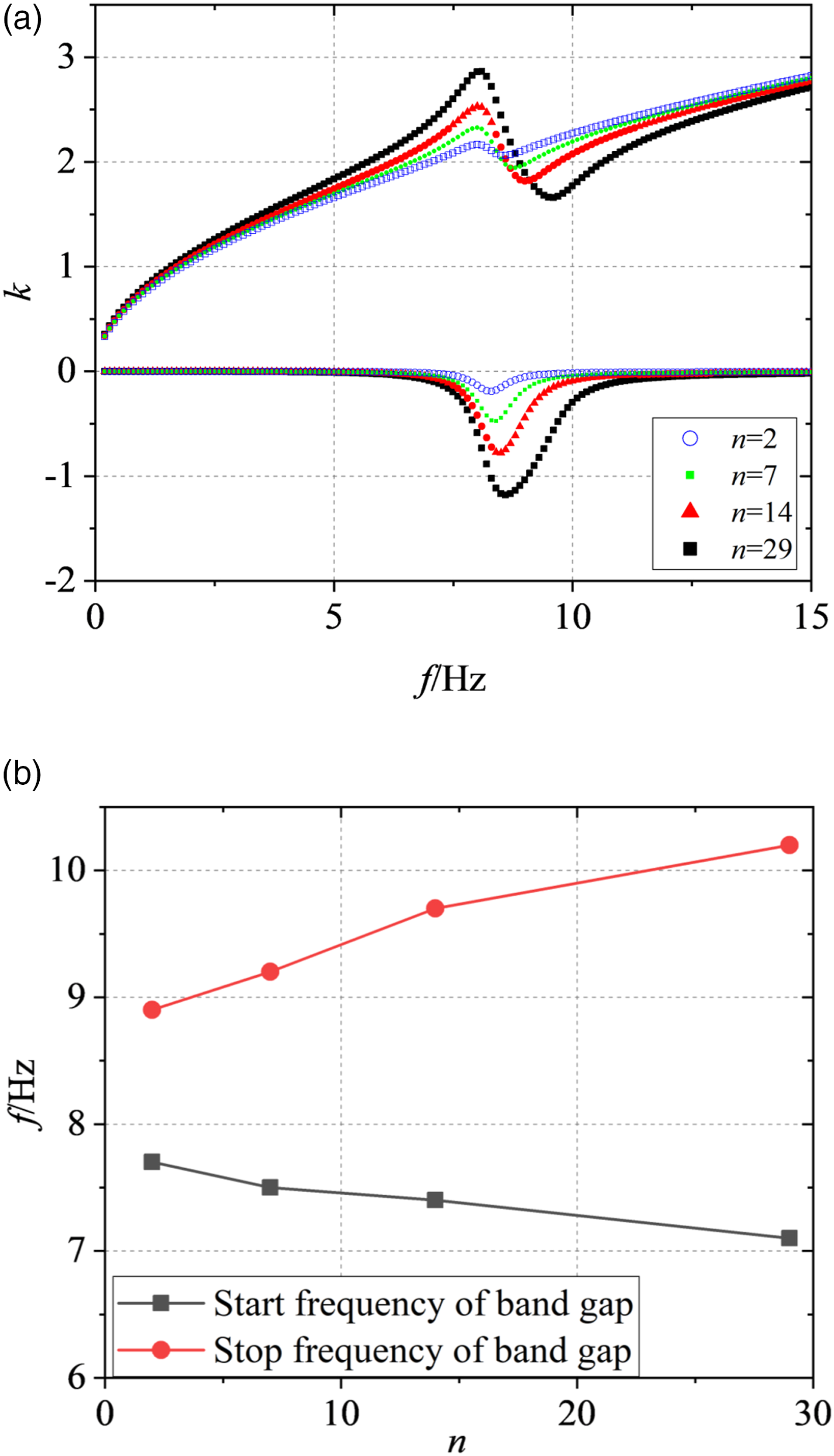
5. Experimental verification
5.1. Performance test of HSLDS resonator
The experimental test on a fabricated HSLDS resonator is firstly performed. The block diagram of the experiment and the photograph of the resonator is shown in Figure 13(a), where the parameters of magnetic springs is given in Table 2. The magnet material is NdFeb, which has strong magnetism. The material of membrane spring and mass block is stainless steel, and the other parts (shaft, lower lid, etc.) are made of aluminum alloy. The mass of the mass block is 0.016 kg. The resonator is excited by a B&K 4808 shaking table. One accelerometer is placed on the mass block and another is placed on the shaking table. A B&K PULSE system is used to control the shaking table and collect and process data from the accelerometers. A sine sweep signal with a frequency range of 1–100 Hz is exerted by the analyzer and then fed into the shaking table. The transmissibility from the base to the mass is measured by two accelerometers, namely (a) The schematic diagram of the experimental setup and the photograph of the fabricated HSLDS resonator and (b) the tested transmissibility of the resonator in different cases.
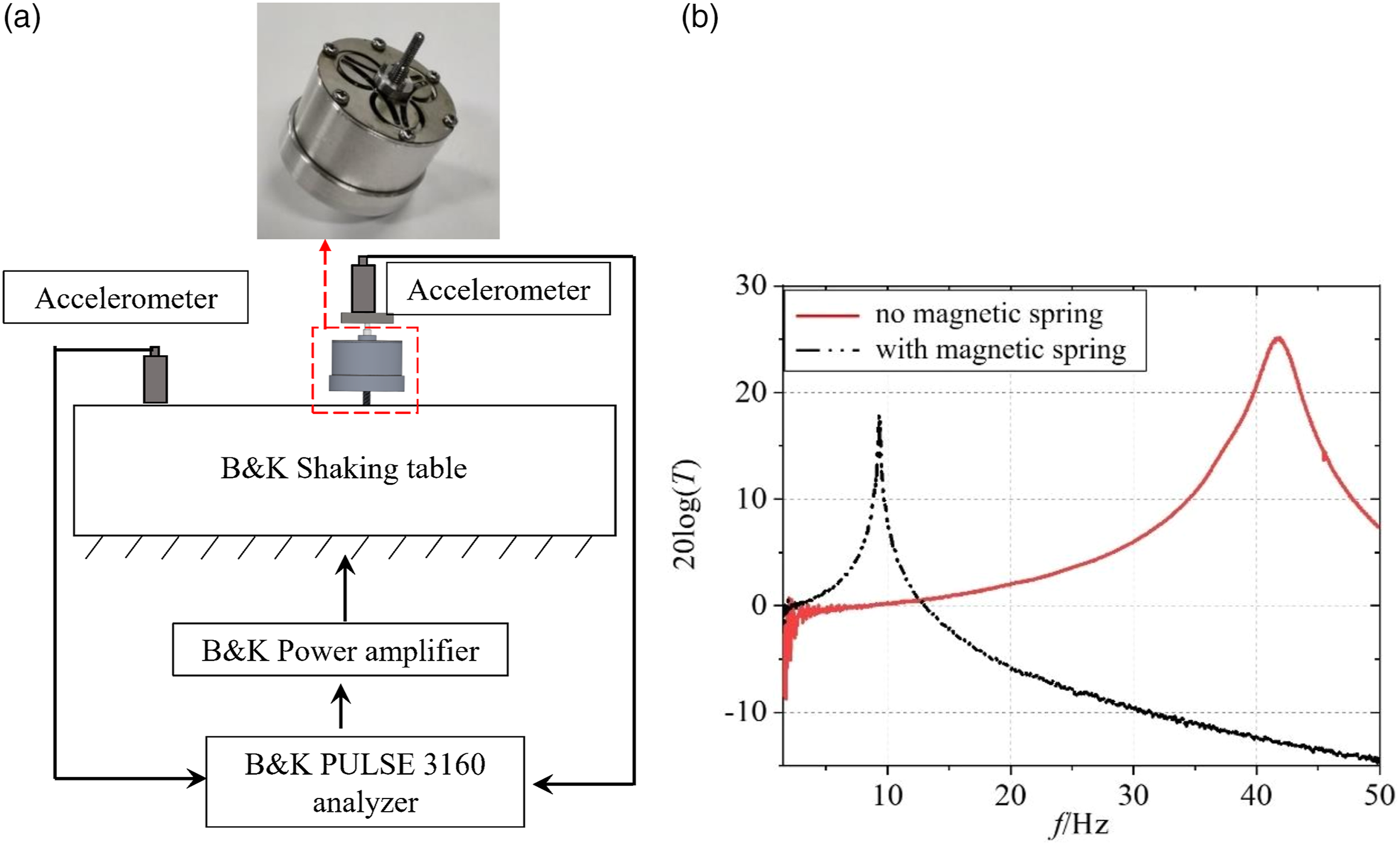
The experimental results are shown in Figure 13(b). It can be seen that the resonance frequency of the resonator with no magnetic spring is 41.8 Hz. By adding a magnetic spring, the resonance frequency of HSLDS resonator becomes 9.2 Hz. The corresponding dynamic stiffness decreases from 1103.7 N/m to 53.4 N/m and the reduction ratio is 95.1%. Therefore, the negative stiffness of the magnetic spring and the positive stiffness of the membrane springs obtained through the test at the equilibrium position are
These are consistent with the theoretical values.
5.2. Vibration suppression experiment of LR metastructure beam
Figure 14 shows the schematic diagram of LR metastructure beam test and the photograph of the test platform. The HSLDS resonators are periodically arranged on the base beam, and the beam is simply supported through the clamping mechanism at both ends. Different from the test of HSLDS resonator, the vibration signal is transmitted to the beam by the excitation rod. One end of the excitation rod is connected with the B&K shaking table, and the other end is connected with the impedance head, which is placed on the lower side of the metastructure beam to collect the input signal. The accelerometer is placed on the upper right side of the metastructure beam to measure the output signal. The signal collected by the acceleration sensor is sent to the B&K PULSE 3160 analyzer. Test platform of LR metastructure beam: (a) schematic diagram and (b) photograph of the experimental setup of LR metastructure beam.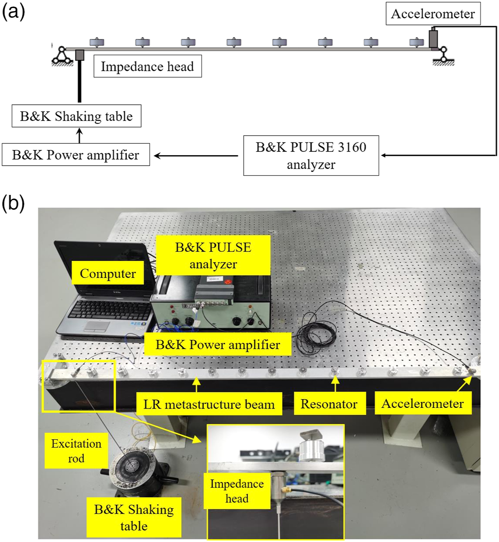
The characteristics of the base beam are verified firstly. A sweep sine signal is applied on the left end of the beam through the B&K PULSE system. The acceleration response of the beam measured by the acceleration sensor at the right end is shown in Figure 15(a). The first three natural frequencies of the basic beam are f1 = 8.62 Hz, f2 = 34.25 Hz, and f3 = 77.37 Hz, respectively, which are basically consistent with the theoretical resonant frequencies. Next, different numbers of resonators are installed on the basic beam to measure the frequency response function (FRF) of the metastructure beam, as shown in Figure 15(b). As can be seen from the diagram, due to the influence of added mass, the first-order natural frequency of metastructure beam decreases slightly. More importantly, with the increase of number of resonators, there is an obvious attenuation at the first-order natural frequency where the corresponding band gap is produced. In addition, the width of band gap is closely relative to the number of resonators, which is in line with the theoretical analysis above and verifies the feasibility of the design method. (a) Acceleration response of the basic beam and (b) FRF of the metastructure beam with different number of resonators.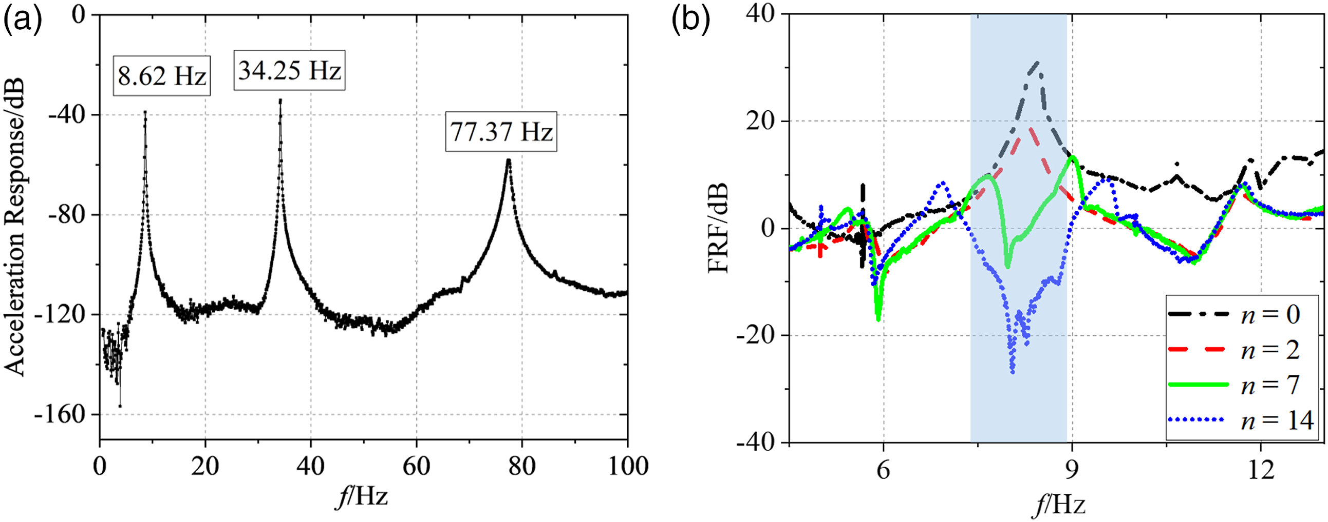
6. Conclusions
This study proposed a LR metastructure beam coupled with HSLDS resonators. The static characteristics of both magnetic spring and membrane spring were analyzed by the numerical method and finite element method. The way to design the NSMS with larger negative stiffness and wider working range is provided. The dynamic model of the LR metastructure beam is established by the WFEM and the way to design the LR metastructure beam is summarized. The effects of the number of the local resonators on the band gap and vibration suppression performance have been analyzed. The results demonstrate that with the increase of the number of local resonators, the metastructure beam can effectively suppress the vibration in the low-frequency region (f < 10 Hz) and form an obvious band gap. At the same time, it was verified by experiment that the HSLDS resonators possess lower dynamic stiffness and resonant frequency. In addition, the larger number of resonators is more advantageous to the vibration suppression of the beam. The work provides a way for possible applications where the low/ultra-low-frequency vibrations of structure need to be suppressed.
Footnotes
Declaration of conflicting interests
The author(s) declared no potential conflicts of interest with respect to the research, authorship, and/or publication of this article.
Funding
The authors disclosed receipt of the following financial support for the research, authorship, and/or publication of this article: This work was supported by the National Natural Science Foundations of China (Grant No. 11872290), NSAF (Grant No. U1430129), and National Natural Science Foundations of China (Grant No. 12072247).