
Abstract
Based on the traditional active noise control method, a phased-array secondary sound source was designed to replace the traditional sound source. Adopting a 4 × 4 array distributed design, we still maintain a single-in single-out system. Simulations show that the phased-array secondary sound source better controls noise reduction in a certain area of space, with better noise reduction effect, larger static area, and less impact on other non-control areas. A verification experiment was performed in a semi-anechoic chamber, with noise reduction conducted in different directions. The noise reduction effect of the phased-array secondary sound source was >10 dB higher than that of the traditional secondary sound source, with less influence on other points. The phased-array secondary sound source can be combined with tracking equipment to achieve a better follow-up noise reduction effect in space.
1. Introduction
When reducing noise with active noise control (ANC) in three-dimensional space, the secondary sound sources used in traditional way are mostly non-directional sound sources. The noise reduction mainly relies on local mutual interference effects. The noise reduction area is usually small, the noise reduction may cause noise increase in irrelevant area (Aslan and Paurobally, 2018; Brooks et al., 2005; Elliott, 2014; Olson & May, 1953; Xu and Sommerfeldt, 2014). When the control direction is no longer on the axis of the secondary sound source, the noise reduction effect deteriorates with the increase of the angle between the control direction and the axis (Furuhashi et al., 2018; Zhen et al., 2013; Iwai et al., 2018; Zhang and Li, 2019). Therefore, in applications that require active noise tracking control (ANTC), such as head tracking noise reduction and ANC headrests, the traditional way is not useful because of the unmatched angle. Deploying secondary sound sources and sensors in multiple locations can better address this problem (Baek and Elliott, 1995), and most current ANC headrests use similar schemes (Elliott et al., 2018; Han et al., 2019). Elliott and Nelson introduced the general technique of multipole analysis (Elliott and Nelson, 1993); however, the resulting ANC system has changed from a simple SISO system (single input single output) to a MIMO system (multiple input multiple output), which increases the computational cost and system complexity (Ntumy and Utyuzhnikov, 2014). The number and location of secondary sound sources and sensors largely determine the control effect (Zhang and Qiu, 2014). Although the range of noise control areas with MIMO has increased, their locations are still fixed. The system cannot track a specific noise control area and cannot meet the requirements of varying environments (Chi et al., 2019). Binding the noise reduction area with the secondary source can ensure a relatively good control effect when the two move together (Liao et al., 2011). However, the practicality of this method is very limited.
To address the above problems, this study used a directional phased sound array (DPSA) as the secondary source to perform ANC for a local area in three-dimensional space. The system was SISO. It changes the spatial directivity of the array source by altering its components’ phases, instead of using the mechanical motion of the secondary source. In addition, it can perform stable and efficient noise control on different local areas in space, and it can also flexibly combine with a tracking system for ANTC. To study the influence of the single sound source and the DPSA source on the spatial sound field, the finite element method was used to analyze the sound field before and after noise control. Experiments were designed and implemented to verify the superiority of the secondary sound source of the speaker array in spatial ANC.
2. ANC based on phased-array
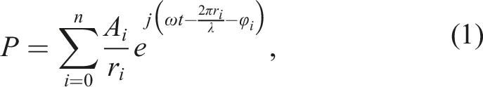
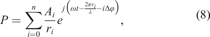
This study compares simulation and experimental results to study the characteristics of the spatial sound field under control. The experiment draws on the FxLMS (filtered-x least mean square) algorithm to construct a feedforward ANC system, because it is simple to implement and the computational cost is small (Cheer et al., 2017; Siswanto et al., 2015). For phased-array, changing the initial phase of each element in the array to form a stepping phase can deflect the directivity of the array (Wan et al., 2014). Without changing the position of the secondary source, the phase control method can be used to adjust the array beam direction to achieve ANC in space (Hu et al., 2019). The sound pressure at a certain point in the space with multiple sound sources of the same frequency in the space is Directivity deflection of the phased-array.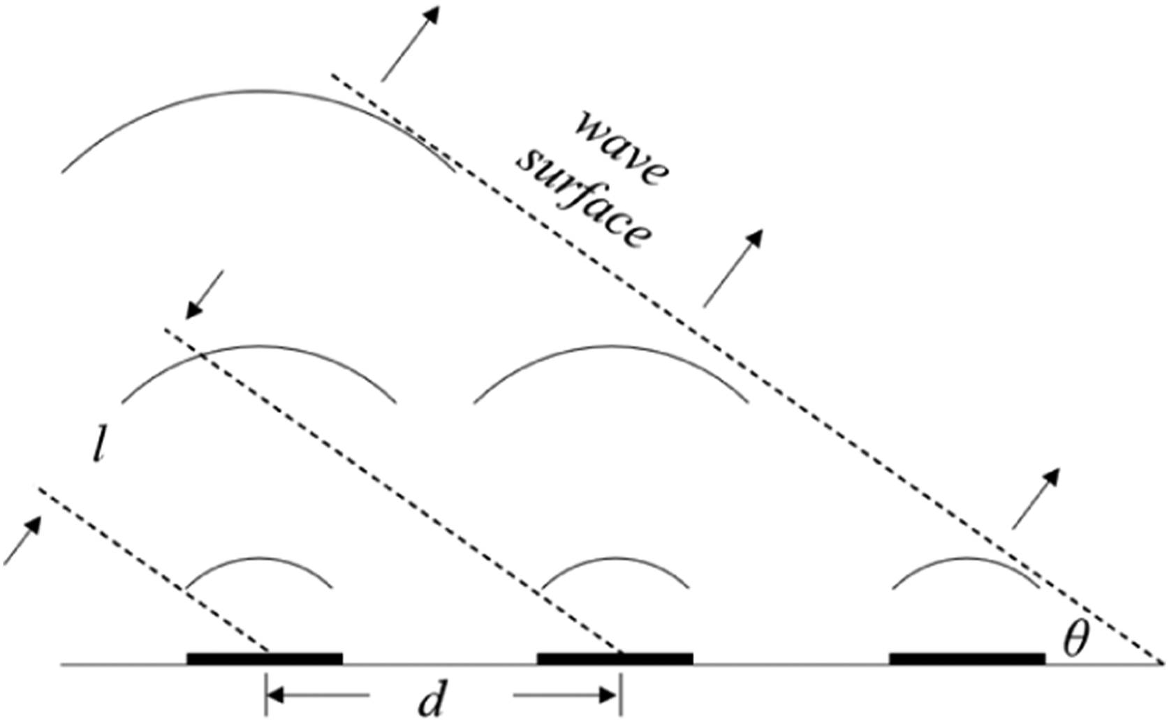

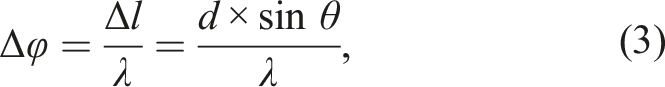
The phase difference Δφ of adjacent elements is
The time delay Δt between each two adjacent array elements is

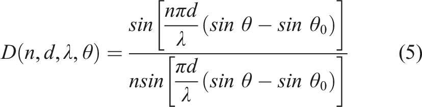
In this notation, the directivity of the secondary source of the array is given by
By copying the linear loudspeaker array in parallel and extending it to the plane, the plane loudspeaker array can be obtained. The product theorem is still applicable to the directivity expression of planar rectangular sound source array (Li et al., 2010). Therefore, the directivity of planar rectangular sound source array, whose number of array elements is M × N, can be given by
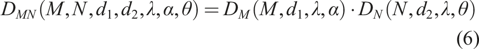
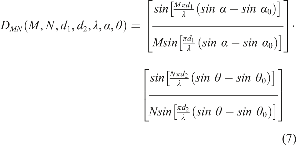
where Beam directional deflection of plane sound source array.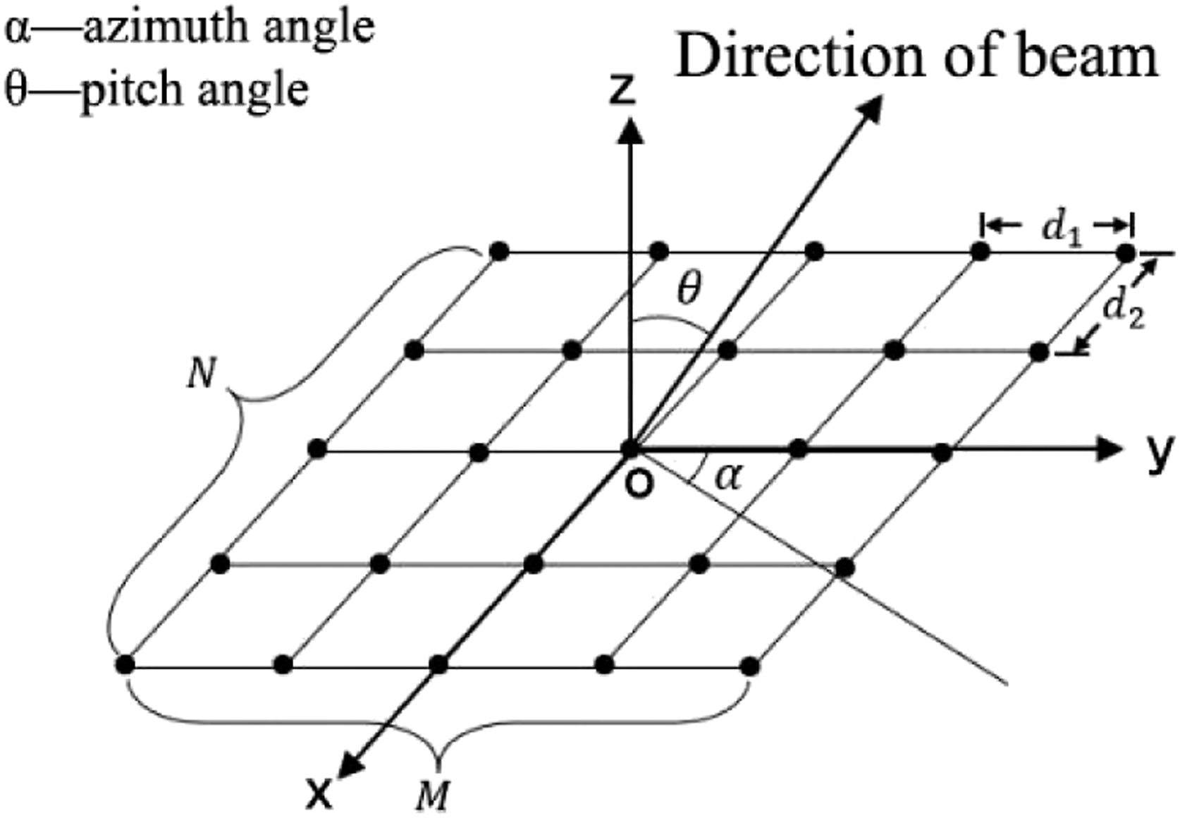
From equation (7), it can be seen that the directivity of plane loudspeaker array is related to M, N,
Then, the sound pressure at a certain point is
The feedforward FxLMS ANC system based on phased-array is shown in Figure 3. Feedforward filtered-x least mean square active noise control system based on phased-array.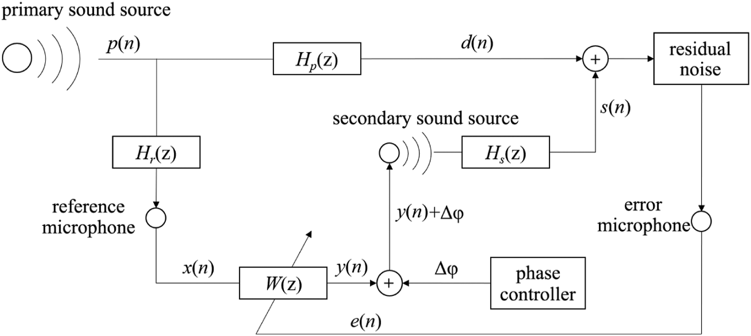
In Figure 3, x(n), y(n), s(n), d(n), e(n), and Δφ are the reference signal, secondary signal, canceling signal, desired signal, residual error, and the phase difference.
Since the phase is only related to the deflection angle and does not participate in the calculation of the ANC, the system is still a single-channel system. From Figure 3, the residual error of ANC is

When performing noise control, the minimization goal J(n) is to adaptively converge with the residual error of the microphone, that is,

The filter coefficients are updated according to the steepest descent method. The weight vector of the filter with length L at the time n is

and the update equation is

where
3. Sound field simulation analysis of ANC
Owing to the increased energy of the sound field, secondary sound sources will cause interference in the sound field. Analyzing the sound field after ANC helps to optimize the control system and reduce the adverse effects of non-control areas. When applying ANTC in three-dimensional space, the impact on other areas of the sound field should be as small as possible.
3.1. Single secondary source interference
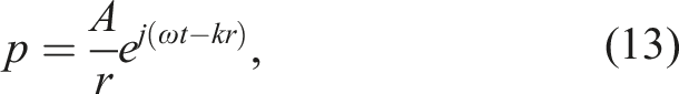
ANC is mostly used for low intermediate-frequency noise. This type of noise has a long wavelength. When the size of the sound source is small, it can be modeled as a point source. When a non-directional point source is used for single-channel ANC, the reflected wave of the source is ignored in the free field, and the sound pressure p at a point in the space is
Single-channel ANC controls the noise generated by a primary source through a secondary source. Figure 4 shows the spatial sound field superposition of dual sound sources. The sound pressure of the primary source at a certain point in space is given by equation (8) Superposition of the sound fields of dual sound sources in space.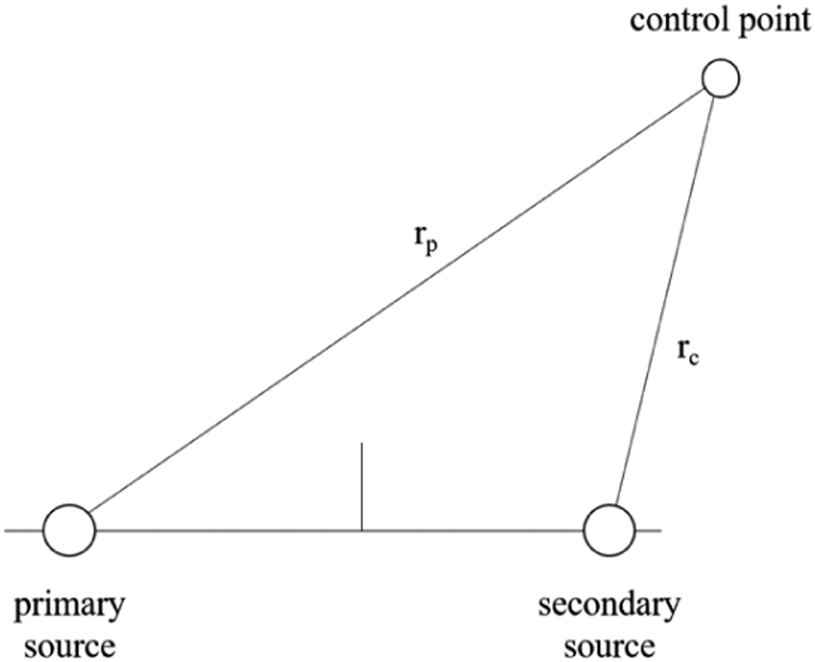
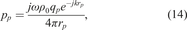
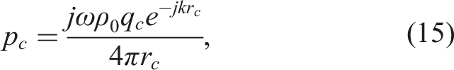
The sound pressure produced by the secondary sound source at this point is
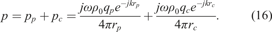
Sound waves in air interfere linearly, and thus, the sound pressure of the primary and secondary sources can be linearly superimposed at this point:
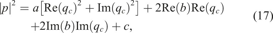
The control function of the system minimizes the sound pressure at the control point, which is equivalent to minimizing its square, and is given by
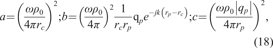
From equation (13), when the real part and the imaginary part of the gradient are both 0, it have
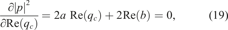
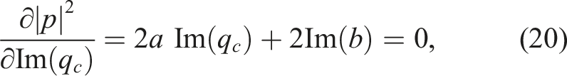
Thus, the best secondary sound source intensity is
From equation (21), the intensity of the secondary sound source to be controlled is related to the distance (r c /r p ). When the sound pressure phase difference between the secondary and primary sound sources at this point is 180°, destructive interference occurs at the control point. The sound radiation of the point secondary source is the same in all directions. Canceling interference occurs at certain positions in space, while constructive interference occurs in other positions, resulting in higher sound pressures in some areas.
To analyze the sound field characteristics of the ANC system, a cubic volume of 3 m × 3 m × 3 m was selected in the free field, whose medium was air, with density ρ0 = 1.2041 kg/m3 and sound velocity c0 = 343.24 m/s. A Cartesian coordinate system was established with the center of the volume as the origin. The primary sound source was a point source; the source coordinates were (1.5, 0, 0) m, the source frequency was f = 300 Hz, and the source power was 1 W. The secondary source was an identical point source with coordinates (0, 0, 1.5) m.
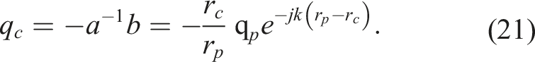
Figure 5(a) shows the sound field plane where the primary source was located before control. The sound pressure level (SPL) at the origin was 106.1 dB, and the spatial average SPL was 97.0 dB. The control strategy of the system is to minimize the average sound pressure in the quiet control area. The origin of the area was selected as the noise control point, and the size of 1/6 of the wavelength was taken as the maximum size of the quiet zone, and used equation (21) to obtain the optimal intensity of the secondary source. The SPL after control is shown in Figure 5(b). Spatial sound pressure level before and after active noise control of a single secondary source; (a) before control and (b) after control.
After control, the SPL at the control point was reduced to 83.1 dB. Owing to the additional secondary source, the total energy in the space increased. The average SPL in the space rose from 97.0 dB to 102.3 dB. The radius of the quiet zone near the control point, where the SPL was reduced by at least 10 dB, was 6.5 cm. Figure 5(b) indicates that the SPL of more non-control areas significantly increased due to constructive interference.
Because the sound field generated by the primary source and the secondary source was symmetrical, a “mute band” with low SPL appears on the symmetry axis of the space sound field. Figure 5(b) shows that the SPL of area ① near the secondary source increased by 19.8 dB; the average SPL of area ② increased by 12.8 dB; and the average SPL of area ③ increased by 7.5 dB. Besides the control points, the SPL of some other areas also decreased due to canceling interference; for instance, the average SPL of area and ④ decreased by 8.6 dB.
Therefore, after using an additional source for ANC at a certain point, while the noise at the control point was reduced, the sound field in other area became uneven and slightly increased. Although the SPL in some areas decreased, the average SPL in the space increased.
3.2. Array secondary source interference
When using the DASP for ANC, replace the secondary source shown in Figure 5(b) with an array source. DASP is composed of nine-point sources in a 3 × 3 grid with identical excitation. Therefore, the array source is still a single-channel system. The distance between the array elements is 0.2 m, and the center coordinates of the array are (0, 0, 1.5) m as before.
The parameters and location of the primary source were the same as in Section 3.1. Similarly, the origin was selected as the control point with the DASP as the secondary source for ANC. As shown in Figure 6(c), after control with an array source, the SPL of the control point decreased to 72.7 dB with noise reduction of 33.4 dB and quiet zone radius of 10.8 cm. The total sound power of the array was 0.132 W, which is only about 1/9 of the single point. Thus, the control effect of the array was better than that of the single point. Sound pressure level before and after control with different secondary sources; (a) original, (b) single, and (c) array.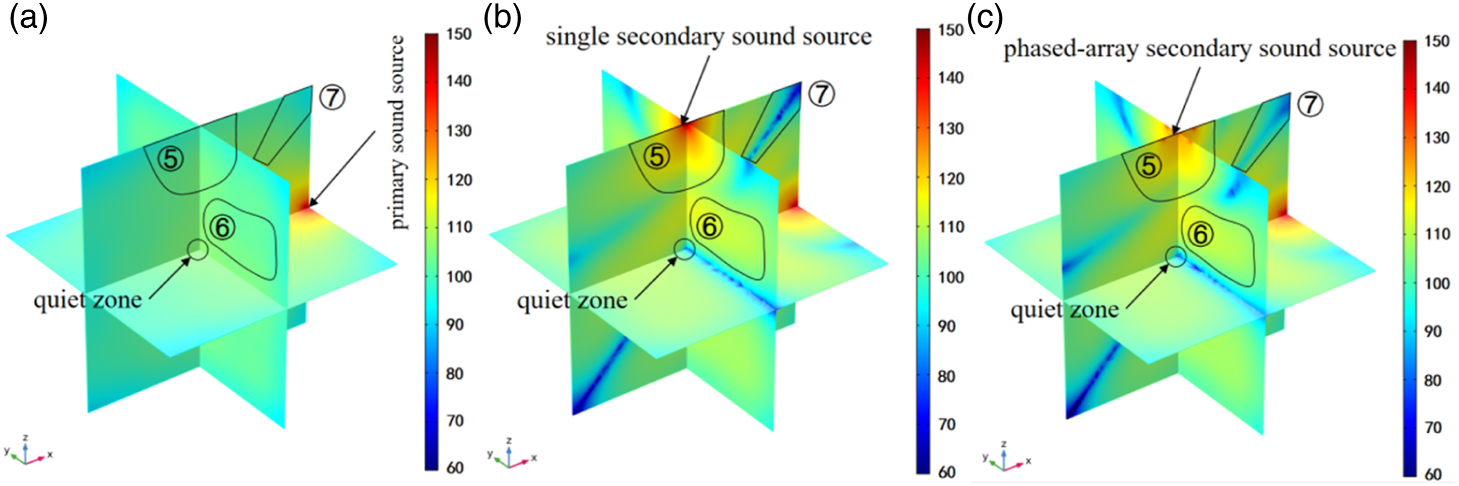
Figures 6(b) and(c) show the spatial sound fields after using the single source and the array source for ANC. Compared with a single secondary sound source, when the DPSA secondary source was used, the average SPL of the area ⑤ decreased from 124.2 dB to 115.4 dB, the difference is 9.2 dB; the average SPL of the area ⑥ decreased from 114.5 dB to 109.8 dB, decreased by 4.7 dB; the average SPL of area ⑦ increased from 81.7 dB to 88.5 dB, increased by 6.8 dB. These values are closer to the original sound field without secondary sound source. Besides, when the DPSA secondary source was used, the average SPL of whole space only increased from 97.0 dB to 99.4 dB, increased only by 2.4 dB. That was less than the increase of 5.3 dB using a single secondary sound source. Therefore, the control system added less sound energy with the array source and had less adverse effects in the space’s sound field. For the control area, the noise reduction and quiet zone were larger, and the control effect was better; for the non-control area, the deviation from the average SPL of the sound field without the secondary source was smaller, and the adverse effect was also smaller.
3.3. ANC in different directions
One can implement ANTC by using the phased-array method to deflect the directivity of the secondary source of the array. It was verified through simulation. The control points were A (−0.866, 0, 0) m and B (−1.5, 0, 0) m, and the angles between them and the center of the array were 30° and 45°. Figure 7 shows the SPL after control. Sound pressure level after control; (a) control point A (single), (b) control point A (array), (c) control point B (single), and (d) control point B (array).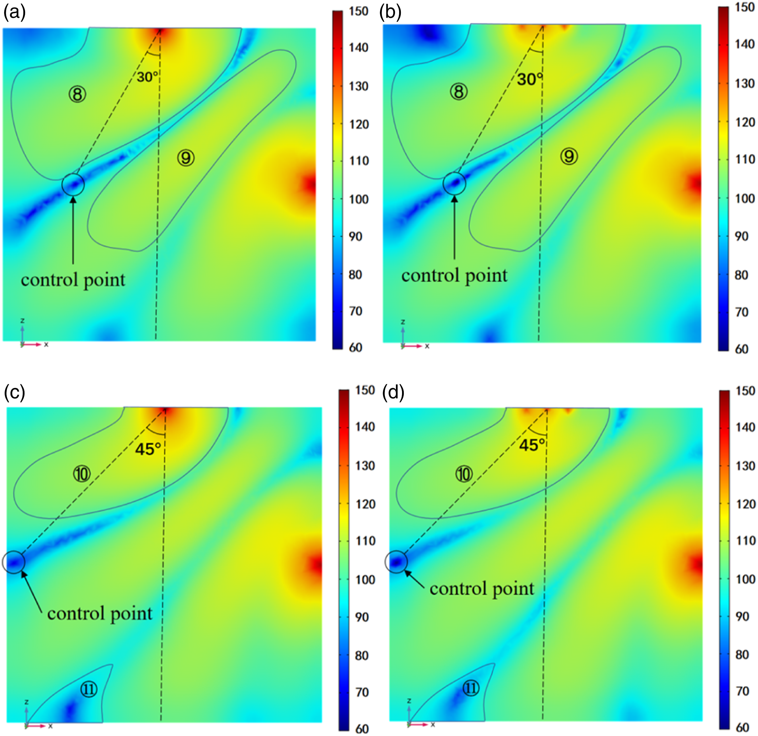
Comparison of sound pressure levels in various areas in the space after active noise control.
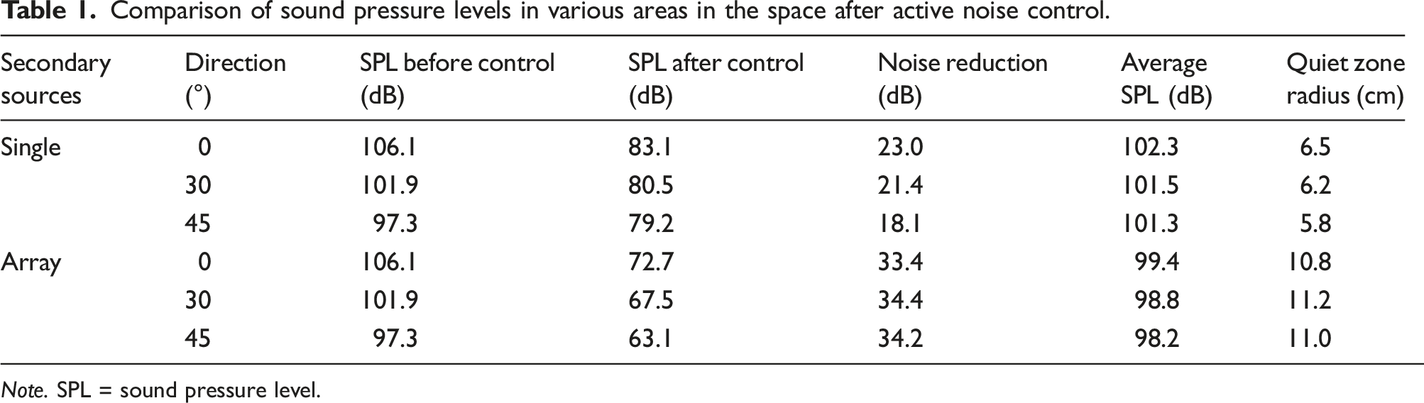
Note. SPL = sound pressure level.
Table 1 shows that owing to the additional secondary sources, the average SPL of the space increased. Because of the low sound power of the array, the spatial SPL rose less with the single-point control; when the control direction was changed from 0° to 30° and 45°, as the angle of the control direction increased, the control effect and the quiet radius zone of the single-point control gradually deteriorated. When a DPSA was used for ANC, the angle of the control direction has almost no effect on the noise reduction and the quiet zone radius of the control point. Therefore, when the positions of the primary sound source and the secondary sound source are relatively fixed, using the DPSA as the secondary source can carry out ANTC in a large space through more flexible adjustment of the control area and direction, and can change the directivity without changing too much control effect more flexibly. The control effect is better than using a single point source.
4. Experiment and analysis of ANC
4.1. Array secondary source
The 4 × 4 array secondary source used in the experiment was composed of 16 loudspeakers with calibrated amplitude and initial phase and their matching power amplifiers. The array was fixed on a rigid board, and according to Nyquist sampling theorem, the array element spacing should be smaller than half of the wavelength. According to the experimental frequency range of 300–450hz, the array element spacing 20 cm is selected. It should be noted that although the spacing is slightly greater than half of the wavelength when the frequency is 300 Hz, the influence of grating lobe is not obvious, as shown in Figure 9. A piece of 20 cm thick polyurethane was used to reduce the sound reflection from the ground on the back side.
The directivity of the array was measured in a semi-free-field anechoic room with a background noise of 25dB. The array was placed at the center of a turntable, and a semicircular steel frame with a radius of 1.8 m was built above it. A total of 13 microphones were set every 15°. The array was rotated 15° each time by the turntable, so that the SPL above the array could be measured within the range of 180° pitch angle and 360° azimuth angle, see Figure 2 for an example. Figure 8 shows the experimental setup. Photograph of directivity experiment with array secondary source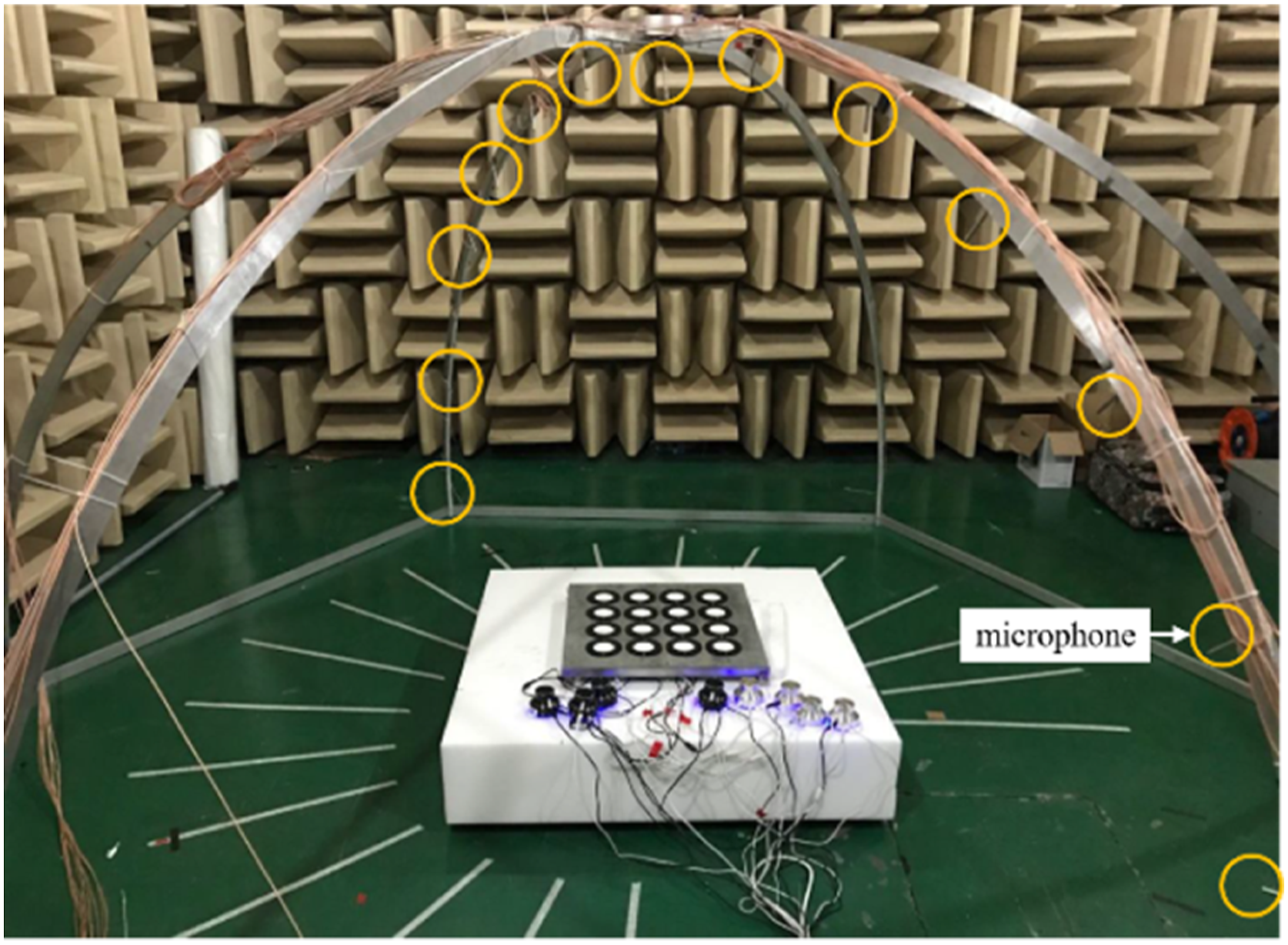
The measurement value was fitted to a smooth curve and performed normalization processing. When the frequency f = 300 Hz, the directivity result of the array is shown in Figure 9. Directivity results of the array; (a) simulation (no deflection), (b) experiment (no deflection), (c) simulation (30°, 45°), and (d) experiment (30°, 45°).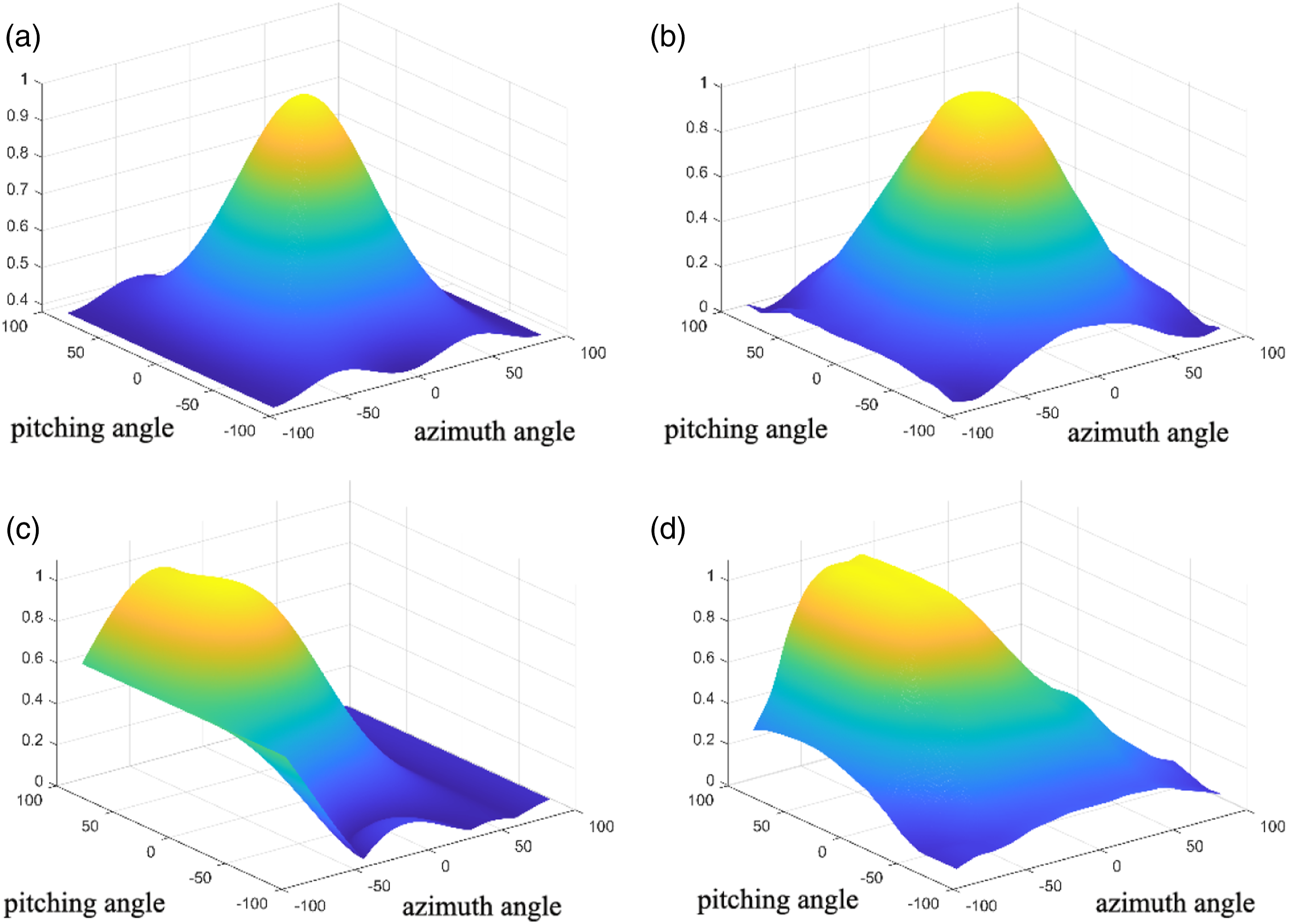
The simulation and the test were very consistent. This means that the array can scan the space of the main lobe deflection, and it can be used as a secondary source in different directions or as ANTC on a target in space.
4.2. Experiment system
To further verify the following noise reduction effect of the array and evaluate its impact on the sound field, an experimental system was built in a semi-free-field anechoic chamber to study the effect of ANC with an array source. The array was placed on the ground with the primary source at a distance of 2.0 m from the center of the array at a height of 1.0 m. The primary noise to be controlled was a single-frequency signal from a signal generator, amplified by a power amplifier. The reference microphone was set 0.1 m in front of the primary source; control point 1 was set 2.0 m directly above the array sound source (2.2 m from the ground), and control points 2 and 3 were set at 2.0 m, 30° and 45° from the center of the array. Four microphones were evenly arranged in a circle of radius 1.0 m, a height of 1.5 m from the center of the array to acquire the SPL at other locations in the space during ANC. Figure 10 shows the system layout. Diagram of active noise control experimental system.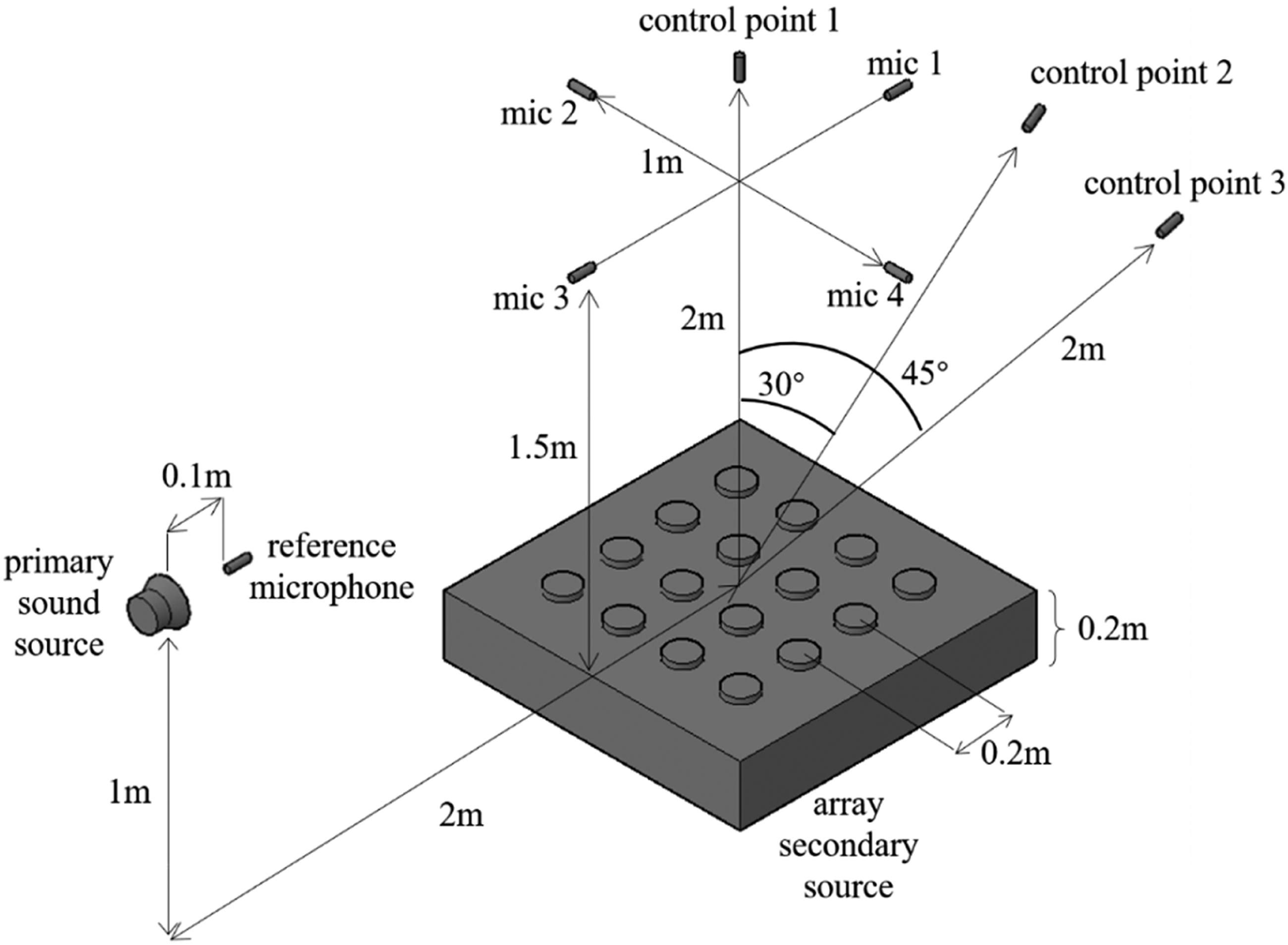
Some other relevant parameters in the experiment are set as follows: the filter length for X-LMS was 200, step size was 2.0*10−5; the sample rate was 1000, sample size was 200; and the white noise amplitude was 100mV, filter length for impulse was 1000, the step size for impulse was 0.002.
The single source and the DPSA source were used to control the noise at the control point with different frequencies of the primary signal. Using the system shown in Figure 10, two sets of experiments were carried out, as follows. (1) Comparison of control effects with two kinds of secondary source
The single source and the DPSA source were used to control the noise of control point 1. From the experimental results of the two types, the noise reduction effect and the influence of other areas were evaluated. (2) ANC in different spatial directions with two kinds of secondary source
The single source and the array source were used to control the noise of control point 2 (with 30° pitch angle) and control point 3 (with 45° pitch angle) with the phased-array method. From the experimental results of the two types, the noise reduction effect and the influence of other areas were evaluated.
The experiment was conducted with a feedforward control system. Before the experiment, an adaptive offline secondary path from the secondary source to the error microphone was needed to be established by the white noise method, which can greatly impact the system (Casciati et al., 2012). After several pre-experiments, the optimal secondary path was selected for experimentation, and the same coefficient μ was used in the experiments under the same working conditions.
In general experiments, the acoustic feedback effect of the reference sensor in feedforward ANC system should be taken into account. The state of the art in acoustic feedback control solutions are divided into four classes: phase-modulation (PM) methods, gain reduction methods, spatial filtering methods, and room modeling methods (Van Waterschoot and Moonen, 2010). In fact, the secondary sound source array used in this paper can concentrate the output sound energy in the main lobe beam range, so as to reduce the impact on other areas, it also reduces the acoustic feedback effect.
4.3. Experimental results and analysis
In the experiment, three single-frequency tones of 300 Hz, 400 Hz, and 450 Hz were selected as the primary noise to be controlled. First, two secondary sources were used to control the noise of control point 1, and the SPL data of each microphone were collected. The initial value of the SPL collected by each microphone was used as the reference value for normalization. Figure 11 shows the normalized image of the SPL with single-point and array sources at 300 Hz. Comparison of active noise control effects; (a) single and (b) array.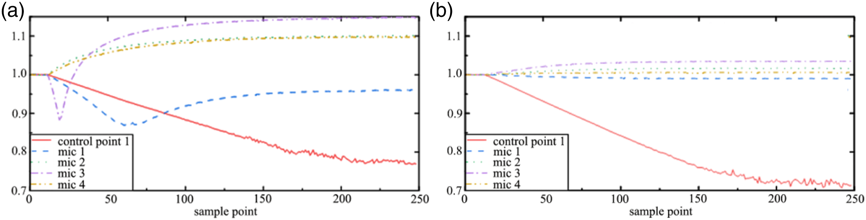
From Figure 11(b), at control point 1, the control effect of the array source was better than the single-point one. In other areas, because of the additional sources, canceling interference occurred at microphone 1 far from the primary source, and the SPL decreased; meanwhile, constructive interference occurred at microphone 3 close to the primary source, and the SPL increased. Microphones 2 and 4 were placed symmetrically, so the SPL increased with the same trend.
Change in sound pressure level at control point 1 and other microphone (unit: dB).
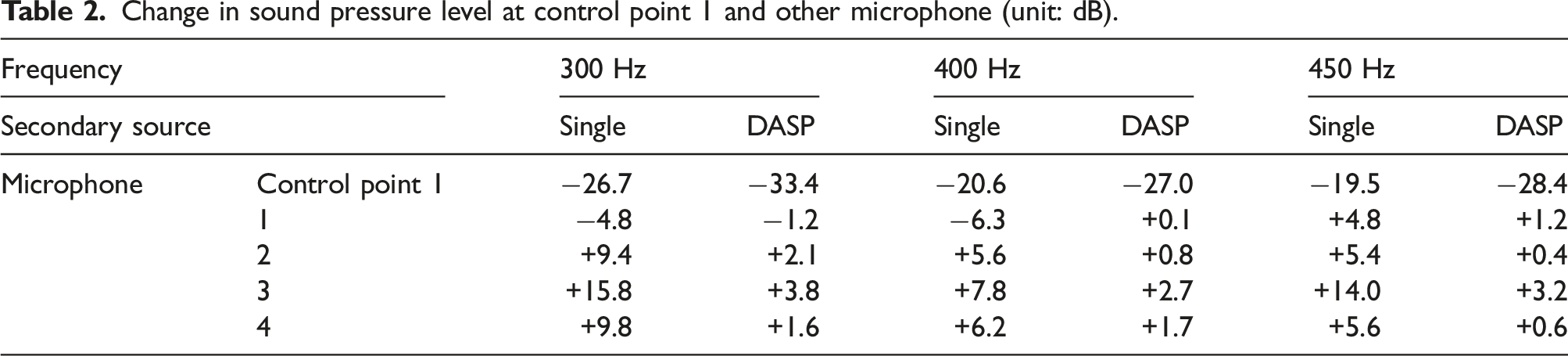
From Table 2, when the noise of control point 1 was controlled, the noise reduction of the DASP increased by 6.7 dB (@300 Hz), 6.4 dB (@400 Hz), and 8.9 dB (@450 Hz) over the single-point source. The SPL changes of microphones 1–4 were also smaller, with a maximum increase of only 3.8 dB. Correspondingly, with the single-point method, the maximum increase was 15.8 dB (@300 Hz), while the array increased by only 3.8 dB (@300 Hz). The experimental results were consistent with the simulation results, indicating that the array as secondary source in an ANC system gives a better noise control effect, and has less influence on other areas.
ANC experiments were conducted in different spatial orientations to test the spatial ANTC ability of the array. The single-point source and the array source were used to control the noise at control points 2 and 3 at 300 Hz, 400 Hz, and 450 Hz. Then, the noise reduction effects were evaluated in different directions. The feedforward adaptive noise reduction system was still used for system testing and feasibility analysis.
The SPL of each microphone was collected and normalized during the control process. Figure 12 shows the normalized SPL of control points 1, 2, and 3, with control directions 0°, 30°, and 45° at 300 Hz. Active noise reduction results of different control directions.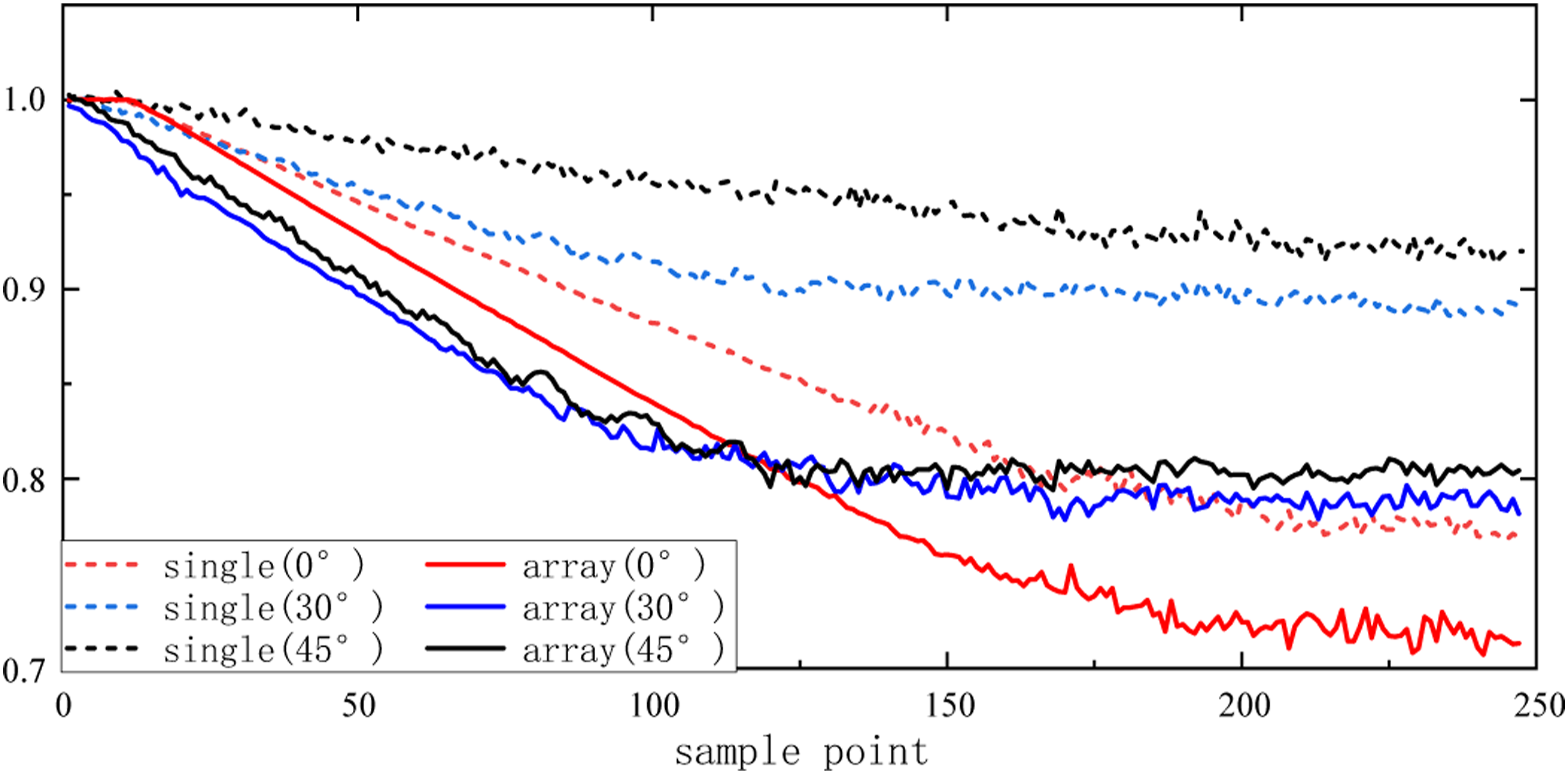
Average noise reduction of different frequencies when the control direction was 0°, 30°, and 45° (unit: dB).
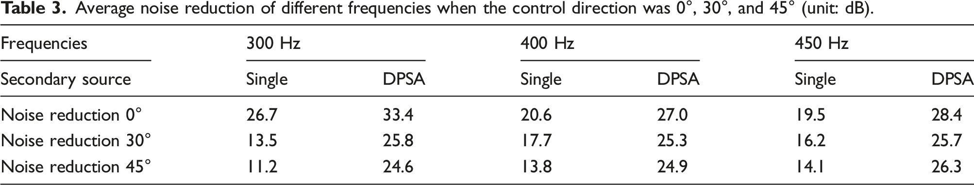
From Table 3, the noise reduction of the array increased by 6.7 dB (@300 Hz), 6.4 dB (@400 Hz), and 8.9 dB (@450 Hz) over the single point when the control direction was 0°. When the control direction was 30°, the noise reduction of the array increased by 12.3 dB (@300 Hz), 7.6 dB (@400 Hz), and 9.5 dB (@450 Hz) over the single point. When the control direction was 45°, the noise reduction of the array increased by 13.4 dB (@300 Hz), 11.1 dB (@400 Hz), and 12.2 dB (@450 Hz) over the single point.
The noise reduction of the DPSA was much better than the single-point source when the control direction was not along the axis of the secondary source. When the angle of the control direction increased, the advantage of this noise reduction method increases. When the single point was used for ANC, the larger the control angle, the smaller the noise reduction effect, limiting its usefulness. When the array DPSA was used for ANC, the noise reduction effect was always above 24.5 dB, so its noise reduction effect was better than the single-point method.
5. Conclusion
When performing ANC in a certain area, the secondary source will reduce the noise in this area and change the SPL of other areas. Traditional non-directional secondary source has a smaller noise control range and lower noise reduction in an ANC system. This article proposed a new method using the DPSA as the secondary source to improve the noise reduction of the ANC system and reduce its adverse effects on other areas. The experiment used a feedforward method to verify feasibility, which used the phased-array method to achieve better tracking noise reduction in the control area. The system can combine with tracking equipment or virtual sensing technology to achieve a better ANTC effect. Note that because the experimental environment is not a completely ideal environment, the primary source has a certain size and cannot be completely regarded as a point source, and the experimental results produce certain errors.
The results of both the simulation and the semi-anechoic room experiment show that the control effect of the array is better and the influence on other areas is smaller. It has the advantages that follow: (1) The noise control effect of the DPSA is better than the single point as the secondary source; (2) the sound energy of the DPSA is more concentrated, so the source intensity required by the secondary source is smaller, and the impact on other areas is smaller. It can improve the problems of uneven spatial sound field and increased SPL caused by the secondary sources; and (3) the phased-array method can be used to accurately deflect the main lobe beam. The system can be combined with tracking equipment to achieve effective active noise tracking control in a larger space.
Footnotes
Acknowledgments
Author Contributions
Conceptualization, Jun Tang; investigation, Xi Liang; methodology, Tao Wang; software, Tao Wang, Yutian Bai; interpretation of data, Tao Wang, Xi Liang, Lei Yan; analysis, Tao Wang, Xi Liang, Lei Yan; writing—original draft preparation, T. Wang
Declaration of conflicting interests
The author(s) declared no potential conflicts of interest with respect to the research, authorship, and/or publication of this article.
Funding
The author(s) disclosed receipt of the following financial support for the research, authorship, and/or publication of this article: This work was supported by the National Key R&D Program of China (Grant No. 2020YFA040070).