
Abstract
The synchronous disturbance acting on the magnetically suspended momentum wheel (MSMW) would affect its suspension stability and control accuracy, so a varied-gain compound model is proposed to attenuate the synchronous disturbances of the MSMW with varying rotating frequencies. The disturbance frequency is varying with the rotating frequency of the MSMW, the gain and frequency of the disturbance observer are regulated to maintain the asymptotic stability, and the feedback gain of the state feedback is scheduled to avoid the complex repeated acquisition of control parameters. Finally, the numerical simulations and experiments are performed to validate the effectiveness of the proposed varied-gain control model. The results indicate that the proposed control model could effectively attenuate the synchronous disturbances and maintain the asymptotic stability of the MSMW when the rotating speed changes.
Keywords
1. Introduction
The momentum wheel is widely used as the attitude actuator to exchange the momentum with the spacecraft. For the mechanical momentum wheel, the imbalance vibration is the main disturbance to affect the attitude accuracy of the spacecraft. For the magnetically suspended momentum wheel (MSMW), the active magnetic bearing (AMB) is adopted to suspend the wheel rotor, and the mechanical contact between the rotor and stator is avoidable (Van Verdeghem and Dehez, 2021; Xiang and Wong, 2021). The MSMW has the advantage on the micro-vibration because the imbalance vibration could be actively controlled by the magnetic force of the AMB (Yu et al., 2017). Moreover, the non-contact feature of the MSMW also offers many advantages such as the absence of friction, the longevity, and the high precision in spacecraft application (Tsiotras et al., 2001). In order to provide large momentum to realize the attitude control of the spacecraft, the MSMW can not only change the rotating speed to generate the reaction moment but also regulate the deflection angle of rotor shaft to output the tilting moment, so the three-dimensional torques are generated (Seddon and Pechev, 2009; Xiang et al., 2022). Because the deflection engenders high bandwidth and high precision torque, the MSMW has potential applications to improve the attitude stability of spacecraft (Sawada et al., 2001; Yu et al., 2015).
The dynamic imbalance caused by the mismatch between the inertial axis and geometric axis would cause the synchronous disturbance to the MSMW. The numerous methods have been developed to suppress synchronous disturbances of the AMB-rotor system. The variable angle compensation algorithm was designed to mitigate the synchronous vibration of the AMB-rotor system based on the real-time feedback of rotor position (Gong and Zhu, 2020). The imbalance mass was virtually compensated by the auto-balancing method (Zheng and Wang, 2021), but this method needs the precise calculation about the mass imbalance. Sun et al. proposed a filter-based adaptive back-stepping model to stabilize the MSMW under an unknown disturbance (Sun et al., 2015), but the control accuracy of rotor position is needed to be further improved. In addition, a feed-forward method was applied to suppress the synchronous disturbance (Shi et al., 2004), and the synchronous disturbance was effectively attenuated by adjusting the amplitude and phase of injected synchronous signal. Xu et al. designed an adaptive method to adjust the coefficients of notch filter (Xu et al., 2018). Zheng et al. designed a phase-shift notch filter to maintain the stability of closed-loop system over a wide range of frequencies (Zheng et al., 2016). The above-mentioned notch filter models were designed for the constant-frequency synchronous disturbances of the AMB-rotor system, so the disturbance attenuation cannot be guaranteed for a broad range of rotating frequency.
Furthermore, a nonlinear disturbance observer was designed to estimate the mismatch disturbances between rotor and stator in the MSMW (Niu et al., 2017). Liu et al. designed a sliding mode observer to improve the disturbance attenuation of the AMB system (Liu and Liu, 2016). Schuhmann et al. designed an extended Kalman filter to estimate the synchronous disturbances caused by rotor imbalance (Schuhmann et al., 2012). However, the above-mentioned disturbance observer models are only effective when the frequency of synchronous disturbance is constant. Moreover, because the parameters of the AMB-rotor system and the synchronous disturbances would vary with the rotating speed, the parameters of the disturbance observer should be intermittently recalculated. Jiang et al. thus designed a method to compensate the disturbance based on the position of the imbalanced rotor mass (Kejian et al., 2015). This method doesn’t need the recalculation because the imbalanced rotor mass does not vary with rotor speed. For the linear parameter varying system with a time-varying input delay, the gain-scheduled controller was used to maintain the system stability (Sename et al., 2013; Wang et al., 2007). A gain-scheduled H ∞ control model was applied to an AMB-rotor system for rejecting imbalance disturbances (Balini et al., 2012). However, the deflection motions of the flywheel rotor around the radial axes are not analyzed and suppressed, but disturbances caused by the deflection motions would affect the stable suspension and the moment precision of the MSMW.
Above all, a varied-gain disturbance observer is designed to suppress deflection of the MSMW suffering the variable-frequency synchronous vibration, and the variation of the rotating speed is regarded as the system uncertainty to affect the synchronous vibration. A precise dynamic model of the deflection control is established, and a gain-scheduled method is used to ensure the asymptotic stability of the closed-loop system with varying rotating frequency. Compared to above-mention methods for mitigating the varying-frequency synchronous vibration of the MSMW, the contributions of this article are listed as follows: (1) The asymptotic stability of the MSMW considering the variation of the rotating speed is guaranteed, and the repeat complex calculations to achieve the stability conditions are avoided. (2) The synchronous vibration with the varying frequencies is attenuated, and the suspension precision of the MSMW is improved by applying the disturbance observer method based on the precise dynamic modeling of the AMB.
This article is organized as follows. In Section 2, the dynamic models and synchronous vibration are analyzed and modeled. In Section 3, the designed varied-gain disturbance observer is presented, and the system stability is verified. In Section 4, the simulations were conducted. The experimental results are discussed in Section 5. Finally, the conclusions are provided in Section 6.
2. System modeling of MSMW system
2.1. The structure of MSMW system
As illustrated in Figure 1, the rotor shaft of the MSMW is suspended by the AMB units at the upper end and lower end of the stator part, and the non-contact eddy current sensors could measure the rotor position. Furthermore, the measured displacement signal is transmitted to the AMB controller through the signal conditioning circuit, so the controller could regulate the rotor position by tuning the control currents of the AMB. The suspension stability and control precision of the MSMW are mainly affected by the dynamic model of the rotor shaft and the force model of the AMB unit, and the non-parallelism of the inertial principal axis and the rotating axis of the rotor shaft would generate synchronous disturbance to affect the suspension stability and control precision. The structure of the magnetically suspended momentum wheel (MSMW).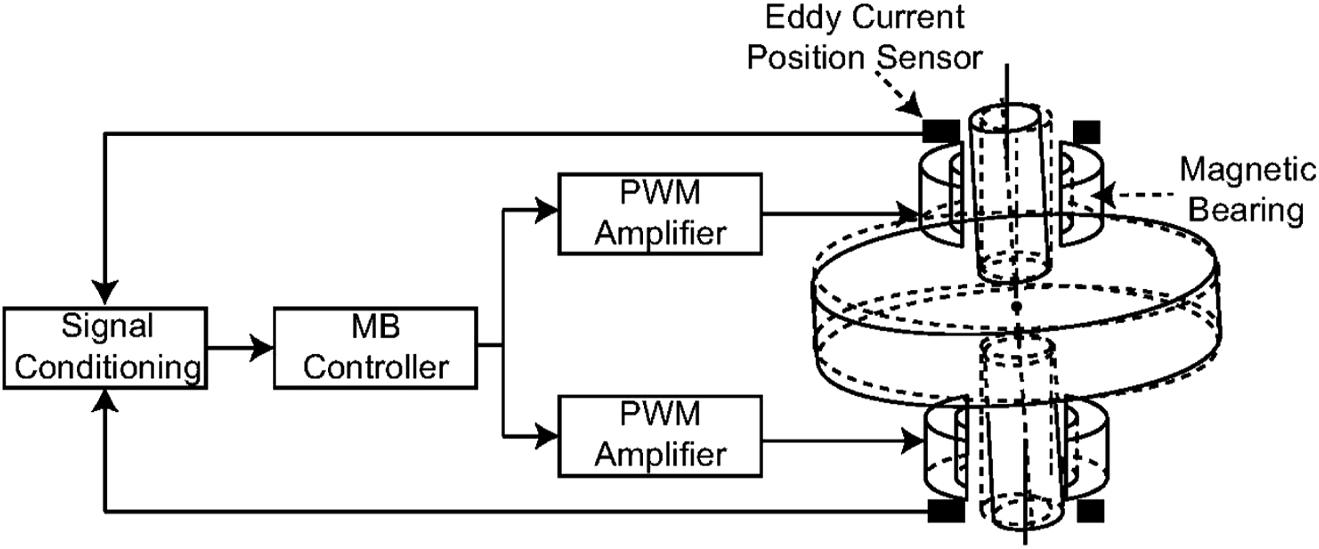
2.2. Frame definition of MSMW system
To develop the dynamic model of the MSMW, the five frames of the AMB-rotor system in Figure 2 are defined: one frame of the AMB, three frames of the rotor, and the inertial frame of the equator. Figure 2(a) shows the typical structure of the MSMW, and the 2-degree-of-freedom (2-DOF) translation and the 2-DOF torsion are controlled by the pairs of upper and lower AMB units fixed in the wheel body. The frames of the MSMW: (a) the normal structure of the MSMW and (b) the static frames of the MSMW.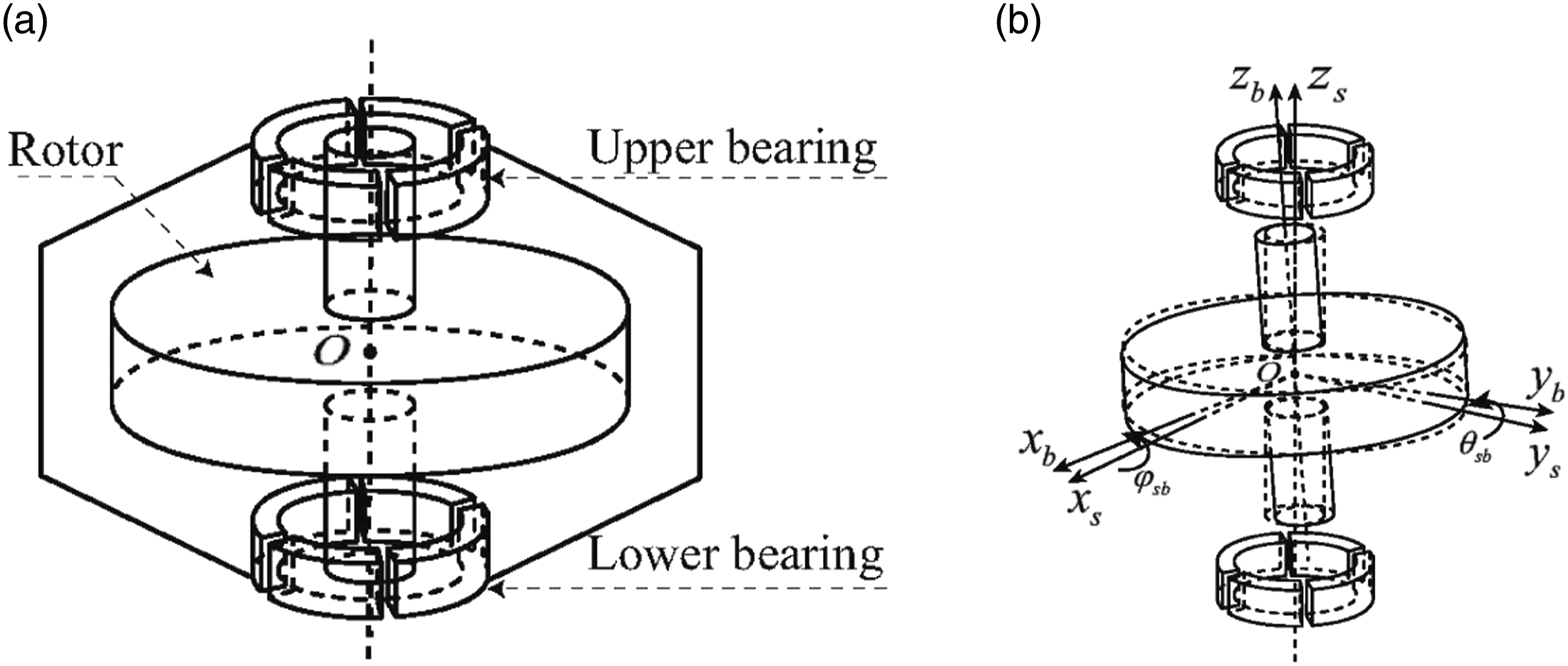
In Figure 2(b), the two static frames of the rotor shaft are defined as follows: (1) The geometric frame of AMB (ox
s
y
s
z
s
): the origin is the geometric midpoint between the lower AMB and the upper AMB, the z
s
-axis lies along the central line of the lower and upper AMB units, the x
s
-axis is perpendicular to the z
s
-axis, and the y
s
-axis is perpendicular to the x
s
-axis and z
s
-axis obeying the right-hand rule. (2) The body frame of rotor shaft (ox
b
y
b
z
b
): the origin is the geometric center of the rotor shaft, the z
b
-axis lies along the symmetrical axis of the rotor shaft, and the x
b
-axis and the y
b
-axis are perpendicular to the z
b
-axis and lie in the plane parallel to the disc plane of the rotor shaft.
The ox
b
y
b
z
b
and ox
s
y
s
z
s
are coincident when the translation displacements and deflection angles of the rotor shaft are ideally equal to zero. Thus, the three Euler angles between ox
s
y
s
z
s
and ox
b
y
b
z
b
can be defined as ϕ
sb
, θ
sb
, and ψ
sb
, where ϕ
sb
and θ
sb
are the deflection angles about the x
s
-axis and y
s
-axis, respectively, and ψ
sb
equals to zero. In Figure 3(a), the two frames rotating around the axial axis are defined as follows: (1) The inertial frame of rotor shaft (ox
g
y
g
z
g
): the origin is the center of mass of rotor shaft, and x
g
-axis, y
g
-axis, and z
g
-axis are the three perpendicular principal inertial axes of the rotor shaft. (2) The geometric frame of rotor shaft (ox
r
y
r
z
r
): the origin is the geometric center of the rotor shaft, the z
r
-axis lies along the symmetrical axis of rotor shaft, and x
r
-axis and y
r
-axis are perpendicular to z
r
-axis. (a) The rotating frames of the MSMW and (b) the relationship between the geometric frame of the AMB and body frame of the rotor shaft.
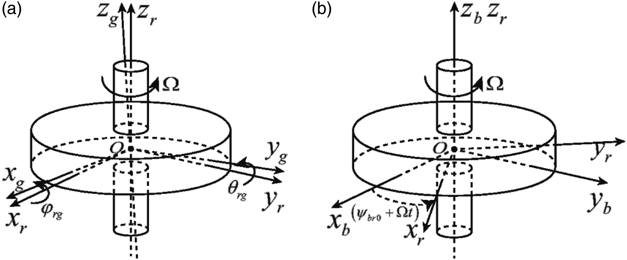
The frame ox r y r z r would rotate around the axial axis with the speed Ω. The three Euler angles between ox g y g z g and ox r y r z r are defined as ϕ rg , θ rg , and ψ rg . The ψ rg is equal to zero, and ϕ rg and θ rg presents the non-parallelism of the inertial axis and the geometric axis of the rotor shaft, both of which can be set as constants.
The relationship between frame ox b y b z b and frame ox r y r z r is illustrated in Figure 3(a). In detail, z r -axis is coincident with z b -axis, and the three Euler angles between the frame ox b y b z b and the frame ox r y r z r are defined as 0, 0, and ψbr0+Ωt, respectively. ψbr0 is the initial value.
3. Controller design of MSMW system
3.1. Modeling of AMB-rotor system
According to the frame definitions of the MSMW system in Figure 2 and Figure 3, φ
sb
and θ
sb
are the deflection angles about x
s
-axis and y
s
-axis, respectively. Defining i1 and i2 as the control currents of the AMB units, ks1 and ks2 are the deflection angle stiffness coefficients, and ki1 and ki2 are the current coefficients. There are

Moreover, J11 = J22 = J
r
and J33 = J
a
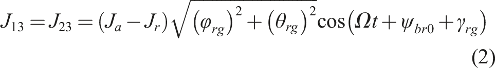
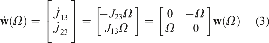
are the lateral and polar inertias of the rotor shaft, respectively. For the disturbance terms, the variation of the rotating speed could be regarded as one kind of the system uncertainties, and the additional synchronous disturbances varying the rotating speed is written into
The rotating speed Ω and deflection angles φ
sb
and θ
sb
are measurable, so the deflection velocities
3.2. Controller design of the AMB-rotor system
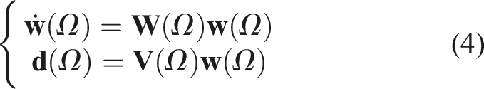
In (4), the parameters of the disturbance model are relative to the rotating frequency of the rotor shaft. If the rotating frequency is constant,
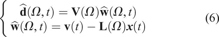
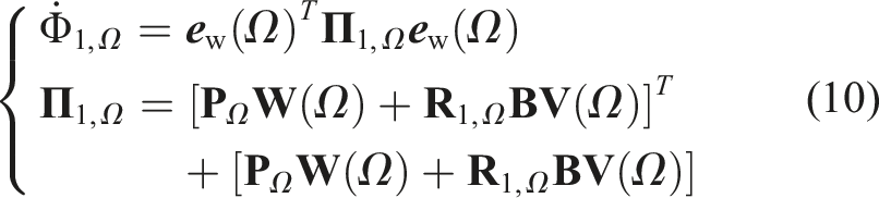
To design the disturbance observer for the rotating speed Ω, a 2 × 1 auxiliary state variable The deflection angles are measured by the displacement sensors, and the deflection velocities are calculated by differentiating the measured deflection angles. Thus, the disturbance observer is designed as
If a 2 × 4 real matrix
Let the observation error be The candidate Lyapunov function is Then, the derivative function of (9) is


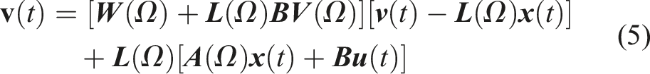
A compound control model combining the state feedback model and the disturbance observer is expressed as

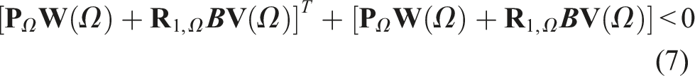
If a 2 × 4 real matrix The stability of the closed-loop system could be proven via the Lyapunov stability theory, and the proof process is given as follows:
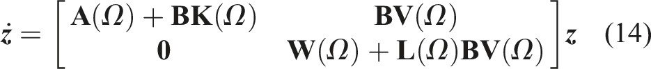
Substituting (11) into (1), the closed-loop system is rewritten to The candidate Lyapunov function is chosen as Then, the derivative function of (15) is


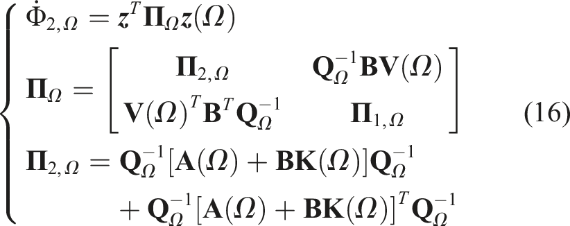
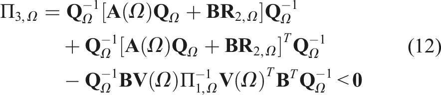
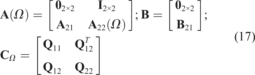
For the constant-frequency disturbance, the observer gain and the controller gain could be obtained by solving the linear matrix inequalities (LMIs) in (7) and (12). According to system model in (1) and disturbance model in (4), the system matrix Initially, the observer gain matrix If the observer gain
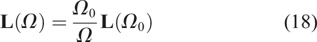

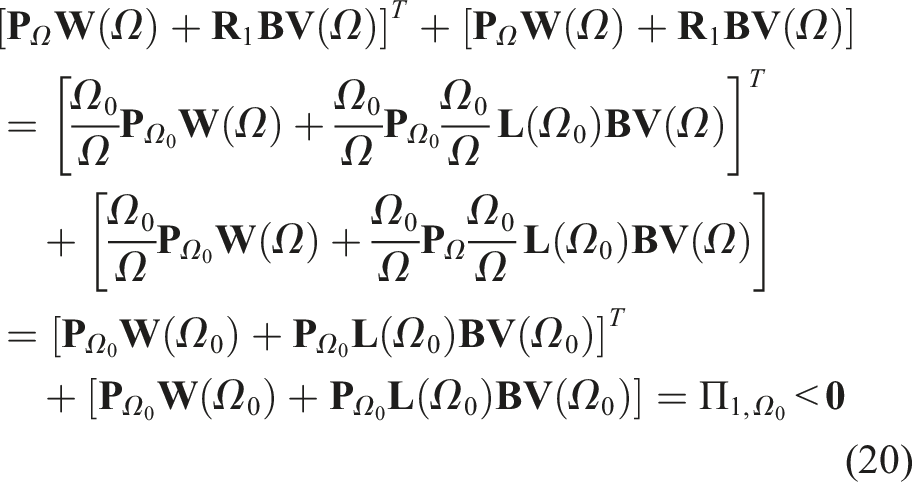
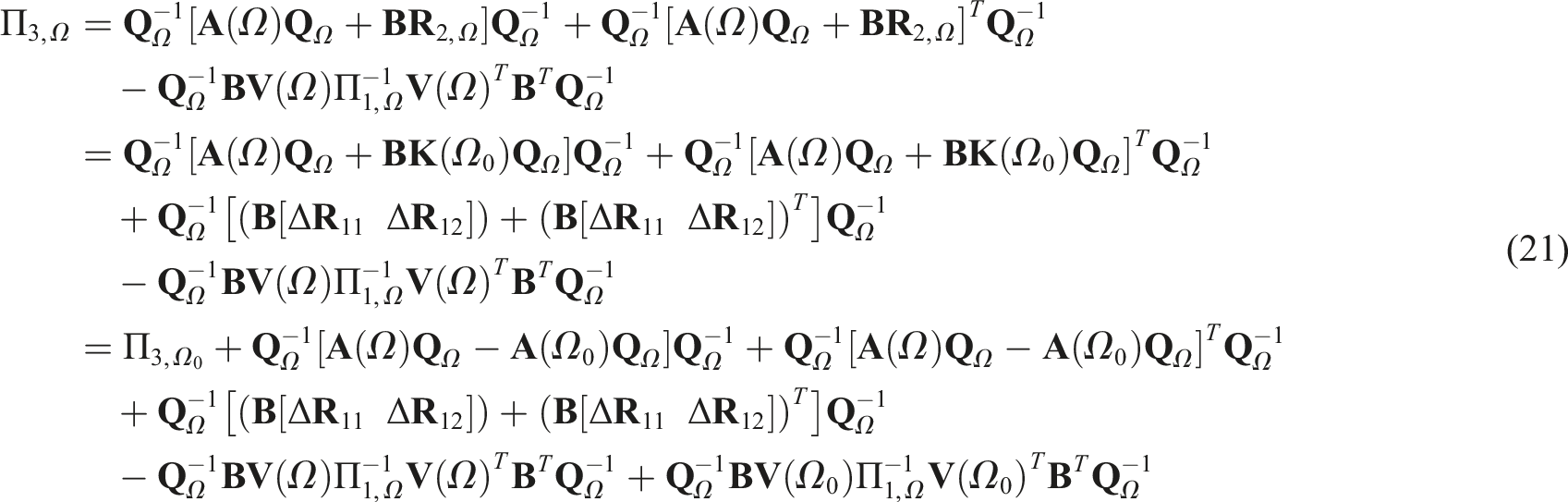
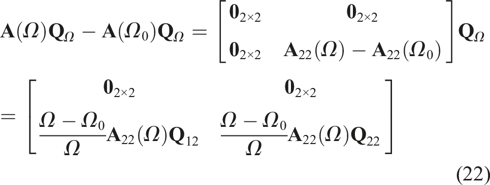
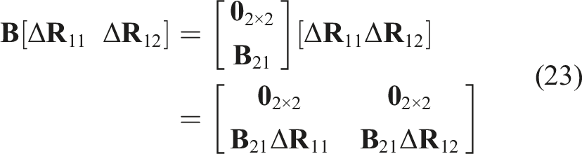
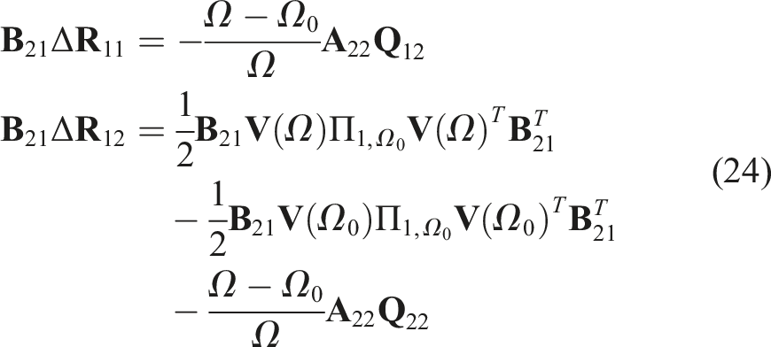
Defining (20) indicates that the observation error in (8) is asymptotically stable for the variable-frequency disturbance. Substituting (19) into (12), there is Based on the definitions of Δ By substituting (22) and (23) into (21), there is Therefore, the closed-loop system in (14) under the control law (11) with the gain (19) is asymptotically stable. Finally, the closed-loop control system about the deflection of the MSMW is illustrated in Figure 4, the rotating speed and the reference deflection angles are used as the system input, and then the deflection angles are the system output. Furthermore, the errors between the reference angle and the output angle are the input of the varied-gain disturbance observer, and then the control currents are generated by the power amplification unit. Finally, the control torques are outputted to suppress the synchronous vibration.

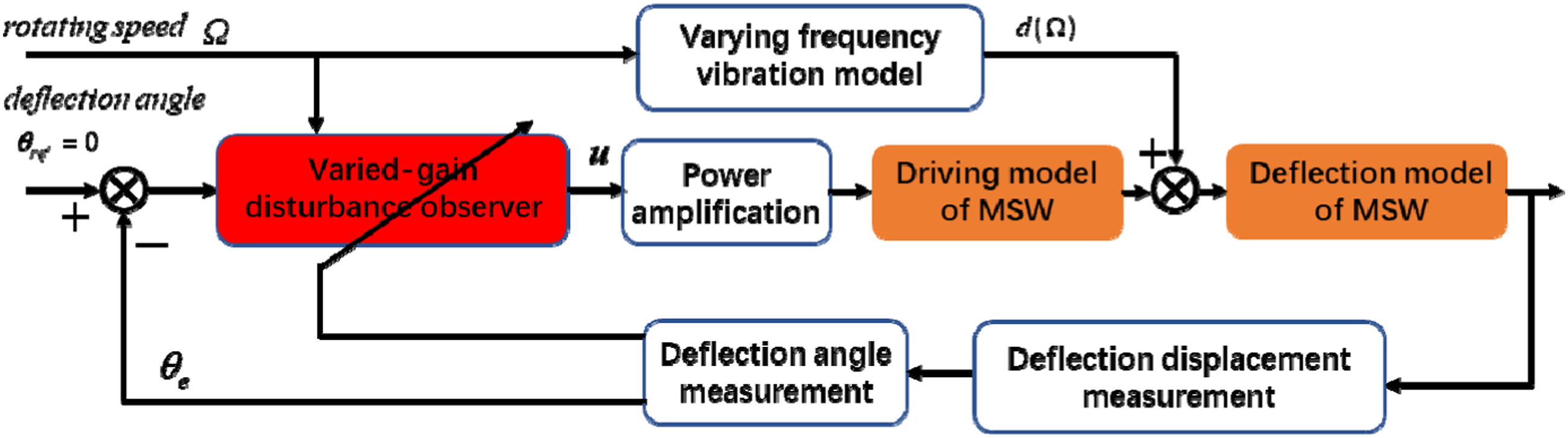
The deflection control model of the MSMW.
4. Simulations
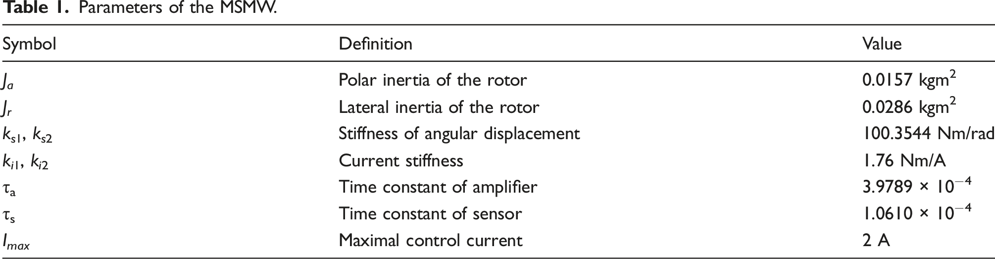
Parameters of the MSMW.
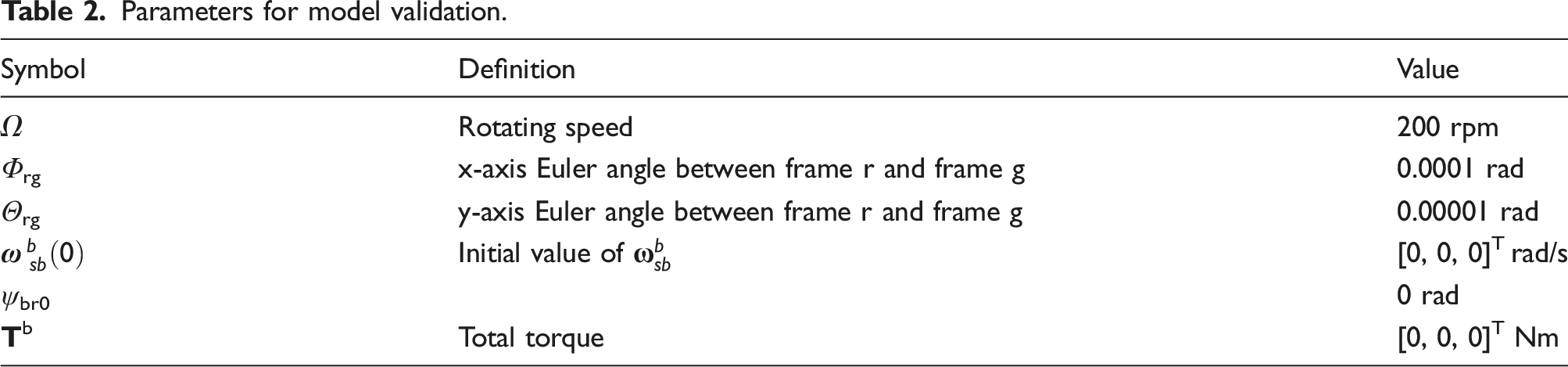
Parameters for model validation.
The velocities of base motion around three axes are defined as The model comparison of the MSMW considering the base motion: (a) the deflection velocity of the rotor shaft without the base motion and (b) the deflection velocity of the rotor shaft with the base motion.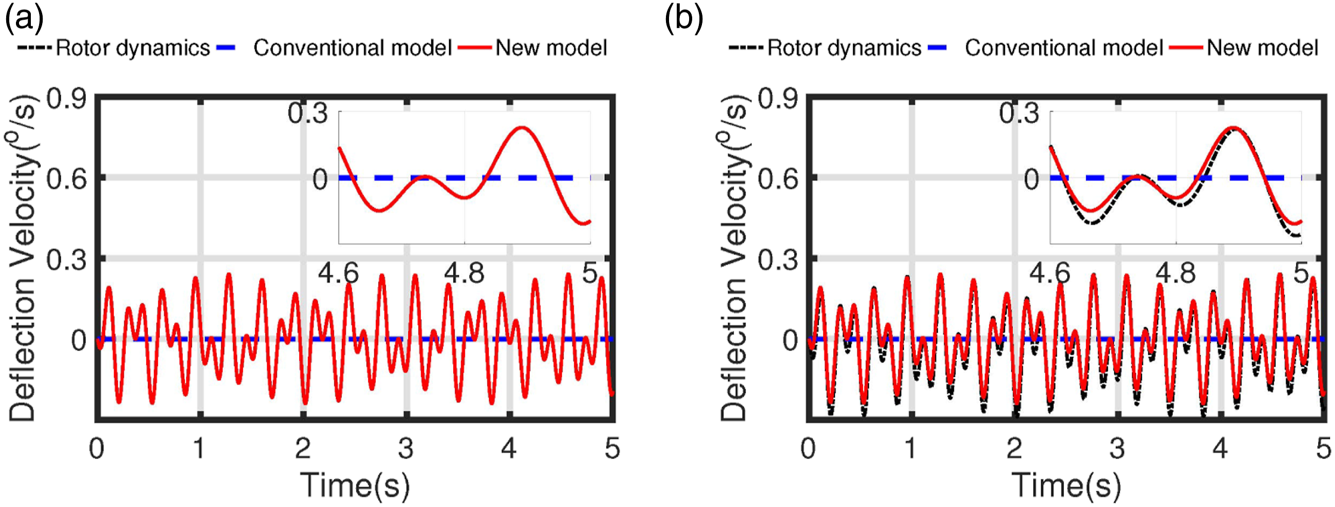
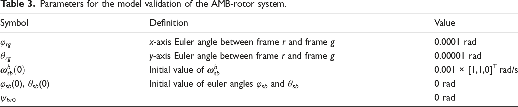
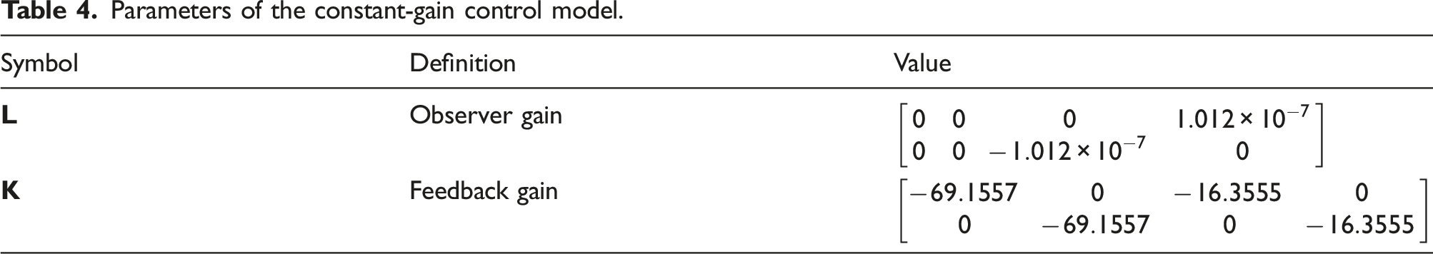
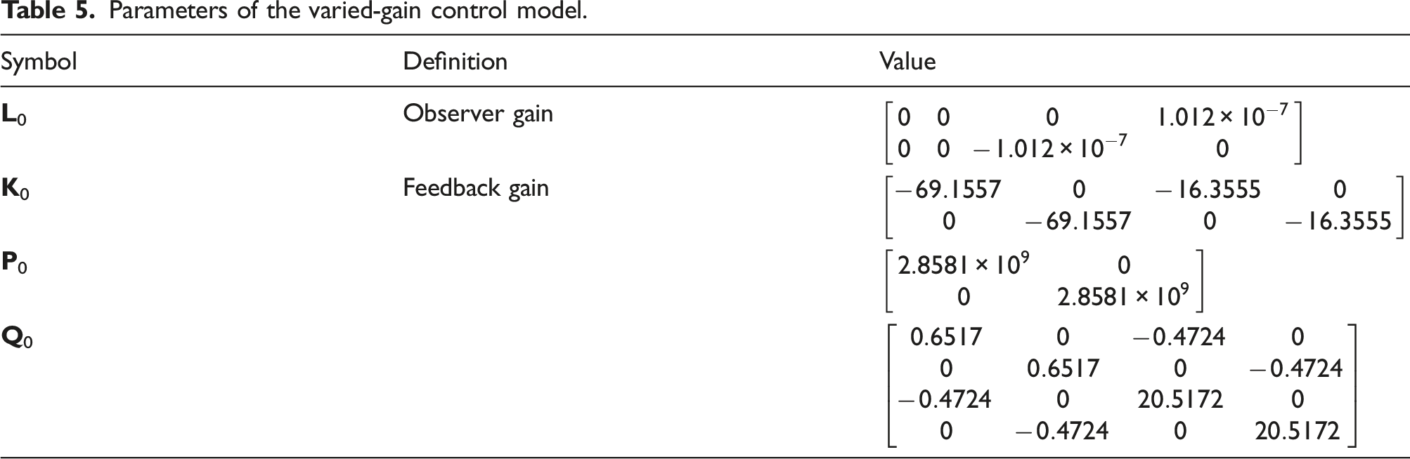
The speed curve in Figure 6 is chosen as the reference rotating speed, and the control parameters of the constant-gain model are obtained by solving the LMIs in (7) and (12) when the rotating speed Ω = 3500 rpm. The initial rotating speed Ω0 for the varied-gain model is also selected when the rotating speed is 3500 rpm. The derivation is computed by a continuous differentiator, and the parameters of the AMB, the constant-gain model, and the varied-gain model are listed in Table 3, Table 4, and Table 5, respectively. The gains The reference rotating speed of the MSMW. Parameters for the model validation of the AMB-rotor system. Parameters of the constant-gain control model. Parameters of the varied-gain control model.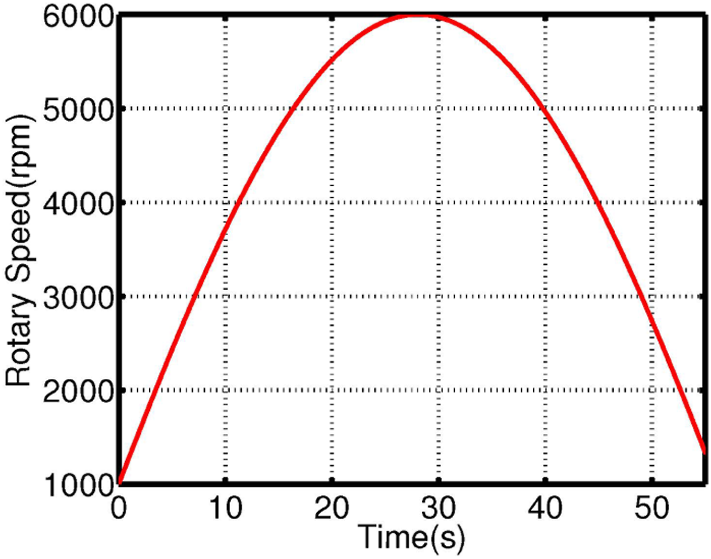
The comparisons between the cross-feedback method and the proposed varied-gain method are illustrated in Figure 7 and Figure 8. Figure 7(a) shows the estimated disturbance torque of the varied-gain control model. The black dashed lines represent the actual disturbance, and the red solid lines indicate the estimated disturbance of the proposed method. The estimated value converges to the actual value, and the convergence time is approximately 8 s. The error between the estimated value and the actual value is about 0.001 Nm, so the proposed varied-gain control method could timely and accurately estimate the disturbance torques acting on the MSMW suffering the synchronous disturbances. In addition, the power spectrum density (PSD) values of the disturbance torques are plotted in Figure 7(b) because the MSMW is affected by the synchronous disturbances with the high frequency components. The PSD of the estimated disturbance is nearly consistent with the actual disturbance after the observer reaches the steady state. These results indicate that the observation error model is stable when the rotating speed varies. The model comparison of the MSMW considering the base motion: (a) the deflection velocity of the rotor shaft without base motion and (b) the deflection velocity of the rotor shaft with base motion. The comparison of the MSMW with different control models: (a) the dynamic response of the MSMW with different control models and (b) the PSD of the MSMW with different control models.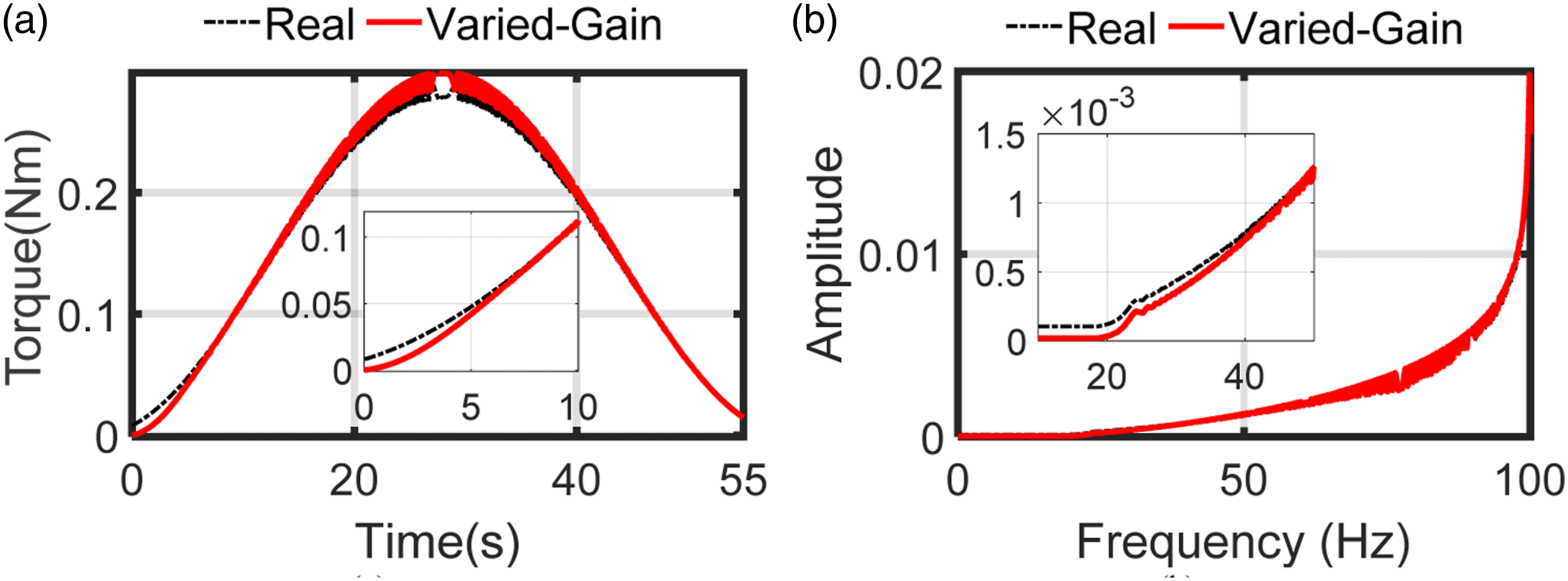
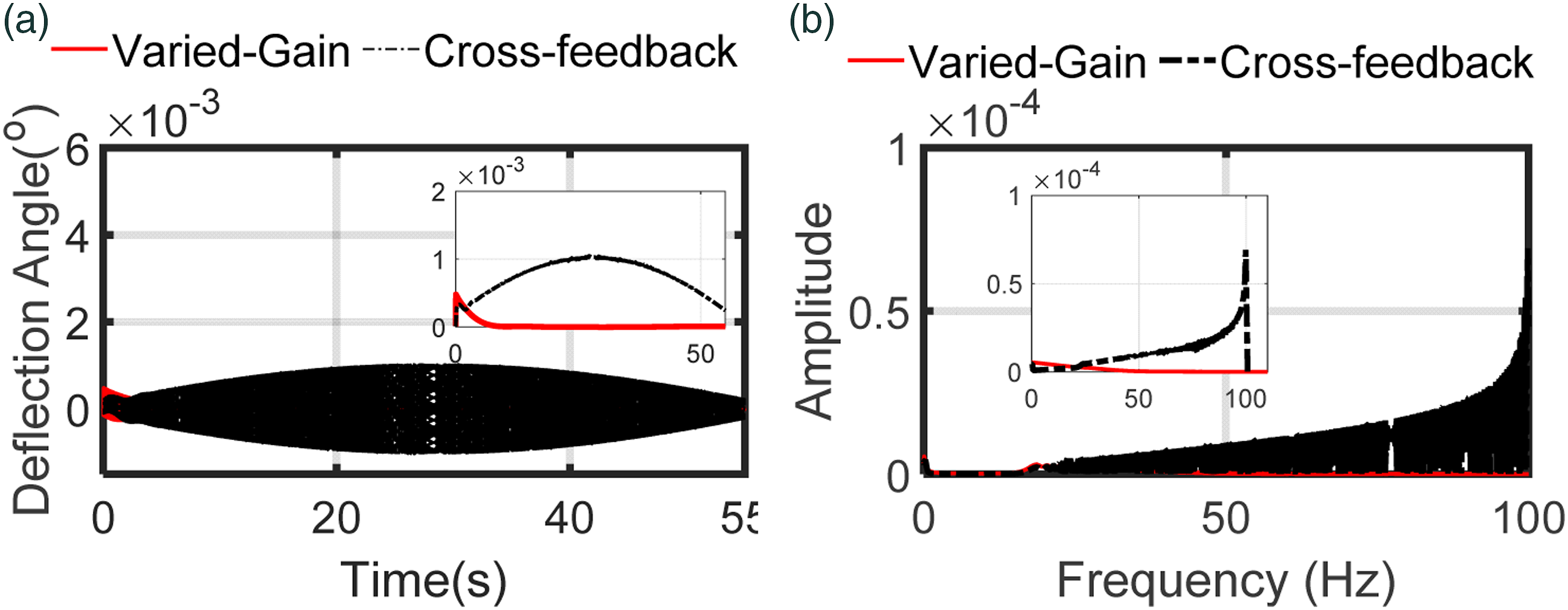
The deflection angles using two control models are shown in Figure 8, and the deflection angle using the proposed varied-gain model is shown by the red solid line, and the deflection angle of the cross-feedback model is marked by the black dashed line. In Figure 8(a), the deflection angles are stable and varying with the rotating speed from 1000 rpm to 6000 rpm. The maximum deflection angle using the cross-feedback control model is about 0.001°, and the maximum value using the proposed varied-gain model is reduced to 0.0005°. Moreover, the PSD of the deflection angles are plotted in Figure 8(b), and the deflection angle yields synchronous vibration which increases with increased rotating speed. The vibration amplitude of the deflection angle using the varied-gain model is smaller than the cross-feedback method, so the synchronous vibration with the varying rotating frequency could be effectively suppressed by the proposed varied-gain control model. Thus, the deflection angle is significantly suppressed by the proposed varied-gain control method.
Furthermore, the comparison between the constant-gain model and the proposed varied-gain model is conducted. The parameters of the constant-gain method were acquired by solving the LMIs in (7) and (12) for a constant rotating speed Ω. The estimated disturbance of two models are shown in Figure 9, and the black dashed line is the actual disturbance, and the red solid line and the blue dash-dotted line represent the disturbances estimated via the proposed varied-gain model and the constant-gain model, respectively. The estimated disturbance of the MSMW using different control models: (a) the disturbance torques in imposing on the MSMW and (b) the PSD of the disturbance torques.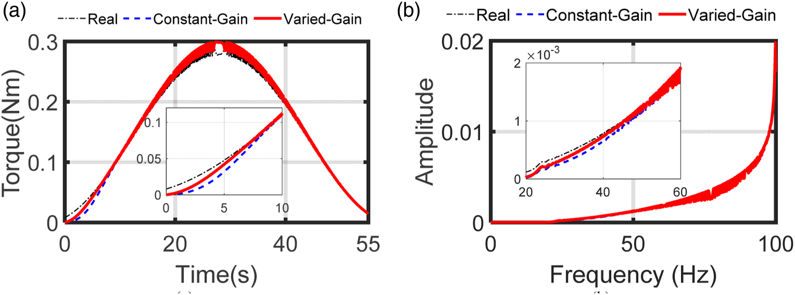
According to the results in Figure 9(a), the two control models could stably estimate the synchronous disturbance. Because the observer of the constant-gain model has to maintain the stability when the rotating speed varies, the control performances are weakened. The convergence time of the constant-gain control model is about 10 s, which is longer than the convergence time of the proposed varied-gain model.
In Figure 10, the two methods realize stable control of the deflection angle. As illustrated in Figure 10(a), the deflection angle of the proposed varied-gain model (red line) converges faster than the constant-gain model (blue line), and the angle precision of the proposed model is better than that of the constant-gain model. The control performances of the MSMW using the constant-gain model and the proposed varied-gain model: (a) the deflection angles of the MSMW and (b) the PSD of the deflection angles.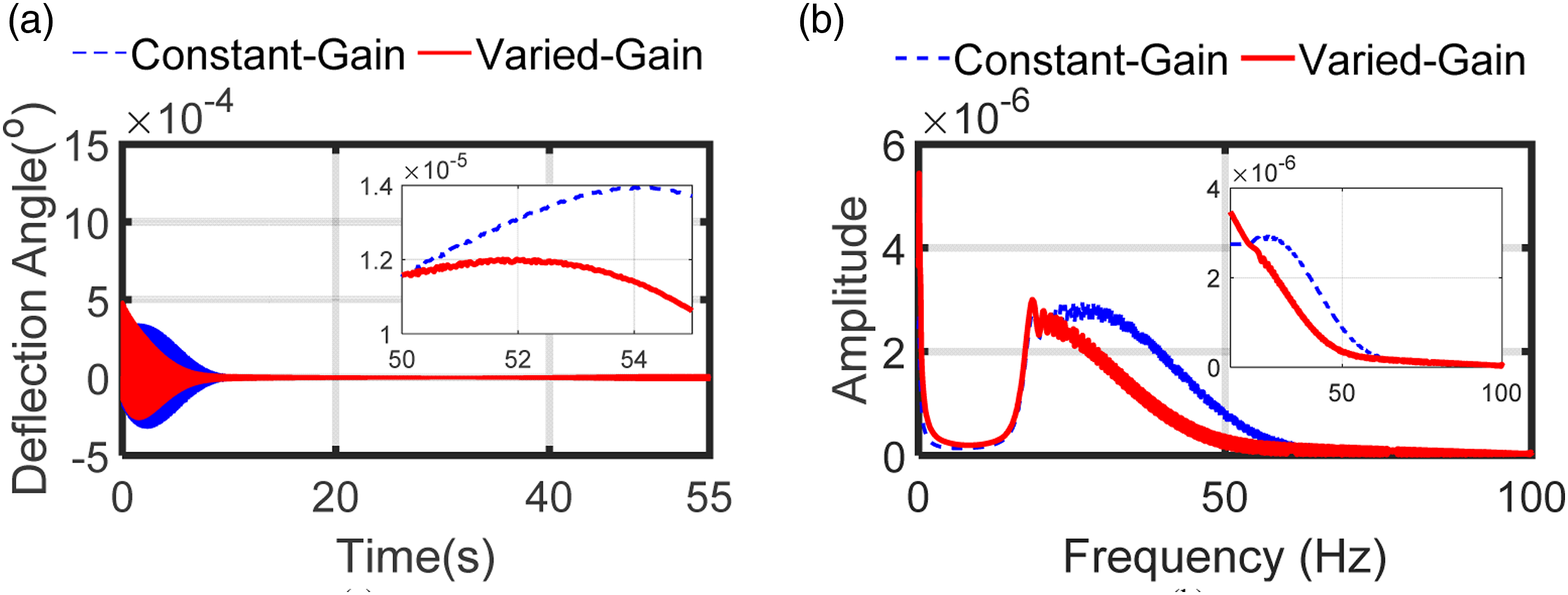
5. Experiments
The laboratory experiments are conducted to further validate the effectiveness of the proposed varied-gain model, and the experimental setup is shown in Figure 11. The eddy current sensor is used to measure dynamic displacements of the rotor shaft, and the sampling rate of the sensor was set to 5 kHz. A digital signal processor (DSP) TMS320C6701 with a 12-bit A/D converter is used in the implementation of the control algorithms. The pulse width modulation (PWM) amplifier is used to drive the AMB units to generate the magnetic forces. An oscilloscope is used to timely show and record the deflection angles. The experimental setup.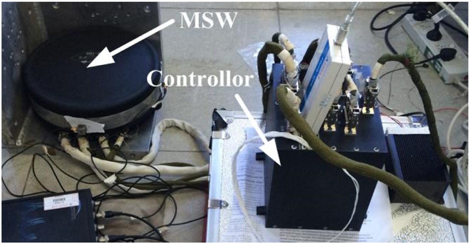
During the whole experiment, the control law is shifted from the cross-feedback model to the varied-gain model at 120 rpm, and the deflection angles during the experiment are illustrated in Figure 12. The peak–peak value of the deflection angle is reduced from 0.008° to 0.002° when the control model is switched from the cross-feedback model to the varied-gain model, and the relative reduction is about 75%. The deflection angles using different control models (experiment): (a) the deflection angle around the x-axis and (b) the deflection angle around the y-axis.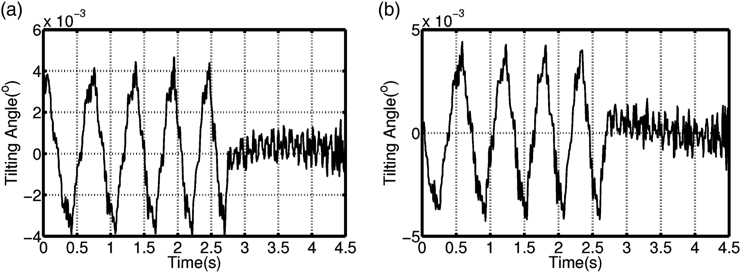
The deflection angles at 1,000 rpm are shown in Figure 13, where the dashed blue line is the deflection angle of the cross-feedback model, and the dash-dotted red line indicates the deflection angle of the proposed varied-gain model. In Figure 13(b), the PSD of the dynamic displacement using the cross-feedback model at synchronous frequency is 1.668 × 10⁻³ deg, the PSD of the dynamic displacement with the proposed varied-gain model at synchronous frequency is 3.31 × 10⁻⁴ deg, and it is approximately 28.34% of the amplitude of the cross-feedback method. Therefore, the proposed varied-gain model could suppress the synchronous vibration of the deflection angles at different rotating speeds. The comparison of deflection angles using cross-feedback and varied-gain models at 1000 rpm: (a) the deflection angles using the cross-feedback and the varied-gain models and (b) the PSD of the deflection angles using the cross-feedback and the varied-gain models.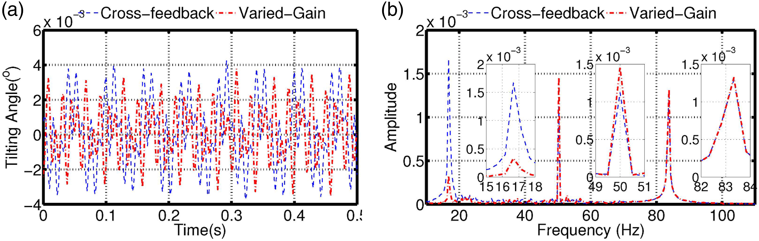
6. Conclusion
To suppress the synchronous disturbance of the MSMW with varied rotating speed, an observer-based varied-gain control model using the disturbance model is designed in this article. The gains of the observer model and controller model are obtained by solving a set of LMIs, and a gain-scheduled model is designed to maintain the stabilities of the observer and controller models. The simulations and experiments are performed to demonstrate the effectiveness of the proposed varied-gain model, and the results show that the proposed varied-gain model is an effective method of attenuating the synchronous disturbances of the MSMW. There are two distinct benefits to using the proposed varied-gain model: (1) attenuation of the synchronous disturbances varying with rotating speed and (2) stability and performance maintenance despite rotating speed fluctuation.
Footnotes
Declaration of conflicting interests
The author(s) declared no potential conflicts of interest with respect to the research, authorship, and/or publication of this article.
Funding
The author(s) disclosed receipt of the following financial support for the research, authorship, and/or publication of this article: This work was supported in part by the National Natural Science Foundation of China under Grant 62173039 and Grant 61603019.