
Abstract
Large lightweight slender links mounted on mobile robots enlarge their workspace. This work presents one of these robots that has been endowed with 4 legs to improve its static stability—which is put at risk by the large link—and help in the positioning of the link. The efficiency of this system depends on its accuracy in positioning and orientating the end-effector placed at the tip of the link, which is compromised by vibrations that appear in the link during the movement and permanent deflections caused by gravity. A relatively simple control scheme that combines a feedback control of the pose of the mobile platform with a feedforward term that orientates the link is proposed. It uses three legs as actuators; and feeds back measurements of the extensions of the three legs and the orientation of the platform given by an inertial sensor placed in the upper part of the mobile platform. Based on the flatness property of a simplified dynamic model of the link, its dynamics can be easily inverted, being used to implement the proposed feedforward term. Since such feedforward term is used, extra sensors to measure the deflection of the link are not needed, and since the legs are used to move the link, extra actuators mounted on the link are neither needed. All this allows us to reduce the weight and the volume of the payload carried by the mobile platform. Results obtained through a finite elements software and experimentation of the real prototype show the good performance attained with the proposed control strategy.
1. Introduction
Very large slender lightweight mechanical structures are finding application in many industrial and scientific applications. They have the advantages of having reduced cost, larger workspace, better transportability, reduced energy consumption, and a safer operation due to its lower weight and inertia. However, it is difficult to accurately position these structures because they vibrate when they are moved. Thence, many dynamics models, sensory systems, and control systems have been developed in the last years to deal with the problem of achieving precise positioning of flexible robots or structures (see Dwivedy and Eberhard (2006) and Kiang et al. (2015)).
Besides, mobile robots have aroused considerable attention. They can operate in environments that are hazardous or inaccessible to humans. In many cases, they perform manipulation or inspection tasks in unattainable places. Then, large structures are mounted on these mobile platforms (see the survey on mobile robots Bloch et al. (2003)). Some applications are demining (Freese et al. (2007)) or aircraft painting (Morelli et al. (2018)). These robots are vulnerable to rollover or tip over, especially when they work on uneven or sloped terrains, or when they exert large forces or move heavy payloads. Outriggers have been used as stabilizers in mobile cranes, for example, Jeng et al. (2010) and Romanello (2018), and mobile robotics applications, for example, Ohashi et al. (2016), to level these systems and increase their safety.
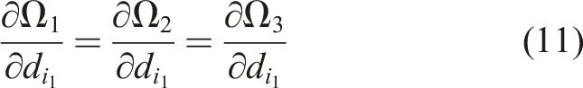
The objective of this article is to control the pose (position coordinates, x t − y t − z t , and pitch and yaw orientation angles, ϕ t − θ t ) of an end effector placed at the tip of a 2 m long link mounted on a mobile platform that has 4 wheels and 4 actuated mechanical legs. The wheeled subsystem is used to transport such large link. The 4 actuated legs is the novelty of our mechanism compared with previous designs. These legs are used to enlarge the stability polygon of the robot, as the outriggers do, and help to position and orientate the end effector placed at the tip of the link by changing the posture of the base of the platform.
Then 8 actuators are available (4 wheels and 4 legs). The 4 wheels are used to control the coordinates x t , y t , and θ t , and three legs are used to control the remaining coordinates z t and ϕ t . The 4th leg is used to form a stability polygon of 4 vertices. The kinematics, end effector pose control, and robot workspace assuming that a rigid link has been mounted were given in our previous work Feliu-Talegon et al. (2018).
A rigid 2 m long link cannot be mounted on our platform because its huge weight impedes its transportation. Then a slender lightweight flexible link has been mounted. The accuracy in positioning and orientating its end effector depends on eliminating vibrations produced during the movement and permanent deflections caused by gravity. Improving such accuracy is challenging because this system has high dimension non-linear dynamics, and vibration modes of high order can be excited that can unstabilise the closed-loop system (spillover effect).
Examples of trajectories that prevent the apparition of vibrations in mobile manipulators with flexible links and joints are Ghariblu and Korayem (2006), which developed a computational algorithm that obtained optimal trajectories of a linearized dynamical model with linearized constraints; and Almasi et al. (2014), which investigated optimal path planning using the Pontryagins minimum principle.
Feedforward strategies have been applied to flexible arms. Önsay and Akay (1991) used a Bang–bang control to drive the arm from an initial to a final position in the minimum time with the least residual vibration. Filtering techniques have also been employed like low-pass filters, band-stop filters, and notch filters, for example, Tzes and Yurkovich (1989), Wu et al. (2015). Another strategy is the input shaping which convolves a desired command with a sequence of impulses, for example, Pereira et al. (2012), Yavuz et al. (2012). However, this method is tailored only for linear systems. It was also used in nonlinear system, but some nonlinear terms were neglected, for example, Feliu-Talegón et al. (2014).
Closed-loop control of the vibration has also been implemented by feeding back measurements of sensors installed on the manipulator. For example, a robust control of an inverted elastic pendulum mounted on a mobile cart was proposed in Gorade and Kurode (2015) using a sliding mode controller. The control of a linear-motor-driven flexible beam system with arbitrary number of vibration modes and actuator saturation was addressed in Lu et al. (2013). Finally, we mention a 2-link flexible arm with a payload at its tip, that is carried by a translational stage. It has two vibration modes and was controlled by feeding back the angle of the joint between the 2 links (Wu et al. (2018)).
Wheel movements cannot be used to remove link vibrations because they have uncontrolled slipping which affects the precision of the movement, and a low frequency response bandwidth which prevents their use in the effective cancellation of link vibrations. In the previous references, vibration was removed using linear motor drives that were also used to displace the robot, or rotational drives installed on the manipulator. Then we propose to use 3 legs to achieve the following four objectives: (1) reach the desired z t , (2) reach the desired tip orientation θ t , ϕ t , (3) remove the residual vibrations in θ t and ϕ t , and (4) compensate the effect of gravity deflection on coordinate z t by correcting ϕ t .
To the best of the authors’ knowledge, this is the first time that actuated legs are used in a mobile robot to autonomously level the system and, simultaneously, help in positioning and orientating the end effector placed at the tip of a large flexible link while damping the vibrations of its structure. By using 3 legs as actuators, and feeding back measurements of their extensions and the platform orientation, θ, ϕ, provided by an inertial sensor placed in the upper part of the mobile platform, the posture of the mobile platform is controlled.
A control system is proposed to accomplish the four previous objectives, that combines a feedback control of the pose of the mobile platform with a feedforward control that orientates the link. It addresses the control of a nonlinear highly coupled system with 10 states (2 for each leg plus 4 states for the vibrations of the link in two dimensions), 3 input signals, and 5 outputs by using a relatively simple scheme. Addition of specific actuators or sensors to remove the link vibration is not required, which allows us to reduce the weight and the volume of the payload carried by the mobile platform. Moreover, spillover effects are avoided since feedforward techniques only modify the reference signals. Our novel control system is different from the mentioned ones (and others) because 1. The trajectory is divided into 2 stretches: a straight line translation of the link in the direction of the link orientation, to the target position, that avoids the appearance of vibrations; and a rotation around the base of the link, which is maintained fixed, that induces a vibration which will be prevented by our feedforward term. This simplifies the generation of movements free of vibrations because, in the first stretch, the link is moved as if it were rigid and, in the second stretch, the vibration of the relatively simple system is avoided using a feedforward term. Trajectories of other works that avoid vibrations are made of a single stretch whose calculation is more involved than ours because the dynamics of a link under simultaneous translation and rotation—required either to be inverted in a feedforward term or to numerically generate the trajectory—are much more complicated than the dynamic model used in our second stretch. Then, our approach allows the real time generation of vibration-free movements while others, when dealing with similar nonlinear systems, do not. 2. A single vibration mode is assumed for our link. The resulting nonlinear dynamic model has the flatness property, unlike the dynamics of other similar systems already mentioned. 3. The flatness property allows us to design a feedforward controller based on the inversion of the link dynamics which is different from others because (a) it is nonlinear while most of the feedforward techniques that cancel vibrations are linear and are suited for linear systems; and (b) the exact inversion of the link dynamics is carried out, which usually cannot be done in other nonlinear flexible systems that are not flat.
The remaining of this article is organized as follows. Section 2 describes the experimental platform. Section 3 proposes a dynamic model. Section 4 develops the new control strategy. In Section 5, simulated results are obtained using a FEM software, and experimental results are shown. Some conclusions are presented in Section 6.
2. Mobile robot prototype
2.1. Mechanical design
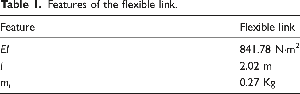
The system consists of a very large lightweight structure mounted on a mobile platform. The very large lightweight structure is a link made of a composite material that is free at its tip and is clamped to the platform at its base. A pan tilt zoom camera is placed at the free end of the link for inspection tasks. The mechanism built at the base of the camera allows to adjust the camera to the end of the structure and change remotely the directional and zoom control (see Figure 1(a)). Table 1 shows the features of the flexible link where EI is the link flexural rigidity, l is the length of the link, and m
l
is its mass. On the other hand, the platform is a mobile base with rectangular shape, four actuated legs and four wheels (see Figure 1). The dimensions of the platform can be found in Feliu-Talegon et al. (2018). (a) Real prototype, (b) Hardware components. Features of the flexible link.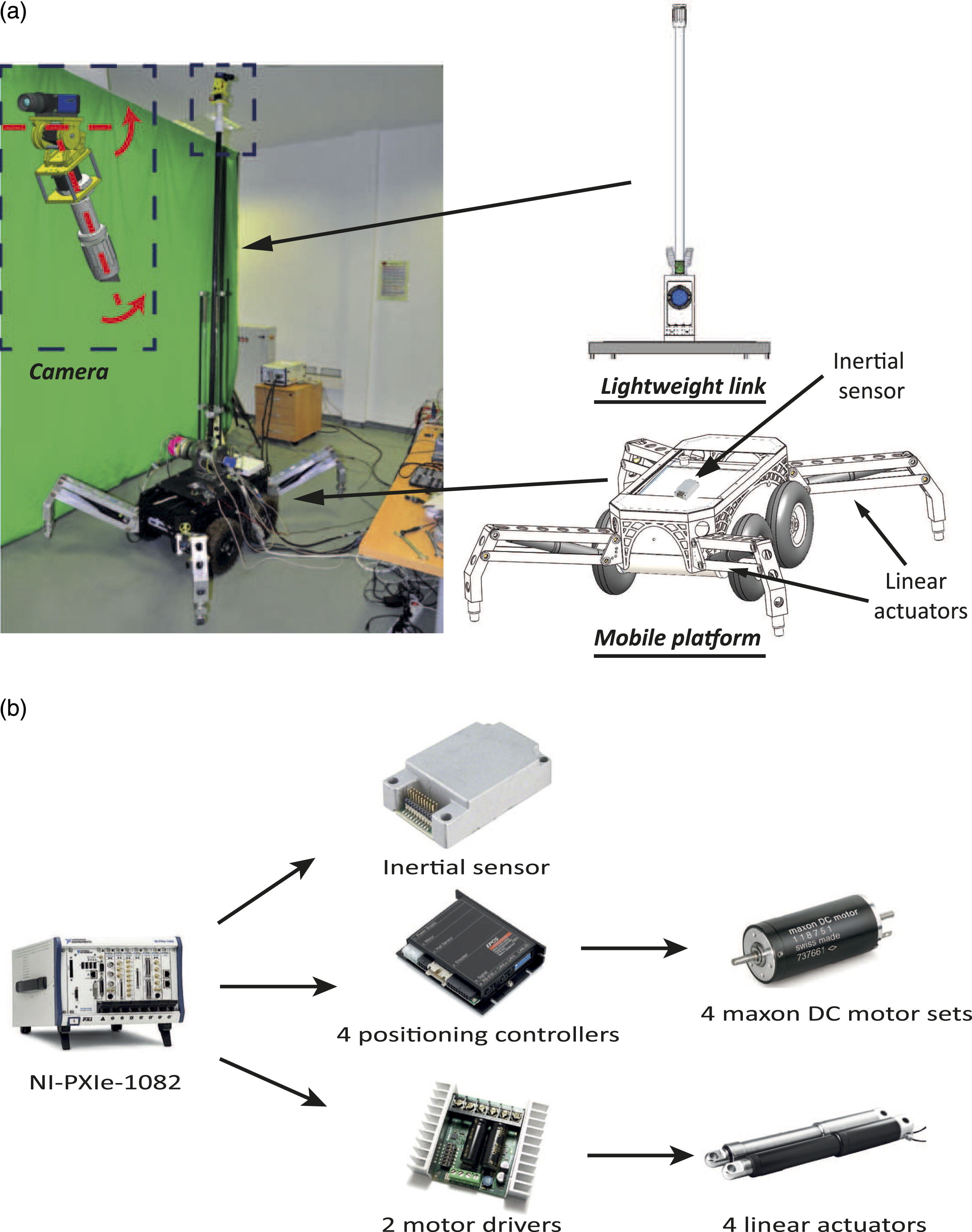
The system can operate in 2 different configurations:
2.2. Hardware components
This section describes the control architecture of the robot, the sensory system, and the actuation of the system for the second configuration of the platform. The control architecture of the system uses a NI-PXIe-1082 which is a real-time high-performance embedded controller. The actuation and acquisition system runs LabVIEW Real-Time for analysis and control. The robot has four linear actuators to change the position of the legs of the system. Each actuator has an encoder that measures its displacement. The system has two driver amplifiers to control the four actuators with analog voltages independently, and an inertial sensor placed on the top of the mobile platform that measures the orientation of the base. Moreover, the platform has four limit switches to perceive when each leg is in contact with the ground. The real prototype and its components are represented in Figure 1.
3. Modeling of the components of the robot
3.1. Linear actuator model
The dynamics of DC motors can be described by a second-order equation. A linear actuator is a type of actuator that converts the continuous rotation of a DC motor into a linear movement. Then, its dynamics can be expressed as follows
3.2. Kinematic model of the four-wheeled platform
The kinematics of the robot using legs (second configuration) is presented here. The orientation of the frame is defined by its roll (ϕ
i
), pitch (θ
i
), and yaw (ψ
i
) angles about fixed frames. First, we define the fixed frame {A}, whose Z axis is parallel to the force of gravity, but in the opposite direction. Also, we define the frame related to the mobile base as {F}. This is an inertial frame whose Z axis is perpendicular to the upper part of the base of the truck. The forward kinematics defines the relation among the posture and orientation of the base of the platform and the position of the linear actuators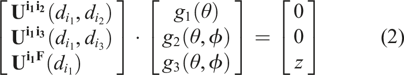
3.3. Model of the flexible link robot with two degrees of freedom
The dynamics of a flexible beam has infinite vibration modes. Since the amplitudes of the vibration modes decrease as their frequencies increase, these dynamics can be truncated taking into account only the lower vibration modes. The particular case of a flexible link with a payload mass much bigger than the mass of the link verifies that (1) only one vibration mode is important if we consider a lumped payload mass without rotational inertia and (2) the dynamic model is relatively simple (e.g., see Feliu and Ramos (2005) for a link moving in an horizontal plane).
Here, we develop a dynamic model of a flexible link mounted on a mobile platform assuming that the position of its base is fixed and only changes in the orientation are produced. The following assumptions are made • Uniform elasticity coefficient E and link cross section I. Then we define the elasticity constant c = 3EI/l. • The mass of the link is negligible. • The payload placed at the tip of the link is a lumped mass m
t
, that is, the rotational inertia is negligible. • The links deflection is small compared to its length (lower than 10%).
The aforementioned assumptions are often used to model flexible robots in which the mass of the tip payload is higher than the mass of the link, for example, Feliu et al. (1992), Feliu-Talegon et al. (2019). In particular, Assumptions 2 and 3 were checked prior to the obtention of the dynamic model and the control system: the frequency response of the link was obtained by simulation using a FEM software and by direct experimentation on the prototype, and we verified that only one vibration mode appeared, whose frequency value matched very well with the frequency value provided by the dynamic model obtained under the massless link assumption combined with the other assumptions.
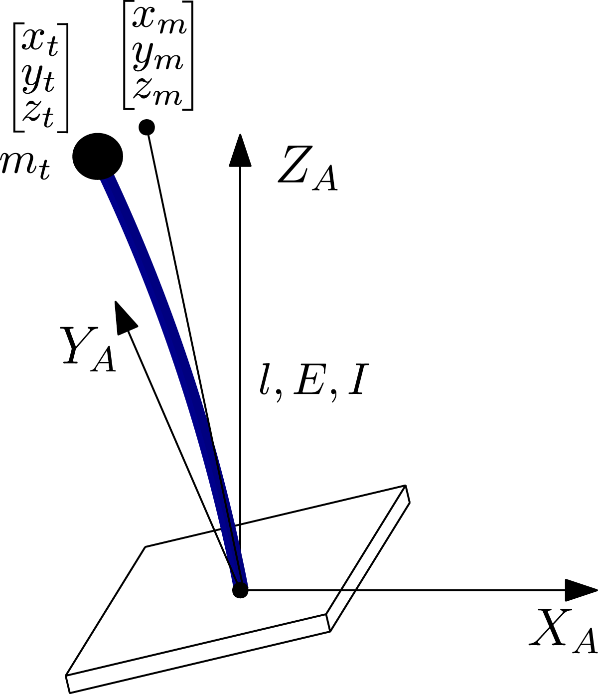
The orientation of the platform is described by the rotation matrix R(ϕ, θ, ψ) with respect to the fixed frame {A}. There is no rotation about the Z
A
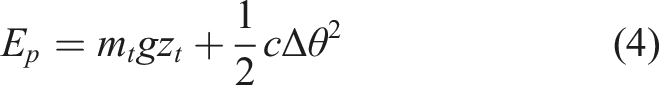
axis because the movement of the actuated legs do not produce a rotation in the Z axis. Figure 2 shows a scheme of the system. The kinetic energy, E
k
, and the potential energy, E
p
, of the link are Scheme of the flexible link mounted on a base.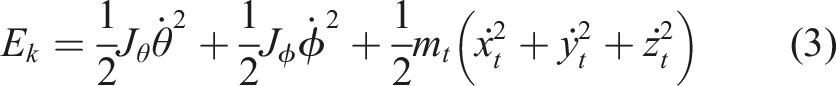
3.4. Complete model of the mobile flexible robot
Finally, the complete model of the robot is described by combining the submodels developed for each part of the robot (see Figure 3). The inputs of the system are the voltages applied to the four linear actuators of the legs whereas three components of the end-effector pose Scheme of the whole system.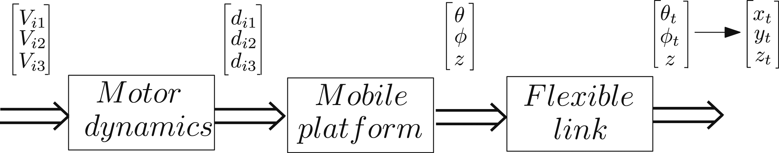
4. Control strategy
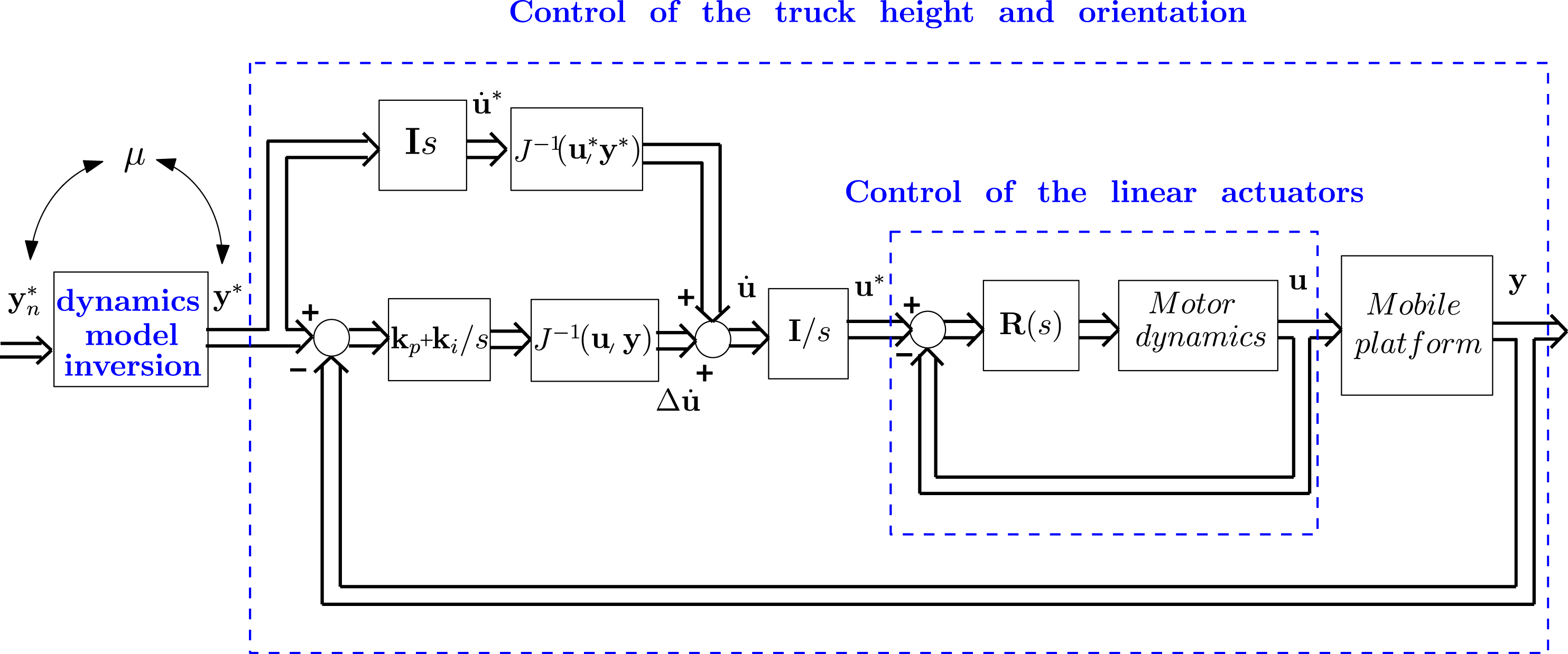
This section presents a control scheme to position the end-effector of the robot. It combines the inversion of the dynamics of the flexible link (open loop control technique) with a closed-loop control of the inclination and posture of the platform. In our control system 1. The inputs are the voltages 2. The positions of the linear actuators 3. The output variables to be controlled are
The proposed methodology performs the following steps (1) design controllers to achieve a fast closed-loop response of the linear actuators and remove the friction effects, (2) design an outer-loop control of the truck height and orientation, and (3) design the feedforward term that inverts the dynamics of the flexible link in order to accurately position the end-effector of the robot.
Assume that the mobile platform has been placed in a pose (x, y, z, θ, ϕ) that allows the tip to reach its desired pose (x
t
, y
t
, z
t
, θ
t
, ϕ
t
) by extending its legs. This legs extension implies a 3D displacement with pitch and yaw rotations of the link. Its dynamics model has 5 inputs (x, y, z, θ, ϕ), corresponding to the link base movement, and 5 outputs (x
t
, y
t
, z
t
, θ
t
, ϕ
t
), corresponding to the tip pose. This model is complicate and cannot be used to implement efficient feedforward terms. We propose a trajectory composed of two stretches that simplify the models to be inverted. The first stretch is a straight line in the direction of the link that places its base in the adequate position without producing vibrations. Then a feedforward term is not needed. The second stretch is a rotation of the link around its base to obtain the desired orientation. This produces vibrations to be compensated by the feedforward term. Since the link base remains quiet, simple dynamics relate the base rotation (θ, ϕ) with the tip orientation (θ
t
, ϕ
t
) that can be efficiently inverted in real time to implement our new nonlinear feedforward term. It removes link vibrations and compensates the deflection caused by gravity. However, this inversion is not exact because the rigid dynamics of the set legs-platform are not included in the model to be inverted. Then, the following simplifying assumptions are made in the design of our control system: 1. During the first stretch, link base deviations to the straight line are negligible. 2. During the second stretch, the base of the link remains approximately motionless. 3. The link dynamics are approximated by the dynamics of a massless link with a payload at its tip. 4. Link dynamics verify the flatness property, which implies that the inputs can be expressed as functions of the outputs and their time derivatives Sira-Ramirez and Agrawal (2018). 5. Our feedforward term performs perfect cancellation of the link dynamics if the closed-loop dynamics of the legs-platform set is one. Since this cannot be achieved, we assume that the bandwidth of the frequency response of this set is significantly higher than the link vibration frequency. This assumption yields a good compensation of vibration and deflection.
The components of the control system are described next.
4.1. Linear actuator control
The positions of the linear actuators are fedback and controllers are designed using model (1) to achieve very good trajectory tracking and robustness to motor frictions and parameter uncertainties. PI controllers of the form
4.2. Combined feedforward-feedback control of the platform height and orientation
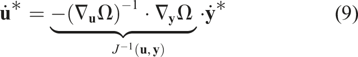
We propose a new approach to control the orientation of the platform (θ, ϕ) and the height of its center of mass (z) using the legs moved by the actuators with the previous controllers. This control strategy combines the inversion of the forward kinematics (feedforward term) and a closed-loop control applied to its Jacobian model. The orientation given by the inertial sensor is fedback to reduce the steady-state error in the orientation of the platform prompted by little inaccuracies in the model.
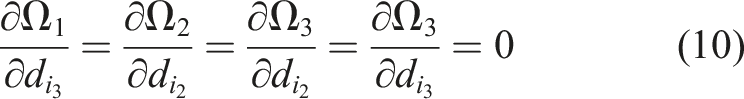
Differential kinematics: As it was mentioned previously, the system has three inputs, the position of three linear actuators 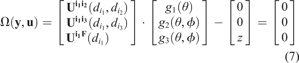


The tracking error is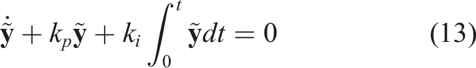
Upon combining equation (8), equation (12), and (13), the control law is obtained

4.3. Vibration control of the end-effector of the robot
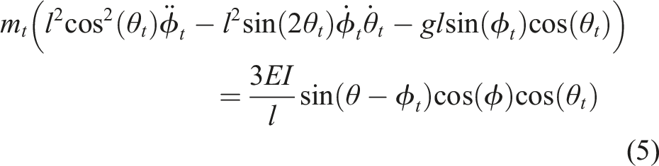
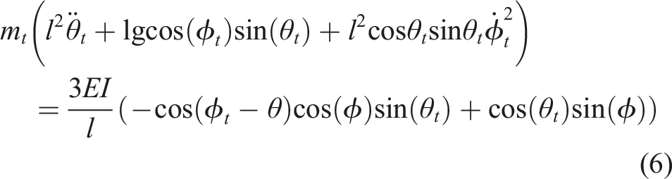
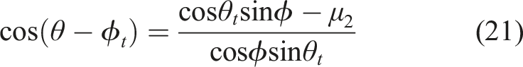
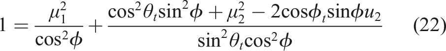
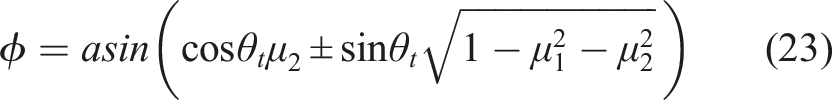
A straight line of the center of frame {F} is first commanded in the direction of the orientation of the link to achieve the desired height. Since inertial forces prompted during this movement have the same direction as the link and we assume that the link cannot suffer compression, the vibration induced by this displacement is zero. Subsequently, the desired orientation is achieved in a rotation around the fixed center of frame {F} by using the feedforward term that inverts the simplified model (5), (6). Next, we prove the flatness relationship in this model.
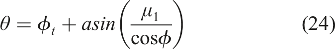
Let us define the fictitious inputs μ1 and μ2 as

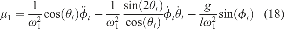
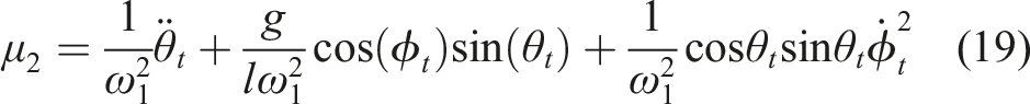
Upon inverting equation (16) and (17), we obtain that Control scheme.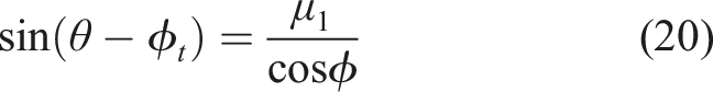
5. Simulated and experimental results
Simulations with the FEM software/Simulink and experiments with the prototype have been performed to verify the robustness and efficiency of the control technique. The poles of the closed-loop of the linear actuators are placed at p = −10 and the poles of the control law (13), (14) in − 5. The inversion of the dynamics of the flexible link is implemented using l = 2.02 m, a payload of 2 kg at the tip of the structure and the identified angular frequency of the link ω1 = 13 rad/s (see Table 1).
5.1. Simulated results
This section shows the simulated results of the system working in the Second Configuration with the proposed control technique, which is also compared with two well-known feedforward terms to cancel vibrations: input shaper (IS)s and prefilters that invert approximate linear dynamics (see Feliu-Talegon et al. (2016) and Feliu-Batlle et al. (2017), respectively), both applied in θ and ϕ. The transfer functions of the IS and the inversion of linear dynamics (Q), are defined by Simulated results without using the inversion of the dynamics of the flexible link. Simulated results using the proposed dynamics inversion and the other linear feedforward terms.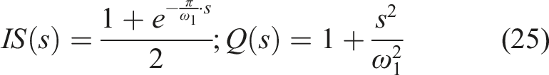
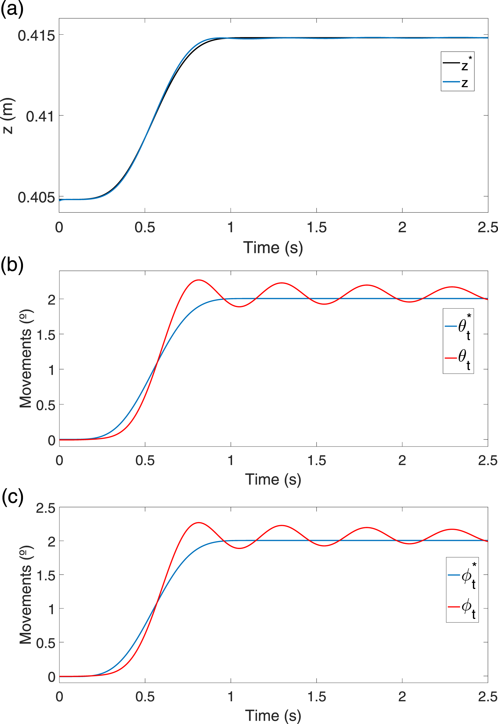
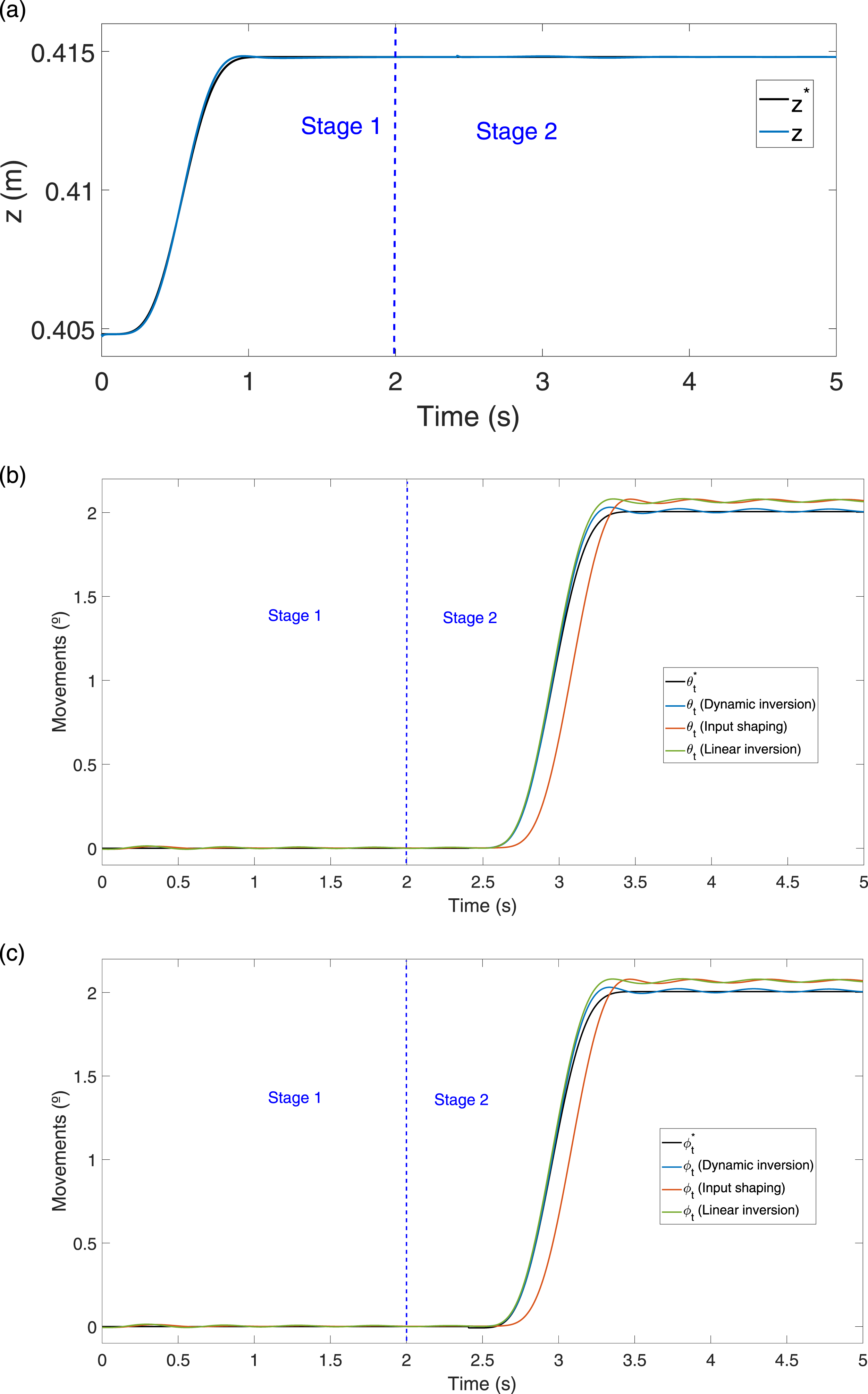
These plots show that the vibration of the system is removed effectively during the two stages. Moreover, it is shown that the effect of gravity can only be compensated with our proposed nonlinear feedforward term. Finally, Figure 7 shows the variation of the coordinates x, y, and z of the base of the link. Variation of the link base coordinates.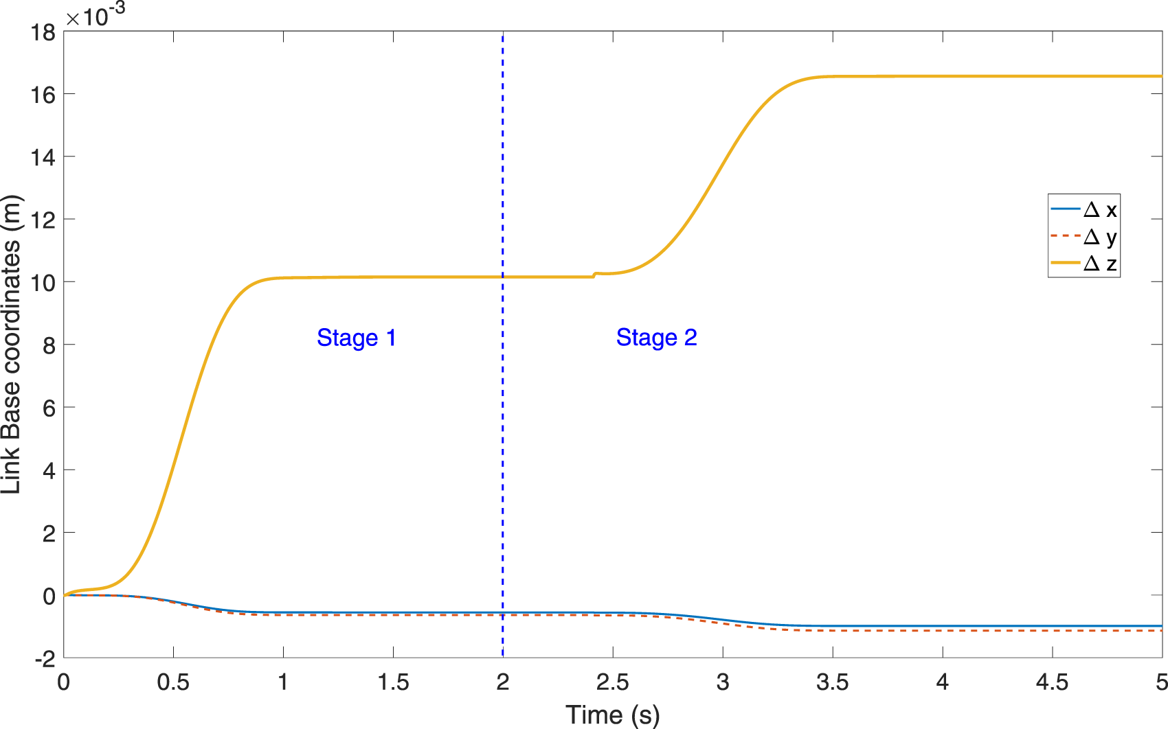
5.2. Experimental results
In this section, experiments with our prototype are carried out to verify the efficiency of the proposed control strategy in real-time implementations. To verify the results, a 3D tracking system is used as an external sensor with an accuracy of 0.05 mm. The inertial sensor was used to measure the components of the orientation of the platform (θ and ϕ), which are needed in the feedback of the outer closed-loop control. Its efficient implementation in the high-performance embedded controller NI-PXIe-1082 has allowed us to achieve a loop rate of 5 ms. The platform is placed on a flat ground (θ0 = 0° and ϕ0 = 0°).
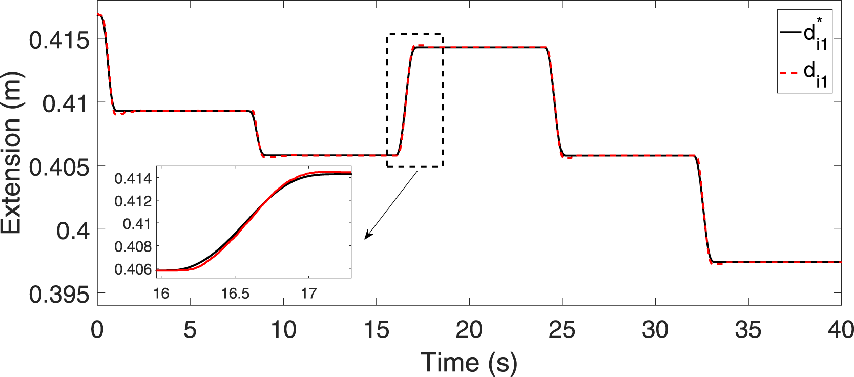
Several experiments are carried out using the proposed procedure. A different maneuver is performed in each case in the second stage of the procedure while the first stage is the same in the three cases (a) only component Experimental results using the proposed dynamics inversion.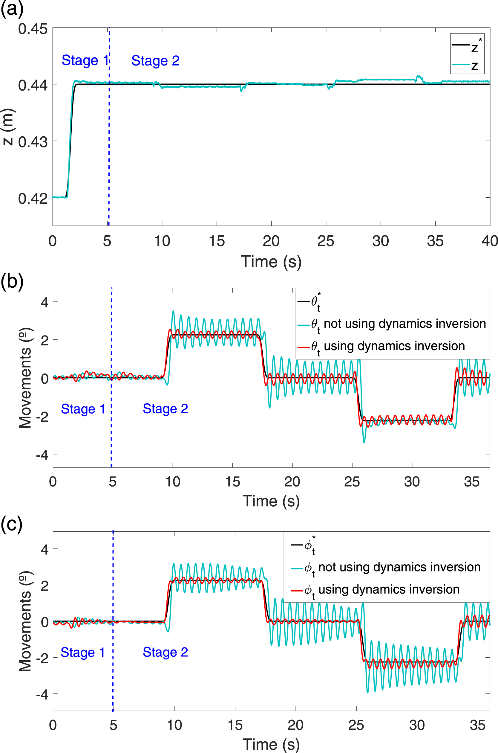
Figure 9 shows the results of the components of the orientation of the mobile platform while Figure 10 shows the reference and the position of a linear actuator. They show the good tracking performance of the linear actuators. These results show that if the dynamic inversion of the flexible link is used, the amplitude of the vibration drops to the fifth part of the amplitude obtained if the feedforward term based on the dynamic inversion is not used. Orientation of the platform, θ, ϕ, respectively. Trajectory tracking results of the linear actuators.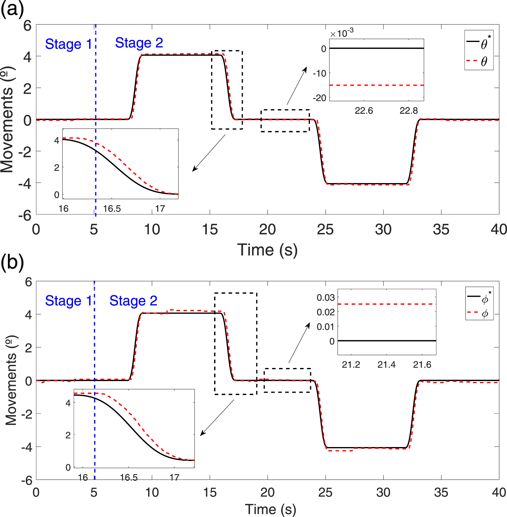
The results show the efficiency of the technique and the large improvement in the positioning of the end-effector of the robot without affecting the whole stability of the system since the flexible link control is based on an open-loop control technique.
Finally, the behavior of the closed-loop rigid dynamics of the set legs-platform has been analyzed to justify the good results obtained with in the inversion of the dynamics of the flexible link. Its equivalence response was experimentally obtained proving its linear behavior. The responses between the references of the components of the platform and their outputs were fitted obtaining the following equivalent transfer function Closed-loop rigid dynamics.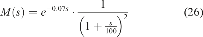
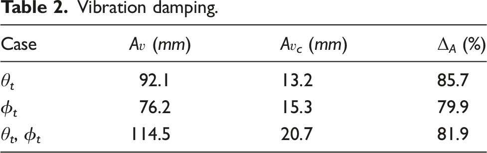
Vibration damping.
6. Discussion
Experiments and simulations validate the assumptions of our control system: • Figure 7 shows that the commanded vertical trajectory of the first stretch is followed by the base of the link with very small deviations in the x and y coordinates which confirms Assumption 1. Then vibrations are not induced, as Figure 6 a shows. • Figure 7 shows that, in the second stretch, coordinates x and y of the base of the link remain approximately constant but the coordinate z is slightly displaced, producing the small residual vibration of Figure 6, Figure 7, and Figure 8. Then Assumption 2 is only partially verified. • Responses of Figure 5, Figure 6, Figure 7, and Figure 8 show a single vibration mode whose frequency coincides with • Verification of Assumption 3 implies the flatness property. Its fulfillment allows the attenuation of the residual vibration shown in Table 2. • The frequency bandwidth of the closed-loop legs-platform set ω
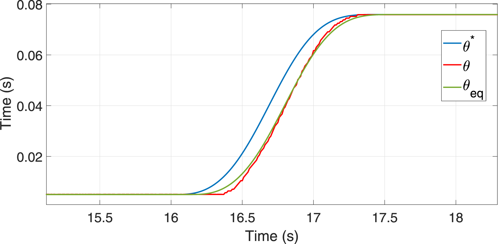
c
= 100 rad/s (obtained from (26)), is significantly higher than the link vibration frequency ω1 = 13 rad/s. Then Assumption 5 is verified and low amplitudes of the residual vibrations are obtained in simulations and experiments. Since our dynamics are time invariant, the delay of (26) is transmitted to the outputs, without altering the performance of our feedforward term.
Comparing the simulated results of the three feedforward terms, we can state that • Since the command is relatively slow, the nonlinear effects of the Coriolis and centripetal torques are irrelevant. Then the three terms yield a similar reduction of the vibration. • The IS shows a delayed response with respect to the other two feedforward terms of at least half a period of the oscillation. • The main difference among the 3 terms is the compensation of the gravity. Our approach is the only one that compensates the gravity because it includes its nonlinear effect in the dynamic model to be inverted. The other two terms yield high steady state errors that impede an accurate positioning.
7. Conclusion
We have controlled the position and orientation of a very large lightweight slender link mounted on a 4-legged platform by using 3 legs as actuators, and feeding back their extensions and the orientation measured by an inertial sensor placed on the mobile platform. Vibrations and the effect of the permanent deflection caused by gravity have been removed without having to use extra actuators and sensors on the link, which allows to reduce the weight and the volume of the payload carried by the mobile platform.
The design of our controller is based on 5 simplifying assumptions that yield a simple control system. Simulated and experimental results show the accuracy of these assumptions as well as the efficacy of our control system.
Footnotes
Declaration of conflicting interests
The author(s) declared no potential conflicts of interest with respect to the research, authorship, and/or publication of this article.
Funding
The author(s) disclosed receipt of the following financial support for the research, authorship, and/or publication of this article: This work was supported by the Grant PID2019-111278RB-C21 funded by MCIN/AEI/ 10.13039/501100011033.