
Abstract
The active vibration absorber represents an effective means to mitigate excessive vibrations in low-damping structures. Nevertheless, the dynamics of the actuators employed in such systems may negatively affect their performance and stability restricting their operational frequency range. This article presents an application of dynamics inversion techniques to the force control of electrodynamic proof-mass actuators employed as active vibration absorbers in lightweight pedestrian structures. The dynamics inversion approach is applied to enhance the classical direct velocity feedback scheme. Additionally, a novel method relying on dynamics inversion is presented: the Broadband Force Cancellation Algorithm. This procedure consists in estimating, in real-time, the equivalent force acting on the system to later apply it back to the structure with the opposed sign. The effectiveness of the proposed methods is assessed via numerical simulations carried over a realistic model of an existing lightweight footbridge and an electrodynamic proof-mass actuator. Two load cases are analyzed: a fixed swept-sine force and a walking load. Both cases account for the actuator-structure interaction. The human-structure interaction is considered in the latter scenario due to its importance when dealing with lightweight pedestrian structures. Simulation results demonstrate that the dynamics inversion techniques effectively cancel out actuator dynamics leading to an excellent tracking of the reference force output by the suggested or other vibration control algorithm. The proposed schemes are proved promising since they substantially outperform the widespread direct velocity feedback approach. In particular, the Broadband Force Cancellation Algorithm minimizes the action of the external forces within their estimation frequency range, thus being especially suited to tackle broadband excitations, important in lively pedestrian structures, whereas the velocity feedback methodology performs best at the structural resonant frequencies.
Keywords
1. Introduction
Inertial vibration absorbers have been extensively used to minimize vibration serviceability problems arising from the human-induced vibrations occurring in modern lightweight, low-damping structures such as footbridges or long-span floors.
A common approach to attenuate excessive vibrations consists in employing the (passive) tuned vibration absorber (TVA) (Elias and Matsagar, 2017; Yang et al., 2022). The TVA is tuned to a specific mode, circumstance which may lead to detuning problems when structural or TVA properties are time-varying. Techniques like multi-TVA (Casciati and Giuliano, 2009; Li et al., 2010; Bortoluzzi et al., 2015; Van Nimmen et al., 2016; Huang et al., 2020; Liu et al., 2021) or semiactive TVAs (Soria et al., 2017; Moutinho et al., 2018; Wang et al., 2021; Wang et al., 2021; Barrera-Vargas et al., 2022) have been proposed to overcome detuning issues.
The active vibration absorber (AVA) represents an effective alternative for vibration cancellation when a higher attenuation is required, more harmonics need to be damped simultaneously or the structural properties variation cannot be neglected. The main components of an AVA system are the actuator(s), the controller, and the sensor(s) (usually accelerometers). Several actuation technologies have been used in the context of human-induced vibrations. Some examples include fixed (Casado et al., 2013; Zhang and Ou, 2015; Mao and Huang, 2019) or deployable (Goorts et al., 2017; Goorts and Narasimhan, 2019) electromagnetic proof-mass actuators (PMAs), pneumatic actuators (Bleicher et al., 2011), and rotating-mass actuators (Terrill et al., 2020; Terrill and Starossek, 2022; Zhang et al., 2022).
A widespread group of AVA implementations focuses on a collocated actuator-sensor pair, leading to a single-input single-output (SISO) scheme. The most representative approach within this category is the direct velocity feedback (VF), which consists in exerting on the structure a damping force equal to the velocity of the point affected by a control gain. This algorithm holds the advantage of unconditional stability when the actuator and sensor dynamics are neglected and does not require a structural model, with the subsequent enhanced stability and robustness features (Wang et al., 2018; Díaz et al., 2021). Nonetheless, when the dynamics of the system are considered, the unconditional stability assumption no longer holds and a limit to the control gain exists. Several techniques have been proposed to increase the stability margin of VF including: the Acceleration Feedback Control (Diaz and Reynolds, 2010), the Inner Control Loop Approach (Díaz et al., 2012a), the Integral Resonant Control (Díaz et al., 2012b), the Virtual Mass Technique (Mao et al., 2020), the adaptive reduction of VF gain (Ahmadi, 2020), or the Independent Modal Space Phase-Lead VF Control (Xue et al., 2022). The SISO VF schemes may perform poorly when the target structure exhibits closely-spaced modes. The SISO limitations may be overcome by multiple-input-multiple-output (MIMO) strategies (Pereira et al., 2014; Camacho-Gómez et al., 2018; Wang et al., 2019).
Another group of AVA vibration control algorithms (VCAs) relies on a precise structure model to estimate the controlled modes states, upon which a gains matrix is applied to calculate the control command(s) (Hudson and Reynolds, 2012). Some examples of model-based controllers (MBC) include the Pole Placement method (Chang and Yu, 1998; Nyawako and Reynolds, 2015; Belotti et al., 2020), the Pole-Zero assignment (Richidei et al., 2022), the Modified Independent Modal Space Control (Etedali, 2017), the Linear Quadratic Regulator and the Linear Quadratic Gaussian Control (Goorts et al., 2017; Goorts and Narasimhan, 2019; Chang, 2020; Moradi et al., 2021), and the
In this work, the application of dynamics inversion (DI) techniques to the force control of a Commercial-Off-The-Shelf (COTS) electrodynamic PMA is presented. The DI constitutes a model-based, structured procedure whose aim is to find a PMA system inverse which, upon implementation in the controller, allows for an approximate cancellation of the PMA dynamics (Kwatny and Blankenship, 2000; Ramírez-Senent, et al., 2021). Consequently, a very accurate tracking of the target force output by any VCA is achieved. As to deal with the modeling errors and enhance overall stability and robustness, the DI is complemented with a parallel Three Variable Controller (TVC) (Yao et al., 2016). The proposed PMA DI procedure holds the following advantages: (i) it has been developed for systems with multiple inputs in which some of them are known, thus being able to cope with the actuator-structure interaction (ASI) phenomenon (Goorts et al., 2017; Goorts and Narasimhan, 2019; Díaz et al., 2021; Zhang et al., 2022), (ii) can be employed when the PMA features non-linear dynamics, (iii) may be applied to improve any force-based VCA, and (iv) can be easily used in MIMO schemes. Afterward, two control algorithms incorporating DI are presented: the Direct Velocity Feedback with DI (VFDI) and the Broadband Force Cancellation algorithm (BBFC). The former approximates the classical VF scheme to the ideal case via PMA DI, with the subsequent improvements in stability and performance. The latter constitutes a novel MBC approach based on estimating the equivalent external force exerted on the structure, which is then negated and imposed back to the system in real-time. Therefore, the BBFC aims at minimizing the external actions on the structure within the equivalent force estimation frequency range and is especially suited to diminish vibration amplitude at both resonant and non-resonant frequencies which may be excited by the higher harmonics of human actions or by broadband loads acting on lightweight pedestrian structures. Moreover, BBFC does not require the definition of performance specifications or cost functions as in the mentioned MBCs and the extension of BBFC to a MIMO scheme is straightforward. Despite both the DI and the BBFC implementations require, respectively, a precise model of the PMA and the considered structure, these can be obtained with the suggested set-up.
The effectiveness of the proposed VCAs is assessed and compared to that of a classical VF scheme through realistic simulations carried over models of an existing glass fiber reinforced polymer (FRP) footbridge and a PMA. These simulations comprise a fixed swept-sine force, applied at the midpoint of the edge of the bridge where the PMA is located, to illustrate the theoretical VCAs performance, and a real-life walking excitation. The latter model includes the human-structure interaction (HSI) phenomenon, which cannot be overlooked when dealing with vibration cancellation in lively structures (Ahmadi et al., 2019, 2021; Díaz et al., 2021; Barrera-Vargas et al., 2022).
The remainder of this paper is organized as follows. Section 2 details the implemented model. Section 3 describes the DI procedure and its application to the BBFC and the VFDI algorithms. Simulation results are discussed in section 4. Finally, conclusions are outlined in section 5 along with immediate subsequent works.
2. System description, modeling, and identification
2.1. Structure
The structure under study is a simply supported FRP footbridge with a length of 10 m and a width of 1.5 m (Figure 1(a)) designed to meet ultimate limit states and a long-term deflection lower than Footbridge under study. (a) Photograph. (b) Set-up schematic.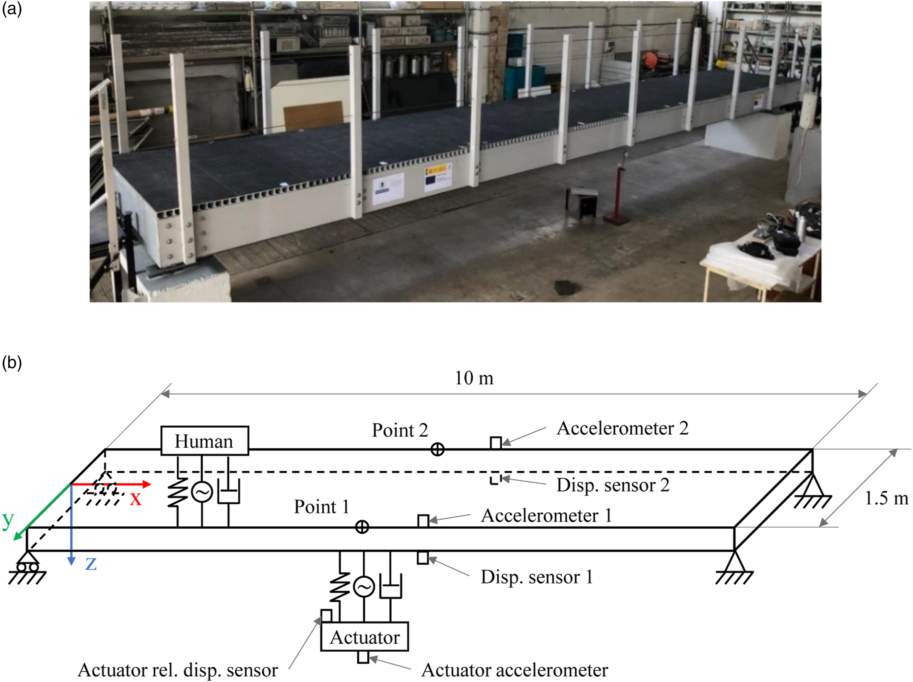
The relationship between the acceleration at a certain point (node) of the structure,
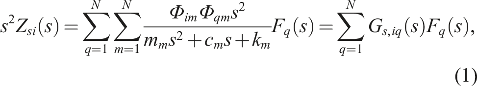
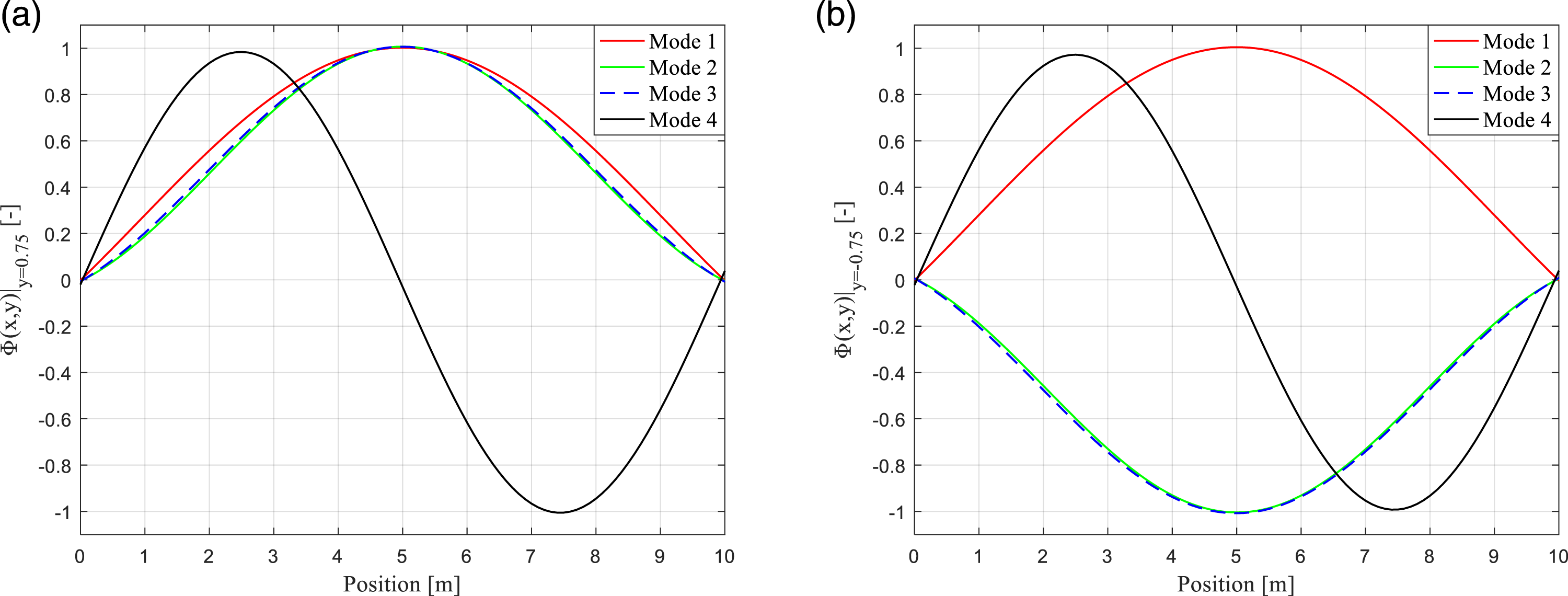
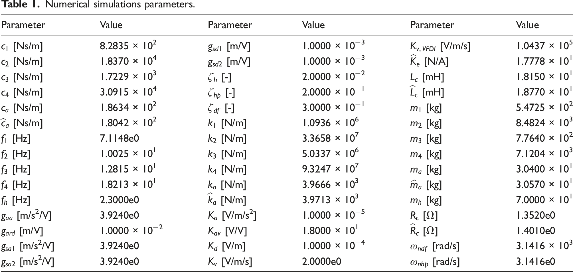
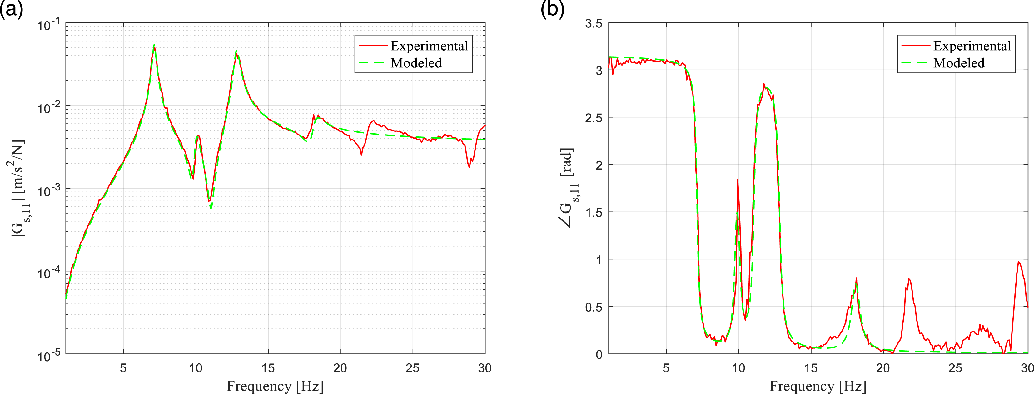
A preliminary Finite Element Analysis (FEA) was conducted to estimate the footbridge modal shapes (Figure 2). A simply supported configuration was considered; therefore, the vertical and lateral translations of the left corners and the vertical, lateral and longitudinal translations of the right corners were constrained (Figure 1(b)). The first four modes take place at 7.329 Hz: first vertical bending mode, 10.425 Hz: first lateral-torsion mode (mainly lateral), 15.507 Hz: second lateral-torsion mode (mainly torsional) and 25.916 Hz: second vertical bending mode. Figure 3 shows the vertical components of the unity-normalized modal shapes at the edges. The TF at point 1, FEA Modal shapes at 7.329 Hz, 10.425 Hz, 15.507 Hz, and 25.916 Hz. Vertical components of modal shapes at footbridge edges. (a) Point 1. (b) Point 2. Numerical simulations parameters. Experimental and modeled structure TF. (a) Magnitude. (b) Phase.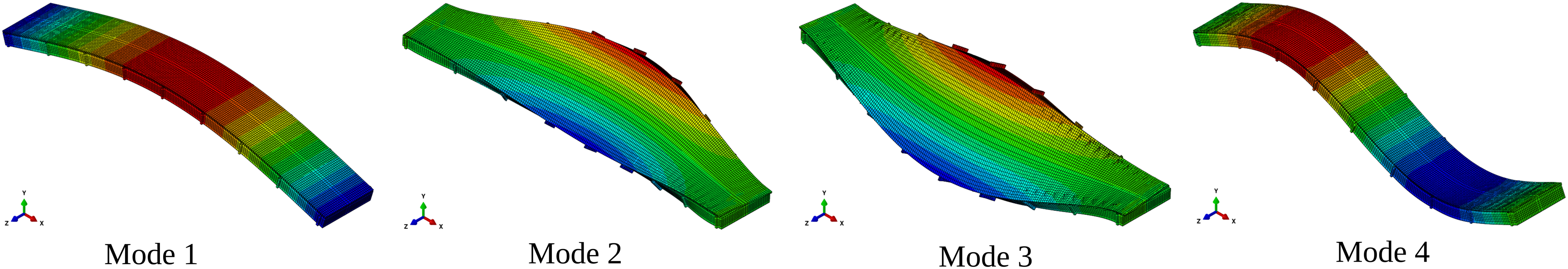
2.2. Human actions and human-structure interaction
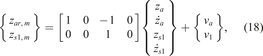
A Mass-Spring-Damper-Actuator (MSDA) system attached to the structure has been used to model the human actions and the HSI phenomenon (Ahmadi et al., 2019, 2021; Díaz et al., 2021; Barrera-Vargas et al., 2022). A human is defined by its equivalent mass, Human actions on the structure. (a) MSDA system. (b) Free-body diagram.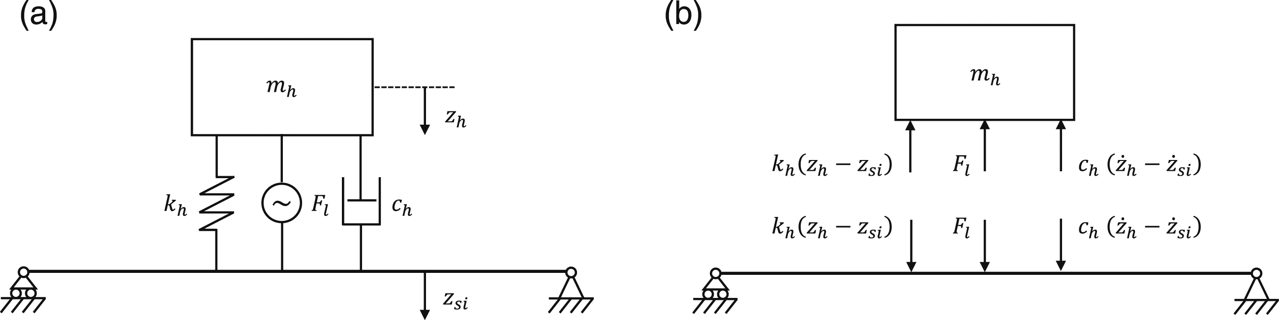
The total force transmitted by the human to the structure, 

Comparing equations (2) and (3), it can be concluded that:
From the LTs of equations (3) and (4) the following relationship is obtained: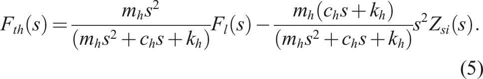
The TF on the first term of the right-hand side of equation (5) relates the force developed by the human’s legs to the part of the force transmitted to the structure, due to the human’s action itself ( Instrumented treadmill walking signal. (a) Time domain. (b) Frequency domain.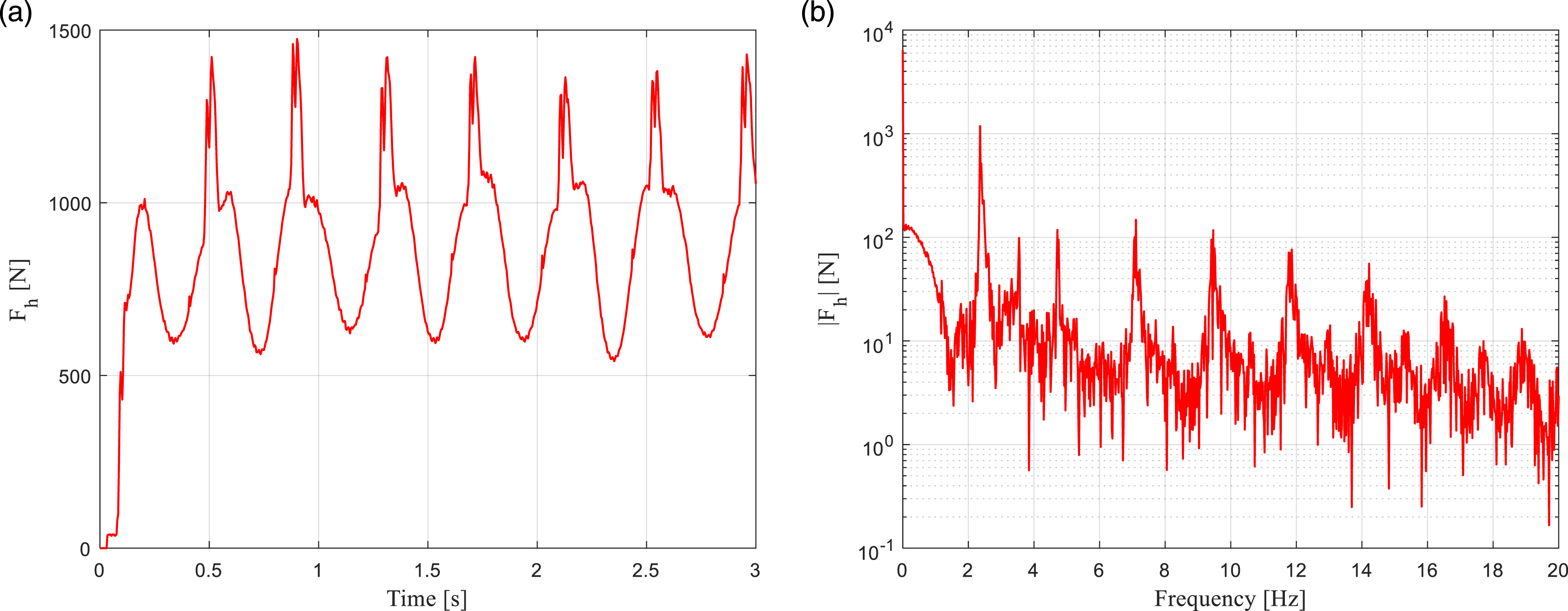
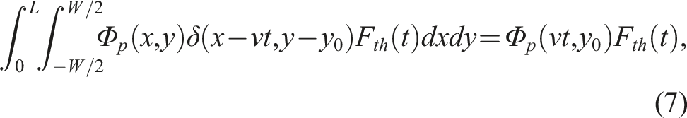
In order to calculate the acceleration at point 1 due to the walking load, it will be assumed that the human’s trajectory coincides with the edge where the PMA is installed (Figure 1(b)). The 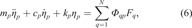
2.3. Proof-mass actuator
The PMA considered to implement the AVA system (Figure 7) is an APS 400 electrodynamic (Lorentz-force based) shaker featuring a frequency range from DC to 200 Hz and a rated force, velocity and stroke of 445 N, 1 m/s and 158 mm, respectively (APS Dynamics, Inc., 2022a). The shaker is driven by an APS 125 amplifier with a rated power of 500 VA (APS Dynamics Inc., 2022b). It is worth noting that this COTS PMA system has been chosen due to its availability, prior successful utilization in simpler AVA systems and flexibility for rapid prototyping purposes. Nevertheless, the PMA parameters do not exactly match the ones ideally required for the application: frequency range is higher than required, while force and displacement might be lower. For permanent implementation, a more cost-effective and application-adapted PMA should be considered. PMA on the footbridge.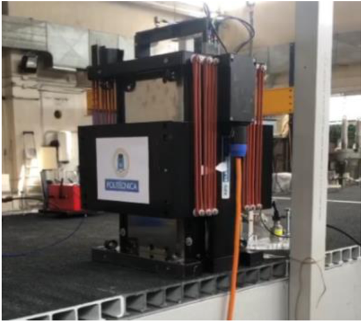
According to Preumont and Seto (2008), the PMA can be modeled as an MSDA system. Figure 8(a) shows the scheme of the PMA acting on the structure. Proceeding similarly as in subsection 2.2, it can be concluded that the force transmitted to the structure by the PMA, PMA scheme. (a) Mechanical part. (b) Electrical part.

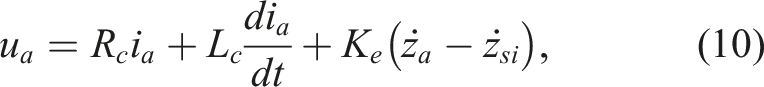

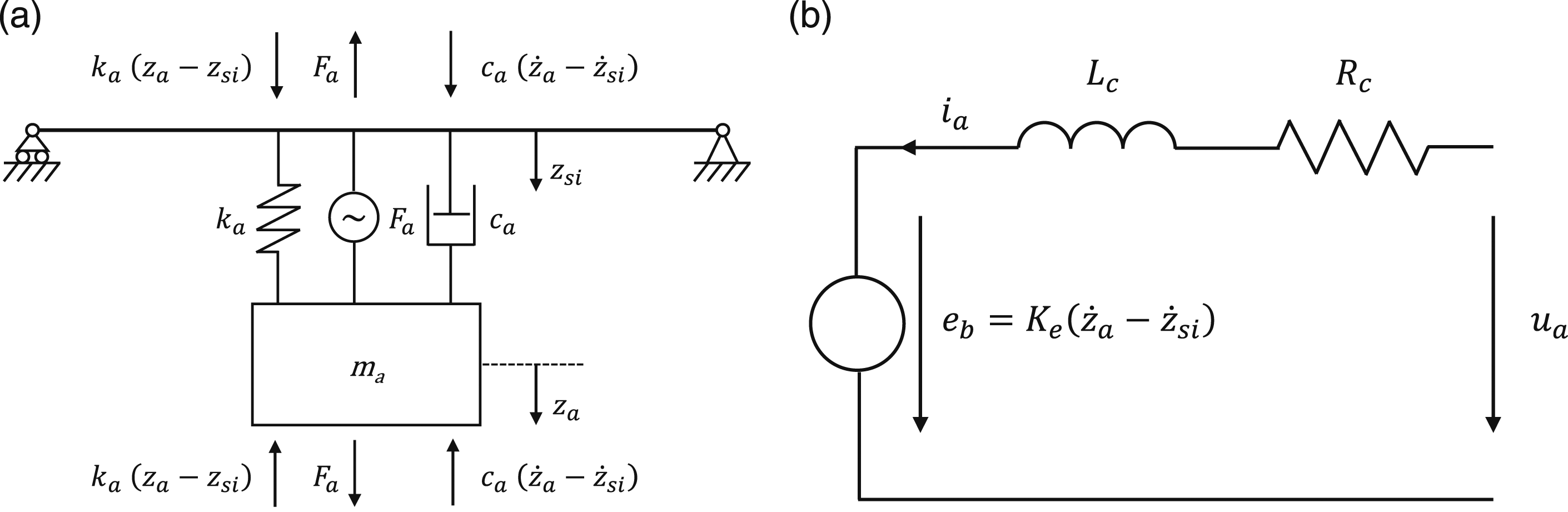
The parameters of the PMA have been identified experimentally. For that purpose, the following expression has been derived from the LTs of equations (8) to (11):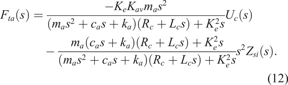
The TF of the first term on the right-hand side of equation (12) relates the control voltage to the part of the force transmitted to the structure due to PMA action itself (
The shaker has been installed on a rigid floor to estimate its TF experimentally. The amplifier has been fed with a constant amplitude swept-sine voltage from 0.1 to 100 Hz and the acceleration of the PMA mass has been measured. With this test set-up, the experimental data must be fit to the first term of equation (12). Figure 9 shows the experimental and modeled TF. As it can be appreciated, the modeled TF accurately approximates the experimental one up to 20 Hz, progressively diverging from that frequency on, due to non-modeled PMA dynamics. Nonetheless, the attained model is considered enough for this work purposes since the dominant modes of the structure and the external actions frequency range fall within this interval and an overall linear behavior is assumed. Table 1 lists the obtained PMA parameters. Experimental and modeled TF 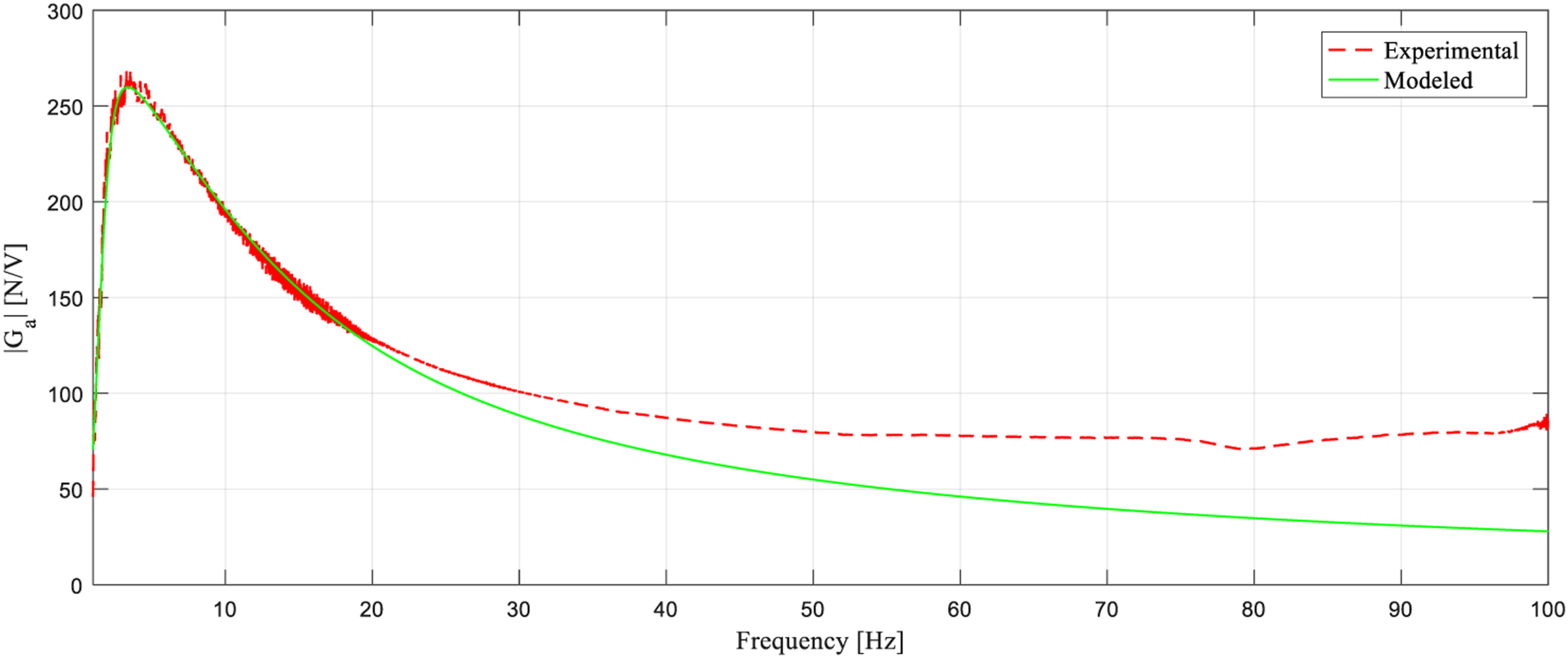
2.4. Electrical noise
Electrical noise has been added to the sensors measurements and to the controller voltage (Figure 10). White noise with a peak value Control system block diagram.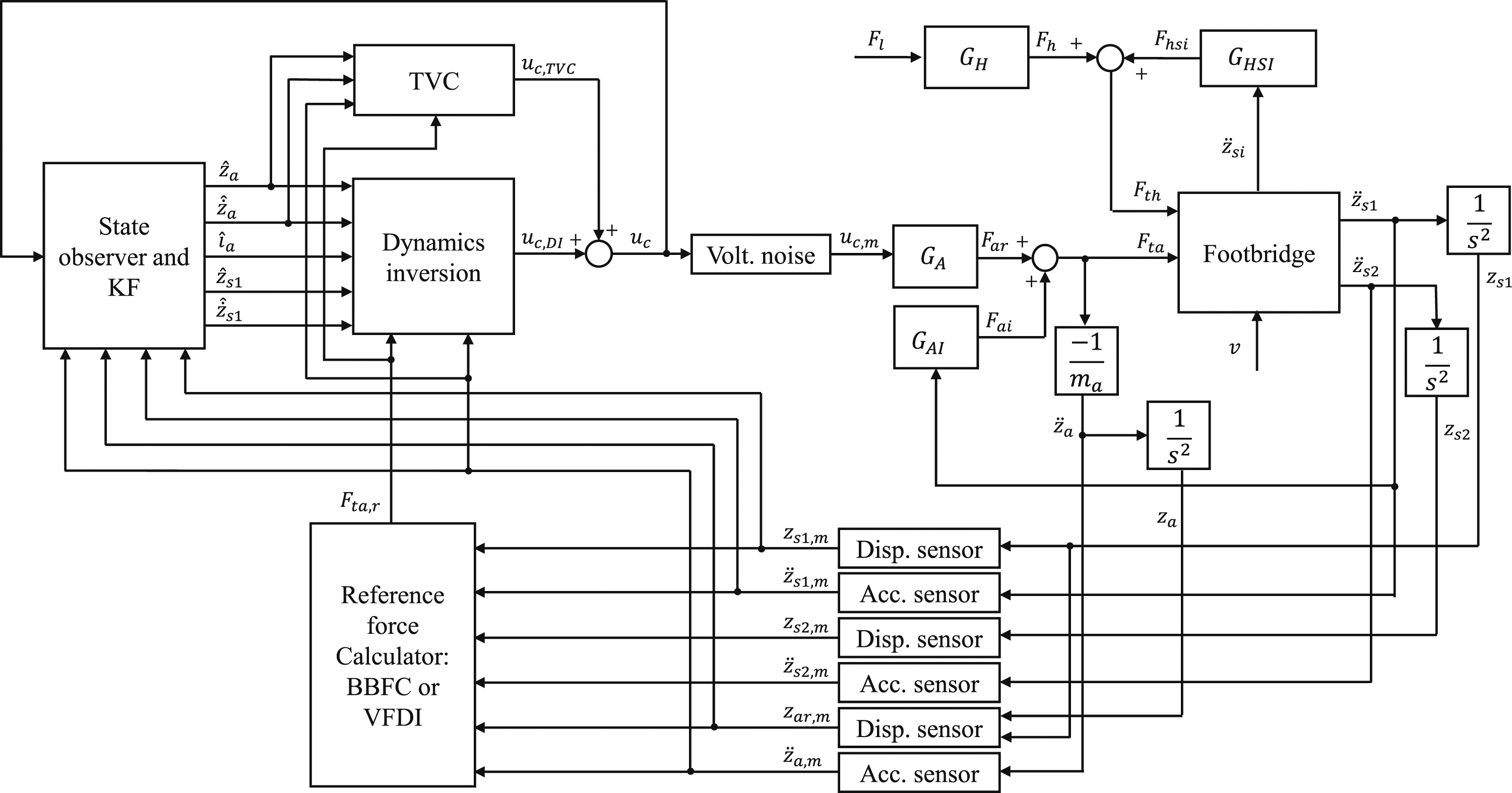
3. Control methodology
The proposed control methodology is explained next. Figure 10 shows the conceptual block diagram corresponding to the proposed control architecture.
3.1. Actuator dynamics inversion
The aim of the DI is to cancel out the internal dynamics of the actuator so that the total force transmitted by the PMA, 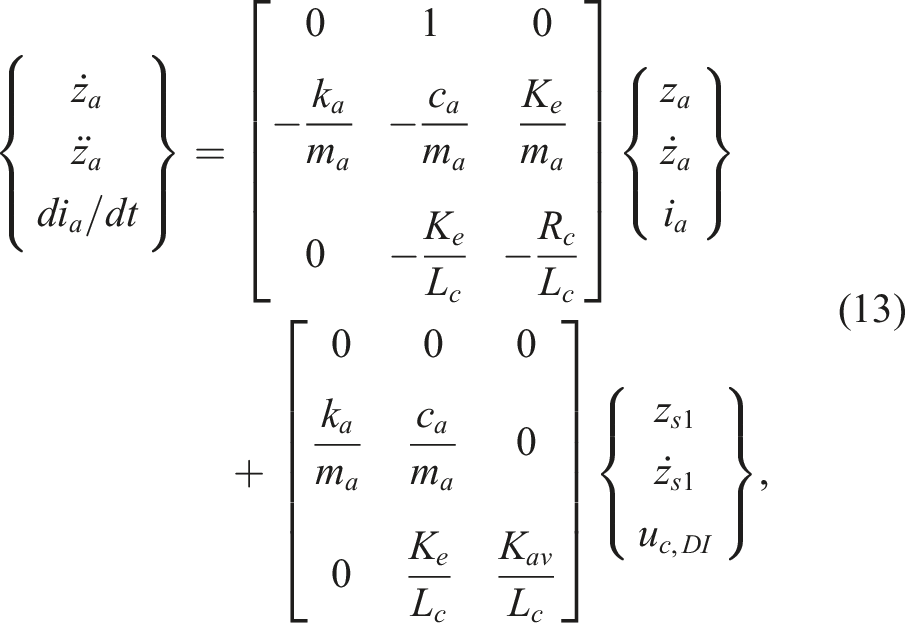
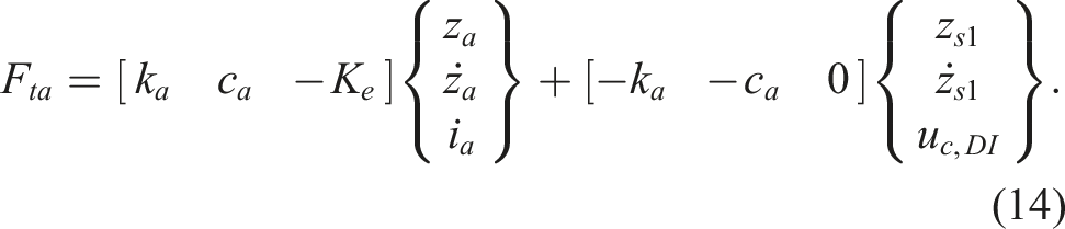
The procedure followed to perform the DI is a particularization of the Structure Algorithm to linear systems in which some of the system inputs are known (Kwatny and Blankenship, 2000; Ramírez-Senent et al., 2021). Therefore, the output equation is differentiated with respect to time successively, until the inputs (
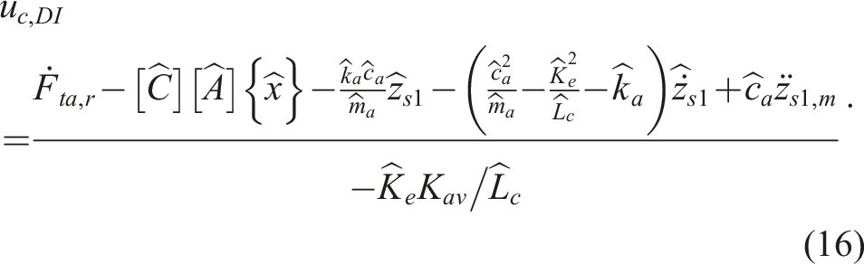
Consequently, the calculation of the control voltage implies estimating the actuator state-space model, the system state vector, the structure displacement, velocity, and acceleration at the PMA location and the target force time derivative.
The actuator state-space model has been identified repeating the procedure outlined in subsection 2.3. The obtained PMA parameters are shown in Table 1 denoted with a hat. The state vector has been estimated by implementing an observer which makes use of the matrices 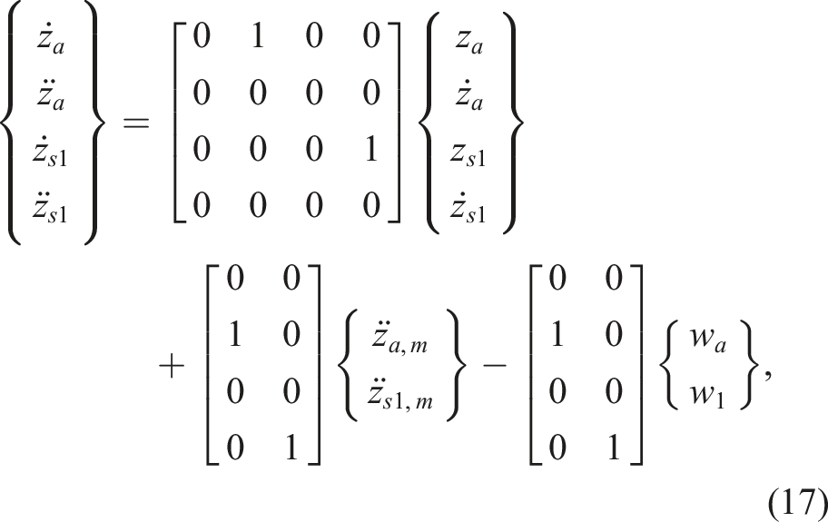
Finally, to calculate the reference force time derivative, 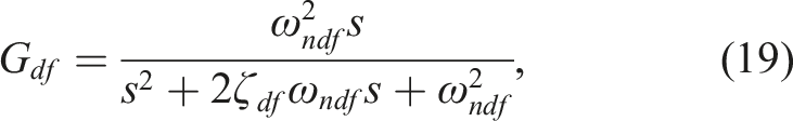
3.2. Parallel Three Variable Controller
A TVC feedback controller has been implemented, in parallel with the DI algorithms, to cope with the modeling errors and improve system stability and robustness. TVC has been adopted to provide simultaneous corrections to PMA mass displacement, velocity, and acceleration errors. The voltage output by the TVC is: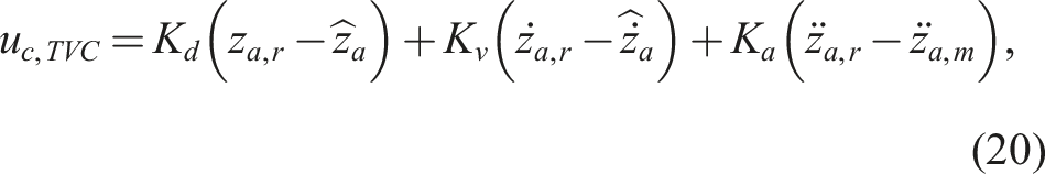
3.3. Control algorithms
3.3.1. The BBFC algorithm
The BBFC algorithm estimates, in real-time, the equivalent external force acting on the structure (excluding the PMA force) and, thanks to the actuator DI procedure, approximately cancels its action forcing the PMA to exert the same force in absolute value, with the opposed sign. The equivalent force on the structure is defined as the force acting on point 1 which causes the same motion as the actual one. Its value: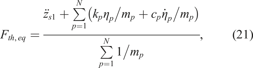
The procedure to estimate the equivalent force is explained next. The force vector acting on the structure can be approximated by: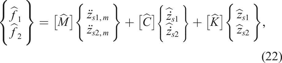
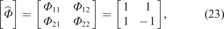

The accelerations in equations (22) and (24) are measured via accelerometers (Figure 1). Structure velocities and displacements are estimated employing a KF, similarly as explained in subsection 3.1, but expanded to account for point 2 displacement and velocity (
Finally, a high-pass filter, 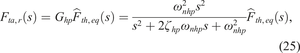
3.3.2. The VFDI algorithm
In order to implement the VFDI, the time derivative of the total force transmitted by the actuator, required by equation (16), must be calculated:
4. Numerical simulations
The results obtained in the simulations carried over the target structure are presented in this section. Table 1 shows the employed parameters. A fourth order Runge-Kutta scheme with a time step of 1 × 10⁻⁴ s has been used in all cases.
4.1. Swept-sine excitation
A swept-sine force has been chosen to illustrate the suggested VCAs theoretical features. Excitation frequency varies linearly from 1 to 20 Hz in 30 s. The amplitude has been linearly modulated during the first 5 seconds until a peak value of 200 N is reached to avoid excessive PMA displacements. Figure 11(a) shows the force envelopes obtained for the BBFC case: the equivalent force on the structure ( BBFC algorithm forces. (a) Force envelopes. (b) Force waveforms.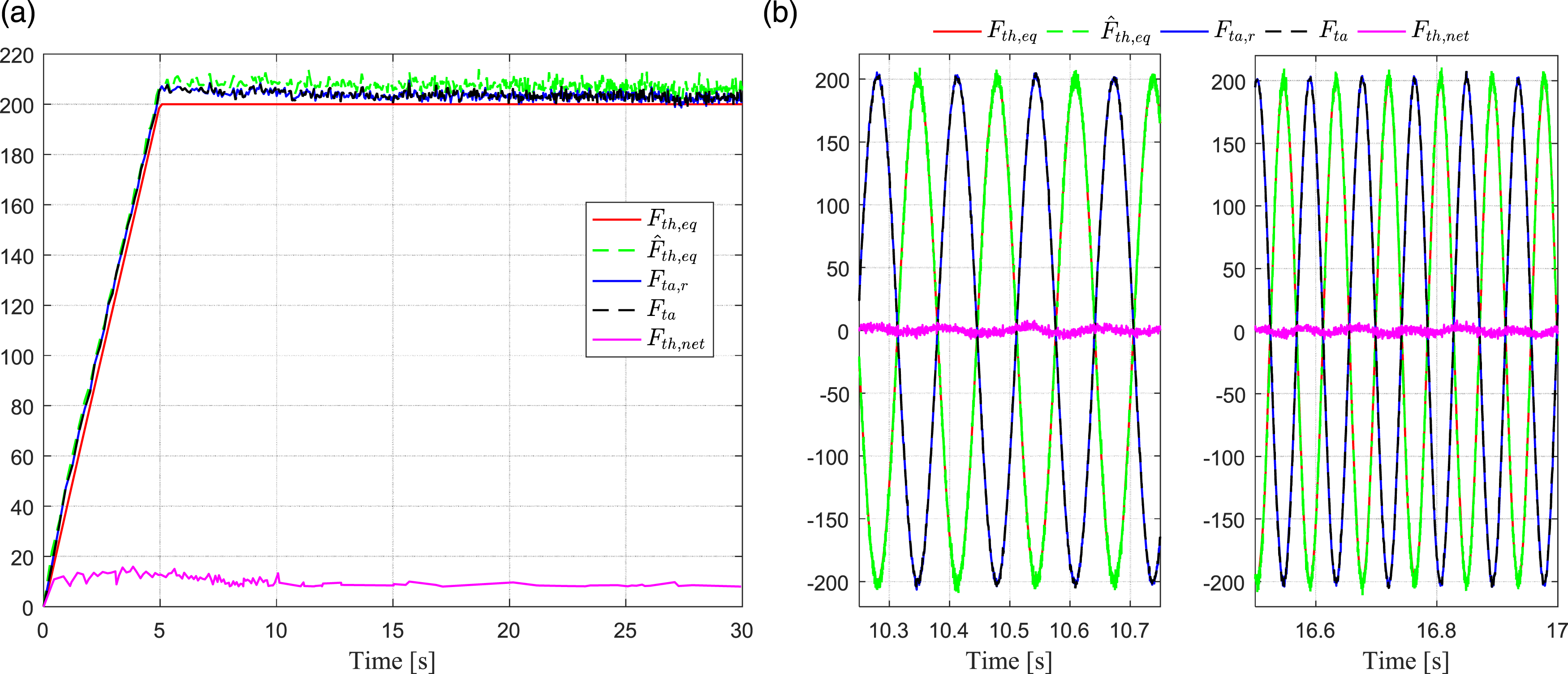
Figure 12 is the counterpart of Figure 11 for the VFDI case. The VFDI algorithm forces. (a) Force envelopes. (b) Force waveforms.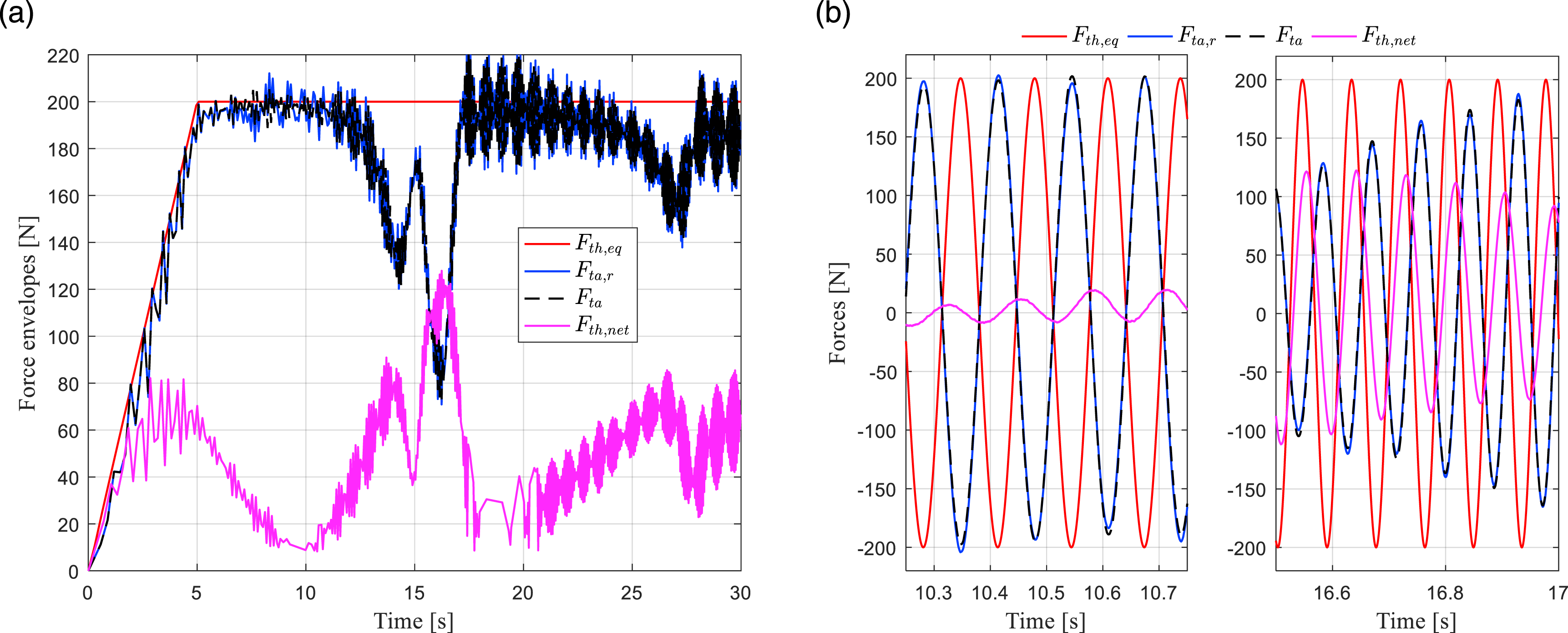
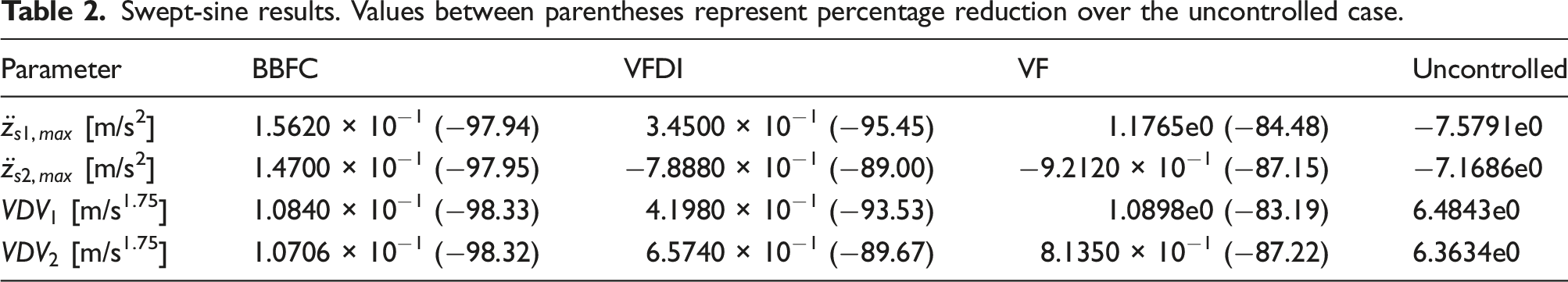
Finally, Figures 13(a) and 13(b) compare the performance of BBFC, VFDI, and a direct VF scheme using the same actuator. The control gain selected value (2.7055 × 10² vs/m) ensures stability. Figure 13(a) shows the acceleration envelopes achieved at points 1 and 2 with the three VCAs and the running vibration dose value (VDV), known as the root-mean-quad method, which quantifies human exposure to vibration. Figure 13(b) displays the closed loop TFs between the external force and the acceleration structure: Comparison between AVA algorithms. (a) Accelerations envelopes and VDVs. (b) Swept-sine results. Values between parentheses represent percentage reduction over the uncontrolled case.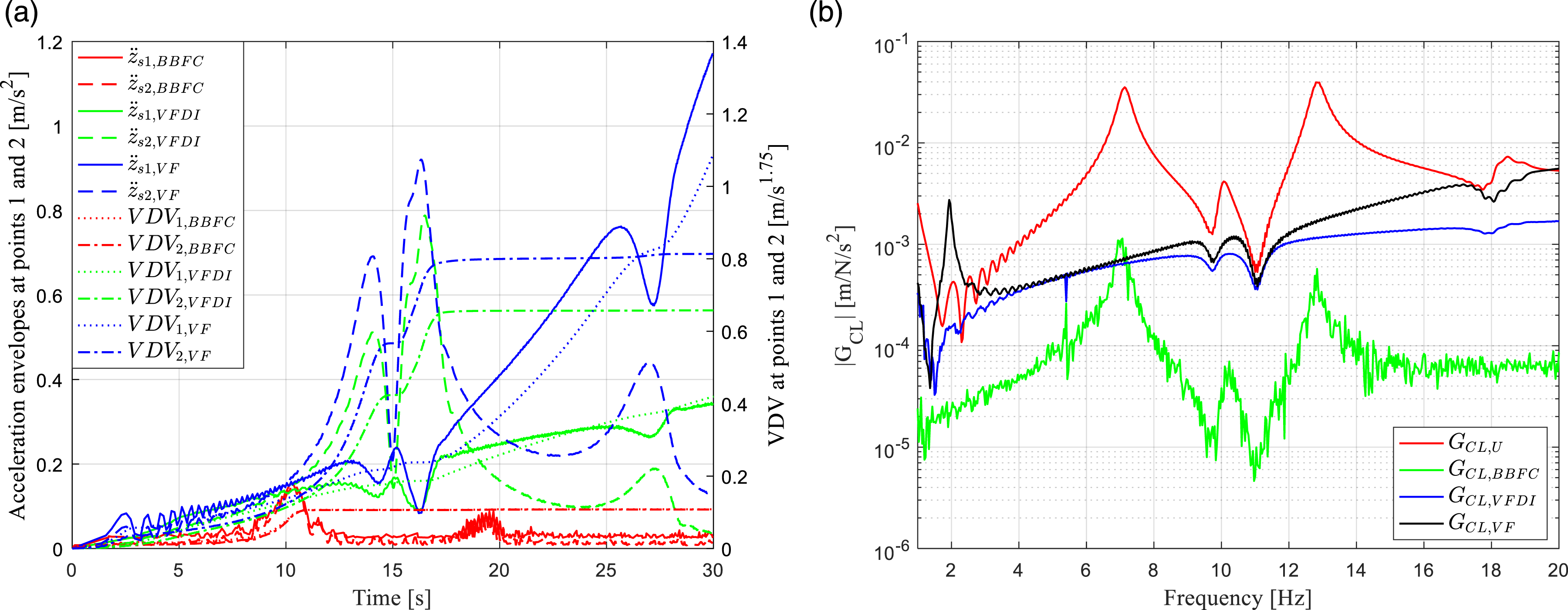
4.2. Walking excitation
The actions of a pedestrian walking at 1.6 m/s along the footbridge edge where the PMA is installed have been simulated to predict the characteristics of the proposed VCAs in a real-life load case. Figure 14(a) displays the forces developed in the BBFC case. The high-pass filter described in subsection 3.3.1 has been replaced, for this case, by two identical filters in series with a cut-off frequency of 0.75 Hz to keep PMA displacements low enough. The obtained equivalent force estimate, Walking test results. BBFC algorithm. (a) Forces. (b) Accelerations and VDVs.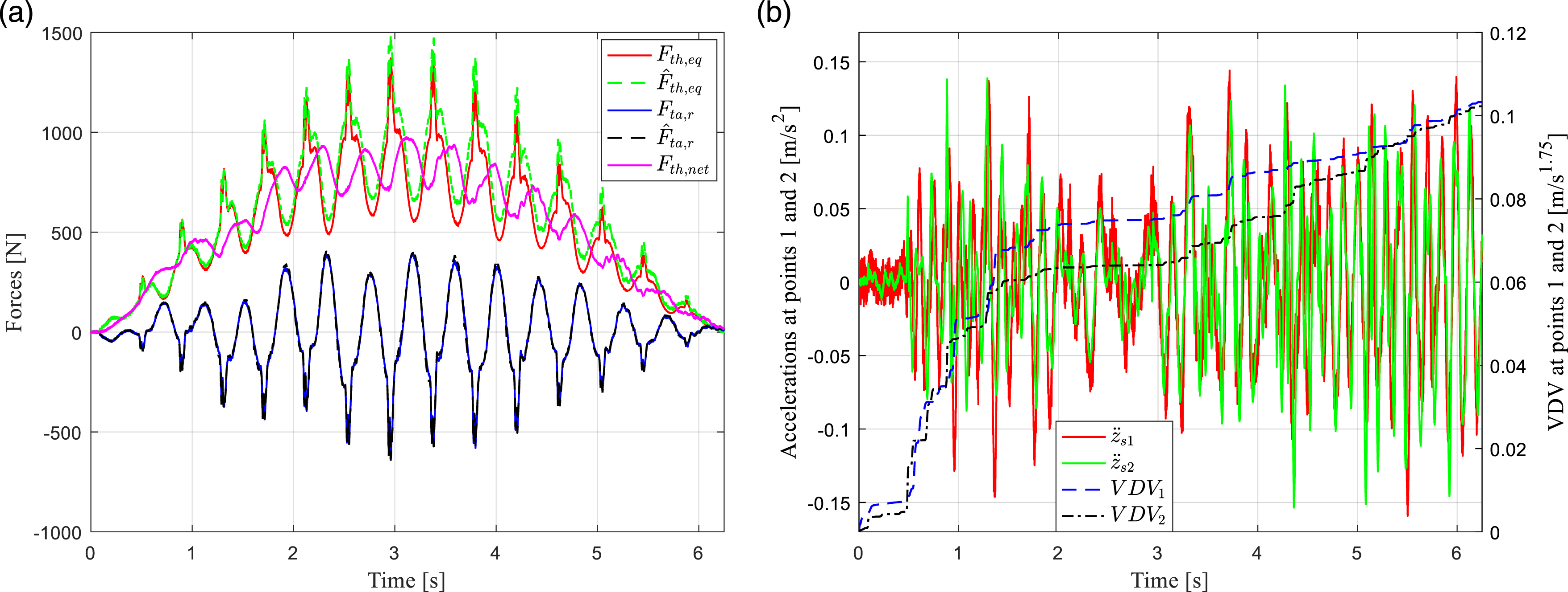
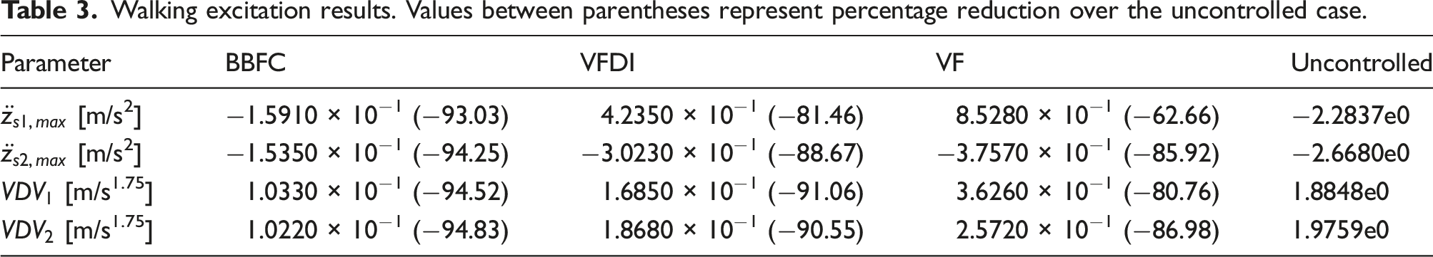
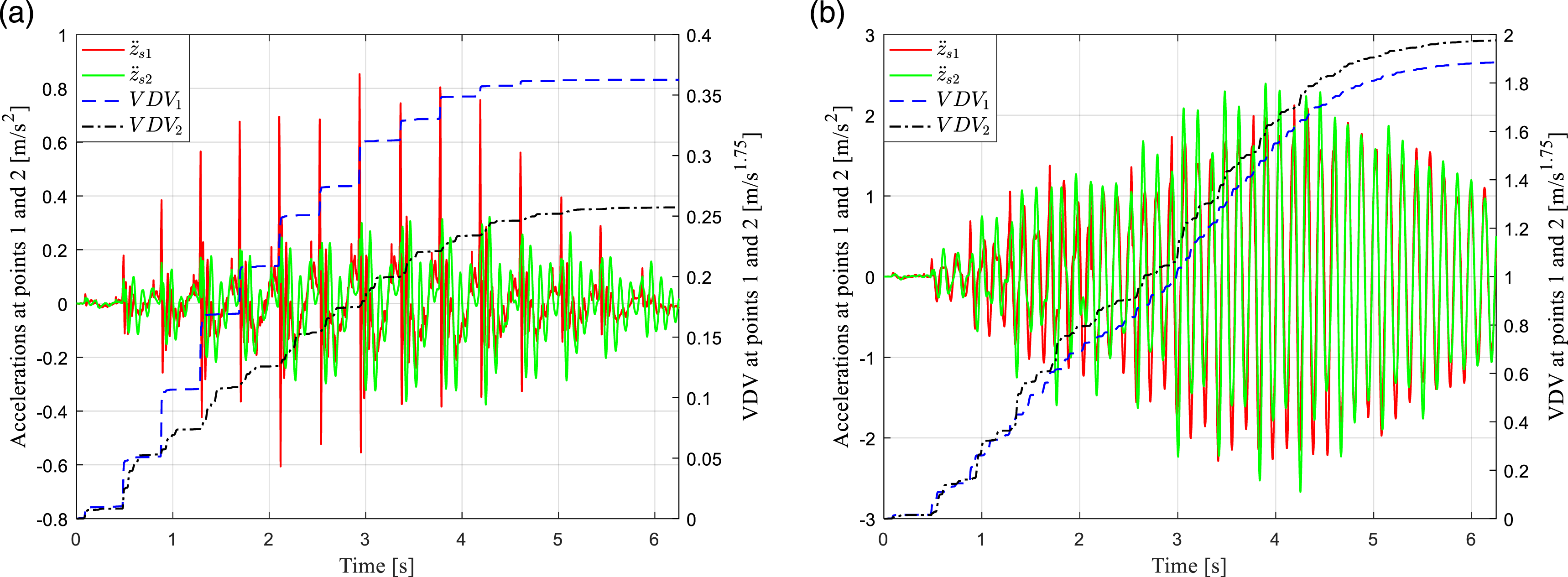
Figure 15 is the counterpart of Figure 14 for the VFDI case. Again, the force tracking is very precise attaining a maximum error of −0.91 N (−0.20%). The reduction in the acceleration response with respect to the uncontrolled case is noticeable (Table 3), but lower than in the BBFC case, both in peak and VDV terms: 81.46% and 91.06%, respectively, at point 1. This is so, because the overall advantages of the BBFC method over the VFDI at frequencies other than the first resonance outweigh those of the VFDI for the actual, multi-component, analyzed load. Lastly, Figures 16(a) and 16(b) show the acceleration response and VDVs at points 1 and 2 for the VF and uncontrolled cases. Despite the fact that the VF approach leads to a considerable vibration attenuation (62.66% in peak acceleration and 80.76% for VDV at point 1), its performance is far from that of the algorithms incorporating DI. Table 3 summarizes the results of the walking load tests. Walking test results. VFDI algorithm. (a) Forces. (b) Accelerations and VDVs. Walking excitation results. Values between parentheses represent percentage reduction over the uncontrolled case. Walking test accelerations and VDVs. (a) VF. (b) Uncontrolled case.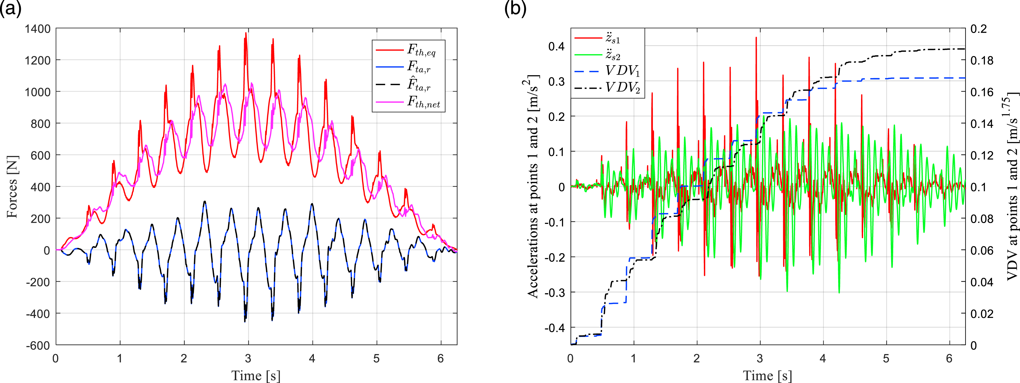
5. Conclusions
In this article, DI techniques have been applied to electrodynamic-actuator–based AVA systems for human-induced vibrations. The DI algorithm has been derived from an identified state-space model of the PMA system. DI implementation implies estimating the displacement, velocity and acceleration at the PMA installation point; therefore, the acceleration and the absolute displacement of that point must be measured. The proposed architecture is completed with a parallel TVC which improves overall stability and robustness. The DI has been applied to the direct VF technique deriving the VFDI algorithm and to a novel approach: the BBFC algorithm. The BBFC consists in estimating, in real-time, the equivalent external force acting on the structure and imposing it back, negated, so that external actions are approximately canceled. The force estimation requires measuring the displacement and acceleration at another point of the structure and relies on a structural model which can be experimentally identified with the suggested configuration. The effectiveness of the proposed techniques has been assessed via numerical simulations carried over a realistic model. Two loading scenarios have been analyzed: a fixed swept-sine force at the midspan of the footbridge and a walking load considering the HSI phenomenon. Simulation outcomes indicate that DI leads to an excellent tracking of the force reference calculated by the suggested VCAs achieving maximum control errors of 1.20 N (0.57%) and −8.07 N (−3.62%), respectively, for the BBFC and the VFDI in the swept-sine test and of −37.73 N (−6.05%) and −0.91 N (−0.20%) in the walking load case. In addition, the equivalent force estimate carried out in the BBFC algorithm is quite reasonable, reaching maximum discrepancies of 16.41 N (8.20%) and −156.44 N (11.41%), respectively, for the swept-sine and walking tests. Results for the swept-sine load show that the BBFC algorithm clearly outperforms the VFDI in the whole frequency range, excepting for a narrow band near the first resonant frequency, mainly due to structural modeling errors. Nevertheless, the overall attenuation with respect to the uncontrolled case is better in the BBFC case, both in terms of peak accelerations (97.94% vs 95.45% at the control point) and VDV values (97.95% vs 93.53% at the control point). Consequently, it can be concluded that the BBFC algorithm minimizes the vibration levels in the structure within the whole excitation frequency range, whereas the VFDI approach performs well at resonances affecting the control point. The results obtained for the walking excitation are better for the BBFC than for the VFDI case for all the evaluated parameters, achieving reductions with respect to the uncontrolled case, at the control point, of 93.03% against 81.46% in peak accelerations and of 94.52% against 91.06% in VDVs. In both scenarios, the new algorithms incorporating DI yield an excellent attenuation in comparison with the classical VF approach, which attains reductions in comparison with the uncontrolled case, at the control point, of 84.48% and 62.66% in the peak accelerations for the swept-sine and walking cases, respectively, and of 83.19% and 80.76% in the VDVs. Future works include the evaluation of the stability and robustness of the proposed schemes, the addition of constraints to avoid PMA saturations and the actual implementation in the footbridge analyzed herein.
Footnotes
Acknowledgments
Christian Gallegos-Calderón thanks the Secretariat of Higher Education, Science, Technology and Innovation of Ecuador for the PhD scholarship CZ02-000167-2018.
Declaration of conflicting interests
The author(s) declared no potential conflicts of interest with respect to the research, authorship, and/or publication of this article.
Funding
The author(s) disclosed receipt of the following financial support for the research, authorship, and/or publication of this article: This work was supported by Grant RTI2018-099639-B-I00 funded by MCIN/AEI/ 10.13039/501100011033 and by “ERDF A way of making Europe”.